EP2381078A1 - Exhaust gas purifying system, method for manufacturing an exhaust gas purifying system and exhaust gas purifying method using an exhaust gas purifying system - Google Patents
Exhaust gas purifying system, method for manufacturing an exhaust gas purifying system and exhaust gas purifying method using an exhaust gas purifying system Download PDFInfo
- Publication number
- EP2381078A1 EP2381078A1 EP11159541A EP11159541A EP2381078A1 EP 2381078 A1 EP2381078 A1 EP 2381078A1 EP 11159541 A EP11159541 A EP 11159541A EP 11159541 A EP11159541 A EP 11159541A EP 2381078 A1 EP2381078 A1 EP 2381078A1
- Authority
- EP
- European Patent Office
- Prior art keywords
- exhaust gas
- gas purifying
- sealing material
- holding sealing
- purifying apparatus
- Prior art date
- Legal status (The legal status is an assumption and is not a legal conclusion. Google has not performed a legal analysis and makes no representation as to the accuracy of the status listed.)
- Granted
Links
Images







Classifications
-
- F—MECHANICAL ENGINEERING; LIGHTING; HEATING; WEAPONS; BLASTING
- F01—MACHINES OR ENGINES IN GENERAL; ENGINE PLANTS IN GENERAL; STEAM ENGINES
- F01N—GAS-FLOW SILENCERS OR EXHAUST APPARATUS FOR MACHINES OR ENGINES IN GENERAL; GAS-FLOW SILENCERS OR EXHAUST APPARATUS FOR INTERNAL-COMBUSTION ENGINES
- F01N3/00—Exhaust or silencing apparatus having means for purifying, rendering innocuous, or otherwise treating exhaust
- F01N3/08—Exhaust or silencing apparatus having means for purifying, rendering innocuous, or otherwise treating exhaust for rendering innocuous
- F01N3/10—Exhaust or silencing apparatus having means for purifying, rendering innocuous, or otherwise treating exhaust for rendering innocuous by thermal or catalytic conversion of noxious components of exhaust
- F01N3/24—Exhaust or silencing apparatus having means for purifying, rendering innocuous, or otherwise treating exhaust for rendering innocuous by thermal or catalytic conversion of noxious components of exhaust characterised by constructional aspects of converting apparatus
- F01N3/28—Construction of catalytic reactors
- F01N3/2839—Arrangements for mounting catalyst support in housing, e.g. with means for compensating thermal expansion or vibration
- F01N3/2853—Arrangements for mounting catalyst support in housing, e.g. with means for compensating thermal expansion or vibration using mats or gaskets between catalyst body and housing
- F01N3/2857—Arrangements for mounting catalyst support in housing, e.g. with means for compensating thermal expansion or vibration using mats or gaskets between catalyst body and housing the mats or gaskets being at least partially made of intumescent material, e.g. unexpanded vermiculite
-
- F—MECHANICAL ENGINEERING; LIGHTING; HEATING; WEAPONS; BLASTING
- F01—MACHINES OR ENGINES IN GENERAL; ENGINE PLANTS IN GENERAL; STEAM ENGINES
- F01N—GAS-FLOW SILENCERS OR EXHAUST APPARATUS FOR MACHINES OR ENGINES IN GENERAL; GAS-FLOW SILENCERS OR EXHAUST APPARATUS FOR INTERNAL-COMBUSTION ENGINES
- F01N3/00—Exhaust or silencing apparatus having means for purifying, rendering innocuous, or otherwise treating exhaust
- F01N3/08—Exhaust or silencing apparatus having means for purifying, rendering innocuous, or otherwise treating exhaust for rendering innocuous
- F01N3/10—Exhaust or silencing apparatus having means for purifying, rendering innocuous, or otherwise treating exhaust for rendering innocuous by thermal or catalytic conversion of noxious components of exhaust
- F01N3/24—Exhaust or silencing apparatus having means for purifying, rendering innocuous, or otherwise treating exhaust for rendering innocuous by thermal or catalytic conversion of noxious components of exhaust characterised by constructional aspects of converting apparatus
- F01N3/28—Construction of catalytic reactors
- F01N3/2839—Arrangements for mounting catalyst support in housing, e.g. with means for compensating thermal expansion or vibration
- F01N3/2853—Arrangements for mounting catalyst support in housing, e.g. with means for compensating thermal expansion or vibration using mats or gaskets between catalyst body and housing
-
- F—MECHANICAL ENGINEERING; LIGHTING; HEATING; WEAPONS; BLASTING
- F01—MACHINES OR ENGINES IN GENERAL; ENGINE PLANTS IN GENERAL; STEAM ENGINES
- F01N—GAS-FLOW SILENCERS OR EXHAUST APPARATUS FOR MACHINES OR ENGINES IN GENERAL; GAS-FLOW SILENCERS OR EXHAUST APPARATUS FOR INTERNAL-COMBUSTION ENGINES
- F01N2450/00—Methods or apparatus for fitting, inserting or repairing different elements
- F01N2450/02—Fitting monolithic blocks into the housing
-
- Y—GENERAL TAGGING OF NEW TECHNOLOGICAL DEVELOPMENTS; GENERAL TAGGING OF CROSS-SECTIONAL TECHNOLOGIES SPANNING OVER SEVERAL SECTIONS OF THE IPC; TECHNICAL SUBJECTS COVERED BY FORMER USPC CROSS-REFERENCE ART COLLECTIONS [XRACs] AND DIGESTS
- Y10—TECHNICAL SUBJECTS COVERED BY FORMER USPC
- Y10T—TECHNICAL SUBJECTS COVERED BY FORMER US CLASSIFICATION
- Y10T29/00—Metal working
- Y10T29/49—Method of mechanical manufacture
- Y10T29/49428—Gas and water specific plumbing component making
Definitions
- the present invention relates to an exhaust gas purifying system, a method for manufacturing an exhaust gas purifying system, and an exhaust gas purifying method using an exhaust gas purifying system.
- PMs particulate matters
- exhaust gases also contain toxic gas components, such as CO (carbon monoxide), HC (hydrocarbon) or NOx (nitrogen oxides), and these toxic gas components have also raised serious problems as contaminants harmful to the environment and the human body.
- exhaust gas purifying apparatuses that is coupled to an internal combustion engine so that PMs in exhaust gases are captured therein and toxic gas components contained in exhaust gases, such as CO, HC, NOx or the like, are purified
- various exhaust gas purifying apparatuses each of which is composed of an exhaust gas treating body made from a porous ceramic material such as cordierite, silicon carbide, or the like, a metal casing used for housing the exhaust gas treating body therein, and a mat-shaped holding sealing material containing inorganic fibers, which is placed between the exhaust gas treating body and the metal casing.
- the holding sealing material is allowed to hold the exhaust gas treating body by the elasticity possessed by the inorganic fibers.
- exhaust gases are prevented from leaking through a gap between the exhaust gas treating body and the metal casing.
- an exhaust gas treating body around which a holding sealing material is wound is stuffed (press-fitted) to the inside of a metal casing.
- a metal casing which has an inner diameter that is slightly shorter than the outer diameter (the combined length of the diameter of the exhaust gas treating body and the thickness of the holding sealing material) of the exhaust gas treating body around which the holding sealing material is wound, may be used.
- the exhaust gas treating body around which the holding sealing material has been wound is referred to also as "wound body".
- the holding sealing material is brought into a compressed state inside the metal casing. Consequently, the holding sealing material is allowed to exert a restoring force (that is, holding strength for holding the exhaust gas treating body) for trying to return to its original shape by the elasticity possessed by inorganic fibers so that the exhaust gas treating body is held by the holding sealing material.
- a restoring force that is, holding strength for holding the exhaust gas treating body
- an inlet pipe for introducing exhaust gases into the exhaust gas purifying apparatus is connected to one of the ends of the exhaust gas purifying apparatus, and an exhaust pipe for externally discharging the exhaust gases that have passed through the exhaust gas purifying apparatus is connected to the other end of the exhaust gas purifying apparatus so that an exhaust gas purifying system can be manufactured.
- the side of the end portion to which the inlet pipe is connected is referred to as "gas inlet side”
- the side of the end portion to which the exhaust pipe is connected is referred to as "gas outlet side”.
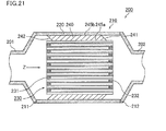
- Fig. 21 is a cross-sectional view that schematically illustrates one example of a conventional exhaust gas purifying system.
- the stuffing direction is indicated by an arrow "Z". In this manner, in the conventional exhaust gas purifying system, the stuffing direction and the flowing direction of exhaust gases are the same direction.
- the first side face 241 of a holding sealing material 240 is not made substantially in parallel with an outlet side end face 232 of an exhaust gas treating body 230 to cause a tilted state.
- the second side face 242 of the holding sealing material 240 is not made substantially in parallel with an inlet side end face 231 of the exhaust gas treating body 230 to cause a tilted state.
- the shearing force is exerted in a stuffing direction on the first main face 245a side of the holding sealing material 240, and is also exerted in a direction opposite to the stuffing direction on the second main face 245b side of the holding sealing material 240. It is considered that, as a result, the positions of the first main face 245a and the second main face 245b of the holding sealing material 240 are mutually displaced, with the result that the holding sealing material 240 is deformed.
- the expression "substantially in parallel with” indicates a state in which the end face (inlet side end face or outlet side end face) of the exhaust gas treating body is kept in parallel with the first side face or the second side face of the holding sealing material or a state in which, even when the first side face or the second side face of the holding sealing material is tilted relative to the end face of the exhaust gas treating body, the degree of the tilt can be virtually ignored.
- the wind erosion generated on the first side face 241 or the second side face 242 of the holding sealing material 240 tends to progress to cause damages in the holding sealing material 240.
- a damage caused in the holding sealing material 240 it fails to sufficiently hold the exhaust gas treating body 230, as a result, a problem arises in that exhaust gases are leaked from a gap caused by the wind erosion, or in some cases, a problem arises in that the exhaust gas treating body 230 comes off.
- Patent Document 1 an exhaust gas purifying apparatus that uses a holding sealing material having a side face on which a slanting face is formed has been proposed, and a method for manufacturing such an exhaust gas purifying apparatus has also been proposed.
- Patent Document 1 JP-A 2007-092553
- a holding sealing material to be used in the exhaust gas purifying apparatus described in Patent Document 1 first, the side face of the holding sealing material is cut by using a cutting tool, such as a cutter, to form a slanting face that is tilted from a first main face side to a second main face side.
- a cutting tool such as a cutter
- the holding sealing material is wound around the peripheral portion of the exhaust gas treating body as a single layer so that a wound body is manufactured, with this side face (slanting face) of the holding sealing material protruding in a stuffing direction at the time when the wound body is stuffed to the metal casing.
- the wound body thus manufactured is stuffed to the metal casing, it is considered that as the second main face and the proximity thereof are deformed in a direction opposite to the stuffing direction, the slanting face is gradually made in parallel with the end face of the exhaust gas treating body. Moreover, in a state where the wound body is disposed at a predetermined position, the second side face of the holding sealing material is supposed to be made just substantially in parallel with the end face of the exhaust gas treating body.
- FIG. 22(a) is a cross-sectional view that schematically illustrates another example of a conventional exhaust gas purifying system prior to allowing exhaust gases to flow therein
- Fig. 22(b) is a cross-sectional view that schematically illustrates another example of a conventional exhaust gas purifying system with exhaust gases flowing thereto.
- the gap between the exhaust gas treating body and the metal casing is completely filled with the holding sealing material at a portion where the first side face or the second side face of the holding sealing material is not tilted.
- the holding sealing material can push out the exhaust gas treating body and the metal casing perpendicularly. As a result, a facial pressure (pressure applied to the holding face of the holding sealing material) is generated on the holding sealing material.
- the facial pressure effective area corresponds to an area of a portion indicated by "S 3 ".
- the facial pressure effective area corresponds to an area of a portion indicated by "S 4 ".
- the present invention is devised in order to solve the problems, and an object of the present invention is to provide an exhaust gas purifying system including an exhaust gas purifying apparatus that allows the holding sealing material to sufficiently hold the exhaust gas treating body even during flowing of exhaust gases, as well as a method for manufacturing such an exhaust gas purifying system and an exhaust gas purifying method in which the exhaust gas purifying system is used.
- the present inventors have made intensive investigations to solve the above problems, and as a result, have found that, by taking into consideration that an exhaust gas treating body is moved in response to flowing of exhaust gases, a slanting face is formed on a side face of a holding sealing material so that the holding strength of the holding sealing material is prevented from being lowered; thus, a present invention has been completed.
- an exhaust gas purifying system includes:
- the first side face of the holding sealing material is tilted in a direction reversed to that of an exhaust gas purifying system produced by a conventional method.
- the exhaust gas treating body is pushed toward a gas outlet side of the exhaust gas purifying apparatus in response to the flowing of the exhaust gases.
- a first slanting face formed on the first side face of the holding sealing material is shifted in a flowing direction of the exhaust gases that is, toward the gas outlet side of the exhaust gas purifying apparatus, so that the first side face is gradually made to be substantially in parallel with the end face of the exhaust gas treating body.
- the exhaust gas purifying system according to claim 1 different from an exhaust gas purifying system manufactured by a conventional method, a sufficient facial pressure is generated relative to the exhaust gas treating body and the metal casing. As a result, since the holding strength of the holding sealing material is prevented from being lowered even during flowing of exhaust gases, the holding sealing material can sufficiently hold the exhaust gas treating body.
- the holding sealing material forming the exhaust gas purifying apparatus is allowed to exert sufficient holding strength, it becomes possible to reduce a gap bulk density (GBD) of the holding sealing material to be placed between the exhaust gas treating body and the metal casing. As a result, the amount of the holding sealing material forming the exhaust gas purifying apparatus can be reduced.
- GBD gap bulk density
- the amount of scattered inorganic fibers forming the holding sealing material from the gas inlet side of the exhaust gas purifying apparatus toward an internal combustion engine can be reduced.
- the effect is considered to be derived from the fact that in the exhaust gas purifying system according to claim 1, the inorganic fibers are constrained by the holding strength of the holding sealing material forming the exhaust gas purifying apparatus.
- a second slanting face is formed on the second side face of the holding sealing material, on a cross section in parallel with a longitudinal direction of the exhaust gas purifying apparatus, the second slanting face has a second inside end point at which the holding sealing material and the exhaust gas treating body are made in contact with each other and a second outside end point at which the holding sealing material and the metal casing are made in contact with each other, the second inside end point is positioned closer to the gas inlet side of the exhaust gas purifying apparatus than the second outside end point, and the second slanting face is directed to the second outside end point from the second inside end point, with the second slanting face being tilted relative to an end face of the exhaust gas treating body.
- a slanting face is also formed on the second side face of the holding sealing material.
- the second side face of the holding sealing material is tilted in a direction reversed to that in the exhaust gas purifying system manufactured by a conventional method.
- the exhaust gas purifying system according to claim 2 makes it possible to increase the facial pressure relative to the exhaust gas treating body and the metal casing.
- the holding sealing material forming the exhaust gas purifying apparatus can exert a greater holding strength than that of the holding sealing material in the exhaust gas purifying apparatus forming the exhaust gas purifying system according to claim 1.
- a first angle formed by a line segment connecting the first inside end point to the first outside end point and an inner circumference of the metal casing is 25 to 89.5°.
- the holding sealing material since the deformation of the holding sealing material in the exhaust gas purifying apparatus becomes too large, the holding sealing material tends to be easily damaged.
- the holding sealing material fails to exert a sufficient holding strength.
- the first angle exceeds 89.5°, the effect of the installation of the first slanting face on the holding sealing material in the exhaust gas purifying apparatus is not sufficiently obtained.
- the holding sealing material has a plurality of needle marks formed by a needling treatment.
- the needle marks are formed on the holding sealing material forming the exhaust gas purifying apparatus, upon stuffing the wound body into the metal casing, the needle marks of the holding sealing material exert a predetermined directivity.
- the predetermined directivity is exerted by the holding sealing material in the exhaust gas purifying apparatus, the push-out intensity applied to the exhaust gas treating body and the metal casing by the holding sealing material is increased so that it is considered that the holding strength of the holding sealing material is improved.
- the holding sealing material having the needle marks exerts greater holding strength.
- the holding sealing material includes inorganic fibers
- the inorganic fibers are aligned in a direction perpendicular to the surface of the holding sealing material in the needle marks.
- the push-out intensity applied to the exhaust gas treating body and the metal casing in the direction of the needle marks (aligned direction of the inorganic fibers) by the holding sealing material is considered to increase.
- the plurality of needle marks are formed in a direction diagonal to the thickness direction of the holding sealing material.
- the holding strength of the holding sealing material is considered to be further improved.
- a binder is applied to the holding sealing material.
- the inorganic fibers forming the holding sealing material can be mutually anchored. Therefore, when the binder is applied to the holding sealing material forming the exhaust gas purifying apparatus, the direction of the needle marks can be easily maintained. For this reason, in the exhaust gas purifying apparatus, the push-out intensity applied to the exhaust treating body and the metal casing by the holding sealing material becomes greater. As a result, the holding strength of the holding sealing material in the exhaust gas purifying apparatus is considered to be improved.
- the binder applied to the holding sealing material has an amount of 10% by weight or less.
- the holding strength of the holding sealing material in the exhaust gas purifying apparatus can be improved.
- the amount of the binder to be applied to the holding sealing material is preferably set to 10% by weight or less.
- the effect of improving the holding strength of the holding sealing material is considered to be reduced.
- the binder components are thermally decomposed with the result that a problem arises in that much decomposed gas is generated.
- the metal casing has a distinguished gas inlet side forming the gas inlet side of the exhaust gas purifying apparatus and a distinguished gas outlet side forming the gas outlet side of the exhaust gas purifying apparatus. ln this manner, in the exhaust gas purifying system of the present invention, the gas inlet side and the gas outlet side of the metal casing forming the exhaust gas purifying apparatus may be distinguished from each other, or the gas inlet side and the gas outlet side of the metal casing may not be distinguished from each other. In any of the cases, the exhaust gas purifying apparatus forming the exhaust gas purifying system has a gas inlet side connected to the inlet pipe and a gas outlet side connected to the exhaust pipe.
- a method for manufacturing an exhaust gas purifying system according to claim 9, which is a method for manufacturing the exhaust gas purifying system according to any one of claims 1 to 7, includes:
- the first slanting face can be formed on the first side face of the holding sealing material, and the second slanting face can be formed on the second side face of the holding sealing material.
- the exhaust gas purifying system of the present invention provided with the exhaust gas purifying apparatus that allows the holding sealing material to exert sufficient holding strength, can be manufactured easily and efficiently.
- the gap bulk density (GBD) of the holding sealing material placed between the exhaust gas treating body and the metal casing can be made smaller so that in the method for manufacturing the exhaust gas purifying system according to claim 9, the exhaust gas purifying apparatus can be manufactured by using a small amount of the holding sealing material, and the exhaust gas purifying system can be manufactured by using the exhaust gas purifying apparatus.
- the method for manufacturing the exhaust gas purifying system according to claim 9 it is possible to manufacture an exhaust gas purifying apparatus capable of sufficiently holding the exhaust gas treating body by using only the holding sealing material, without the necessity of using another holding material such as a metal net, and the exhaust gas purifying system can be produced by using the exhaust gas purifying apparatus.
- the metal casing has a distinguished gas inlet side forming the gas inlet side of the exhaust gas purifying apparatus and a distinguished gas outlet side forming the gas outlet side of the exhaust gas purifying apparatus, and the method further includes, prior to the stuffing of the exhaust gas treating body with the holding sealing material, arranging the exhaust gas treating body around which the holding sealing material has been wound, with the second side face of the holding sealing material being allowed to form a leading portion relative to an proceeding direction of the stuffing, so that the first side face of the holding sealing material is positioned on the gas outlet side of the metal casing and the second side face of the holding sealing material is positioned on the gas inlet side of the metal casing.
- the metal casing forming the exhaust gas purifying apparatus has distinguished gas inlet side and gas outlet side, by determining a direction in which the wound body is stuffed into the metal casing, prior to the stuffing of the exhaust gas treating body with the holding sealing material, an exhaust gas purifying apparatus having the first slanting face formed on the first side face of the holding sealing material and the second slanting face formed on the second side face of the holding sealing material can be manufactured, and the exhaust gas purifying system can be manufactured by using the exhaust gas purifying apparatus.
- An exhaust gas purifying method which is a method for purifying exhaust gases discharged from an engine by using the exhaust gas purifying system according to any one of claims 1 to 8, includes:
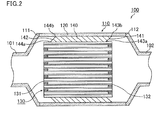
- Fig. 2 is a cross-sectional view that schematically illustrates an example of an exhaust gas purifying system of the first embodiment of the present invention.
- the exhaust gas purifying system 100 shown in Fig. 2 includes: an exhaust gas purifying apparatus 110; an inlet pipe 101 that is connected to one of ends of the exhaust gas purifying apparatus 110, and used for introducing exhaust gases into the exhaust gas purifying apparatus 110; and an exhaust pipe 102 that is connected to the other end of the exhaust gas purifying apparatus 110, and used for discharging the exhaust gases that have passed through the exhaust gas purifying apparatus 110 outside.
- the exhaust gas purifying apparatus 110 is provided with a gas inlet side 111 connected to the inlet pipe 101 and a gas outlet side 112 connected to the exhaust pipe 102.
- Fig. 3(a) is a perspective view that schematically illustrates an example of the exhaust gas purifying apparatus forming an exhaust gas purifying system in accordance with the first embodiment of the present invention.
- Fig. 3(b) is an A-A line cross-sectional view of the exhaust gas purifying apparatus shown in Fig. 3(a) .
- the exhaust gas purifying apparatus 110 shown in Fig. 3(a) and Fig. 3(b) , is provided with a metal casing 120, an exhaust gas treating body 130 housed in the metal casing 120, and a holding sealing material 140 that is placed between the exhaust gas treating body 130 and the metal casing 120.
- the holding sealing material 140 is a mat-shaped member containing inorganic fibers, and wound around the periphery of the exhaust gas treating body 130.
- the exhaust gas treating body 130 is held by the holding sealing material 140.
- the exhaust gas treating body 130 forming the exhaust gas purifying apparatus 110 is provided with an inlet-side end face 131 positioned on the gas inlet side 111 of the exhaust gas purifying apparatus 110 and an outlet-side end face 132 positioned on the gas outlet side 112 of the exhaust gas purifying apparatus 110.
- the holding sealing material 140 is provided with a first side face 141 positioned on the gas outlet side 112 of the exhaust gas purifying apparatus 110 and a second side face 142 positioned on the gas inlet side 111 of the exhaust gas purifying apparatus 110. Moreover, on the first side face 141 of the holding sealing material 140, a first slanting face is formed, and on the second side face 142 of the holding sealing material 140, a second slanting face is formed.
- the first slanting face formed on the first side face 141 of the holding sealing material 140 has a first inside end point 143a at which the holding sealing material 140 and the exhaust gas treating body 130 are made in contact with each other, and a first outside end point 143b at which the holding sealing material 140 and the metal casing 120 are made in contact with each other.
- the first inside end point 143a of the holding sealing material 140 is positioned closer the gas inlet side 111 of the exhaust gas purifying apparatus 110 than the first outside end point 143b of the holding sealing material 140.
- the first slanting face is tilted relative to the end face of the exhaust gas treating body 130, and directed toward the first outside end point 143b from the first inside end point 143a.
- the second slanting face formed on the second side face 142 of the holding sealing material 140 has a second inside end point 144a at which the holding sealing material 140 and the exhaust gas treating body 130 are made in contact with each other, and a second outside end point 144b at which the holding sealing material 140 and the metal casing 120 are made in contact with each other.
- the second inside end point 144a of the holding sealing material 140 is positioned closer the gas inlet side 111 of the exhaust gas purifying apparatus 110 than the second outside end point 144b of the holding sealing material 140.
- the second slanting face is tilted relative to the end face of the exhaust gas treating body 130, and directed toward the second outside end point 144b from the second inside end point 144a.
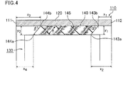
- Fig. 4 is a partially enlarged cross-sectional view that illustrates a portion in proximity to an inner circumference of a metal casing in the exhaust gas purifying apparatus forming the exhaust gas purifying system shown in Fig. 2 .
- a first angle On a cross section in parallel with the longitudinal direction of the exhaust gas purifying apparatus, of angles formed by a line segment connecting a first inside end point to a first outside end point and the inner circumference of the metal casing, an angle corresponding to an acute angle is referred to as "a first angle".
- an angle corresponding to an acute angle is referred to as "a second angle". That is, in the exhaust gas purifying apparatus 110 shown in Fig. 4 , the angle indicated by “ ⁇ ” is the first angle, and the angle indicated by “ ⁇ ” is the second angle.
- a distance from the gas outlet side 112 of the exhaust gas purifying apparatus 110 to the first outside end point 143b of the holding sealing material 140 is measured.
- a distance from the gas outlet side 112 of the exhaust gas purifying apparatus 110 to the first inside end point 143a of the holding sealing material 140 is measured.
- a distance between the metal casing 120 and the exhaust gas treating body 130 is measured.
- Second angle ⁇ (°) arctan [y 2 /(x 3 - x 4 )] ...
- the first angle (on the cross section in parallel with the longitudinal direction of the exhaust gas purifying apparatus, of angles formed by a line segment connecting a first inside end point to a first outside end point and the inner circumference of the metal casing, the angle corresponding to an acute angle) is preferably set to 25 to 89.5° from the viewpoint of holding strength of the holding sealing material.
- the second angle (on the cross section in parallel with the longitudinal direction of the exhaust gas purifying apparatus, of angles formed by a line segment connecting a second inside end point to a second outside end point and the inner circumference of the metal casing, an angle corresponding to an acute angle) is preferably set to 25 to 89.5° from the viewpoint of holding strength of the holding sealing material.
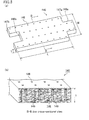
- FIG. 5(a) is a perspective view that schematically illustrates an example of the holding sealing material in the exhaust gas purifying apparatus forming the exhaust gas purifying system of the first embodiment of the present invention
- Fig. 5(b) is a B-B line cross-sectional view of the holding sealing material illustrated in Fig. 5(a)
- the holding sealing material 140 shown in Fig. 5(a) and Fig. 5(b) contains inorganic fibers 149 such as alumina-silica fibers, and formed into a substantially rectangular flat plate shape on a plan view having predetermined length (indicated by arrow "L" in Fig.
- a projected portion 148a is formed on one end face 147a, and a recessed portion 148b, which has a shape to which the projected portion 148a is fitted when the holding sealing material 140 is folded so that the end face 147a and the end face 147b are made in contact with each other, is formed on the other end face 147b.
- Such a holding sealing material can be manufactured by allowing the inorganic fibers to be entangled with one another by the use of a spinning method.
- the holding sealing material is preferably a needled mat obtained by carrying out a needling treatment on a base mat containing inorganic fibers.
- the needling treatment refers to a treatment in which needles or the like serving as a fiber entangling means are inserting and withdrawing to and from the base mat.
- inorganic fibers having a comparatively long fiber length are three-dimensionally entangled with one another. For this reason, it is possible to prevent the inorganic fibers from being split, and consequently to improve the strength of the needled mat.
- the holding sealing material has a plurality of needle marks formed by the needling treatment.
- the holding sealing material 140 shown in Fig. 5(a) and Fig. 5(b) is an example that has a plurality of needle marks 146.
- Each needle mark 146 includes inorganic fibers 149 that are aligned in a thickness direction of the holding sealing material and entangled with one another.
- the holding sealing material 140 In the case when the inorganic fibers of the holding sealing material are aligned in a predetermined direction, it is considered that in the exhaust gas purifying apparatus, push-out intensity applied to the exhaust gas treating body and metal casing by the holding sealing material is increased in directions of the needle mark (directions indicated by a double-headed arrow "f" in Fig. 5(b) ) that is, in a direction in which the inorganic fibers are aligned.
- the holding sealing material 140 In the holding sealing material 140, the holding sealing material 140 is in such a state as to be stitched in its thickness direction with the mutually entangled inorganic fibers 149, centered on the needle marks 146.
- an area having no needle marks 146 formed therein is formed, with the inorganic fibers 149 that are not aligned in a specific direction being entangled with one another comparatively weakly, so that it is formed into a nonwoven fabric.
- the area near the needle marks 146 has a higher density in the inorganic fibers 149 than that in the area having no needle marks 146 formed therein.
- the needle marks are preferably formed in a direction diagonal to the thickness direction of the holding sealing material. More specifically, in the exhaust gas purifying system prior to allowing exhaust gases to flow therein, the needle marks are preferably made substantially in parallel with a first slanting face and a second slanting face formed on the holding sealing material.
- Fig. 4 shows an example in which the holding sealing material 140 forming the exhaust gas purifying apparatus 110 has the plurality of needle marks 146 formed in a direction diagonal to the thickness direction of the holding sealing material 140.
- the holding sealing material 140 is allowed to push out the exhaust gas treating body 130 and the metal casing 120 in direction "f" of the needle marks substantially in parallel with the first slanting face and the second slanting face.
- a binder may be added to the holding sealing material.
- the binder added to the holding sealing material allows the inorganic fibers forming the holding sealing material to stick to one another. Therefore, by using the binder, the size of the holding sealing material can be reduced upon being stuffed to the metal casing, or the inorganic fibers can be prevented from scattering.
- the binder since the directions of needle marks can be easily maintained so that the force to be applied by the holding sealing material to push out the exhaust gas treating body and the metal casing is increased. As a result, the holding strength of the holding sealing material can be improved.
- the method for adding a binder to the holding sealing material for example, a method in which a predetermined amount of a binder solution is sprayed onto the holding sealing material by using a spray or the like so that the binder is adhered to the holding sealing material, or a method in which the holding sealing material is impregnated with a binder solution may be used.
- an emulsion prepared by dispersing an organic binder such as an acrylic resin in water, may be used.
- an inorganic binder such as alumina sol may be contained in the binder solution,.
- binder content The amount of the binder to be added to the holding sealing material (hereinafter, referred to as "binder content”) is preferably set to 10% by weight or less, more preferably, to 0.5 to 6.0% by weight, most preferably, to 1.0 to 2.0% by weight, from the viewpoint of improving the holding strength of the holding sealing material.
- Fig. 6 (a) is a perspective view that schematically shows an example of the exhaust gas treating body in the exhaust gas purifying apparatus forming an exhaust gas purifying system in accordance with the first embodiment of the present invention.
- Fig. 6(b) is a C-C line cross-sectional view of the exhaust gas treating body shown in Fig. 6(a) .
- an exhaust gas treating body 130 mainly includes a porous ceramic material, such as cordierite, and has a substantially round pillar-shape. Moreover, a coat layer 136 is formed on the outer periphery of the exhaust gas treating body 130 so as to reinforce the outer peripheral portion of the exhaust gas treating body 130, adjust the shape and improve the heat insulating property of the exhaust gas treating body 130. In this case, the coat layer may be formed, if necessary.
- the exhaust gas treating body 130 shown in Fig. 6(a) is prepared as a honeycomb structured body in which a large number of cells 133 are placed in parallel with one another in the longitudinal direction (in Fig. 6(a) , a direction indicated by a double-headed arrow "a"), with a cell wall 135 interposed therebetween. Either one of ends of each cell 133 is sealed with a plug material 134.
- the exhaust gas treating body functions as a filter (honeycomb filter) for purifying PMs contained in exhaust gases.
- the exhaust gas purifying method in which the honeycomb filter is used as the exhaust gas treating body will be described later.
- Fig. 7 is a perspective view that schematically shows an example of the metal casing in the exhaust gas purifying apparatus forming the exhaust gas purifying system of the first embodiment of the present invention.
- the metal casing 120 shown in Fig. 7 is mainly made of metal such as stainless steel, and has a substantially cylindrical shape.
- the inner diameter of the metal casing 120 is made slightly shorter than a combined length of the diameter of the end face of the exhaust gas treating body 130 shown in Fig. 6(a) and Fig. 6(b) and the thickness of the holding sealing material 140 wound around the exhaust gas treating body 130.
- the length of the metal casing 120 is made slightly longer than the length in the longitudinal direction of the exhaust gas treating body 130 shown in Fig. 6(a) and Fig. 6(b) .
- the length of the metal casing may be substantially the same as the length in the longitudinal direction of the exhaust gas treating body.
- Fig. 8(a) is a perspective view that schematically shows an example of the inlet pipe forming the exhaust gas purifying system of the first embodiment of the present invention.
- Fig. 8(b) is a perspective view that schematically shows an example of the exhaust pipe forming the exhaust gas purifying system of the first embodiment of the present invention.
- the inlet pipe 101 shown in Fig. 8(a) is mainly made of metal such as stainless steel, and has a substantially cylindrical shape. As shown in Fig.
- the outer diameter (inner diameter) of one end face 103a of the inlet pipe 101 is made substantially the same as the outer diameter (inner diameter) of the metal casing 120 shown in Fig. 7 .
- the outer diameter (inner diameter) of the other end face 103b of the inlet pipe 101 is made smaller than the outer diameter (inner diameter) of the end face of the metal casing 120 shown in Fig. 7 .
- the shape of one end face 103a of the inlet pipe 101 and the proximity thereof has a tapered shape that is narrowed from one end face 103a toward the other end face 103b.
- the other end face 103b of this inlet pipe 101 is coupled to an internal combustion engine, after having been further connected to an exhaust gas pipe, if necessary.
- the exhaust pipe 102 shown in Fig. 8(b) is mainly made of metal such as stainless steel, and has a substantially cylindrical shape. As shown in Fig. 8(b) , the outer diameter (inner diameter) of one end face 104a of the exhaust pipe 102 is made substantially the same as the outer diameter (inner diameter) of the metal casing 120 shown in Fig. 7 . Moreover, the outer diameter (inner diameter) of the other end face 104b of the exhaust pipe 102 is made smaller than the outer diameter (inner diameter) of the end face of the metal casing 120 shown in Fig. 7 .
- the shape of one end face 104a of the exhaust pipe 102 and the proximity thereof has a tapered shape that is narrowed from one end face 104a toward the other end face 104b.
- the other end face 104b of this exhaust pipe 102 is coupled to the outside.
- the exhaust gas purifying system 100 shown in Fig. 1(a) and Fig. 1(b) has a structure in which the honeycomb filter shown in Fig. 6(a) and Fig. 6(b) is used as the exhaust gas treating body 130.
- exhaust gases are indicated as "G 1 ", and the flow of exhaust gases is indicated by an arrow), that is, toward the gas outlet side 112 of the exhaust gas purifying apparatus 110 so that the first side face 141 of the holding sealing material 140 is made substantially parallel to the outlet side end face 132 of the exhaust gas treating body 130.
- the second slanting face formed on the second side face 142 of the holding sealing material 140 is shifted toward the gas outlet side 112 of the exhaust gas purifying apparatus 110 so that the second side face 142 of the holding sealing material 140 is made substantially parallel to the inlet side end face 131 of the exhaust gas treating body 130.
- the holding strength of the holding sealing material is maximized when the first side face and the second side face of the holding sealing material are made substantially parallel to the end face of the exhaust gas treating body.
- the exhaust gas purifying system of the present embodiment is designed so that, not until at least the first side face and the second side face of the holding sealing material have been made substantially in parallel with the end face of the exhaust gas treating body, the exhaust gas treating body is held by the holding sealing material so as not to be shifted thereafter even upon receipt of flow-in exhaust gases.
- the exhaust gases G 1 flowing into the exhaust gas purifying apparatus 110 from the gas inlet side 111 of the exhaust gas purifying apparatus 110 are further allowed to flow into one of the cells 133a of the exhaust gas treating body 130, with the end portion on the outlet side end face 132 being sealed.
- the exhaust gases G 1 pass through the cell wall 135 that separates the corresponding one of the cells 133a and the other cell 133b whose end portion on the inlet side end face 131 of the exhaust gas treating body 130 is sealed.
- PMs in the exhaust gases are captured by the cell wall 135 so that the exhaust gases G 1 are purified.
- the exhaust gases G 1 thus purified are allowed to flow into the other cell 133b and discharged outside of the exhaust gas purifying apparatus 110 from the gas outlet side 112 of the exhaust gas purifying apparatus 110. Thereafter, the exhaust gases G 1 are discharged outside through the exhaust pipe 102. In this manner, the cell wall 135 that separates one of the cells 133a and the other cell 133b is allowed to function as a filter.
- the manufacturing method of the exhaust gas purifying system of the present embodiment includes a stuffing step (a press-fitting step) and a connecting step.
- Fig. 9(a) is a perspective view that schematically shows an example of the stuffing step of the first embodiment of the present invention.
- the stuffing direction is indicated by an arrow "X".
- a wound body 150 in which the holding sealing material 140 is wound on the periphery of the exhaust gas treating body 130 is prepared.
- the wound body 150 can be manufactured by winding the holding sealing material 140 on the outer periphery of the exhaust gas treating body (honeycomb structured body) 130, shown in Fig. 6(a) and Fig. 6(b) , with a projected portion 148a and a recessed portion 148b of the holding sealing material 140 shown in Fig. 5(a) being fitted to each other.
- the wound body is stuffed into a metal casing to manufacture an exhaust gas purifying apparatus (stuffing step).
- stuffing step with the second side face 142 of the holding sealing material 140 serving as a leading portion relative to the proceeding direction of the stuffing, the wound body 150 is pressed from the first side face 141 of the holding sealing material 140 so that the wound body 150 is stuffed to a predetermined position inside the metal casing 120.
- the stuffing step shown in Fig. 9(a) corresponds to a method for stuffing the wound body 150 into the metal casing 120 by using a stuffing jig 80.
- the stuffing jig 80 has a substantially cylindrical shape as a whole, with its inside being expanded from one end to the other end in a tapered state.
- One end of the stuffing jig 80 forms an end portion on a shorter diameter side 81 having an inner diameter corresponding to a diameter slightly smaller than the inner diameter of the metal casing 120.
- the other end of the stuffing jig 80 forms an end portion on a longer diameter side 82 having at least an inner diameter corresponding to the outer diameter of the wound body 150.
- the wound body 150 can be easily stuffed into the metal casing 120.
- the method for stuffing the wound body into the metal casing is not particularly limited, and, for example, a method may be used in which, by pushing the wound body with the hand, the wound body is stuffed into the metal casing.
- the metal casing may be compressed from the outer peripheral side so as to shorten the inner diameter of the metal casing so that the wound body may be held.
- Fig. 9(b) is a partially exploded perspective cross-sectional view that schematically shows an exhaust gas purifying apparatus manufactured by the stuffing step shown in Fig. 9(a) .
- a shearing force is exerted between the first main surface 145a of the holding sealing material 140 in contact with the exhaust gas treating body 130 and the second main surface 145b of the holding sealing material 140 in contact with the metal casing 120, with the result that the position of the first main surface 145a and the position of the second main surface 145b are mutually displaced from each other to cause the holding sealing material 140 to be deformed.
- the exhaust gas purifying apparatus 110 shown in Fig. 9(b) the first side face 141 and the second side face 142 of the holding sealing material 140 are brought into a tilted state.
- FIG. 9(c) is a perspective view that schematically shows an example of a connecting step of the first embodiment of the present invention.
- the direction of the exhaust gas purifying apparatus is reversed to that of Fig. 9(b) .
- the connecting step first, of the ends of the exhaust gas purifying apparatus 110, one of the ends closer to the second side face 142 of the holding sealing material 140 than to the first side face 141 of the holding sealing material 140 is connected to an inlet pipe 101 by welding.
- the other end closer to the first side face 141 of the holding sealing material 140 than to the second side face 142 of the holding sealing material 140 is connected to an exhaust pipe 102 by welding. Additionally, in place of the welding, another joining method, such as a screw or a predetermined metal member, may be used.
- the exhaust gas purifying system 100 shown in Fig. 2 can be manufactured.
- the end closer to the second side face 142 of the holding sealing material 140 than to the first side face 141 of the holding sealing material 140 is allowed to form the gas inlet side 111 of the exhaust gas purifying apparatus 110, while the end closer to the first side face 141 of the holding sealing material 140 than to the second side face 142 of the holding sealing material 140 is allowed to form the gas outlet side 112 of the exhaust gas purifying apparatus 110.
- the needled mat was cut to prepare a cut needled mat having a size of 266 mm (in length) ⁇ 83.5 mm (in width) on a plan view.
- a binder solution was sprayed onto the cut needled mat by using a spray so as to be set to 1.0% by weight relative to the amount of alumina fibers of the cut needled mat so that the binder was uniformly adhered to the entire needled mat.
- an acrylic latex emulsion prepared by sufficiently dispersing an acrylic resin in water was used as the binder solution.
- a honeycomb structured body (exhaust gas treating body) mainly including a porous ceramic material, having a round pillar shape with a size of 80 mm in diameter x 95 mm in length, was prepared according to a conventionally known method.
- the holding sealing material manufactured in process (1) was wound around the outer peripheral portion of the prepared exhaust gas treating body without any gap so as to allow a projected portion and a recessed portion on the ends of the holding sealing material to be fitted to each other so that a wound body was manufactured.
- the wound body thus manufactured has a first side face and a second side face.
- a metal casing, made of stainless steel, having a cylindrical shape with a size of 88 mm (inner diameter) x 115 mm (overall length) was prepared.
- a stuffing jig having a shape as shown in Fig. 9(a) was prepared so as to stuff the wound body into the metal casing.
- the end portion on the shorter diameter side of the prepared stuffing jig was fitted into one end of the metal casing, and the two members were secured to each other.
- the wound body was pressed from the first side face side of the holding sealing material so that the wound body was stuffed into the metal casing. More specifically, with the wound body (the second side face side of the holding sealing material) pressed onto the end portion of the longer diameter side of the stuffing jig, by pushing the wound body from the first side face side of the holding sealing material, the wound body was stuffed so that the entire wound body was positioned inside the metal casing; thus, an exhaust gas purifying apparatus was manufactured.
- the gap bulk density of the holding sealing material in the manufactured exhaust gas purifying apparatus is 0.35 g/cm 3 .
- the end that was closer to the second side face of the holding sealing material than to the first side face of the holding sealing material was connected to an inlet pipe, and the end that was closer to the first side face of the holding sealing material than to the second side face of the holding sealing material was connected to an exhaust pipe so that an exhaust gas purifying system was manufactured.
- the exhaust gas purifying system of Example 1 corresponds to the exhaust gas purifying system 100 shown in Fig. 2 .
- a first slanting face was formed on the first side face of the holding sealing material, and a second slanting face was formed on the second side face of the holding sealing material.
- the first slanting face formed on the first side face of the holding sealing material has a first inside end point at which the holding sealing material and the exhaust gas treating body are made in contact with each other and a first outside end point at which the holding sealing material and the metal casing are made in contact with each other.
- the first inside end point of the holding sealing material is positioned closer to the gas inlet side of the exhaust gas purifying apparatus than the first outside end point of the holding sealing material, and the first slanting face is directed toward the first outside end point from the first inside end point.
- the second slanting face formed on the second side face of the holding sealing material has a second inside end point at which the holding sealing material and the exhaust gas treating body are made in contact with each other and a second outside end point at which the holding sealing material and the metal casing are made in contact with each other.
- the second inside end point of the holding sealing material is positioned closer to the gas inlet side of the exhaust gas purifying apparatus than the second outside end point of the holding sealing material, and the second slanting face is directed toward the second outside end point from the second inside end point.
- 61.2° was obtained as the first angle.
- Example 2 By carrying out the same processes as those of Example 1 except that by altering the concentration of the binder to be adhered to the cut needled mat, the binder content of the holding sealing material was set to 6.0% by weight (Example 2) as well as to 10% by weight (Example 3) so that holding sealing materials were manufactured. Moreover, by using these holding sealing materials, wound bodies were manufactured in the same manner as in Example 1 so that exhaust gas purifying apparatuses were manufactured. By using the exhaust gas purifying apparatuses thus manufactured, the inlet pipe and exhaust pipe were connected thereto in the same manner as in Example 1 so that exhaust gas purifying systems were manufactured. The gap bulk density, the binder content and the first angle of the holding sealing material in each of the exhaust gas purifying systems of Example 2 and Example 3 are shown in Table 1.
- Example 1 The same processes as those of Example 1 were carried out except that the bulk density of the holding sealing material was altered so as to set the gap bulk density of the holding sealing material in the exhaust gas purifying apparatus forming the exhaust gas purifying system to values indicated in Table 1 so that holding sealing materials were manufactured. Moreover, by using these holding sealing materials, the same processes as those of Example 1 were carried out so that wound bodies were manufactured, and exhaust gas purifying apparatuses were manufactured. By using the exhaust gas purifying apparatuses thus manufactured, the inlet pipe and exhaust pipe were connected thereto in the same manner as in Example 1 so that exhaust gas purifying systems were manufactured. The gap bulk density, the binder content and the first angle of the holding sealing material in each of the exhaust gas purifying systems of Examples 4 to 8 are shown in Table 1.
- Example 1 By carried out the same processes as those of Example 1 except that no needling treatment was carried out on a base mat upon manufacturing a holding sealing material, a holding sealing material was manufactured. Moreover, by using this holding sealing material, the same processes as those of (Example 1 were carried out so that a wound body was manufactured, and an exhaust gas purifying apparatus was manufactured. By using the exhaust gas purifying apparatus thus manufactured, the inlet pipe and exhaust pipe were connected thereto in the same manner as in Example 1 so that an exhaust gas purifying system was manufactured. The gap bulk density, the binder content and the first angle of the holding sealing material in the exhaust gas purifying system of Example 9 are shown in Table 1.
- Example 1 With respect to the exhaust gas purifying apparatus manufactured in Example 1, in a manner opposite to that of Example 1, of the ends of the exhaust gas purifying apparatus, the end that was closer to the first side face of the holding sealing material than to the second side face of the holding sealing material was connected to an inlet pipe, and the end that was closer to the second side face of the holding sealing material than to the first side face of the holding sealing material was connected to an exhaust pipe so that an exhaust gas purifying system was manufactured.
- the exhaust gas purifying system of Comparative Example 1 corresponds to the exhaust gas purifying system 200 shown in Fig. 21 , manufactured by a conventional method.
- a first slanting face was formed on the first side face of the holding sealing material, and a second slanting face was formed on the second side face of the holding sealing material.
- both of the first side face and the second side face are tilted in a direction reversed to that of the exhaust gas purifying system of Example 1.
- the gap bulk density, the binder content and the first angle of the holding sealing material in the exhaust gas purifying system of Comparative Example 1 are shown in Table 1.
- the gap bulk density and the binder content of the holding sealing material in the exhaust gas purifying system of Comparative Example 1 are the same as those values in Example 1.
- the first angle of the holding sealing material in the exhaust gas purifying system of Comparative Example 1 is the same as that of Example 1; however, the direction of the angle is opposite to that of Example 1.
- the first angle of the holding sealing material is indicated by a minus value.
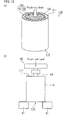
- Fig. 10(a) is a perspective view that schematically illustrates a method for measuring a push-out intensity
- Fig. 10 (b) is a front view that schematically shows a push-out intensity tester.
- FIG. 10(b) a method for measuring the push-out intensity of the exhaust gas purifying apparatus in each of the exhaust gas purifying systems of the respective Examples was illustrated.
- the exhaust gas purifying apparatus 110 of each of the exhaust gas purifying systems of the respective Examples was mounted on a base 61, with a gas inlet side 111 of the exhaust gas purifying apparatus 110 facing up.
- a push-out load (pressing velocity 1 mm/min) was applied onto the exhaust gas treating body 130 by a push-out jig 62.
- the maximum value of the push-out load (N) up to a point of time at which the wound body 150 (the exhaust gas treating body 130 with a holding sealing material 140 wound therearound) had been pushed out was measured.
- the push-out jig 62 was made of aluminum, with a diameter of a load portion 63 in contact with the wound body 150 being set to 30 mm.
- a value obtained by dividing this maximum value of the push-out load (N) by an area (cm 2 ) of the holding sealing material was defined as a push-out intensity (N/cm 2 ) serving as a holding strength between the holding sealing material and the metal casing.
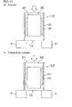
- FIG. 11 (b) an exhaust gas purifying apparatus 210 of each of the exhaust gas purifying systems of the respective Comparative Examples was mounted on a base 61, with a gas inlet side 211 of the exhaust gas purifying apparatus 210 facing up, and the push-out intensity was measured by using the same method as described earlier.
- Fig. 11(a) is a cross-sectional view that schematically illustrates a state in which the push-out intensity of the exhaust gas purifying apparatus is measured in the exhaust gas purifying system of each of Examples, and Fig.
- 11(b) is a cross-sectional view that schematically illustrates a state in which the push-out intensity of the exhaust gas purifying apparatus is measured in the exhaust gas purifying system of each of Comparative Examples.
- an instron universal tester (model 5582) was used.
- the push-out intensities of the exhaust gas purifying apparatuses of the respective exhaust gas purifying systems of Examples 1 to 9 were respectively obtained as values: 4.58 N/cm 2 , 5.42 N/cm 2 , 6.38 N/cm 2 , 2.29 N/cm 2 , 3.33 N/cm 2 , 5.58 N/cm 2 , 6.92 N/cm 2 , 8.29 N/cm 2 , and 4.20 N/cm 2 .
- the push-out intensities of the exhaust gas purifying apparatuses of the respective exhaust gas purifying systems of Comparative Examples 1 to 7 were respectively obtained as values: 3.22 N/cm 2 4.11 N/cm 2 , 5.17 N/cm 2 , 1.42 N/cm 2 , 2.11 N/cm 2 , 4.02 N/cm 2 , and 4.71 N/cm 2 .
- Table 1 shows the results of measurements on the push-out intensity of the exhaust gas purifying apparatus of each of the exhaust gas purifying systems of the respective Examples and Comparative Examples.
- Fig. 12 is a perspective view that schematically illustrates a method for measuring the amount of scattered fibers.
- the method for measuring the amount of scattered fibers of the exhaust gas purifying apparatus in the exhaust gas purifying system of Example 1 is shown. As shown in Fig.
- an exhaust gas purifying apparatus 110 with an end face of an exhaust gas treating body 130 being subjected to a masking treatment was mounted on paper 71, with the gas inlet side 111 of the exhaust gas purifying apparatus 110 facing down.
- an impact was applied onto the exhaust gas purifying apparatus110 by using a hammer 72 so that the weight (mg) of fibers dropped on the paper 71 was measured by using an electronic scale.
- the weight of the fibers was defined as an amount of scattered fibers (mg).
- FIG. 13 (b) an exhaust gas purifying apparatus 210 with an end face of an exhaust gas treating body 230 being subjected to a masking treatment was mounted on paper 71, with the gas inlet side 211 of the exhaust gas purifying apparatus 210 facing down, and the amount of scattered fibers was measured by using the same method as described above.
- Fig. 13(a) is a cross-sectional view that schematically illustrates a state in which the amount of scattered fibers of the exhaust gas purifying apparatus is measured in the exhaust gas purifying system in Example 1
- Fig. 13(b) is a cross-sectional view that schematically illustrates a state in which the amount of scattered fibers of the exhaust gas purifying apparatus is measured in the exhaust gas purifying system in Comparative Example 1.
- the amount of scattered fibers of the exhaust gas purifying apparatus in the exhaust gas purifying system of Example 1 was 0.267 mg.
- the amount of scattered fibers of the exhaust gas purifying apparatus in the exhaust gas purifying system of Comparative Example 1 was 1.30 mg.
- Fig. 14 is a graph that shows the results of measurements of the push-out intensity in Example 1 and Comparative Example 1.
- Fig. 15 is a graph that indicates a relationship between a binder content in the holding sealing material and the push-out intensity based upon measured results of the push-out intensity in Example 1 to Example 3, as well as in Comparative Example 1 to Comparative Example 3.
- Fig. 14 is a graph that shows the results of measurements of the push-out intensity in Example 1 and Comparative Example 1.
- Fig. 15 is a graph that indicates a relationship between a binder content in the holding sealing material and the push-out intensity based upon measured results of the push-out intensity in Example 1 to Example 3, as well as in Comparative Example 1 to Comparative Example 3.
- Fig. 14 is a graph that shows the results of measurements of the push-out intensity in Example 1 and Comparative Example 1.
- Fig. 15 is a graph that indicates a relationship between a binder content in the holding sealing material and the push-out intensity based upon measured results of the push-out
- Fig. 16 is a graph that indicates a relationship between a gap bulk density of the holding sealing material and the push-out intensity based upon measured results of the push-out intensity in Example 1 and Examples 4 to 8, as well as in Comparative Example 1 and Comparative Examples 4 to 7.
- Fig. 17 is a graph that shows the results of measurements of the push-out intensity in Example 1 and Example 9.
- Fig. 18 is a graph that shows the results of measurements of the amount of scattered fibers in Example 1 and Comparative Example 1.
- Example 1 Holding Sealing Material Exhaust Gas Purifying Apparatus Gap Bulk Density (g/cm 3 ) Binder Content (% by weight) First Angle (degrees) Needling Treatment Push-out Intensity (N/cm 2 )
- Example 1 0.35 1.0 61.2 Treated 4.58
- Example 2 0.35 6.0 57.8 Treated 5.42
- Example 3 0.35 10 69.2 Treated 6.38
- Example 4 0.27 1.0 70.5 Treated 2.29
- Example 5 0.30 1.0 67.6 Treated 3.33
- Example 6 0.38 1.0 56.8 Treated 5.58
- Example 7 0.42 1.0 49.9 Treated 6.92
- Example 9 0.35 1.0 81.5 Not treated 4.20 Comparative Example 1 0.35 1.0 -61.2 Treated 3.22 Comparative Example 2 0.35 6.0 -57.8 Treated 4.11 Comparative Example 3 0.35 10 -69.2 Treated 5.17 Comparative Example 4 0.27 1.0 -7
- the push-out intensity in Examples had a value greater than that of the push-out intensity in Comparative Examples. Based upon the results of these, it is considered that, by adding a binder to the holding sealing material forming the exhaust gas purifying apparatus, the holding strength of the holding sealing material can be improved. Moreover, in the exhaust gas purifying system, by tilting the first side face of the holding sealing material to a direction reversed to that of an exhaust gas purifying system manufactured by a conventional method, the effect for improving the holding strength of the holding sealing material is considered to be exerted irrespective of the content of the binder.
- Fig. 15 indicates that as the binder content of the holding sealing material increases, the push-out intensity is improved.
- Fig. 19 indicates that as the binder content of the holding sealing material increases, the rate of increase with push-out intensity reduces.
- the push-out intensity in Examples had a value greater than that of the push-out intensity of Comparative Examples. Based upon the results of these, it is considered that in the exhaust gas purifying system, by tilting the first side face of the holding sealing material to a direction reversed to the direction of an exhaust gas purifying system manufactured by a conventional method, the effect for improving the holding strength of the holding sealing material is considered to be exerted irrespective of the gap bulk density of the holding sealing material. Moreover, as indicated by Fig. 16 , the push-out intensity is considered to be increased as the gap bulk density of the holding sealing material becomes greater.
- the push-out intensity in Example 1 in which the holding sealing material was subjected to the needling treatment had a value greater than that of the push-out intensity of Example 9 in which the holding sealing material was not subjected to the needling treatment.
- This fact indicates that by carrying out the needling treatment on the holding sealing material forming the exhaust gas purifying apparatus, the inorganic fibers forming the holding sealing material are aligned in a direction perpendicular to the surface of the holding sealing material so that the holding strength of the holding sealing material is considered to be further improved.
- Fig. 18 indicates that the amount of scattered fibers in Example 1 is extremely smaller than the amount of scattered fibers in Comparative Example 1. This fact indicates that in the exhaust gas purifying system, by tilting the first side face of the holding sealing material to a direction reversed to that of an exhaust gas purifying system manufactured by a conventional method, the inorganic fibers that form the holding sealing material are constrained by the holding strength of the holding sealing material so that the amount of scattered inorganic fibers toward the internal combustion engine side from the gas inlet side of the exhaust gas purifying apparatus can be reduced.
- the metal casing in the exhaust gas purifying apparatus forming the exhaust gas purifying system may have distinguished portions as to a gas inlet side forming the gas inlet side of the exhaust gas purifying apparatus and a gas outlet side forming the gas outlet side of the exhaust gas purifying apparatus.
- the exhaust gas purifying apparatus having the first slanting face formed on the first side face of the holding sealing material and the second slanting face formed on the second side face of the holding sealing material can be manufactured so that an exhaust gas purifying system can be manufactured by using such an exhaust gas purifying apparatus.
- FIGs. 20(a) to 20(c) the following description will discuss a method for manufacturing the exhaust gas purifying apparatus forming the exhaust gas purifying system of the present invention, when there are distinguished gas inlet side and gas outlet side in the metal casing forming the exhaust gas purifying apparatus.
- an arrangement step is further carried out in which the exhaust gas treating body around which the holding sealing material has been wound is arranged, with the second side face of the holding sealing material serving as a leading portion relative to an proceeding direction of the stuffing, so that the first side face of the holding sealing material is positioned on the gas outlet side of the metal casing, with the second side face of the holding sealing material being positioned on the gas inlet side of the metal casing.
- Fig. 20(a) is a perspective view that schematically shows an example of the arrangement step in accordance with the embodiment of the present invention.
- the stuffing direction is indicated by an arrow "Y".
- a wound body 50 in which a holding sealing material 40 is wound on the periphery of an exhaust gas treating body 30 is prepared. Since the method for manufacturing the wound body has been explained in the first embodiment of the present invention, the description thereof is omitted.
- the wound body is arranged in a predetermined orientation relative to the metal casing (arrangement step).
- the wound body 50 is arranged, with the second side face 42 of the holding sealing material 40 serving as a leading portion relative to an proceeding direction of the stuffing, so that the first side face 41 of the holding sealing material 40 is positioned on the gas outlet side 22 of the metal casing 20, with the second side face 42 of the holding sealing material 40 being positioned on the gas inlet side 21 of the metal casing 20.
- Fig. 20(b) is a partially exploded perspective cross-sectional view that schematically shows an example of the stuffing step in accordance with the embodiment of the present invention.
- the stuffing direction is indicated by an arrow " ⁇ ".
- the stuffing step by pushing the wound body 50 from the first side face 41 of the holding sealing material 40, the wound body 50 is stuffed into a predetermined position inside the metal casing 20.
- a method using the stuffing jig explained in the first embodiment of the present invention may be used.
- FIG. 20(c) is a partially exploded perspective cross-sectional view that schematically shows an exhaust gas purifying apparatus manufactured through the arrangement step shown in Fig. 20(a) and the stuffing step shown in Fig. 20(b) .
- the exhaust gas treating body 30 is provided with an inlet side end face 31 positioned on the gas inlet side 21 of the metal casing 20 and an outlet side end face 32 positioned on the gas outlet side 22 of the metal casing 20.
- a shearing force is exerted between a first main face 45a of the holding sealing material 40 in contact with the exhaust gas treating body 30 and a second main face 45b of the holding sealing material 40 in contact with the metal casing 20, so that the mutual positions of the first main face 45a and the second main face 45b are displaced to cause the holding sealing material 40 to be deformed.
- the first side face 41 and the second side face 42 of the holding sealing material 40 are brought into a tilted state.
- an inlet pipe is connected to the gas inlet side of the metal casing forming the exhaust gas purifying apparatus and an exhaust pipe is connected to the gas outlet side of the metal casing forming the exhaust gas purifying apparatus so that an exhaust gas purifying system having the structure of the present invention can be manufactured.
- the first slanting face is formed on the first side face of the holding sealing material
- the second slanting face is formed on the second side face of the holding sealing material.
- the method in which the first slanting face is formed on the first side face of the holding sealing material, while the second slanting face is not formed on the second side face of the holding sealing material for example, a method in which the side face of the holding sealing material is cut by using a cutting tool such as a cutter may be used.
- the first slanting face and the second slanting face formed on the holding sealing material are not particularly limited in its cross-sectional shape, as long as the inside end point and the outside end point of the holding sealing material satisfy the positional relationship explained in the first embodiment of the present invention, and any desired shapes formed by using lines, such as a straight line, a curved line and a polygonal line, may be used.
- the first slanting face to be formed on the holding sealing material is not necessarily required to be formed over the entire portion of the first side face of the holding sealing material.
- the first slanting face may be formed only on one portion of the first side face of the holding sealing material.
- the second slanting face to be formed on the holding sealing material is not necessarily required to be formed over the entire portion of the second side face of the holding material, and may be formed only on one portion of the second side face of the holding sealing material.
- the width of the holding sealing material is set to be shorter than the length in the longitudinal direction of the exhaust gas treating body.
- the width of the holding sealing material may be made substantially the same as the length in the longitudinal direction of the exhaust gas treating body, or may be made longer than the length in the longitudinal direction of the exhaust gas treating body.
- the first inside end point and the second inside end point are referred to as the first inside end point and the second inside end point respectively.
- the shapes of the recessed portion and the projected portion formed on the end faces of the holding sealing material are not particularly limited as long as the corresponding shapes allow the recessed portion and the projected portion to be fitted to each other, and in the case when one set of the recessed portion and projected portion is prepared, a projected portion that protrudes over a size ranging from 20 mm in width ⁇ 20 mm in length to 100 mm in width x 100 mm in length is preferably formed on one portion of one of end faces thereof, with a recessed portion having a corresponding shape to be fitted thereto being preferably formed on one portion of the other end face.
- inorganic fibers forming the holding sealing material not limited to the aforementioned inorganic fibers containing alumina and silica, inorganic fibers containing another inorganic compound may be used. Moreover, of alumina and silica, the inorganic fibers containing only alumina or the inorganic fibers containing only silica may be used.
- additives such as CaO, MgO and ZrO 2
- silica in addition to silica, for example, additives, such as CaO, MgO and ZrO 2 , may be contained therein.
- the average fiber length of the inorganic fibers forming the holding sealing material is preferably set to 0.5 to 10 cm, more preferably, to 1 to 8 cm.
- the average fiber diameter of the inorganic fibers forming the holding sealing material is preferably set to 1 to 20 ⁇ m, more preferably, to 3 to 10 ⁇ m.
- the weight per unit area of the holding sealing material is preferably set to 500 to 5000 g/m 2 , more preferably, to 1000 to 4000 g/m 2 .
- the bulk density (bulk density of the holding sealing material prior to the stuffing of the wound body to the metal casing) of the holding sealing material is preferably set to 0.10 to 0.30 g/cm 3 .
- the thickness of the holding sealing material is preferably set to 6 to 31 mm, more preferably, to 8 to 20 mm.
- the holding sealing material is prepared as a needled mat having been subjected to a needling treatment.
- the holding sealing material may be preferably subjected to the needling treatment, or may not be subjected to the needling treatment.
- the needling treatment may be carried out over the entire base mat including inorganic fibers, or may be carried out on one portion of the base mat.
- an organic binder contained in a binder solution to be used upon manufacturing the holding sealing material for example, an acrylic resin, rubber such as acrylic rubber, an water soluble organic polymer, such as carboxymethyl cellulose, or polyvinyl alcohol, a thermoplastic resin, such as styrene resin, and a thermosetting resin, such as an epoxy resin, may be used.
- acrylic resin, acrylonitrile-butadiene rubber, and styrene-butadiene rubber are in particular preferably used.
- the amount of the organic binder to be blended is preferably set to 15% by weight or less relative to the total weight of the inorganic fibers, the organic binder and the inorganic binder.
- the binder solution may contain a plurality of kinds of the aforementioned organic binders. Moreover, as the binder solution, in addition to a latex formed by dispersing the organic binder in water, a solution or the like prepared by dissolving the organic binder in water or an organic solvent may be used.
- an inorganic binder for example, alumina sol, silica sol, or the like may be used.
- the amount of the inorganic binder to be blended is not particularly limited as long as it can mutually combine inorganic fibers.
- the holding sealing material is preferably impregnated with a binder solution.
- the binder applied to the holding sealing material the inorganic fibers forming the holding sealing material are anchored with one another, with the result that the orientation of needle marks can be easily maintained.
- the number of the holding sealing materials is not particularly limited, and one sheet of the holding sealing material may be used, or a plurality of sheets of holding sealing materials mutually combined with one another may also be used.
- a method for combining the plurality of holding sealing materials not particularly limited, for example, a method in which holding sealing materials are mutually stitched together by using a machine sewing process may be used, or a method in which holding sealing materials are mutually bonded to one another by using an adhesive tape, an adhesive material or the like may be used.
- the material for the metal casing forming the exhaust gas purifying system of the present invention is not particularly limited as long as it is a metal having sufficient heat resistance, and specific examples include: metals, such as stainless steel, aluminum and iron.
- the shape of the metal casing in addition to a substantially cylindrical shape, may be preferably prepared as a clam shell shape, a down-sizing type shape, or the like.
- the shape of the exhaust gas treating body is not particularly limited as long as it is a pillar shape, and in addition to a substantially round pillar shape, for example, a desired shape, such as a substantially cylindroid shape or a substantially rectangular pillar shape, with a desired size, may be used.
- the exhaust gas treating body may have an integrally formed structure as shown in Fig. 6(a) .
- the exhaust gas treating body may have a structure in which a plurality of honeycomb fired bodies mainly including silicon carbide or the like, each having a shape in which a large number of cells are placed longitudinally in parallel with one another with a cell wall interposed therebetween, are combined with one after another with an adhesive layer mainly including a ceramic material being interposed therebetween.
- the exhaust gas treating body may have a catalyst supported thereon.
- a catalyst examples thereof include: noble metals, such as platinum, palladium and rhodium, alkali metals, such as potassium and sodium, and alkaline earth metals, such as barium, or metal oxides and the like. These catalysts may be used alone, or two or more kinds of these may be used in combination.
- the above-mentioned metal oxide not particularly limited as long as it can reduce the burning temperature of PMs, examples thereof include: CeO 2 , ZrO 2 , FeO 2 , Fe 2 O 3 , CuO, CuO 2 , Mn 2 O 3 and MnO, or complex oxides indicated by the composition formula A n B 1-n CO 3 (in the formula, A is La, Nd, Sm, Eu, Gd or Y, B is an alkali metal or alkaline earth metal, and C is Mn, Co, Fe or Ni, and 0 ⁇ n ⁇ 1)
- Each of these metal oxides may be used alone, or two or more kinds of these may be used in combination; however, it is desirable to includes at least CeO 2 .
- the method for supporting a catalyst on the exhaust gas treating body for example, a method in which, after having been impregnated with a solution containing a catalyst, the resulting exhaust gas treating body is heated, or a method in which a catalyst supporting layer made of an alumina film is formed on the surface of the exhaust gas treating body so that a catalyst is supported on this alumina film may be used.
- the method for forming the alumina film for example, a method in which, after having been impregnated with a metal compound solution containing aluminum such as Al(NO 3 ) 3 , the resulting exhaust gas treating body is heated, or a method in which, after having been impregnated with a solution containing alumina powder, the resulting exhaust gas treating body is heated may be used.
- a method for supporting a catalyst on an alumina film for example, a method in which an exhaust gas treating body on which an alumina film has been formed is impregnated with a solution or the like, containing noble metal, alkali metal, alkaline earth metal, or a metal oxide, and then heated may be used.
- the exhaust gas purifying system of the present invention in the case when a honeycomb structured body is used as the exhaust gas treating body, no plug materials may be placed in the cells, and the ends of the cell may not be sealed.
- the exhaust gas treating body by supporting a catalyst such as platinum thereon, the exhaust gas treating body is allowed to function as a catalyst carrier for purifying toxic gas components, such as CO, HC or NOx, contained in exhaust gases.
Landscapes
- Chemical & Material Sciences (AREA)
- Chemical Kinetics & Catalysis (AREA)
- Engineering & Computer Science (AREA)
- Health & Medical Sciences (AREA)
- Toxicology (AREA)
- Combustion & Propulsion (AREA)
- Mechanical Engineering (AREA)
- General Engineering & Computer Science (AREA)
- Exhaust Gas After Treatment (AREA)
- Processes For Solid Components From Exhaust (AREA)
- Exhaust Gas Treatment By Means Of Catalyst (AREA)
Abstract
Description
- The present invention relates to an exhaust gas purifying system, a method for manufacturing an exhaust gas purifying system, and an exhaust gas purifying method using an exhaust gas purifying system.
- In exhaust gases discharged from an internal combustion engine such as a diesel engine, particulate matters (hereinafter, referred to as PMs) are contained, and in recent years, these PMs have raised serious problems as contaminants harmful to the environment and the human body. Moreover, exhaust gases also contain toxic gas components, such as CO (carbon monoxide), HC (hydrocarbon) or NOx (nitrogen oxides), and these toxic gas components have also raised serious problems as contaminants harmful to the environment and the human body.
- Therefore, as the exhaust gas purifying apparatus that is coupled to an internal combustion engine so that PMs in exhaust gases are captured therein and toxic gas components contained in exhaust gases, such as CO, HC, NOx or the like, are purified, various exhaust gas purifying apparatuses have been proposed, each of which is composed of an exhaust gas treating body made from a porous ceramic material such as cordierite, silicon carbide, or the like, a metal casing used for housing the exhaust gas treating body therein, and a mat-shaped holding sealing material containing inorganic fibers, which is placed between the exhaust gas treating body and the metal casing.
In these exhaust gas purifying apparatuses, the holding sealing material is allowed to hold the exhaust gas treating body by the elasticity possessed by the inorganic fibers. Moreover, by filling a gap between the exhaust gas treating body and the metal casing with the holding sealing material, exhaust gases are prevented from leaking through a gap between the exhaust gas treating body and the metal casing. - As the method for manufacturing the exhaust gas purifying apparatus, a method has been known in which an exhaust gas treating body around which a holding sealing material is wound is stuffed (press-fitted) to the inside of a metal casing. As the metal casing, a metal casing, which has an inner diameter that is slightly shorter than the outer diameter (the combined length of the diameter of the exhaust gas treating body and the thickness of the holding sealing material) of the exhaust gas treating body around which the holding sealing material is wound, may be used.
In the present description, the exhaust gas treating body around which the holding sealing material has been wound is referred to also as "wound body". - In an exhaust gas purifying apparatus produced by using the aforementioned method, the holding sealing material is brought into a compressed state inside the metal casing. Consequently, the holding sealing material is allowed to exert a restoring force (that is, holding strength for holding the exhaust gas treating body) for trying to return to its original shape by the elasticity possessed by inorganic fibers so that the exhaust gas treating body is held by the holding sealing material.
- Moreover, an inlet pipe for introducing exhaust gases into the exhaust gas purifying apparatus is connected to one of the ends of the exhaust gas purifying apparatus, and an exhaust pipe for externally discharging the exhaust gases that have passed through the exhaust gas purifying apparatus is connected to the other end of the exhaust gas purifying apparatus so that an exhaust gas purifying system can be manufactured.
In the present description, in the exhaust gas purifying apparatus, the side of the end portion to which the inlet pipe is connected is referred to as "gas inlet side", and the side of the end portion to which the exhaust pipe is connected is referred to as "gas outlet side". - However, in the exhaust gas purifying system manufactured by using the conventional method, problems arise in that the side face of the holding sealing material wound around the peripheral portion of the exhaust gas treating body forming the exhaust gas purifying apparatus tends to be deformed, and upon allowing exhaust gases to flow thereto, the holding sealing material is damaged.
Referring toFig. 21 , the following description will discuss this problem in detail.
Fig. 21 is a cross-sectional view that schematically illustrates one example of a conventional exhaust gas purifying system. InFig. 21 , the stuffing direction is indicated by an arrow "Z". In this manner, in the conventional exhaust gas purifying system, the stuffing direction and the flowing direction of exhaust gases are the same direction. - In a conventional exhaust gas purifying
system 200 shown inFig. 21 , on thegas outlet side 212 of an exhaust gas purifyingapparatus 210, thefirst side face 241 of a holding sealingmaterial 240 is not made substantially in parallel with an outletside end face 232 of an exhaustgas treating body 230 to cause a tilted state. Moreover, on thegas inlet side 211 of the exhaust gas purifyingapparatus 210, thesecond side face 242 of the holding sealingmaterial 240 is not made substantially in parallel with an inletside end face 231 of the exhaustgas treating body 230 to cause a tilted state.
The reasons for this are presumably explained as follows: Upon stuffing the exhaustgas treating body 230 around which the holding sealingmaterial 240 has been wound into ametal casing 220, a shearing force is exerted between amain face 245a (hereinafter, referred to also simply as a first main face) of the holding sealingmaterial 240 that is made in contact with the exhaustgas treating body 230 and amain face 245b (hereinafter, referred to also simply as a second main face) of the holding sealingmaterial 240 that is made in contact with themetal casing 220. The shearing force is exerted in a stuffing direction on the firstmain face 245a side of the holding sealingmaterial 240, and is also exerted in a direction opposite to the stuffing direction on the secondmain face 245b side of theholding sealing material 240. It is considered that, as a result, the positions of the firstmain face 245a and the secondmain face 245b of the holding sealingmaterial 240 are mutually displaced, with the result that the holding sealingmaterial 240 is deformed.
Additionally, the expression "substantially in parallel with" indicates a state in which the end face (inlet side end face or outlet side end face) of the exhaust gas treating body is kept in parallel with the first side face or the second side face of the holding sealing material or a state in which, even when the first side face or the second side face of the holding sealing material is tilted relative to the end face of the exhaust gas treating body, the degree of the tilt can be virtually ignored. - As in the case of a conventional exhaust gas purifying
system 200 shown inFig. 21 , in a state where, in an exhaust gas purifyingapparatus 210, afirst side face 241 and asecond side face 242 of a holdingsealing material 240 are tilted, upon allowing exhaust gases to flow thereto, an area at which the first side face 241 or thesecond side face 242 of theholding sealing material 240 is made in contact with the exhaust gases becomes greater. For this reason, thefirst side face 241 or thesecond side face 242 of the holding sealingmaterial 240 tends to be easily subjected to wind erosion during the flowing of the exhaust gases. Moreover, the wind erosion generated on thefirst side face 241 or thesecond side face 242 of the holding sealingmaterial 240 tends to progress to cause damages in the holding sealingmaterial 240.
For this reason, in the case of a damage caused in the holding sealingmaterial 240, it fails to sufficiently hold the exhaustgas treating body 230, as a result, a problem arises in that exhaust gases are leaked from a gap caused by the wind erosion, or in some cases, a problem arises in that the exhaustgas treating body 230 comes off. - In view of these problems, as an exhaust gas purifying apparatus forming an exhaust gas purifying system, for example, an exhaust gas purifying apparatus that uses a holding sealing material having a side face on which a slanting face is formed has been proposed, and a method for manufacturing such an exhaust gas purifying apparatus has also been proposed (Patent Document 1).
- Patent Document 1:
JP-A 2007-092553 - In a holding sealing material to be used in the exhaust gas purifying apparatus described in
Patent Document 1, first, the side face of the holding sealing material is cut by using a cutting tool, such as a cutter, to form a slanting face that is tilted from a first main face side to a second main face side. Next, the holding sealing material is wound around the peripheral portion of the exhaust gas treating body as a single layer so that a wound body is manufactured, with this side face (slanting face) of the holding sealing material protruding in a stuffing direction at the time when the wound body is stuffed to the metal casing.
In the case when the wound body thus manufactured is stuffed to the metal casing, it is considered that as the second main face and the proximity thereof are deformed in a direction opposite to the stuffing direction, the slanting face is gradually made in parallel with the end face of the exhaust gas treating body. Moreover, in a state where the wound body is disposed at a predetermined position, the second side face of the holding sealing material is supposed to be made just substantially in parallel with the end face of the exhaust gas treating body. - However, in the case when an exhaust gas purifying system is manufactured through a conventional method by using the exhaust gas purifying apparatus described in
Patent Document 1, upon allowing exhaust gases to flow into the exhaust gas purifying system, the exhaust gas treating body is pushed toward the gas outlet side in response to the flowing exhaust gases.
Fig. 22(a) is a cross-sectional view that schematically illustrates another example of a conventional exhaust gas purifying system prior to allowing exhaust gases to flow therein, andFig. 22(b) is a cross-sectional view that schematically illustrates another example of a conventional exhaust gas purifying system with exhaust gases flowing thereto.
An exhaust gas purifyingsystem 300, shown inFig. 22(a) and Fig. 22(b) , is manufactured through a conventional method by using the exhaust gas purifying apparatus described inPatent Document 1.
When exhaust gases G2 are allowed to flow into the exhaust gas purifyingsystem 300, as shown inFig. 22(b) , afirst side face 341 and asecond side face 342 of a holding sealingmaterial 340 are brought into a tilted state.
In the case when the side faces of the holding sealing material are kept in a tilted state, in the same manner as in a conventional exhaust gas purifying system, a problem arises in that the holding sealing material is easily subjected to wind erosion. In addition to the problem of wind erosion of the holding sealing material, the following problems are also raised. - When viewed on a cross section in parallel with a longitudinal direction of the exhaust gas purifying apparatus, the gap between the exhaust gas treating body and the metal casing is completely filled with the holding sealing material at a portion where the first side face or the second side face of the holding sealing material is not tilted. In the portion where the gap between the exhaust gas treating body and the metal casing is completely filled with the holding sealing material, the holding sealing material can push out the exhaust gas treating body and the metal casing perpendicularly. As a result, a facial pressure (pressure applied to the holding face of the holding sealing material) is generated on the holding sealing material.
On the other hand, at a portion where the first side face or the second side face of the holding sealing material is tilted, there is a space where the gap between the exhaust gas treating body and the metal casing is not filled with the holding sealing material. Since, at the portion where the first side face or the second side face of the holding sealing material is tilted, there is no holding sealing material in the gap between the exhaust gas treating body and the metal casing, the holding sealing material is not allowed to push out the exhaust gas treating body and the metal casing perpendicularly. As a result, no facial pressure is generated on the holding sealing material.
In the following description, the area at which a facial pressure is generated is referred to as "facial pressure effective area". - In an exhaust gas purifying
system 300 shown inFig. 22(a) prior to allowing exhaust gases to flow therein, the facial pressure effective area corresponds to an area of a portion indicated by "S3". On the other hand, in an exhaust gas purifyingsystem 300 shown inFig. 22(b) with exhaust gases flowing thereto, the facial pressure effective area corresponds to an area of a portion indicated by "S4".
Upon allowing exhaust gases G2 to flow into the exhaust gas purifyingsystem 300, afirst side face 341 and asecond side face 342 of the holding sealingmaterial 340 are gradually tilted, with the result that the facial pressure effective area is reduced from S3 to S4. Consequently, the holding strength of the holding sealing material is lowered.
In this manner, in the case when an exhaust gas purifying system is manufactured through a conventional method by using an exhaust gas purifying apparatus described inPatent Document 1, the holding strength of the holding sealing material is lowered during flowing of exhaust gases, resulting in a problem in that the holding sealing material fails to sufficiently hold the exhaust gas treating body. - The present invention is devised in order to solve the problems, and an object of the present invention is to provide an exhaust gas purifying system including an exhaust gas purifying apparatus that allows the holding sealing material to sufficiently hold the exhaust gas treating body even during flowing of exhaust gases, as well as a method for manufacturing such an exhaust gas purifying system and an exhaust gas purifying method in which the exhaust gas purifying system is used.
- The present inventors have made intensive investigations to solve the above problems, and as a result, have found that, by taking into consideration that an exhaust gas treating body is moved in response to flowing of exhaust gases, a slanting face is formed on a side face of a holding sealing material so that the holding strength of the holding sealing material is prevented from being lowered; thus, a present invention has been completed.
- That is, an exhaust gas purifying system according to
claim 1 includes: - an exhaust gas purifying apparatus that includes a metal casing, an exhaust gas treating body housed in the metal casing, and a holding sealing material that is wound around a peripheral portion of the exhaust gas treating body, and is placed between the exhaust gas treating body and the metal casing;
- an inlet pipe that is connected to one of ends of the exhaust gas purifying apparatus so as to introduce exhaust gases into the exhaust gas purifying apparatus; and
- an exhaust pipe that is connected to the other end of the exhaust gas purifying apparatus so as to discharge the exhaust gases that have passed through the exhaust gas purifying apparatus outside,
- In the exhaust gas purifying system according to
claim 1, the first side face of the holding sealing material is tilted in a direction reversed to that of an exhaust gas purifying system produced by a conventional method.
In the case when exhaust gases are allowed to flow into the exhaust gas purifying system according toclaim 1, the exhaust gas treating body is pushed toward a gas outlet side of the exhaust gas purifying apparatus in response to the flowing of the exhaust gases. As a result, a first slanting face formed on the first side face of the holding sealing material is shifted in a flowing direction of the exhaust gases that is, toward the gas outlet side of the exhaust gas purifying apparatus, so that the first side face is gradually made to be substantially in parallel with the end face of the exhaust gas treating body.
In the exhaust gas purifying system according toclaim 1, different from an exhaust gas purifying system manufactured by a conventional method, a sufficient facial pressure is generated relative to the exhaust gas treating body and the metal casing. As a result, since the holding strength of the holding sealing material is prevented from being lowered even during flowing of exhaust gases, the holding sealing material can sufficiently hold the exhaust gas treating body. - In the exhaust gas purifying system according to
claim 1, the reason that the holding strength of the holding sealing material is prevented from being lowered even during flowing of exhaust gases is presumably explained as follows: -
Fig. 1(a) is a cross-sectional view that schematically illustrates one example of an exhaust gas purifying system of the present invention prior to allowing exhaust gases to flow therein.Fig. 1(b) is a cross-sectional view that schematically illustrates one example of the exhaust gas purifying system of the present invention during flowing of exhaust gases. - Moreover, in the exhaust gas purifying system according to
claim 1, since the holding sealing material forming the exhaust gas purifying apparatus is allowed to exert sufficient holding strength, it becomes possible to reduce a gap bulk density (GBD) of the holding sealing material to be placed between the exhaust gas treating body and the metal casing. As a result, the amount of the holding sealing material forming the exhaust gas purifying apparatus can be reduced.
Additionally, the gap bulk density (GBD) of the holding sealing material refers to a bulk density of the holding sealing material after the wound body has been stuffed to the metal casing, and can be found from an equation: " [Gap bulk density (g/cm3)] = [Weight (g/cm2) of the holding sealing material per unit area]/[Distance (cm) of gap between the exhaust gas treating body and the metal casing]". - Moreover, in a conventional exhaust gas purifying system, since the holding strength of the holding sealing material forming the exhaust gas purifying apparatus is not sufficient, it is difficult to sufficiently hold the exhaust gas treating body by using only the holding sealing material. Consequently, it is necessary to use another holding material, such as metal net, in order to hold the exhaust gas treating body. However, in the exhaust gas purifying system according to
claim 1, since the exhaust gas treating body can be sufficiently held by using only the holding sealing material, the use of another holding material such as a metal net can be omitted. - Furthermore, in the case when the first side face of the holding sealing material is tilted in a direction reversed to that of the exhaust gas purifying system manufactured by a conventional method, as in the case of the exhaust gas purifying system according to
claim 1, the amount of scattered inorganic fibers forming the holding sealing material from the gas inlet side of the exhaust gas purifying apparatus toward an internal combustion engine can be reduced.
Although the reason for this has not been clarified, the effect is considered to be derived from the fact that in the exhaust gas purifying system according toclaim 1, the inorganic fibers are constrained by the holding strength of the holding sealing material forming the exhaust gas purifying apparatus. - In the exhaust gas purifying system according to
claim 2,
a second slanting face is formed on the second side face of the holding sealing material,
on a cross section in parallel with a longitudinal direction of the exhaust gas purifying apparatus, the second slanting face has a second inside end point at which the holding sealing material and the exhaust gas treating body are made in contact with each other and a second outside end point at which the holding sealing material and the metal casing are made in contact with each other,
the second inside end point is positioned closer to the gas inlet side of the exhaust gas purifying apparatus than the second outside end point, and
the second slanting face is directed to the second outside end point from the second inside end point, with the second slanting face being tilted relative to an end face of the exhaust gas treating body. - In the exhaust gas purifying system according to
claim 2, in addition to that on the first side face of the holding sealing material, a slanting face is also formed on the second side face of the holding sealing material. The second side face of the holding sealing material is tilted in a direction reversed to that in the exhaust gas purifying system manufactured by a conventional method.
For this reason, in the case when exhaust gases are allowed to flow into the exhaust gas purifying system according toclaim 2, since the second slanting face formed on the second side face of the holding sealing material is shifted in a flowing direction of the exhaust gases, that is, toward the gas outlet side of the exhaust gas purifying apparatus, so that not only the first side face of the holding sealing material, but also the second side face of the holding sealing material is gradually made substantially in parallel with the end face of an exhaust gas treating body.
In the case when exhaust gases are allowed to flow into the exhaust gas purifying system according toclaim 2, since the first side face and the second side face of the holding sealing material are gradually made substantially in parallel with the end face of an exhaust gas treating body, the facial pressure effective area increases. As a result, the holding strength of the holding sealing material is improved. In this manner, different from an exhaust gas purifying system manufactured by using a conventional method, the exhaust gas purifying system according toclaim 2 makes it possible to increase the facial pressure relative to the exhaust gas treating body and the metal casing. As a result, the holding sealing material forming the exhaust gas purifying apparatus can exert a greater holding strength than that of the holding sealing material in the exhaust gas purifying apparatus forming the exhaust gas purifying system according toclaim 1. - In the exhaust gas purifying system according to
claim 3, on a cross section in parallel with a longitudinal direction of the exhaust gas purifying apparatus, a first angle formed by a line segment connecting the first inside end point to the first outside end point and an inner circumference of the metal casing is 25 to 89.5°.
In the case when the first angle is less than 25°, since the deformation of the holding sealing material in the exhaust gas purifying apparatus becomes too large, the holding sealing material tends to be easily damaged. Moreover, in the case when the first angle is less than 25°, since the facial pressure effective area becomes too small in the exhaust gas purifying system prior to allowing exhaust gases to flow therein, the holding sealing material fails to exert a sufficient holding strength.
In contrast, when the first angle exceeds 89.5°, the effect of the installation of the first slanting face on the holding sealing material in the exhaust gas purifying apparatus is not sufficiently obtained. - In the exhaust gas purifying system according to
claim 4, the holding sealing material has a plurality of needle marks formed by a needling treatment. In the case when the needle marks are formed on the holding sealing material forming the exhaust gas purifying apparatus, upon stuffing the wound body into the metal casing, the needle marks of the holding sealing material exert a predetermined directivity. When the predetermined directivity is exerted by the holding sealing material in the exhaust gas purifying apparatus, the push-out intensity applied to the exhaust gas treating body and the metal casing by the holding sealing material is increased so that it is considered that the holding strength of the holding sealing material is improved. The reason that the holding sealing material having the needle marks exerts greater holding strength is explained as follows:
When the holding sealing material includes inorganic fibers, the inorganic fibers are aligned in a direction perpendicular to the surface of the holding sealing material in the needle marks. As a result, in the exhaust gas purifying apparatus, the push-out intensity applied to the exhaust gas treating body and the metal casing in the direction of the needle marks (aligned direction of the inorganic fibers) by the holding sealing material is considered to increase. - In the exhaust gas purifying system according to
claim 5, the plurality of needle marks are formed in a direction diagonal to the thickness direction of the holding sealing material.
In the exhaust gas purifying apparatus, in the case when the plurality of needle marks are formed in a direction diagonal to the thickness direction of the holding sealing material, since the push-out intensity applied to the exhaust gas treating body and the metal casing by the holding sealing material becomes greater, the holding strength of the holding sealing material is considered to be further improved. - In the exhaust gas purifying system the exhaust
gas purifying claim 6, a binder is applied to the holding sealing material.
By the binder applied to the holding sealing material, the inorganic fibers forming the holding sealing material can be mutually anchored. Therefore, when the binder is applied to the holding sealing material forming the exhaust gas purifying apparatus, the direction of the needle marks can be easily maintained. For this reason, in the exhaust gas purifying apparatus, the push-out intensity applied to the exhaust treating body and the metal casing by the holding sealing material becomes greater. As a result, the holding strength of the holding sealing material in the exhaust gas purifying apparatus is considered to be improved. - In the exhaust gas purifying system the exhaust
gas purifying claim 7, the binder applied to the holding sealing material has an amount of 10% by weight or less.
In the case when a binder is applied to the holding sealing material forming the exhaust gas purifying apparatus as described above, the holding strength of the holding sealing material in the exhaust gas purifying apparatus can be improved. However, as the amount of the binder applied to the holding sealing material increases, the effect of improving the holding strength of the holding sealing material becomes smaller; therefore, the amount of the binder to be applied to the holding sealing material is preferably set to 10% by weight or less. When the amount of the binder applied to the holding sealing material exceeds 10% by weight, the inorganic fibers forming the holding sealing material tend to be mutually anchored too firmly. As a result, since the elasticity possessed by the inorganic fibers forming the holding sealing material becomes weaker, the effect of improving the holding strength of the holding sealing material is considered to be reduced. Moreover, when the amount of the binder applied to the holding sealing material exceeds 10% by weight, the binder components are thermally decomposed with the result that a problem arises in that much decomposed gas is generated. - ln the exhaust gas purifying system according to
claim 8, the metal casing has a distinguished gas inlet side forming the gas inlet side of the exhaust gas purifying apparatus and a distinguished gas outlet side forming the gas outlet side of the exhaust gas purifying apparatus.
ln this manner, in the exhaust gas purifying system of the present invention, the gas inlet side and the gas outlet side of the metal casing forming the exhaust gas purifying apparatus may be distinguished from each other, or the gas inlet side and the gas outlet side of the metal casing may not be distinguished from each other.
In any of the cases, the exhaust gas purifying apparatus forming the exhaust gas purifying system has a gas inlet side connected to the inlet pipe and a gas outlet side connected to the exhaust pipe. - A method for manufacturing an exhaust gas purifying system according to
claim 9, which is a method for manufacturing the exhaust gas purifying system according to any one ofclaims 1 to 7, includes: - stuffing an exhaust gas treating body with a holding sealing material being wound around a peripheral portion thereof into a metal casing so as to manufacture an exhaust gas purifying apparatus; and
- connecting an inlet pipe for introducing exhaust gases into the exhaust gas purifying apparatus to one of ends of the exhaust gas purifying apparatus, and also connecting an exhaust pipe for discharging the exhaust gases that have passed through the exhaust gas purifying apparatus outside to the other end of exhaust gas purifying apparatus,
- In the method for manufacturing the exhaust gas purifying system according to
claim 9, without the necessity of carrying out a cutting process on the side face of the holding sealing material by a cutting tool such as a cutter each time, the first slanting face can be formed on the first side face of the holding sealing material, and the second slanting face can be formed on the second side face of the holding sealing material. For this reason, the exhaust gas purifying system of the present invention, provided with the exhaust gas purifying apparatus that allows the holding sealing material to exert sufficient holding strength, can be manufactured easily and efficiently. - Moreover, in the exhaust gas purifying apparatus having the holding sealing material on which the first slanting face is formed, the gap bulk density (GBD) of the holding sealing material placed between the exhaust gas treating body and the metal casing can be made smaller so that in the method for manufacturing the exhaust gas purifying system according to
claim 9, the exhaust gas purifying apparatus can be manufactured by using a small amount of the holding sealing material, and the exhaust gas purifying system can be manufactured by using the exhaust gas purifying apparatus.
Moreover, in the method for manufacturing the exhaust gas purifying system according toclaim 9, it is possible to manufacture an exhaust gas purifying apparatus capable of sufficiently holding the exhaust gas treating body by using only the holding sealing material, without the necessity of using another holding material such as a metal net, and the exhaust gas purifying system can be produced by using the exhaust gas purifying apparatus. - In the method for manufacturing the exhaust gas purifying system according to
claim 10,
the metal casing has a distinguished gas inlet side forming the gas inlet side of the exhaust gas purifying apparatus and a distinguished gas outlet side forming the gas outlet side of the exhaust gas purifying apparatus, and
the method further includes, prior to the stuffing of the exhaust gas treating body with the holding sealing material, arranging the exhaust gas treating body around which the holding sealing material has been wound, with the second side face of the holding sealing material being allowed to form a leading portion relative to an proceeding direction of the stuffing, so that the first side face of the holding sealing material is positioned on the gas outlet side of the metal casing and the second side face of the holding sealing material is positioned on the gas inlet side of the metal casing. - In the case when the metal casing forming the exhaust gas purifying apparatus has distinguished gas inlet side and gas outlet side, by determining a direction in which the wound body is stuffed into the metal casing, prior to the stuffing of the exhaust gas treating body with the holding sealing material, an exhaust gas purifying apparatus having the first slanting face formed on the first side face of the holding sealing material and the second slanting face formed on the second side face of the holding sealing material can be manufactured, and the exhaust gas purifying system can be manufactured by using the exhaust gas purifying apparatus.
- An exhaust gas purifying method according to claim 11, which is a method for purifying exhaust gases discharged from an engine by using the exhaust gas purifying system according to any one of
claims 1 to 8, includes: - allowing exhaust gases discharged from the engine to flow into the exhaust gas purifying apparatus through the gas inlet side of the exhaust gas purifying apparatus and also to flow out of the exhaust gas purifying apparatus from the gas outlet side.
- In the case when exhaust gases are allowed to flow through the exhaust gas purifying system according to any one of
claims 1 to 8 in the direction described above, since the exhaust gas treating body is pressed toward the gas outlet side of the exhaust gas purifying apparatus, the first side face of the holding sealing material is gradually made substantially in parallel with the end face of the exhaust gas treating body. As a result, since the facial pressure effective area is increased, the holding strength of the holding sealing material can be prevented from being lowered even during flowing of exhaust gases. -
-
Fig. 1(a) is a cross-sectional view that schematically illustrates an example of an exhaust gas purifying system of the present invention prior to allowing exhaust gases to flow therein, andFig. 1(b) is a cross-sectional view that schematically illustrates an example of the exhaust gas purifying system of the present invention during flowing of the exhaust gases. -
Fig. 2 is a cross-sectional view that schematically illustrates an example of an exhaust gas purifying system in accordance with a first embodiment of the present invention. -
Fig. 3(a) is a perspective view that schematically illustrates an example of an exhaust gas purifying apparatus forming the exhaust gas purifying system of the first embodiment of the present invention, andFig. 3(b) is an A-A line cross-sectional view of the exhaust gas purifying apparatus shown inFig. 3(a) . -
Fig. 4 is a partially enlarged cross-sectional view that illustrates a portion in proximity to an inner circumference of a metal casing in the exhaust gas purifying apparatus forming the exhaust gas purifying system shown inFig. 2 . -
Fig. 5(a) is a perspective view that schematically illustrates an example of a holding sealing material in the exhaust gas purifying apparatus forming the exhaust gas purifying system of the first embodiment of the present invention, andFig. 5(b) is a B-B line cross-sectional view of the holding sealing material illustrated inFig. 5(a) . -
Fig. 6(a) is a perspective view that schematically illustrates an example of an exhaust gas treating body in the exhaust gas purifying apparatus forming the exhaust gas purifying system of the first embodiment of the present invention, andFig. 6(b) is a C-C line cross-sectional view of the exhaust gas treating body illustrated inFig. 6(a) . -
Fig. 7 is a perspective view that schematically illustrates an example of a metal casing in the exhaust gas purifying apparatus forming the exhaust gas purifying system of the first embodiment of the present invention. -
Fig. 8(a) is a perspective view that schematically illustrates an example of an inlet pipe forming the exhaust gas purifying system of the first embodiment of the present invention, andFig. 8(b) is a perspective view that schematically illustrates an example of an exhaust pipe forming the exhaust gas purifying system of the first embodiment of the present invention. -
Fig. 9(a) is a perspective view that schematically shows an example of a stuffing step in accordance with the first embodiment of the present invention,Fig. 9(b) is a partially exploded perspective cross-sectional view that schematically illustrates an exhaust gas purifying apparatus that is manufactured by the stuffing step shown inFig. 9(a), and Fig. 9(c) is a perspective view that schematically shows an example of a connecting step in the first embodiment of the present invention. -
Fig. 10(a) is a perspective view that schematically illustrates a method for measuring a push-out intensity, andFig. 10(b) is a front view that schematically shows a push-out intensity tester. -
Fig. 11(a) is a cross-sectional view that schematically illustrates a state in which the push-out intensity of the exhaust gas purifying apparatus is measured in the exhaust gas purifying system of each of Examples, andFig. 11(b) is a cross-sectional view that schematically illustrates a state in which the push-out intensity of the exhaust gas purifying apparatus is measured in the exhaust gas purifying system of each of Comparative Examples. -
Fig. 12 is a perspective view that schematically illustrates a method for measuring the amount of scattered fibers. -
Fig. 13(a) is a cross-sectional view that schematically illustrates a state in which the amount of scattered fibers of the exhaust gas purifying apparatus is measured in the exhaust gas purifying system in Example 1, andFig. 13(b) is a cross-sectional view that schematically illustrates a state in which the amount of scattered fibers of the exhaust gas purifying apparatus is measured in the exhaust gas purifying system in Comparative Example 1. -
Fig. 14 is a graph that shows the results of measurements of the push-out intensity in Example 1 and Comparative Example 1. -
Fig. 15 is a graph that indicates a relationship between a binder content in the holding sealing material and a push-out intensity based upon measured results of the push-out intensity in Example 1 to Example 3, as well as in Comparative Example 1 to Comparative Example 3. -
Fig. 16 is a graph that indicates a relationship between a gap bulk density of the holding sealing material and a push-out intensity based upon measured results of the push-out intensity in Example 1 and Examples 4 to 8, as well as in Comparative Example 1 and Comparative Examples 4 to 7. -
Fig. 17 is a graph that shows the results of measurements of the push-out intensity in Example 1 and Example 9. -
Fig. 18 is a graph that shows the results of measurements of the amount of scattered fibers in Example 1 and Comparative Example 1. -
Fig. 19 is a graph that shows a relationship between the binder content in the holding sealing material and the rate of increase with push-out intensity. -
Fig. 20(a) is a perspective view that schematically illustrates an example of an arrangement step in accordance with the embodiment of the present invention,Fig. 20(b) is a partially exploded perspective cross-sectional view that schematically illustrates an example of a stuffing step in accordance with the embodiment of the present invention, andFig. 20(c) is a partially exploded perspective cross-sectional view that schematically illustrates an exhaust gas purifying apparatus manufactured through the arrangement step shown inFig. 20(a) and the stuffing step shown inFig. 20(b) . -
Fig. 21 is a cross-sectional view that schematically illustrates an example of a conventional exhaust gas purifying system. -
Fig. 22(a) is a cross-sectional view that schematically illustrates another example of a conventional exhaust-gas purifying system prior to allowing exhaust gases to flow therein, andFig. 22(b) is a cross-sectional view that schematically illustrates another example of a conventional exhaust gas purifying system with exhaust gases flowing thereto. - Hereinafter, a description is given with reference to the drawings on a first embodiment which is one embodiment of an exhaust gas purifying system of the present invention, a method for manufacturing such an exhaust gas purifying system, and an exhaust gas purifying method using the exhaust gas purifying system.
- First, the following description will discuss an exhaust gas purifying system in accordance with one embodiment of the present invention.
Fig. 2 is a cross-sectional view that schematically illustrates an example of an exhaust gas purifying system of the first embodiment of the present invention.
The exhaustgas purifying system 100 shown inFig. 2 includes: an exhaustgas purifying apparatus 110; aninlet pipe 101 that is connected to one of ends of the exhaustgas purifying apparatus 110, and used for introducing exhaust gases into the exhaustgas purifying apparatus 110; and anexhaust pipe 102 that is connected to the other end of the exhaustgas purifying apparatus 110, and used for discharging the exhaust gases that have passed through the exhaustgas purifying apparatus 110 outside.
The exhaustgas purifying apparatus 110 is provided with agas inlet side 111 connected to theinlet pipe 101 and agas outlet side 112 connected to theexhaust pipe 102. -
Fig. 3(a) is a perspective view that schematically illustrates an example of the exhaust gas purifying apparatus forming an exhaust gas purifying system in accordance with the first embodiment of the present invention.Fig. 3(b) is an A-A line cross-sectional view of the exhaust gas purifying apparatus shown inFig. 3(a) .
The exhaustgas purifying apparatus 110, shown inFig. 3(a) and Fig. 3(b) , is provided with ametal casing 120, an exhaustgas treating body 130 housed in themetal casing 120, and aholding sealing material 140 that is placed between the exhaustgas treating body 130 and themetal casing 120.
The holdingsealing material 140 is a mat-shaped member containing inorganic fibers, and wound around the periphery of the exhaustgas treating body 130. Thus, the exhaustgas treating body 130 is held by theholding sealing material 140. - In the exhaust
gas purifying system 100 shown inFig. 2 , the exhaustgas treating body 130 forming the exhaustgas purifying apparatus 110 is provided with an inlet-side end face 131 positioned on thegas inlet side 111 of the exhaustgas purifying apparatus 110 and an outlet-side end face 132 positioned on thegas outlet side 112 of the exhaustgas purifying apparatus 110. - The following description will discuss the holding sealing material in the exhaust gas purifying apparatus forming the exhaust gas purifying system of the present embodiment.
As shown inFig. 2 , in the exhaustgas purifying apparatus 110 forming the exhaustgas purifying system 100, theholding sealing material 140 is provided with afirst side face 141 positioned on thegas outlet side 112 of the exhaustgas purifying apparatus 110 and asecond side face 142 positioned on thegas inlet side 111 of the exhaustgas purifying apparatus 110. Moreover, on thefirst side face 141 of theholding sealing material 140, a first slanting face is formed, and on thesecond side face 142 of theholding sealing material 140, a second slanting face is formed. - The first slanting face formed on the
first side face 141 of theholding sealing material 140 has a firstinside end point 143a at which theholding sealing material 140 and the exhaustgas treating body 130 are made in contact with each other, and a firstoutside end point 143b at which theholding sealing material 140 and themetal casing 120 are made in contact with each other.
The firstinside end point 143a of theholding sealing material 140 is positioned closer thegas inlet side 111 of the exhaustgas purifying apparatus 110 than the firstoutside end point 143b of theholding sealing material 140. Moreover, the first slanting face is tilted relative to the end face of the exhaustgas treating body 130, and directed toward the firstoutside end point 143b from the firstinside end point 143a. - The second slanting face formed on the
second side face 142 of theholding sealing material 140 has a secondinside end point 144a at which theholding sealing material 140 and the exhaustgas treating body 130 are made in contact with each other, and a secondoutside end point 144b at which theholding sealing material 140 and themetal casing 120 are made in contact with each other.
The secondinside end point 144a of theholding sealing material 140 is positioned closer thegas inlet side 111 of the exhaustgas purifying apparatus 110 than the secondoutside end point 144b of theholding sealing material 140. Moreover, the second slanting face is tilted relative to the end face of the exhaustgas treating body 130, and directed toward the secondoutside end point 144b from the secondinside end point 144a. -
Fig. 4 is a partially enlarged cross-sectional view that illustrates a portion in proximity to an inner circumference of a metal casing in the exhaust gas purifying apparatus forming the exhaust gas purifying system shown inFig. 2 .
In the present description, on a cross section in parallel with the longitudinal direction of the exhaust gas purifying apparatus, of angles formed by a line segment connecting a first inside end point to a first outside end point and the inner circumference of the metal casing, an angle corresponding to an acute angle is referred to as "a first angle". Moreover, on a cross section in parallel with the longitudinal direction of the exhaust gas purifying apparatus, of angles formed by a line segment connecting a second inside end point to a second outside end point and the inner circumference of the metal casing, an angle corresponding to an acute angle is referred to as "a second angle".
That is, in the exhaustgas purifying apparatus 110 shown inFig. 4 , the angle indicated by "α" is the first angle, and the angle indicated by "β" is the second angle. - Referring to
Fig. 4 , the following description will discuss how to find the first angle.
First, a distance from thegas outlet side 112 of the exhaustgas purifying apparatus 110 to the firstoutside end point 143b of the holding sealing material 140 (length of a double-headed arrow "x1" inFig. 4 ) is measured. Next, a distance from thegas outlet side 112 of the exhaustgas purifying apparatus 110 to the firstinside end point 143a of the holding sealing material 140 (length of a double-headed arrow "X2" inFig. 4 ) is measured. Moreover, a distance between themetal casing 120 and the exhaust gas treating body 130 (length of a double-headed arrow "y1" inFig. 4 ) is measured. Then, based upon the following equation (1), the first angle α is calculated. In the equation (1), "arctan" represents inverse tangent (inverse function of tangent).
First angle α (°) = arctan[Yl/ (X2 - x1)] ... (1)
The second angle can be found in the same manner as in the first angle. That is, inFig. 4 , a distance "x3" from thegas inlet side 111 of the exhaustgas purifying apparatus 110 to the secondoutside end point 144b of theholding sealing material 140, a distance "x4" from thegas inlet side 111 of the exhaustgas purifying apparatus 110 to the secondinside end point 144a of theholding sealing material 140, and a distance "Y2" between themetal casing 120 and the exhaustgas treating body 130 are respectively measured, and based upon the following equation (2), the second angle β is calculated.
Second angle β (°) = arctan [y2/(x3 - x4)] ... (2) - In the exhaust gas purifying system of the present embodiment, the first angle (on the cross section in parallel with the longitudinal direction of the exhaust gas purifying apparatus, of angles formed by a line segment connecting a first inside end point to a first outside end point and the inner circumference of the metal casing, the angle corresponding to an acute angle) is preferably set to 25 to 89.5° from the viewpoint of holding strength of the holding sealing material.
Moreover, in the exhaust gas purifying system of the present embodiment, the second angle (on the cross section in parallel with the longitudinal direction of the exhaust gas purifying apparatus, of angles formed by a line segment connecting a second inside end point to a second outside end point and the inner circumference of the metal casing, an angle corresponding to an acute angle) is preferably set to 25 to 89.5° from the viewpoint of holding strength of the holding sealing material. - The following description will discuss an example of a structure of the holding sealing material in detail.
Fig. 5(a) is a perspective view that schematically illustrates an example of the holding sealing material in the exhaust gas purifying apparatus forming the exhaust gas purifying system of the first embodiment of the present invention, andFig. 5(b) is a B-B line cross-sectional view of the holding sealing material illustrated inFig. 5(a) .
The holdingsealing material 140 shown inFig. 5(a) and Fig. 5(b) containsinorganic fibers 149 such as alumina-silica fibers, and formed into a substantially rectangular flat plate shape on a plan view having predetermined length (indicated by arrow "L" inFig. 5(a) ), width (indicated by arrow "W" inFig. 5(a) ) and thickness (indicated by arrow "T" inFig. 5(a) ).
Moreover, of end faces 147a and 147b in parallel with the width direction of theholding sealing material 140, a projectedportion 148a is formed on oneend face 147a, and a recessedportion 148b, which has a shape to which the projectedportion 148a is fitted when theholding sealing material 140 is folded so that theend face 147a and theend face 147b are made in contact with each other, is formed on theother end face 147b. - Such a holding sealing material can be manufactured by allowing the inorganic fibers to be entangled with one another by the use of a spinning method.
- In the exhaust gas purifying apparatus forming the exhaust gas purifying system of the present embodiment, the holding sealing material is preferably a needled mat obtained by carrying out a needling treatment on a base mat containing inorganic fibers. The needling treatment refers to a treatment in which needles or the like serving as a fiber entangling means are inserting and withdrawing to and from the base mat. In the holding sealing material subjected to the needling treatment, inorganic fibers having a comparatively long fiber length are three-dimensionally entangled with one another. For this reason, it is possible to prevent the inorganic fibers from being split, and consequently to improve the strength of the needled mat.
- In the case when the needled mat is used as the holding sealing material, the holding sealing material has a plurality of needle marks formed by the needling treatment.
The holdingsealing material 140 shown inFig. 5(a) and Fig. 5(b) is an example that has a plurality of needle marks 146. Eachneedle mark 146 includesinorganic fibers 149 that are aligned in a thickness direction of the holding sealing material and entangled with one another.
In the case when the inorganic fibers of the holding sealing material are aligned in a predetermined direction, it is considered that in the exhaust gas purifying apparatus, push-out intensity applied to the exhaust gas treating body and metal casing by the holding sealing material is increased in directions of the needle mark (directions indicated by a double-headed arrow "f" inFig. 5(b) ) that is, in a direction in which the inorganic fibers are aligned.
In theholding sealing material 140, theholding sealing material 140 is in such a state as to be stitched in its thickness direction with the mutually entangledinorganic fibers 149, centered on the needle marks 146. - In contrast, in the
holding sealing material 140, an area having no needle marks 146 formed therein is formed, with theinorganic fibers 149 that are not aligned in a specific direction being entangled with one another comparatively weakly, so that it is formed into a nonwoven fabric. - Consequently, in the
holding sealing material 140, the area near the needle marks 146 has a higher density in theinorganic fibers 149 than that in the area having no needle marks 146 formed therein. - In the exhaust gas purifying system of the present embodiment, on a cross section in parallel with the longitudinal direction of the exhaust gas purifying apparatus, although the shape of the needle marks and the direction in which the needle marks are formed are not particularly limited, the needle marks are preferably formed in a direction diagonal to the thickness direction of the holding sealing material. More specifically, in the exhaust gas purifying system prior to allowing exhaust gases to flow therein, the needle marks are preferably made substantially in parallel with a first slanting face and a second slanting face formed on the holding sealing material.
Fig. 4 shows an example in which theholding sealing material 140 forming the exhaustgas purifying apparatus 110 has the plurality of needle marks 146 formed in a direction diagonal to the thickness direction of theholding sealing material 140. In the exhaustgas purifying apparatus 110 shown inFig. 4 , theholding sealing material 140 is allowed to push out the exhaustgas treating body 130 and themetal casing 120 in direction "f" of the needle marks substantially in parallel with the first slanting face and the second slanting face. - In the exhaust gas purifying apparatus forming the exhaust gas purifying system of the present embodiment, a binder may be added to the holding sealing material. The binder added to the holding sealing material allows the inorganic fibers forming the holding sealing material to stick to one another. Therefore, by using the binder, the size of the holding sealing material can be reduced upon being stuffed to the metal casing, or the inorganic fibers can be prevented from scattering.
Moreover, in the case when the binder is added to the holding sealing material, since the directions of needle marks can be easily maintained so that the force to be applied by the holding sealing material to push out the exhaust gas treating body and the metal casing is increased. As a result, the holding strength of the holding sealing material can be improved. - As the method for adding a binder to the holding sealing material, for example, a method in which a predetermined amount of a binder solution is sprayed onto the holding sealing material by using a spray or the like so that the binder is adhered to the holding sealing material, or a method in which the holding sealing material is impregnated with a binder solution may be used.
- As the binder solution, an emulsion, prepared by dispersing an organic binder such as an acrylic resin in water, may be used. Moreover, an appropriate amount of an inorganic binder such as alumina sol may be contained in the binder solution,.
- The amount of the binder to be added to the holding sealing material (hereinafter, referred to as "binder content") is preferably set to 10% by weight or less, more preferably, to 0.5 to 6.0% by weight, most preferably, to 1.0 to 2.0% by weight, from the viewpoint of improving the holding strength of the holding sealing material.
- The following description will discuss the exhaust gas treating body in the exhaust gas purifying apparatus forming the exhaust gas purifying system in accordance with the present embodiment.
Fig. 6 (a) is a perspective view that schematically shows an example of the exhaust gas treating body in the exhaust gas purifying apparatus forming an exhaust gas purifying system in accordance with the first embodiment of the present invention.Fig. 6(b) is a C-C line cross-sectional view of the exhaust gas treating body shown inFig. 6(a) . - As shown in
Fig. 6(a) , an exhaustgas treating body 130 mainly includes a porous ceramic material, such as cordierite, and has a substantially round pillar-shape. Moreover, acoat layer 136 is formed on the outer periphery of the exhaustgas treating body 130 so as to reinforce the outer peripheral portion of the exhaustgas treating body 130, adjust the shape and improve the heat insulating property of the exhaustgas treating body 130. In this case, the coat layer may be formed, if necessary. - The exhaust
gas treating body 130 shown inFig. 6(a) is prepared as a honeycomb structured body in which a large number ofcells 133 are placed in parallel with one another in the longitudinal direction (inFig. 6(a) , a direction indicated by a double-headed arrow "a"), with acell wall 135 interposed therebetween.
Either one of ends of eachcell 133 is sealed with aplug material 134. In this case, the exhaust gas treating body functions as a filter (honeycomb filter) for purifying PMs contained in exhaust gases. The exhaust gas purifying method in which the honeycomb filter is used as the exhaust gas treating body will be described later. - The following description will discuss the metal casing in the exhaust gas purifying apparatus forming the exhaust gas purifying system in accordance with the present embodiment.
Fig. 7 is a perspective view that schematically shows an example of the metal casing in the exhaust gas purifying apparatus forming the exhaust gas purifying system of the first embodiment of the present invention.
Themetal casing 120 shown inFig. 7 is mainly made of metal such as stainless steel, and has a substantially cylindrical shape. The inner diameter of themetal casing 120 is made slightly shorter than a combined length of the diameter of the end face of the exhaustgas treating body 130 shown inFig. 6(a) and Fig. 6(b) and the thickness of theholding sealing material 140 wound around the exhaustgas treating body 130.
The length of themetal casing 120 is made slightly longer than the length in the longitudinal direction of the exhaustgas treating body 130 shown inFig. 6(a) and Fig. 6(b) . The length of the metal casing may be substantially the same as the length in the longitudinal direction of the exhaust gas treating body. - The following description will discuss the inlet pipe and the exhaust pipe forming the exhaust gas purifying system in accordance with the present embodiment.
Fig. 8(a) is a perspective view that schematically shows an example of the inlet pipe forming the exhaust gas purifying system of the first embodiment of the present invention.Fig. 8(b) is a perspective view that schematically shows an example of the exhaust pipe forming the exhaust gas purifying system of the first embodiment of the present invention.
Theinlet pipe 101 shown inFig. 8(a) is mainly made of metal such as stainless steel, and has a substantially cylindrical shape. As shown inFig. 8(a) , the outer diameter (inner diameter) of oneend face 103a of theinlet pipe 101 is made substantially the same as the outer diameter (inner diameter) of themetal casing 120 shown inFig. 7 . Moreover, the outer diameter (inner diameter) of theother end face 103b of theinlet pipe 101 is made smaller than the outer diameter (inner diameter) of the end face of themetal casing 120 shown inFig. 7 . The shape of oneend face 103a of theinlet pipe 101 and the proximity thereof has a tapered shape that is narrowed from oneend face 103a toward theother end face 103b.
Theother end face 103b of thisinlet pipe 101 is coupled to an internal combustion engine, after having been further connected to an exhaust gas pipe, if necessary. - The
exhaust pipe 102 shown inFig. 8(b) is mainly made of metal such as stainless steel, and has a substantially cylindrical shape. As shown inFig. 8(b) , the outer diameter (inner diameter) of oneend face 104a of theexhaust pipe 102 is made substantially the same as the outer diameter (inner diameter) of themetal casing 120 shown inFig. 7 . Moreover, the outer diameter (inner diameter) of theother end face 104b of theexhaust pipe 102 is made smaller than the outer diameter (inner diameter) of the end face of themetal casing 120 shown inFig. 7 . The shape of oneend face 104a of theexhaust pipe 102 and the proximity thereof has a tapered shape that is narrowed from oneend face 104a toward theother end face 104b.
Theother end face 104b of thisexhaust pipe 102 is coupled to the outside. - Referring to
Fig. 1(a) and Fig. 1(b) , the following description will discuss an exhaust gas purifying method of the present embodiment by which exhaust gases are purified by using the exhaust gas purifying system having the above-mentioned structure.
Additionally, the exhaustgas purifying system 100 shown inFig. 1(a) and Fig. 1(b) has a structure in which the honeycomb filter shown inFig. 6(a) and Fig. 6(b) is used as the exhaustgas treating body 130. - When exhaust gases discharged from an internal combustion engine are allowed to flow into the exhaust
gas purifying system 100 shown inFig. 1(a) from thegas inlet side 111 of the exhaustgas purifying apparatus 110, in response to the flow of the exhaust gases, the exhaustgas treating body 130 is pressed onto thegas outlet side 112 of the exhaustgas purifying apparatus 110. As a result, as shown inFig. 1(b) , the first slanting face formed on thefirst side face 141 of theholding sealing material 140 is shifted in the flow-in direction of the exhaust gases (inFig. 1(b) , exhaust gases are indicated as "G1", and the flow of exhaust gases is indicated by an arrow), that is, toward thegas outlet side 112 of the exhaustgas purifying apparatus 110 so that thefirst side face 141 of theholding sealing material 140 is made substantially parallel to the outletside end face 132 of the exhaustgas treating body 130. In the same manner, the second slanting face formed on thesecond side face 142 of theholding sealing material 140 is shifted toward thegas outlet side 112 of the exhaustgas purifying apparatus 110 so that thesecond side face 142 of theholding sealing material 140 is made substantially parallel to the inletside end face 131 of the exhaustgas treating body 130.
In the case when exhaust gases G1 are allowed to flow into the exhaustgas purifying system 100, since thefirst side face 141 and thesecond side face 142 of theholding sealing material 140 are kept substantially in parallel with the end face of the exhaustgas treating body 130, its facial pressure effective area increases from S1 to S2. As a result, the holding strength of the holding sealing material is improved. - In the exhaust gas purifying system of the present embodiment, the holding strength of the holding sealing material is maximized when the first side face and the second side face of the holding sealing material are made substantially parallel to the end face of the exhaust gas treating body.
The exhaust gas purifying system of the present embodiment is designed so that, not until at least the first side face and the second side face of the holding sealing material have been made substantially in parallel with the end face of the exhaust gas treating body, the exhaust gas treating body is held by the holding sealing material so as not to be shifted thereafter even upon receipt of flow-in exhaust gases. - As shown in
Fig. 1(b) , the exhaust gases G1 flowing into the exhaustgas purifying apparatus 110 from thegas inlet side 111 of the exhaustgas purifying apparatus 110 are further allowed to flow into one of thecells 133a of the exhaustgas treating body 130, with the end portion on the outletside end face 132 being sealed. Moreover, the exhaust gases G1 pass through thecell wall 135 that separates the corresponding one of thecells 133a and theother cell 133b whose end portion on the inletside end face 131 of the exhaustgas treating body 130 is sealed. At this time, PMs in the exhaust gases are captured by thecell wall 135 so that the exhaust gases G1 are purified.
The exhaust gases G1 thus purified are allowed to flow into theother cell 133b and discharged outside of the exhaustgas purifying apparatus 110 from thegas outlet side 112 of the exhaustgas purifying apparatus 110. Thereafter, the exhaust gases G1 are discharged outside through theexhaust pipe 102.
In this manner, thecell wall 135 that separates one of thecells 133a and theother cell 133b is allowed to function as a filter. - Referring to
Figs. 9(a) to 9(c) , the following description will discuss a method for manufacturing the exhaust gas purifying system of the present embodiment. In this case, the description will discuss the method for manufacturing the exhaustgas purifying system 100 shown inFig. 2 .
The manufacturing method of the exhaust gas purifying system of the present embodiment includes a stuffing step (a press-fitting step) and a connecting step. -
Fig. 9(a) is a perspective view that schematically shows an example of the stuffing step of the first embodiment of the present invention. InFig. 9(a) , the stuffing direction is indicated by an arrow "X".
As shown inFig. 9(a) , first, awound body 150 in which theholding sealing material 140 is wound on the periphery of the exhaustgas treating body 130 is prepared.
Thewound body 150 can be manufactured by winding theholding sealing material 140 on the outer periphery of the exhaust gas treating body (honeycomb structured body) 130, shown inFig. 6(a) and Fig. 6(b) , with a projectedportion 148a and a recessedportion 148b of theholding sealing material 140 shown inFig. 5(a) being fitted to each other. - Next, the wound body is stuffed into a metal casing to manufacture an exhaust gas purifying apparatus (stuffing step).
In the stuffing step, with thesecond side face 142 of theholding sealing material 140 serving as a leading portion relative to the proceeding direction of the stuffing, thewound body 150 is pressed from thefirst side face 141 of theholding sealing material 140 so that thewound body 150 is stuffed to a predetermined position inside themetal casing 120. - The stuffing step shown in
Fig. 9(a) corresponds to a method for stuffing thewound body 150 into themetal casing 120 by using a stuffingjig 80.
The stuffingjig 80 has a substantially cylindrical shape as a whole, with its inside being expanded from one end to the other end in a tapered state.
One end of the stuffingjig 80 forms an end portion on ashorter diameter side 81 having an inner diameter corresponding to a diameter slightly smaller than the inner diameter of themetal casing 120. Moreover, the other end of the stuffingjig 80 forms an end portion on alonger diameter side 82 having at least an inner diameter corresponding to the outer diameter of thewound body 150.
By using the stuffingjig 80, thewound body 150 can be easily stuffed into themetal casing 120.
Additionally, the method for stuffing the wound body into the metal casing is not particularly limited, and, for example, a method may be used in which, by pushing the wound body with the hand, the wound body is stuffed into the metal casing. - In the method for manufacturing the exhaust gas purifying system of the present embodiment, by using a press machine or the like, the metal casing may be compressed from the outer peripheral side so as to shorten the inner diameter of the metal casing so that the wound body may be held.
- By using the above-mentioned stuffing step, the exhaust gas purifying apparatus can be manufactured.
Fig. 9(b) is a partially exploded perspective cross-sectional view that schematically shows an exhaust gas purifying apparatus manufactured by the stuffing step shown inFig. 9(a) .
Upon stuffing thewound body 150 into themetal casing 120, a shearing force is exerted between the firstmain surface 145a of theholding sealing material 140 in contact with the exhaustgas treating body 130 and the secondmain surface 145b of theholding sealing material 140 in contact with themetal casing 120, with the result that the position of the firstmain surface 145a and the position of the secondmain surface 145b are mutually displaced from each other to cause theholding sealing material 140 to be deformed.
As a result, in the exhaustgas purifying apparatus 110 shown inFig. 9(b) , thefirst side face 141 and thesecond side face 142 of theholding sealing material 140 are brought into a tilted state. - Next, an inlet pipe is connected to one of the ends of the exhaust gas purifying apparatus, and an exhaust pipe is connected to the other end of the exhaust gas purifying apparatus (connecting step).
Fig. 9(c) is a perspective view that schematically shows an example of a connecting step of the first embodiment of the present invention. InFig. 9(c) , the direction of the exhaust gas purifying apparatus is reversed to that ofFig. 9(b) .
In the connecting step, first, of the ends of the exhaustgas purifying apparatus 110, one of the ends closer to thesecond side face 142 of theholding sealing material 140 than to thefirst side face 141 of theholding sealing material 140 is connected to aninlet pipe 101 by welding. Next, the other end closer to thefirst side face 141 of theholding sealing material 140 than to thesecond side face 142 of theholding sealing material 140 is connected to anexhaust pipe 102 by welding.
Additionally, in place of the welding, another joining method, such as a screw or a predetermined metal member, may be used. - By using the above-mentioned steps, the exhaust
gas purifying system 100 shown inFig. 2 can be manufactured.
In the exhaustgas purifying system 100 shown inFig. 2 , because of the above-mentioned connecting step, of the ends of the exhaustgas purifying apparatus 110, the end closer to thesecond side face 142 of theholding sealing material 140 than to thefirst side face 141 of theholding sealing material 140 is allowed to form thegas inlet side 111 of the exhaustgas purifying apparatus 110, while the end closer to thefirst side face 141 of theholding sealing material 140 than to thesecond side face 142 of theholding sealing material 140 is allowed to form thegas outlet side 112 of the exhaustgas purifying apparatus 110. - Hereinafter, the effects of the exhaust gas purifying system of the present embodiment, the manufacturing method of the exhaust gas purifying system, and the exhaust gas purifying method using the exhaust gas purifying system are listed.
- (1) In the exhaust gas purifying system of the present embodiment, the first slanting face is formed on the first side face of the holding sealing material, and the second slanting face is formed on the second side face of the holding sealing material. Moreover, by the first slanting face and the second slanting face, the first side face and the second side face of the holding sealing material are allowed to tilt in a direction reversed to that of an exhaust gas purifying system manufactured by using a conventional method.
-
- (2) In the exhaust gas purifying system of the present embodiment, since the holding sealing material forming the exhaust gas purifying apparatus can exert sufficient holding strength, the gap bulk density (GBD) of the holding sealing material placed between the exhaust gas treating body and the metal casing can be reduced. As a result, the amount of the holding sealing material forming the exhaust gas purifying apparatus can be reduced.
-
- (3) In a conventional exhaust gas purifying system, since the holding strength of the holding sealing material forming the exhaust gas purifying apparatus is not sufficient, it is difficult to sufficiently hold the exhaust gas treating body by using only the holding sealing material. Consequently, it is necessary to use another holding material, such as a metal net, in order to hold the exhaust gas treating body. However, in the exhaust gas purifying system of the present embodiment, since the exhaust gas treating body can be sufficiently held only by the use of the holding sealing material, it is possible to omit the use of another holding material such as a metal net.
-
- (4) Moreover, in the exhaust gas purifying system of the present embodiment, the first slanting face is formed on the first side face of the holding sealing material, and the second slanting face is formed on the second side face of the holding sealing material. Therefore, the amount of scattered fibers of the inorganic fibers forming the holding sealing material from the gas inlet side of the exhaust gas purifying apparatus toward the internal combustion engine side can be reduced.
-
- (5) The method for manufacturing the exhaust gas purifying system of the present embodiment includes a stuffing step and a connecting step.
-
- (6) Moreover, in the method for manufacturing the exhaust gas purifying system of the present embodiment, an exhaust gas purifying apparatus can be manufactured by using a small amount of the holding sealing material, and the exhaust gas purifying system can be manufactured by using such an exhaust gas purifying apparatus.
-
- (7) The exhaust gas purifying method of the present embodiment is an exhaust gas purifying method for purifying exhaust gases discharged from an engine by using the exhaust gas purifying system of the present embodiment. In the exhaust gas purifying method of the present embodiment, exhaust gases discharged from an engine are allowed to flow into the exhaust gas purifying apparatus from the gas inlet side of the exhaust gas purifying apparatus, and are discharged from the gas outlet side of the exhaust gas purifying apparatus.
- Hereinafter, Examples are described in which the first embodiment of the present invention is more specifically disclosed. Note that the present invention is not limited only to these Examples.
- As a base mat composed of alumina fibers (average fiber length: 50 mm, average fiber diameter: 5.5 µm) having an alumina-silica composition, a base mat having a compounding ratio of Al2O3 : SiO2 = 72: 28 was prepared. A needled mat was manufactured by carrying out a needling treatment entirely on this base mat.
- Next, the needled mat was cut to prepare a cut needled mat having a size of 266 mm (in length) × 83.5 mm (in width) on a plan view. A binder solution was sprayed onto the cut needled mat by using a spray so as to be set to 1.0% by weight relative to the amount of alumina fibers of the cut needled mat so that the binder was uniformly adhered to the entire needled mat.
Additionally, as the binder solution, an acrylic latex emulsion prepared by sufficiently dispersing an acrylic resin in water was used. - Thereafter, the needled mat with the binder adhered thereto was dried at 140°C for five minutes under a pressure of 70 kPa to manufacture a holding sealing material having a shape shown in
Fig. 5 (a) (L = 266 mm, W = 83.5 mm, T = 7.9 mm), with a bulk density of 0.177 g/cm3, a weight per unit area of 1400 g/m2, and a binder content of 1.0% by weight. - A honeycomb structured body (exhaust gas treating body) mainly including a porous ceramic material, having a round pillar shape with a size of 80 mm in diameter x 95 mm in length, was prepared according to a conventionally known method.
- Next, the holding sealing material manufactured in process (1) was wound around the outer peripheral portion of the prepared exhaust gas treating body without any gap so as to allow a projected portion and a recessed portion on the ends of the holding sealing material to be fitted to each other so that a wound body was manufactured.
The wound body thus manufactured has a first side face and a second side face. - A metal casing, made of stainless steel, having a cylindrical shape with a size of 88 mm (inner diameter) x 115 mm (overall length) was prepared.
- A stuffing jig having a shape as shown in
Fig. 9(a) was prepared so as to stuff the wound body into the metal casing.
The end portion on the shorter diameter side of the prepared stuffing jig was fitted into one end of the metal casing, and the two members were secured to each other. - Next, with the second side face of the holding sealing material serving as a leading portion relative to the proceeding direction of the stuffing, the wound body was pressed from the first side face side of the holding sealing material so that the wound body was stuffed into the metal casing.
More specifically, with the wound body (the second side face side of the holding sealing material) pressed onto the end portion of the longer diameter side of the stuffing jig, by pushing the wound body from the first side face side of the holding sealing material, the wound body was stuffed so that the entire wound body was positioned inside the metal casing; thus, an exhaust gas purifying apparatus was manufactured.
The gap bulk density of the holding sealing material in the manufactured exhaust gas purifying apparatus is 0.35 g/cm3. - With respect to the exhaust gas purifying apparatus thus manufactured, of the ends of the exhaust gas purifying apparatus, the end that was closer to the second side face of the holding sealing material than to the first side face of the holding sealing material was connected to an inlet pipe, and the end that was closer to the first side face of the holding sealing material than to the second side face of the holding sealing material was connected to an exhaust pipe so that an exhaust gas purifying system was manufactured.
In the manufactured exhaust gas purifying system, of the ends of the exhaust gas purifying apparatus, the end that was closer to the second side face of the holding sealing material than to the first side face of the holding sealing material was allowed to form a gas inlet side of the exhaust gas purifying apparatus, and the end that was closer to the first side face of the holding sealing material than to the second side face of the holding sealing material was allowed to form a gas outlet side of the exhaust gas purifying apparatus.
Additionally, the exhaust gas purifying system of Example 1 corresponds to the exhaustgas purifying system 100 shown inFig. 2 . - In the exhaust gas purifying system of Example 1, a first slanting face was formed on the first side face of the holding sealing material, and a second slanting face was formed on the second side face of the holding sealing material. Moreover, on a cross section in parallel with the longitudinal direction of the exhaust gas purifying apparatus, the first slanting face formed on the first side face of the holding sealing material has a first inside end point at which the holding sealing material and the exhaust gas treating body are made in contact with each other and a first outside end point at which the holding sealing material and the metal casing are made in contact with each other. The first inside end point of the holding sealing material is positioned closer to the gas inlet side of the exhaust gas purifying apparatus than the first outside end point of the holding sealing material, and the first slanting face is directed toward the first outside end point from the first inside end point.
Moreover, on the cross section in parallel with the longitudinal direction of the exhaust gas purifying apparatus, the second slanting face formed on the second side face of the holding sealing material has a second inside end point at which the holding sealing material and the exhaust gas treating body are made in contact with each other and a second outside end point at which the holding sealing material and the metal casing are made in contact with each other. The second inside end point of the holding sealing material is positioned closer to the gas inlet side of the exhaust gas purifying apparatus than the second outside end point of the holding sealing material, and the second slanting face is directed toward the second outside end point from the second inside end point.
When a first angle on the first slanting face was measured, 61.2° was obtained as the first angle. - By carrying out the same processes as those of Example 1 except that by altering the concentration of the binder to be adhered to the cut needled mat, the binder content of the holding sealing material was set to 6.0% by weight (Example 2) as well as to 10% by weight (Example 3) so that holding sealing materials were manufactured. Moreover, by using these holding sealing materials, wound bodies were manufactured in the same manner as in Example 1 so that exhaust gas purifying apparatuses were manufactured. By using the exhaust gas purifying apparatuses thus manufactured, the inlet pipe and exhaust pipe were connected thereto in the same manner as in Example 1 so that exhaust gas purifying systems were manufactured.
The gap bulk density, the binder content and the first angle of the holding sealing material in each of the exhaust gas purifying systems of Example 2 and Example 3 are shown in Table 1. - The same processes as those of Example 1 were carried out except that the bulk density of the holding sealing material was altered so as to set the gap bulk density of the holding sealing material in the exhaust gas purifying apparatus forming the exhaust gas purifying system to values indicated in Table 1 so that holding sealing materials were manufactured. Moreover, by using these holding sealing materials, the same processes as those of Example 1 were carried out so that wound bodies were manufactured, and exhaust gas purifying apparatuses were manufactured. By using the exhaust gas purifying apparatuses thus manufactured, the inlet pipe and exhaust pipe were connected thereto in the same manner as in Example 1 so that exhaust gas purifying systems were manufactured.
The gap bulk density, the binder content and the first angle of the holding sealing material in each of the exhaust gas purifying systems of Examples 4 to 8 are shown in Table 1. - By carried out the same processes as those of Example 1 except that no needling treatment was carried out on a base mat upon manufacturing a holding sealing material, a holding sealing material was manufactured. Moreover, by using this holding sealing material, the same processes as those of (Example 1 were carried out so that a wound body was manufactured, and an exhaust gas purifying apparatus was manufactured. By using the exhaust gas purifying apparatus thus manufactured, the inlet pipe and exhaust pipe were connected thereto in the same manner as in Example 1 so that an exhaust gas purifying system was manufactured.
The gap bulk density, the binder content and the first angle of the holding sealing material in the exhaust gas purifying system of Example 9 are shown in Table 1. - With respect to the exhaust gas purifying apparatus manufactured in Example 1, in a manner opposite to that of Example 1, of the ends of the exhaust gas purifying apparatus, the end that was closer to the first side face of the holding sealing material than to the second side face of the holding sealing material was connected to an inlet pipe, and the end that was closer to the second side face of the holding sealing material than to the first side face of the holding sealing material was connected to an exhaust pipe so that an exhaust gas purifying system was manufactured.
In the manufactured exhaust gas purifying system, of the ends of the exhaust gas purifying apparatus, the end that was closer to the first side face of the holding sealing material than to the second side face of the holding sealing material was allowed to form a gas inlet side of the exhaust gas purifying apparatus, and the end that was closer to the second side face of the holding sealing material than to the first side face of the holding sealing material was allowed to form a gas outlet side of the exhaust gas purifying apparatus.
Additionally, the exhaust gas purifying system of Comparative Example 1 corresponds to the exhaustgas purifying system 200 shown inFig. 21 , manufactured by a conventional method. - In the exhaust gas purifying system of Comparative Example 1 as well, a first slanting face was formed on the first side face of the holding sealing material, and a second slanting face was formed on the second side face of the holding sealing material. However, in the exhaust gas purifying system of Comparative Example 1, both of the first side face and the second side face are tilted in a direction reversed to that of the exhaust gas purifying system of Example 1.
- The gap bulk density, the binder content and the first angle of the holding sealing material in the exhaust gas purifying system of Comparative Example 1 are shown in Table 1. The gap bulk density and the binder content of the holding sealing material in the exhaust gas purifying system of Comparative Example 1 are the same as those values in Example 1. In contrast, the first angle of the holding sealing material in the exhaust gas purifying system of Comparative Example 1 is the same as that of Example 1; however, the direction of the angle is opposite to that of Example 1. In this case, in Table 1, the first angle of the holding sealing material is indicated by a minus value.
- With respect to each of the exhaust gas purifying apparatuses manufactured in Examples 2 to 7, in the same manner as in Comparative Example 1, of the ends of the exhaust gas purifying apparatus, the end that was closer to the first side face of the holding sealing material than to the second side face of the holding sealing material was connected to an inlet pipe, and the end that was closer to the second side face of the holding sealing material than to the first side face of the holding sealing material was connected to an exhaust pipe so that an exhaust gas purifying system was manufactured.
The gap bulk density, the binder content and the first angle of the holding sealing material in each of the exhaust gas purifying systems of Comparative Examples 2 to 7 are shown in Table 1. - In order to evaluate characteristics of the exhaust gas purifying systems of the respective Examples and Comparative Examples, the push-out intensity and the amount of scattered fibers were evaluated on each of the exhaust gas purifying apparatuses prior to the connecting of the inlet pipe and the exhaust pipe.
- With respect to each of the exhaust gas purifying apparatuses in the exhaust gas purifying systems of the respective Examples and Comparative Examples, the push-out intensity of the wound body was measured by using the following method, and this value was used as an index of the holding strength of the holding sealing material upon allowing exhaust gases to flow into the exhaust gas purifying apparatus from the gas inlet side of the exhaust gas purifying apparatus.
Fig. 10(a) is a perspective view that schematically illustrates a method for measuring a push-out intensity, andFig. 10 (b) is a front view that schematically shows a push-out intensity tester. InFig. 10(a) and Fig. 10(b) , a method for measuring the push-out intensity of the exhaust gas purifying apparatus in each of the exhaust gas purifying systems of the respective Examples was illustrated.
First, as shown inFig. 10 (a) and Fig. 10(b) , the exhaustgas purifying apparatus 110 of each of the exhaust gas purifying systems of the respective Examples was mounted on abase 61, with agas inlet side 111 of the exhaustgas purifying apparatus 110 facing up.
Next, a push-out load (pressing velocity 1 mm/min) was applied onto the exhaustgas treating body 130 by a push-outjig 62. The maximum value of the push-out load (N) up to a point of time at which the wound body 150 (the exhaustgas treating body 130 with aholding sealing material 140 wound therearound) had been pushed out was measured. The push-outjig 62 was made of aluminum, with a diameter of aload portion 63 in contact with thewound body 150 being set to 30 mm.
A value obtained by dividing this maximum value of the push-out load (N) by an area (cm2) of the holding sealing material was defined as a push-out intensity (N/cm2) serving as a holding strength between the holding sealing material and the metal casing.
On the other hand, with respect to each of the exhaust gas purifying apparatuses in the exhaust gas purifying systems of the respective Comparative Examples, as shown inFig. 11 (b) , an exhaustgas purifying apparatus 210 of each of the exhaust gas purifying systems of the respective Comparative Examples was mounted on abase 61, with agas inlet side 211 of the exhaustgas purifying apparatus 210 facing up, and the push-out intensity was measured by using the same method as described earlier.
Fig. 11(a) is a cross-sectional view that schematically illustrates a state in which the push-out intensity of the exhaust gas purifying apparatus is measured in the exhaust gas purifying system of each of Examples, andFig. 11(b) is a cross-sectional view that schematically illustrates a state in which the push-out intensity of the exhaust gas purifying apparatus is measured in the exhaust gas purifying system of each of Comparative Examples.
Upon measuring the push-out intensity, an instron universal tester (model 5582) was used.
The push-out intensities of the exhaust gas purifying apparatuses of the respective exhaust gas purifying systems of Examples 1 to 9 were respectively obtained as values: 4.58 N/cm2 , 5.42 N/cm2 , 6.38 N/cm2, 2.29 N/cm2, 3.33 N/cm2 , 5.58 N/cm2, 6.92 N/cm2, 8.29 N/cm2, and 4.20 N/cm2. On the other hand, the push-out intensities of the exhaust gas purifying apparatuses of the respective exhaust gas purifying systems of Comparative Examples 1 to 7 were respectively obtained as values: 3.22 N/cm2 4.11 N/cm2 , 5.17 N/cm2, 1.42 N/cm2, 2.11 N/cm2, 4.02 N/cm2, and 4.71 N/cm2 .
Table 1 shows the results of measurements on the push-out intensity of the exhaust gas purifying apparatus of each of the exhaust gas purifying systems of the respective Examples and Comparative Examples. - With respect to the exhaust gas purifying apparatus in each of the exhaust gas purifying systems of Example 1 and Comparative Example 1, the amount of scattered fibers was measured by using the following method, and the corresponding value was used as an index of the amount of scattered fibers from the gas inlet side of the exhaust gas purifying apparatus.
Fig. 12 is a perspective view that schematically illustrates a method for measuring the amount of scattered fibers. InFig. 12 , the method for measuring the amount of scattered fibers of the exhaust gas purifying apparatus in the exhaust gas purifying system of Example 1 is shown.
As shown inFig. 12 , an exhaustgas purifying apparatus 110 with an end face of an exhaustgas treating body 130 being subjected to a masking treatment was mounted onpaper 71, with thegas inlet side 111 of the exhaustgas purifying apparatus 110 facing down.
Next, as shown inFig. 12 , an impact was applied onto the exhaust gas purifying apparatus110 by using ahammer 72 so that the weight (mg) of fibers dropped on thepaper 71 was measured by using an electronic scale. The weight of the fibers was defined as an amount of scattered fibers (mg).
On the other hand, with respect to the exhaust gas purifying apparatus in the exhaust gas purifying system of Comparative Example 1, as shown inFig. 13 (b) , an exhaustgas purifying apparatus 210 with an end face of an exhaustgas treating body 230 being subjected to a masking treatment was mounted onpaper 71, with thegas inlet side 211 of the exhaustgas purifying apparatus 210 facing down, and the amount of scattered fibers was measured by using the same method as described above.
Fig. 13(a) is a cross-sectional view that schematically illustrates a state in which the amount of scattered fibers of the exhaust gas purifying apparatus is measured in the exhaust gas purifying system in Example 1, andFig. 13(b) is a cross-sectional view that schematically illustrates a state in which the amount of scattered fibers of the exhaust gas purifying apparatus is measured in the exhaust gas purifying system in Comparative Example 1. - Upon measuring the amount of scattered fibers, an impact tester, shown in
Fig. 12 , was used. The angle of a raised hammer was set to 90° (angle indicated by "γ" inFig. 12 ). At this time, the impact force caused by the hammer was 0.24 N˙m. Positions at which the impact was applied to the exhaust gas purifying apparatus by the hammer were determined as positions (five positions) centered on the exhaust gas purifying apparatus in the longitudinal direction, forming five equal portions on the circumference thereof. Impacts were applied to the exhaust gas purifying apparatus by the hammer two times for each of the positions, that is, 10 times in total.
As a result, the amount of scattered fibers of the exhaust gas purifying apparatus in the exhaust gas purifying system of Example 1 was 0.267 mg. On the other hand, the amount of scattered fibers of the exhaust gas purifying apparatus in the exhaust gas purifying system of Comparative Example 1 was 1.30 mg. - With respect to the exhaust gas purifying systems of the respective Examples and Comparative Examples, the gap bulk density, the binder content and the first angle of the holding sealing material, and the presence or absence of the needling treatment on the holding sealing material, as well as the measured results of the push-out intensity, were collectively shown in Table 1.
Fig. 14 is a graph that shows the results of measurements of the push-out intensity in Example 1 and Comparative Example 1.
Fig. 15 is a graph that indicates a relationship between a binder content in the holding sealing material and the push-out intensity based upon measured results of the push-out intensity in Example 1 to Example 3, as well as in Comparative Example 1 to Comparative Example 3.
Fig. 16 is a graph that indicates a relationship between a gap bulk density of the holding sealing material and the push-out intensity based upon measured results of the push-out intensity in Example 1 and Examples 4 to 8, as well as in Comparative Example 1 and Comparative Examples 4 to 7.
Fig. 17 is a graph that shows the results of measurements of the push-out intensity in Example 1 and Example 9.
Fig. 18 is a graph that shows the results of measurements of the amount of scattered fibers in Example 1 and Comparative Example 1. -
[Table 1] Holding Sealing Material Exhaust Gas Purifying Apparatus Gap Bulk Density (g/cm3) Binder Content (% by weight) First Angle (degrees) Needling Treatment Push-out Intensity (N/cm2) Example 1 0.35 1.0 61.2 Treated 4.58 Example 2 0.35 6.0 57.8 Treated 5.42 Example 3 0.35 10 69.2 Treated 6.38 Example 4 0.27 1.0 70.5 Treated 2.29 Example 5 0.30 1.0 67.6 Treated 3.33 Example 6 0.38 1.0 56.8 Treated 5.58 Example 7 0.42 1.0 49.9 Treated 6.92 Example 8 0.44 1.0 46.0 Treated 8.29 Example 9 0.35 1.0 81.5 Not treated 4.20 Comparative Example 1 0.35 1.0 -61.2 Treated 3.22 Comparative Example 2 0.35 6.0 -57.8 Treated 4.11 Comparative Example 3 0.35 10 -69.2 Treated 5.17 Comparative Example 4 0.27 1.0 -70.5 Treated 1.42 Comparative Example 5 0.30 1.0 -67.6 Treated 2.11 Comparative Example 6 0.39 1.0 -56.8 Treated 4.02 Comparative Example 7 0.41 1.0 -49.9 Treated 4.71 - Moreover, based upon the results of measurements of the push-out intensity of Examples 1 to 3 as well as Comparative Examples 1 to 3, the rate of increase with push-out intensity was found in each of cases when the binder content of the holding sealing material was 1.0% by weight, when the binder content thereof was 6.0% by weight, and when the binder content thereof was 10.0% by weight. The rate of increase with push-out intensity was found on Examples and Comparative Examples in which the binder content of the holding sealing material was the same, based upon an equation "[Rate of increase with push-out intensity (%)] = [[Push-out intensity (N/cm2) in Example] - [Push-out intensity (N/cm2) in Comparative Example]]/[Push-out intensity (N/cm2) in Comparative Example] × 100". Table 2 shows the results thereof.
Moreover,Fig. 19 is a graph that shows a relationship between the binder content in a holding sealing material and the rate of increase with push-out intensity. -
[Table 2] Binder Content
(% by weight)Rate of increase with
push-out intensity (%)1.0 42.2 6.0 31.9 10 23.4 - As shown in Table 1 and
Fig. 14 , in the case of Examples 1 in which the first angle on the first slanting face formed on the holding sealing material indicates a plus value, the push-out intensity was 4.6 N/cm2. In contrast, in the case of Comparative Example 1 in which the first angle on the first slanting face formed on the holding sealing material indicates a minus value, the push-out intensity was 3.2 N/cm2. Based upon these results, in the exhaust gas purifying system, by tilting the first side face of the holding sealing material to a direction reversed to that of an exhaust gas purifying system manufactured by a conventional method, the facial pressure effective area is increased in response to exhaust gases flowing thereto; therefore, the holding strength of the holding sealing material is considered to be improved. - The following description will discuss influences to be given to the push-out intensity by the binder content of the holding sealing material.
As shown in Table 1 andFig. 15 , in any of binder contents, the push-out intensity in Examples had a value greater than that of the push-out intensity in Comparative Examples.
Based upon the results of these, it is considered that, by adding a binder to the holding sealing material forming the exhaust gas purifying apparatus, the holding strength of the holding sealing material can be improved. Moreover, in the exhaust gas purifying system, by tilting the first side face of the holding sealing material to a direction reversed to that of an exhaust gas purifying system manufactured by a conventional method, the effect for improving the holding strength of the holding sealing material is considered to be exerted irrespective of the content of the binder. - Moreover,
Fig. 15 indicates that as the binder content of the holding sealing material increases, the push-out intensity is improved.
In contrast,Fig. 19 indicates that as the binder content of the holding sealing material increases, the rate of increase with push-out intensity reduces.
Based upon these facts, it is considered that, although the holding strength of the holding sealing material can be improved by adding a binder to the holding sealing material that forms the exhaust gas purifying apparatus, the effect for improving the holding strength of the holding sealing material becomes greater as the binder content becomes smaller. - Next, the following description will discuss influences to be given to the push-out intensity by the gap bulk density of the holding sealing material.
As shown in Table 1 andFig. 16 , in the gap bulk densities of all the holding sealing materials, the push-out intensity in Examples had a value greater than that of the push-out intensity of Comparative Examples.
Based upon the results of these, it is considered that in the exhaust gas purifying system, by tilting the first side face of the holding sealing material to a direction reversed to the direction of an exhaust gas purifying system manufactured by a conventional method, the effect for improving the holding strength of the holding sealing material is considered to be exerted irrespective of the gap bulk density of the holding sealing material.
Moreover, as indicated byFig. 16 , the push-out intensity is considered to be increased as the gap bulk density of the holding sealing material becomes greater. - Next, the following description will discuss influences to be given to the push-out intensity by the needling treatment.
As shown inFig. 17 , the push-out intensity in Example 1 in which the holding sealing material was subjected to the needling treatment had a value greater than that of the push-out intensity of Example 9 in which the holding sealing material was not subjected to the needling treatment. This fact indicates that by carrying out the needling treatment on the holding sealing material forming the exhaust gas purifying apparatus, the inorganic fibers forming the holding sealing material are aligned in a direction perpendicular to the surface of the holding sealing material so that the holding strength of the holding sealing material is considered to be further improved. - Next, the following description will discuss the amount of scattered fibers.
Fig. 18 indicates that the amount of scattered fibers in Example 1 is extremely smaller than the amount of scattered fibers in Comparative Example 1. This fact indicates that in the exhaust gas purifying system, by tilting the first side face of the holding sealing material to a direction reversed to that of an exhaust gas purifying system manufactured by a conventional method, the inorganic fibers that form the holding sealing material are constrained by the holding strength of the holding sealing material so that the amount of scattered inorganic fibers toward the internal combustion engine side from the gas inlet side of the exhaust gas purifying apparatus can be reduced. - In the exhaust gas purifying system of the present invention, the metal casing in the exhaust gas purifying apparatus forming the exhaust gas purifying system may have distinguished portions as to a gas inlet side forming the gas inlet side of the exhaust gas purifying apparatus and a gas outlet side forming the gas outlet side of the exhaust gas purifying apparatus.
- In the case when there are distinguished portions as to the gas inlet side and the gas outlet side in the metal casing forming the exhaust gas purifying apparatus, by determining a direction in which the wound body is fitted to the metal casing prior to the stuffing step, the exhaust gas purifying apparatus having the first slanting face formed on the first side face of the holding sealing material and the second slanting face formed on the second side face of the holding sealing material can be manufactured so that an exhaust gas purifying system can be manufactured by using such an exhaust gas purifying apparatus.
- Referring to
Figs. 20(a) to 20(c) , the following description will discuss a method for manufacturing the exhaust gas purifying apparatus forming the exhaust gas purifying system of the present invention, when there are distinguished gas inlet side and gas outlet side in the metal casing forming the exhaust gas purifying apparatus.
In the case when there are distinguished gas inlet side and gas outlet side in the metal casing forming the exhaust gas purifying apparatus, prior to the stuffing step explained in the first embodiment of the present invention, an arrangement step is further carried out in which the exhaust gas treating body around which the holding sealing material has been wound is arranged, with the second side face of the holding sealing material serving as a leading portion relative to an proceeding direction of the stuffing, so that the first side face of the holding sealing material is positioned on the gas outlet side of the metal casing, with the second side face of the holding sealing material being positioned on the gas inlet side of the metal casing. -
Fig. 20(a) is a perspective view that schematically shows an example of the arrangement step in accordance with the embodiment of the present invention. InFig. 20(a) , the stuffing direction is indicated by an arrow "Y".
As illustrated inFig. 20(a) , first, awound body 50 in which aholding sealing material 40 is wound on the periphery of an exhaustgas treating body 30 is prepared. Since the method for manufacturing the wound body has been explained in the first embodiment of the present invention, the description thereof is omitted. - Next, the wound body is arranged in a predetermined orientation relative to the metal casing (arrangement step).
In the arrangement step, thewound body 50 is arranged, with thesecond side face 42 of theholding sealing material 40 serving as a leading portion relative to an proceeding direction of the stuffing, so that thefirst side face 41 of theholding sealing material 40 is positioned on thegas outlet side 22 of themetal casing 20, with thesecond side face 42 of theholding sealing material 40 being positioned on thegas inlet side 21 of themetal casing 20. - Next, the stuffing step for stuffing the wound body arranged at the above-mentioned position into the metal casing is carried out.
Fig. 20(b) is a partially exploded perspective cross-sectional view that schematically shows an example of the stuffing step in accordance with the embodiment of the present invention. InFig. 20(b) , the stuffing direction is indicated by an arrow "γ".
In the stuffing step, by pushing thewound body 50 from thefirst side face 41 of theholding sealing material 40, thewound body 50 is stuffed into a predetermined position inside themetal casing 20.
As the method for stuffing the wound body into the metal casing, for example, a method using the stuffing jig explained in the first embodiment of the present invention may be used. - By using the above-mentioned steps, an exhaust gas purifying apparatus can be manufactured.
Fig. 20(c) is a partially exploded perspective cross-sectional view that schematically shows an exhaust gas purifying apparatus manufactured through the arrangement step shown inFig. 20(a) and the stuffing step shown inFig. 20(b) .
In the exhaustgas purifying apparatus 10 thus manufactured, the exhaustgas treating body 30 is provided with an inlet side end face 31 positioned on thegas inlet side 21 of themetal casing 20 and an outlet side end face 32 positioned on thegas outlet side 22 of themetal casing 20.
Upon stuffing thewound body 50 to the inside of themetal casing 20, a shearing force is exerted between a firstmain face 45a of theholding sealing material 40 in contact with the exhaustgas treating body 30 and a secondmain face 45b of theholding sealing material 40 in contact with themetal casing 20, so that the mutual positions of the firstmain face 45a and the secondmain face 45b are displaced to cause theholding sealing material 40 to be deformed.
As a result, in the exhaustgas purifying apparatus 10 shown inFig. 20 (c) , thefirst side face 41 and thesecond side face 42 of theholding sealing material 40 are brought into a tilted state. - With respect to the exhaust gas purifying apparatus manufactured through the above-mentioned steps, an inlet pipe is connected to the gas inlet side of the metal casing forming the exhaust gas purifying apparatus and an exhaust pipe is connected to the gas outlet side of the metal casing forming the exhaust gas purifying apparatus so that an exhaust gas purifying system having the structure of the present invention can be manufactured.
- In the exhaust gas purifying system of the first embodiment of the present invention, the first slanting face is formed on the first side face of the holding sealing material, and the second slanting face is formed on the second side face of the holding sealing material. In the exhaust gas purifying system of the present invention, it is preferable to form the second slanting face on the second side face of the holding sealing material; however, it is not necessarily required to form the second slanting face on the second side face of the holding sealing material.
As the method in which the first slanting face is formed on the first side face of the holding sealing material, while the second slanting face is not formed on the second side face of the holding sealing material, for example, a method in which the side face of the holding sealing material is cut by using a cutting tool such as a cutter may be used. - In the exhaust gas purifying system of the present invention, the first slanting face and the second slanting face formed on the holding sealing material are not particularly limited in its cross-sectional shape, as long as the inside end point and the outside end point of the holding sealing material satisfy the positional relationship explained in the first embodiment of the present invention, and any desired shapes formed by using lines, such as a straight line, a curved line and a polygonal line, may be used.
- In the exhaust gas purifying system of the present invention, the first slanting face to be formed on the holding sealing material is not necessarily required to be formed over the entire portion of the first side face of the holding sealing material. For example, by cutting one portion of the first side face of the holding sealing material by using a cutting tool such as a cutter, the first slanting face may be formed only on one portion of the first side face of the holding sealing material. In the same manner, in the exhaust gas purifying system of the present invention, the second slanting face to be formed on the holding sealing material is not necessarily required to be formed over the entire portion of the second side face of the holding material, and may be formed only on one portion of the second side face of the holding sealing material.
- In the exhaust gas purifying system of the first embodiment of the present invention, the width of the holding sealing material is set to be shorter than the length in the longitudinal direction of the exhaust gas treating body.
In the exhaust gas purifying system of the present invention, not particularly limited, the width of the holding sealing material may be made substantially the same as the length in the longitudinal direction of the exhaust gas treating body, or may be made longer than the length in the longitudinal direction of the exhaust gas treating body. - Moreover, in the exhaust gas purifying system of the present invention, in the case when the width of the holding sealing material is longer than the length in the longitudinal direction of the exhaust gas treating body, there is neither the first inside end point nor the second inside end point at which the holding sealing material and the exhaust gas treating body are made in contact with each other, on the side face of the holding sealing material. However, even in such a structure, supposing that the length in the longitudinal direction of the exhaust gas treating body is longer than the width of the holding sealing material, the points at which the two members are made in contact with each other are referred to as the first inside end point and the second inside end point respectively.
- In the exhaust gas purifying system of the present invention, the shapes of the recessed portion and the projected portion formed on the end faces of the holding sealing material are not particularly limited as long as the corresponding shapes allow the recessed portion and the projected portion to be fitted to each other, and in the case when one set of the recessed portion and projected portion is prepared, a projected portion that protrudes over a size ranging from 20 mm in width × 20 mm in length to 100 mm in width x 100 mm in length is preferably formed on one portion of one of end faces thereof, with a recessed portion having a corresponding shape to be fitted thereto being preferably formed on one portion of the other end face. In the case when an exhaust gas purifying system is manufactured by using the holding sealing material having these recessed portion and projected portion with the above-mentioned shapes, since the exhaust gas treating body can be positively held by the holding sealing material so that the resulting exhaust gas purifying system is allowed to have a superior handling characteristic.
Moreover, on the end faces of the holding sealing material, a plurality of sets of the recessed portion and the projected portion to be fitted to each other may be formed, or neither the recessed portion nor the projected portion may be formed. - In the exhaust gas purifying system of the present invention, as the inorganic fibers forming the holding sealing material, not limited to the aforementioned inorganic fibers containing alumina and silica, inorganic fibers containing another inorganic compound may be used.
Moreover, of alumina and silica, the inorganic fibers containing only alumina or the inorganic fibers containing only silica may be used.
As the compounding ratio of the inorganic fibers containing alumina and silica, a weight ratio in a range from Al2O3 : SiO2 = 60 : 40 to 80 : 20 is preferably used, and more preferably, a weight ratio in a range from Al2O3 : SiO2 = 70 : 30 to 74 : 26 is used.
In the case of the inorganic fibers containing only alumina of alumina and silica, in addition to alumina, for example, additives, such as CaO, MgO and ZrO2, may be contained therein.
In the case of the inorganic fibers containing only silica of alumina and silica, in addition to silica, for example, additives, such as CaO, MgO and ZrO2, may be contained therein. - In the exhaust gas purifying system of the present invention, the average fiber length of the inorganic fibers forming the holding sealing material is preferably set to 0.5 to 10 cm, more preferably, to 1 to 8 cm.
- In the exhaust gas purifying system of the present invention, the average fiber diameter of the inorganic fibers forming the holding sealing material is preferably set to 1 to 20 µm, more preferably, to 3 to 10 µm.
- In the exhaust gas purifying system of the present invention, although not particularly limited, the weight per unit area of the holding sealing material is preferably set to 500 to 5000 g/m2, more preferably, to 1000 to 4000 g/m2.
Moreover, in the exhaust gas purifying system of the preset invention, although not particularly limited, the bulk density (bulk density of the holding sealing material prior to the stuffing of the wound body to the metal casing) of the holding sealing material is preferably set to 0.10 to 0.30 g/cm3. - In the exhaust gas purifying system of the present invention, although not particularly limited, the thickness of the holding sealing material is preferably set to 6 to 31 mm, more preferably, to 8 to 20 mm.
- In the exhaust gas purifying system of the first embodiment of the present invention, the holding sealing material is prepared as a needled mat having been subjected to a needling treatment. In the exhaust gas purifying system of the present invention, the holding sealing material may be preferably subjected to the needling treatment, or may not be subjected to the needling treatment.
Moreover, in the case of the holding sealing material subjected to the needling treatment, the needling treatment may be carried out over the entire base mat including inorganic fibers, or may be carried out on one portion of the base mat. - In the exhaust gas purifying system of the present invention, in the case when a binder is added to the holding sealing material, as an organic binder contained in a binder solution to be used upon manufacturing the holding sealing material, for example, an acrylic resin, rubber such as acrylic rubber, an water soluble organic polymer, such as carboxymethyl cellulose, or polyvinyl alcohol, a thermoplastic resin, such as styrene resin, and a thermosetting resin, such as an epoxy resin, may be used.
Among these, acrylic rubber, acrylonitrile-butadiene rubber, and styrene-butadiene rubber are in particular preferably used.
The amount of the organic binder to be blended is preferably set to 15% by weight or less relative to the total weight of the inorganic fibers, the organic binder and the inorganic binder. - The binder solution may contain a plurality of kinds of the aforementioned organic binders.
Moreover, as the binder solution, in addition to a latex formed by dispersing the organic binder in water, a solution or the like prepared by dissolving the organic binder in water or an organic solvent may be used. - In the case when an inorganic binder is contained in the binder solution, as the inorganic binder, for example, alumina sol, silica sol, or the like may be used.
The amount of the inorganic binder to be blended is not particularly limited as long as it can mutually combine inorganic fibers. - In the exhaust gas purifying system of the present invention, after the holding sealing material has been subjected to a needling treatment, the holding sealing material is preferably impregnated with a binder solution. By the binder applied to the holding sealing material, the inorganic fibers forming the holding sealing material are anchored with one another, with the result that the orientation of needle marks can be easily maintained.
- In the exhaust gas purifying system of the present invention, the number of the holding sealing materials is not particularly limited, and one sheet of the holding sealing material may be used, or a plurality of sheets of holding sealing materials mutually combined with one another may also be used.
As the method for combining the plurality of holding sealing materials, not particularly limited, for example, a method in which holding sealing materials are mutually stitched together by using a machine sewing process may be used, or a method in which holding sealing materials are mutually bonded to one another by using an adhesive tape, an adhesive material or the like may be used. - The material for the metal casing forming the exhaust gas purifying system of the present invention is not particularly limited as long as it is a metal having sufficient heat resistance, and specific examples include: metals, such as stainless steel, aluminum and iron.
- In the exhaust gas purifying system of the present invention, in addition to a substantially cylindrical shape, the shape of the metal casing may be preferably prepared as a clam shell shape, a down-sizing type shape, or the like.
- In the exhaust gas purifying system of the present invention, the shape of the exhaust gas treating body is not particularly limited as long as it is a pillar shape, and in addition to a substantially round pillar shape, for example, a desired shape, such as a substantially cylindroid shape or a substantially rectangular pillar shape, with a desired size, may be used.
- In the exhaust gas purifying system of the present invention, the exhaust gas treating body may have an integrally formed structure as shown in
Fig. 6(a) . Moreover, the exhaust gas treating body may have a structure in which a plurality of honeycomb fired bodies mainly including silicon carbide or the like, each having a shape in which a large number of cells are placed longitudinally in parallel with one another with a cell wall interposed therebetween, are combined with one after another with an adhesive layer mainly including a ceramic material being interposed therebetween. - In the exhaust gas purifying system of the present invention, the exhaust gas treating body may have a catalyst supported thereon. As such a catalyst, examples thereof include: noble metals, such as platinum, palladium and rhodium, alkali metals, such as potassium and sodium, and alkaline earth metals, such as barium, or metal oxides and the like. These catalysts may be used alone, or two or more kinds of these may be used in combination.
- As the above-mentioned metal oxide, not particularly limited as long as it can reduce the burning temperature of PMs, examples thereof include: CeO2, ZrO2, FeO2, Fe2O3, CuO, CuO2, Mn2O3 and MnO, or complex oxides indicated by the composition formula AnB1-nCO3 (in the formula, A is La, Nd, Sm, Eu, Gd or Y, B is an alkali metal or alkaline earth metal, and C is Mn, Co, Fe or Ni, and 0≤ n ≤ 1)
Each of these metal oxides may be used alone, or two or more kinds of these may be used in combination; however, it is desirable to includes at least CeO2.
By allowing the exhaust gas treating body to support such a metal oxide, it becomes possible to reduce the burning temperature of PMs. - As the method for supporting a catalyst on the exhaust gas treating body, for example, a method in which, after having been impregnated with a solution containing a catalyst, the resulting exhaust gas treating body is heated, or a method in which a catalyst supporting layer made of an alumina film is formed on the surface of the exhaust gas treating body so that a catalyst is supported on this alumina film may be used.
As the method for forming the alumina film, for example, a method in which, after having been impregnated with a metal compound solution containing aluminum such as Al(NO3)3, the resulting exhaust gas treating body is heated, or a method in which, after having been impregnated with a solution containing alumina powder, the resulting exhaust gas treating body is heated may be used.
Moreover, as the method for supporting a catalyst on an alumina film, for example, a method in which an exhaust gas treating body on which an alumina film has been formed is impregnated with a solution or the like, containing noble metal, alkali metal, alkaline earth metal, or a metal oxide, and then heated may be used. - In the exhaust gas purifying system of the present invention, in the case when a honeycomb structured body is used as the exhaust gas treating body, no plug materials may be placed in the cells, and the ends of the cell may not be sealed. In this case, by supporting a catalyst such as platinum thereon, the exhaust gas treating body is allowed to function as a catalyst carrier for purifying toxic gas components, such as CO, HC or NOx, contained in exhaust gases.
-
- 10, 110, 210, 310 Exhaust gas purifying apparatus
- 20, 120, 220, 320 Metal casing
- 21 Gas inlet side of the metal casing
- 22 Gas outlet side of the metal casing
- 30, 130, 230, 330 Exhaust gas treating body
- 40, 140, 240, 340 Holding sealing material
- 41, 141, 241, 341 First side face of the holding sealing material
- 42, 142, 242, 342 Second side face of the holding sealing material
- 143a First inside end point of the holding sealing material
- 143b First outside end point of the holding sealing material
- 144a Second inside end point of the holding sealing material
- 144b Second outside end point of the holding sealing material
- 146 Needle mark
- 100, 200, 300 Exhaust gas purifying system
- 101, 201, 301 Inlet pipe
- 102, 202, 302 Exhaust pipe
- 111, 211 Gas inlet side of the exhaust gas purifying apparatus
- 112, 212 Gas outlet side of the exhaust gas purifying apparatus
- G1, G2 Exhaust gas
- α First angle
- β Second angle
the exhaust gas purifying apparatus is provided with a gas inlet side connected to the inlet pipe and a gas outlet side connected to the exhaust pipe,
the holding sealing material, which is formed into a mat shape containing inorganic fibers, has a first side face positioned on the gas outlet side of the exhaust gas purifying apparatus and a second side face positioned on the gas inlet side of the exhaust gas purifying apparatus, with the first side face of the holding sealing material having a first slanting face formed thereon,
on a cross section in parallel with a longitudinal direction of the exhaust gas purifying apparatus, the first slanting face has a first inside end point at which the holding sealing material and the exhaust gas treating body are made in contact with each other and a first outside end point at which the holding sealing material and the metal casing are made in contact with each other,
the first inside end point is positioned closer to the gas inlet side of the exhaust gas purifying apparatus than the first outside end point, and
the first slanting face is directed to the first outside end point from the first inside end point, with the first slanting face being tilted relative to an end face of the exhaust gas treating body.
In the case when exhaust gases G1 are allowed to flow into the exhaust
in the stuffing of the exhaust gas treating body with the holding sealing material, the exhaust gas treating body around which the holding sealing material has been wound is pushed from the first side face side of the holding sealing material, with the second side face of the holding sealing material being allowed to form a leading portion relative to an proceeding direction of the stuffing, and
in the connecting of the inlet pipe and the connecting of the exhaust pipe, of end portions of the exhaust gas purifying apparatus, the inlet pipe is connected to an end portion closer to the second side face of the holding sealing material than to the first side face of the holding sealing material, with the exhaust pipe being connected to another end portion closer to the first side face of the holding sealing material than to the second side face of the holding sealing material so that the end portion closer to the second side face of the holding sealing material than to the first side face of the holding sealing material is made to form a gas inlet side of the exhaust gas purifying apparatus, while the end portion closer to the first side face of the holding sealing material than to the second side face of the holding sealing material is made to form a gas outlet side of the exhaust gas purifying apparatus.
Upon allowing exhaust gases to flow into the exhaust gas purifying system of the present embodiment, since the first side face and the second side face of the holding sealing material are made substantially in parallel with the end face of the exhaust gas treating body, the facial pressure effective area increases. Consequently, the holding strength of the holding sealing material is improved. In this manner, different from an exhaust gas purifying system manufactured by a conventional method, the exhaust gas purifying system of the present embodiment generates a sufficient facial pressure relative to the exhaust gas treating body and the metal casing. As a result, since the holding strength of the holding sealing material is prevented from being lowered even during flowing of the exhaust gases, the holding sealing material can sufficiently hold the exhaust gas treating body.
By using this manufacturing method, without the necessity of cutting the side face of the holding sealing material by using a cutting tool, such as a cutter, each time, it is possible to form the first slanting face on the first side face of the holding sealing material and also to form the second slanting face on the second side face of the holding sealing material. For this reason, the exhaust gas purifying system of the present invention, provided with an exhaust gas purifying apparatus in which the holding sealing material exerts sufficient holding strength, can be manufactured easily and efficiently.
Claims (11)
- An exhaust gas purifying system comprising:an exhaust gas purifying apparatus that comprises a metal casing, an exhaust gas treating body housed in said metal casing, and a holding sealing material that is wound around a peripheral portion of said exhaust gas treating body, and is placed between said exhaust gas treating body and said metal casing;an inlet pipe that is connected to one of ends of said exhaust gas purifying apparatus so as to introduce exhaust gases into said exhaust gas purifying apparatus; andan exhaust pipe that is connected to the other end of said exhaust gas purifying apparatus so as to discharge said exhaust gases that have passed through said exhaust gas purifying apparatus outside,wherein
said exhaust gas purifying apparatus is provided with a gas inlet side connected to said inlet pipe and a gas outlet side connected to said exhaust pipe,
said holding sealing material, which is formed into a mat shape containing inorganic fibers, has a first side face positioned on said gas outlet side of said exhaust gas purifying apparatus and a second side face positioned on said gas inlet side of said exhaust gas purifying apparatus, with said first side face of said holding sealing material having a first slanting face formed thereon,
on a cross section in parallel with a longitudinal direction of said exhaust gas purifying apparatus, said first slanting face has a first inside end point at which said holding sealing material and said exhaust gas treating body are made in contact with each other and a first outside end point at which said holding sealing material and said metal casing are made in contact with each other,
said first inside end point is positioned closer to said gas inlet side of said exhaust gas purifying apparatus than said first outside end point, and
said first slanting face is directed to said first outside end point from said first inside end point, with said first slanting face being tilted relative to an end face of said exhaust gas treating body. - The exhaust gas purifying system according to claim 1,
wherein
a second slanting face is formed on said second side face of said holding sealing material,
on a cross section in parallel with a longitudinal direction of said exhaust gas purifying apparatus, said second slanting face has a second inside end point at which said holding sealing material and said exhaust gas treating body are made in contact with each other and a second outside end point at which said holding sealing material and said metal casing are made in contact with each other,
said second inside end point is positioned closer to said gas inlet side of said exhaust gas purifying apparatus than said second outside end point, and
said second slanting face is directed to said second outside end point from said second inside end point, with said second slanting face being tilted relative to an end face of said exhaust gas treating body. - The exhaust gas purifying system according to claim 1 or 2,
wherein
on a cross section in parallel with a longitudinal direction of said exhaust gas purifying apparatus, a first angle formed by a line segment connecting said first inside end point to said first outside end point and an inner circumference of said metal casing is 25 to 89.5°. - The exhaust gas purifying system according to any one of claims 1 to 3,
wherein
said holding sealing material has a plurality of needle marks formed by a needling treatment. - The exhaust gas purifying system according to claim 4,
wherein
said plurality of needle marks are formed in a direction diagonal to a thickness direction of said holding sealing material. - The exhaust gas purifying system according to any one of claims 1 to 5,
wherein
a binder is applied to said holding sealing material. - The exhaust gas purifying system according to claim 6,
wherein
said binder applied to said holding sealing material has an amount of 10% by weight or less. - The exhaust gas purifying system according to any one of claims 1 to 7,
wherein
said metal casing has a distinguished gas inlet side forming said gas inlet side of said exhaust gas purifying apparatus and a distinguished gas outlet side forming said gas outlet side of said exhaust gas purifying apparatus. - A method for manufacturing said exhaust gas purifying system according to any one of claims 1 to 7, comprising:stuffing an exhaust gas treating body with a holding sealing material being wound around a peripheral portion thereof into a metal casing so as to manufacture an exhaust gas purifying apparatus; andconnecting an inlet pipe for introducing exhaust gases into said exhaust gas purifying apparatus to one of ends of said exhaust gas purifying apparatus, and also connecting an exhaust pipe for discharging said exhaust gases that have passed through said exhaust gas purifying apparatus outside to the other end of said exhaust gas purifying apparatus,wherein
in said stuffing of said exhaust gas treating body with said holding sealing material, said exhaust gas treating body around which said holding sealing material has been wound is pushed from said first side face side of said holding sealing material, with said second side face of said holding sealing material being allowed to form a leading portion relative to an proceeding direction of said stuffing, and
in said connecting of said inlet pipe and said connecting of said exhaust pipe, of end portions of said exhaust gas purifying apparatus, said inlet pipe is connected to an end portion closer to said second side face of said holding sealing material than to said first side face of said holding sealing material, with said exhaust pipe being connected to another end portion closer to said first side face of said holding sealing material than to said second side face of said holding sealing material so that said end portion closer to said second side face of said holding sealing material than to said first side face of said holding sealing material is made to form a gas inlet side of said exhaust gas purifying apparatus, while said end portion closer to said first side face of said holding sealing material than to said second side face of said holding sealing material is made to form a gas outlet side of said exhaust gas purifying apparatus. - The method for manufacturing said exhaust gas purifying system according to claim 9,
wherein
said metal casing has a distinguished gas inlet side forming said gas inlet side of said exhaust gas purifying apparatus and a distinguished gas outlet side forming said gas outlet side of said exhaust gas purifying apparatus, and
said method further comprises, prior to said stuffing of said exhaust gas treating body with said holding sealing material, arranging said exhaust gas treating body around which said holding sealing material has been wound, with said second side face of said holding sealing material being allowed to form a leading portion relative to an proceeding direction of said stuffing, so that said first side face of said holding sealing material is positioned on said gas outlet side of said metal casing and said second side face of said holding sealing material is positioned on said gas inlet side of said metal casing. - A method for purifying exhaust gases discharged from an engine by using said exhaust gas purifying system according to any one of claims 1 to 8, comprising:allowing exhaust gases discharged from said engine to flow into said exhaust gas purifying apparatus through said gas inlet side of said exhaust gas purifying apparatus and also to flow out of said exhaust gas purifying apparatus from said gas outlet side.
Applications Claiming Priority (1)
| Application Number | Priority Date | Filing Date | Title |
|---|---|---|---|
| JP2010099200A JP2011226444A (en) | 2010-04-22 | 2010-04-22 | Exhaust emission control system, method of manufacturing the same, and exhaust emission control method employing the same |
Publications (2)
| Publication Number | Publication Date |
|---|---|
| EP2381078A1 true EP2381078A1 (en) | 2011-10-26 |
| EP2381078B1 EP2381078B1 (en) | 2012-05-30 |
Family
ID=43989827
Family Applications (1)
| Application Number | Title | Priority Date | Filing Date |
|---|---|---|---|
| EP11159541A Active EP2381078B1 (en) | 2010-04-22 | 2011-03-24 | Exhaust gas purifying system, method for manufacturing an exhaust gas purifying system and exhaust gas purifying method using said exhaust gas purifying system |
Country Status (4)
| Country | Link |
|---|---|
| US (1) | US8444753B2 (en) |
| EP (1) | EP2381078B1 (en) |
| JP (1) | JP2011226444A (en) |
| CN (1) | CN102235221B (en) |
Cited By (2)
| Publication number | Priority date | Publication date | Assignee | Title |
|---|---|---|---|---|
| EP2594758A1 (en) * | 2011-11-16 | 2013-05-22 | Ibiden Co., Ltd. | Holding sealing material, method for producing the holding sealing material, and exhaust gas purifying apparatus |
| CN109248525A (en) * | 2018-11-29 | 2019-01-22 | 邢明 | An industrial boiler waste gas dust removal device |
Families Citing this family (8)
| Publication number | Priority date | Publication date | Assignee | Title |
|---|---|---|---|---|
| CN103381327B (en) * | 2012-05-04 | 2016-08-24 | 上海微电子装备有限公司 | Filter for installation |
| JP6017833B2 (en) * | 2012-05-15 | 2016-11-02 | ニチアス株式会社 | Gas processing apparatus and gas processing method |
| JP6161485B2 (en) * | 2013-09-20 | 2017-07-12 | イビデン株式会社 | Holding sealing material, manufacturing method of holding sealing material, manufacturing method of exhaust gas purification device, and exhaust gas purification device |
| JP6346742B2 (en) * | 2013-12-05 | 2018-06-20 | イビデン株式会社 | Sheet material cutting method |
| WO2016152795A1 (en) * | 2015-03-23 | 2016-09-29 | 三菱樹脂株式会社 | Inorganic fiber formed article, mat for exhaust gas cleaning device, and exhaust gas cleaning device |
| JP6270883B2 (en) * | 2016-02-16 | 2018-01-31 | 本田技研工業株式会社 | Exhaust gas purification device for internal combustion engine |
| JP6486328B2 (en) * | 2016-12-26 | 2019-03-20 | ニチアス株式会社 | Exhaust gas treatment device holding material and exhaust gas treatment device |
| JP2020097901A (en) * | 2018-12-17 | 2020-06-25 | イビデン株式会社 | Holding sealing material and method for manufacturing holding sealing material |
Citations (3)
| Publication number | Priority date | Publication date | Assignee | Title |
|---|---|---|---|---|
| JP2006161667A (en) * | 2004-12-07 | 2006-06-22 | Nissan Motor Co Ltd | Catalytic converter holding structure |
| EP1752266A1 (en) * | 2005-08-10 | 2007-02-14 | Ibiden Co., Ltd. | Holding seal member for exhaust gas purifier, exhaust gas purification apparatus employing the same, jig for chamfering holding seal member, and method for manufacturing holding seal member |
| JP2007092553A (en) | 2005-09-27 | 2007-04-12 | Ibiden Co Ltd | Holding sealing material for exhaust gas treating body and exhaust gas purification device using the same |
Family Cites Families (5)
| Publication number | Priority date | Publication date | Assignee | Title |
|---|---|---|---|---|
| US3798006A (en) * | 1971-12-14 | 1974-03-19 | Tenneco Inc | Catalytic converter for exhuast gases |
| US5449500A (en) * | 1994-07-14 | 1995-09-12 | Acs Industries, Inc. | Barrier strip for a support mat in a catalytic converter |
| KR100804933B1 (en) * | 2004-05-06 | 2008-02-20 | 이비덴 가부시키가이샤 | Honeycomb structure and method of manufacturing the same |
| CN2856436Y (en) * | 2006-01-08 | 2007-01-10 | 白硕宇 | Environment protector for recovering and treatment of autocar tailgas |
| JP4905303B2 (en) * | 2006-10-02 | 2012-03-28 | 日産自動車株式会社 | Method and apparatus for controlling exhaust gas temperature of internal combustion engine and internal combustion engine system |
-
2010
- 2010-04-22 JP JP2010099200A patent/JP2011226444A/en active Pending
-
2011
- 2011-03-24 EP EP11159541A patent/EP2381078B1/en active Active
- 2011-04-02 CN CN2011100839200A patent/CN102235221B/en active Active
- 2011-04-22 US US13/092,160 patent/US8444753B2/en active Active
Patent Citations (3)
| Publication number | Priority date | Publication date | Assignee | Title |
|---|---|---|---|---|
| JP2006161667A (en) * | 2004-12-07 | 2006-06-22 | Nissan Motor Co Ltd | Catalytic converter holding structure |
| EP1752266A1 (en) * | 2005-08-10 | 2007-02-14 | Ibiden Co., Ltd. | Holding seal member for exhaust gas purifier, exhaust gas purification apparatus employing the same, jig for chamfering holding seal member, and method for manufacturing holding seal member |
| JP2007092553A (en) | 2005-09-27 | 2007-04-12 | Ibiden Co Ltd | Holding sealing material for exhaust gas treating body and exhaust gas purification device using the same |
Cited By (4)
| Publication number | Priority date | Publication date | Assignee | Title |
|---|---|---|---|---|
| EP2594758A1 (en) * | 2011-11-16 | 2013-05-22 | Ibiden Co., Ltd. | Holding sealing material, method for producing the holding sealing material, and exhaust gas purifying apparatus |
| US8945269B2 (en) | 2011-11-16 | 2015-02-03 | Ibiden Co., Ltd. | Holding sealing material, method for producing holding sealing material, and exhaust gas purifying apparatus |
| CN109248525A (en) * | 2018-11-29 | 2019-01-22 | 邢明 | An industrial boiler waste gas dust removal device |
| CN109248525B (en) * | 2018-11-29 | 2020-12-04 | 嘉兴管通机电科技有限公司 | An industrial boiler waste gas dust removal device |
Also Published As
| Publication number | Publication date |
|---|---|
| US8444753B2 (en) | 2013-05-21 |
| JP2011226444A (en) | 2011-11-10 |
| CN102235221A (en) | 2011-11-09 |
| EP2381078B1 (en) | 2012-05-30 |
| US20110259192A1 (en) | 2011-10-27 |
| CN102235221B (en) | 2013-03-27 |
Similar Documents
| Publication | Publication Date | Title |
|---|---|---|
| EP2381078B1 (en) | Exhaust gas purifying system, method for manufacturing an exhaust gas purifying system and exhaust gas purifying method using said exhaust gas purifying system | |
| EP2594758B1 (en) | Holding sealing material, method for producing the holding sealing material, and exhaust gas purifying apparatus | |
| EP2119886B1 (en) | Holding sealing material, method for manufacturing holding sealing material and exhaust gas purifying apparatus | |
| EP2236782B1 (en) | Exhaust gas purifying apparatus and method for manufacturing exhaust gas purifying apparatus | |
| EP2123880B1 (en) | Holding sealing material, method for manufacturing holding sealing material, and exhaust gas purifying apparatus | |
| US6613294B2 (en) | Hybrid mounting system for pollution control devices | |
| EP2670960B1 (en) | Mounting member for pollution control element, manufacturing method thereof, and pollution control device | |
| EP2372123B1 (en) | Wound body for exhaust gas system | |
| EP2110525B1 (en) | Holding sealing material and exhaust gas purifying apparatus | |
| EP2767692B1 (en) | Holding sealing material, method for manufacturing holding sealing material, exhaust gas purification device, and method for manufacturing exhaust gas purification device | |
| EP2388454B1 (en) | Holding sealing material, method for winding holding sealing material around object and exhaust gas purifying apparatus | |
| EP2730760A1 (en) | Holding seal material, method of manufacturing holding seal material, and exhaust gas purifying device | |
| EP2388453B1 (en) | Holding sealing material, method of winding holding sealing material and exhaust gas purifying apparatus | |
| EP2112342A1 (en) | Holding sealing material, method for manufacturing holding sealing material, and exhaust gas purifying apparatus | |
| EP1848879A2 (en) | Pollution control element-mounting member and pollution control device | |
| EP2471987A1 (en) | Mat, method for manufacturing mat, and exhaust gas purification apparatus | |
| EP2479392A1 (en) | Holding sealing material, exhaust gas purifying apparatus, and method of manufacturing exhaust gas purifying apparatus | |
| EP2770179B1 (en) | Mat material and exhaust gas purification device | |
| JP2014034968A (en) | Method for manufacturing exhaust gas purification device and exhaust gas purification device | |
| EP3141648B1 (en) | Mounting member for wrapping and mounting a pollution control element |
Legal Events
| Date | Code | Title | Description |
|---|---|---|---|
| 17P | Request for examination filed |
Effective date: 20110324 |
|
| AK | Designated contracting states |
Kind code of ref document: A1 Designated state(s): AL AT BE BG CH CY CZ DE DK EE ES FI FR GB GR HR HU IE IS IT LI LT LU LV MC MK MT NL NO PL PT RO RS SE SI SK SM TR |
|
| AX | Request for extension of the european patent |
Extension state: BA ME |
|
| PUAI | Public reference made under article 153(3) epc to a published international application that has entered the european phase |
Free format text: ORIGINAL CODE: 0009012 |
|
| GRAP | Despatch of communication of intention to grant a patent |
Free format text: ORIGINAL CODE: EPIDOSNIGR1 |
|
| RIC1 | Information provided on ipc code assigned before grant |
Ipc: F01N 3/28 20060101AFI20120113BHEP |
|
| RTI1 | Title (correction) |
Free format text: EXHAUST GAS PURIFYING SYSTEM, METHOD FOR MANUFACTURING AN EXHAUST GAS PURIFYING SYSTEM AND EXHAUST GAS PURIFYING METHOD USING SAID EXHAUST GAS PURIFYING SYSTEM |
|
| GRAS | Grant fee paid |
Free format text: ORIGINAL CODE: EPIDOSNIGR3 |
|
| GRAA | (expected) grant |
Free format text: ORIGINAL CODE: 0009210 |
|
| AK | Designated contracting states |
Kind code of ref document: B1 Designated state(s): AL AT BE BG CH CY CZ DE DK EE ES FI FR GB GR HR HU IE IS IT LI LT LU LV MC MK MT NL NO PL PT RO RS SE SI SK SM TR |
|
| REG | Reference to a national code |
Ref country code: GB Ref legal event code: FG4D |
|
| REG | Reference to a national code |
Ref country code: CH Ref legal event code: EP |
|
| REG | Reference to a national code |
Ref country code: AT Ref legal event code: REF Ref document number: 560187 Country of ref document: AT Kind code of ref document: T Effective date: 20120615 |
|
| REG | Reference to a national code |
Ref country code: IE Ref legal event code: FG4D |
|
| REG | Reference to a national code |
Ref country code: DE Ref legal event code: R096 Ref document number: 602011000057 Country of ref document: DE Effective date: 20120726 |
|
| REG | Reference to a national code |
Ref country code: NL Ref legal event code: VDEP Effective date: 20120530 |
|
| REG | Reference to a national code |
Ref country code: LT Ref legal event code: MG4D Effective date: 20120530 |
|
| PG25 | Lapsed in a contracting state [announced via postgrant information from national office to epo] |
Ref country code: FI Free format text: LAPSE BECAUSE OF FAILURE TO SUBMIT A TRANSLATION OF THE DESCRIPTION OR TO PAY THE FEE WITHIN THE PRESCRIBED TIME-LIMIT Effective date: 20120530 Ref country code: IS Free format text: LAPSE BECAUSE OF FAILURE TO SUBMIT A TRANSLATION OF THE DESCRIPTION OR TO PAY THE FEE WITHIN THE PRESCRIBED TIME-LIMIT Effective date: 20120930 Ref country code: CY Free format text: LAPSE BECAUSE OF FAILURE TO SUBMIT A TRANSLATION OF THE DESCRIPTION OR TO PAY THE FEE WITHIN THE PRESCRIBED TIME-LIMIT Effective date: 20120530 Ref country code: RS Free format text: LAPSE BECAUSE OF FAILURE TO SUBMIT A TRANSLATION OF THE DESCRIPTION OR TO PAY THE FEE WITHIN THE PRESCRIBED TIME-LIMIT Effective date: 20120530 Ref country code: LT Free format text: LAPSE BECAUSE OF FAILURE TO SUBMIT A TRANSLATION OF THE DESCRIPTION OR TO PAY THE FEE WITHIN THE PRESCRIBED TIME-LIMIT Effective date: 20120530 Ref country code: NO Free format text: LAPSE BECAUSE OF FAILURE TO SUBMIT A TRANSLATION OF THE DESCRIPTION OR TO PAY THE FEE WITHIN THE PRESCRIBED TIME-LIMIT Effective date: 20120830 Ref country code: SE Free format text: LAPSE BECAUSE OF FAILURE TO SUBMIT A TRANSLATION OF THE DESCRIPTION OR TO PAY THE FEE WITHIN THE PRESCRIBED TIME-LIMIT Effective date: 20120530 |
|
| REG | Reference to a national code |
Ref country code: AT Ref legal event code: MK05 Ref document number: 560187 Country of ref document: AT Kind code of ref document: T Effective date: 20120530 |
|
| PG25 | Lapsed in a contracting state [announced via postgrant information from national office to epo] |
Ref country code: HR Free format text: LAPSE BECAUSE OF FAILURE TO SUBMIT A TRANSLATION OF THE DESCRIPTION OR TO PAY THE FEE WITHIN THE PRESCRIBED TIME-LIMIT Effective date: 20120530 Ref country code: LV Free format text: LAPSE BECAUSE OF FAILURE TO SUBMIT A TRANSLATION OF THE DESCRIPTION OR TO PAY THE FEE WITHIN THE PRESCRIBED TIME-LIMIT Effective date: 20120530 Ref country code: SI Free format text: LAPSE BECAUSE OF FAILURE TO SUBMIT A TRANSLATION OF THE DESCRIPTION OR TO PAY THE FEE WITHIN THE PRESCRIBED TIME-LIMIT Effective date: 20120530 Ref country code: GR Free format text: LAPSE BECAUSE OF FAILURE TO SUBMIT A TRANSLATION OF THE DESCRIPTION OR TO PAY THE FEE WITHIN THE PRESCRIBED TIME-LIMIT Effective date: 20120831 |
|
| PG25 | Lapsed in a contracting state [announced via postgrant information from national office to epo] |
Ref country code: BE Free format text: LAPSE BECAUSE OF FAILURE TO SUBMIT A TRANSLATION OF THE DESCRIPTION OR TO PAY THE FEE WITHIN THE PRESCRIBED TIME-LIMIT Effective date: 20120530 |
|
| PG25 | Lapsed in a contracting state [announced via postgrant information from national office to epo] |
Ref country code: SK Free format text: LAPSE BECAUSE OF FAILURE TO SUBMIT A TRANSLATION OF THE DESCRIPTION OR TO PAY THE FEE WITHIN THE PRESCRIBED TIME-LIMIT Effective date: 20120530 Ref country code: AT Free format text: LAPSE BECAUSE OF FAILURE TO SUBMIT A TRANSLATION OF THE DESCRIPTION OR TO PAY THE FEE WITHIN THE PRESCRIBED TIME-LIMIT Effective date: 20120530 Ref country code: DK Free format text: LAPSE BECAUSE OF FAILURE TO SUBMIT A TRANSLATION OF THE DESCRIPTION OR TO PAY THE FEE WITHIN THE PRESCRIBED TIME-LIMIT Effective date: 20120530 Ref country code: EE Free format text: LAPSE BECAUSE OF FAILURE TO SUBMIT A TRANSLATION OF THE DESCRIPTION OR TO PAY THE FEE WITHIN THE PRESCRIBED TIME-LIMIT Effective date: 20120530 Ref country code: CZ Free format text: LAPSE BECAUSE OF FAILURE TO SUBMIT A TRANSLATION OF THE DESCRIPTION OR TO PAY THE FEE WITHIN THE PRESCRIBED TIME-LIMIT Effective date: 20120530 Ref country code: NL Free format text: LAPSE BECAUSE OF FAILURE TO SUBMIT A TRANSLATION OF THE DESCRIPTION OR TO PAY THE FEE WITHIN THE PRESCRIBED TIME-LIMIT Effective date: 20120530 Ref country code: RO Free format text: LAPSE BECAUSE OF FAILURE TO SUBMIT A TRANSLATION OF THE DESCRIPTION OR TO PAY THE FEE WITHIN THE PRESCRIBED TIME-LIMIT Effective date: 20120530 |
|
| PG25 | Lapsed in a contracting state [announced via postgrant information from national office to epo] |
Ref country code: PT Free format text: LAPSE BECAUSE OF FAILURE TO SUBMIT A TRANSLATION OF THE DESCRIPTION OR TO PAY THE FEE WITHIN THE PRESCRIBED TIME-LIMIT Effective date: 20121001 Ref country code: PL Free format text: LAPSE BECAUSE OF FAILURE TO SUBMIT A TRANSLATION OF THE DESCRIPTION OR TO PAY THE FEE WITHIN THE PRESCRIBED TIME-LIMIT Effective date: 20120530 Ref country code: IT Free format text: LAPSE BECAUSE OF FAILURE TO SUBMIT A TRANSLATION OF THE DESCRIPTION OR TO PAY THE FEE WITHIN THE PRESCRIBED TIME-LIMIT Effective date: 20120530 |
|
| PLBE | No opposition filed within time limit |
Free format text: ORIGINAL CODE: 0009261 |
|
| STAA | Information on the status of an ep patent application or granted ep patent |
Free format text: STATUS: NO OPPOSITION FILED WITHIN TIME LIMIT |
|
| 26N | No opposition filed |
Effective date: 20130301 |
|
| REG | Reference to a national code |
Ref country code: DE Ref legal event code: R097 Ref document number: 602011000057 Country of ref document: DE Effective date: 20130301 |
|
| PG25 | Lapsed in a contracting state [announced via postgrant information from national office to epo] |
Ref country code: BG Free format text: LAPSE BECAUSE OF FAILURE TO SUBMIT A TRANSLATION OF THE DESCRIPTION OR TO PAY THE FEE WITHIN THE PRESCRIBED TIME-LIMIT Effective date: 20120830 |
|
| PG25 | Lapsed in a contracting state [announced via postgrant information from national office to epo] |
Ref country code: ES Free format text: LAPSE BECAUSE OF FAILURE TO SUBMIT A TRANSLATION OF THE DESCRIPTION OR TO PAY THE FEE WITHIN THE PRESCRIBED TIME-LIMIT Effective date: 20120910 Ref country code: MC Free format text: LAPSE BECAUSE OF NON-PAYMENT OF DUE FEES Effective date: 20130331 |
|
| REG | Reference to a national code |
Ref country code: IE Ref legal event code: MM4A |
|
| PG25 | Lapsed in a contracting state [announced via postgrant information from national office to epo] |
Ref country code: IE Free format text: LAPSE BECAUSE OF NON-PAYMENT OF DUE FEES Effective date: 20130324 Ref country code: AL Free format text: LAPSE BECAUSE OF FAILURE TO SUBMIT A TRANSLATION OF THE DESCRIPTION OR TO PAY THE FEE WITHIN THE PRESCRIBED TIME-LIMIT Effective date: 20120530 |
|
| PG25 | Lapsed in a contracting state [announced via postgrant information from national office to epo] |
Ref country code: MT Free format text: LAPSE BECAUSE OF FAILURE TO SUBMIT A TRANSLATION OF THE DESCRIPTION OR TO PAY THE FEE WITHIN THE PRESCRIBED TIME-LIMIT Effective date: 20120530 |
|
| REG | Reference to a national code |
Ref country code: CH Ref legal event code: PL |
|
| PG25 | Lapsed in a contracting state [announced via postgrant information from national office to epo] |
Ref country code: CH Free format text: LAPSE BECAUSE OF NON-PAYMENT OF DUE FEES Effective date: 20140331 Ref country code: LI Free format text: LAPSE BECAUSE OF NON-PAYMENT OF DUE FEES Effective date: 20140331 |
|
| PG25 | Lapsed in a contracting state [announced via postgrant information from national office to epo] |
Ref country code: SM Free format text: LAPSE BECAUSE OF FAILURE TO SUBMIT A TRANSLATION OF THE DESCRIPTION OR TO PAY THE FEE WITHIN THE PRESCRIBED TIME-LIMIT Effective date: 20120530 |
|
| PG25 | Lapsed in a contracting state [announced via postgrant information from national office to epo] |
Ref country code: TR Free format text: LAPSE BECAUSE OF FAILURE TO SUBMIT A TRANSLATION OF THE DESCRIPTION OR TO PAY THE FEE WITHIN THE PRESCRIBED TIME-LIMIT Effective date: 20120530 |
|
| PG25 | Lapsed in a contracting state [announced via postgrant information from national office to epo] |
Ref country code: MK Free format text: LAPSE BECAUSE OF FAILURE TO SUBMIT A TRANSLATION OF THE DESCRIPTION OR TO PAY THE FEE WITHIN THE PRESCRIBED TIME-LIMIT Effective date: 20120530 Ref country code: LU Free format text: LAPSE BECAUSE OF NON-PAYMENT OF DUE FEES Effective date: 20130324 Ref country code: HU Free format text: LAPSE BECAUSE OF FAILURE TO SUBMIT A TRANSLATION OF THE DESCRIPTION OR TO PAY THE FEE WITHIN THE PRESCRIBED TIME-LIMIT; INVALID AB INITIO Effective date: 20110324 |
|
| REG | Reference to a national code |
Ref country code: FR Ref legal event code: PLFP Year of fee payment: 6 |
|
| REG | Reference to a national code |
Ref country code: FR Ref legal event code: PLFP Year of fee payment: 7 |
|
| REG | Reference to a national code |
Ref country code: FR Ref legal event code: PLFP Year of fee payment: 8 |
|
| PGFP | Annual fee paid to national office [announced via postgrant information from national office to epo] |
Ref country code: GB Payment date: 20180321 Year of fee payment: 8 |
|
| PGFP | Annual fee paid to national office [announced via postgrant information from national office to epo] |
Ref country code: FR Payment date: 20180223 Year of fee payment: 8 |
|
| GBPC | Gb: european patent ceased through non-payment of renewal fee |
Effective date: 20190324 |
|
| PG25 | Lapsed in a contracting state [announced via postgrant information from national office to epo] |
Ref country code: GB Free format text: LAPSE BECAUSE OF NON-PAYMENT OF DUE FEES Effective date: 20190324 |
|
| PG25 | Lapsed in a contracting state [announced via postgrant information from national office to epo] |
Ref country code: FR Free format text: LAPSE BECAUSE OF NON-PAYMENT OF DUE FEES Effective date: 20190331 |
|
| PGFP | Annual fee paid to national office [announced via postgrant information from national office to epo] |
Ref country code: DE Payment date: 20260128 Year of fee payment: 16 |