EP2381067A2 - Turbine engine assembled seal - Google Patents
Turbine engine assembled seal Download PDFInfo
- Publication number
- EP2381067A2 EP2381067A2 EP11163022A EP11163022A EP2381067A2 EP 2381067 A2 EP2381067 A2 EP 2381067A2 EP 11163022 A EP11163022 A EP 11163022A EP 11163022 A EP11163022 A EP 11163022A EP 2381067 A2 EP2381067 A2 EP 2381067A2
- Authority
- EP
- European Patent Office
- Prior art keywords
- seal
- damper
- retention feature
- rotor
- underside
- Prior art date
- Legal status (The legal status is an assumption and is not a legal conclusion. Google has not performed a legal analysis and makes no representation as to the accuracy of the status listed.)
- Granted
Links
Images


Classifications
-
- F—MECHANICAL ENGINEERING; LIGHTING; HEATING; WEAPONS; BLASTING
- F01—MACHINES OR ENGINES IN GENERAL; ENGINE PLANTS IN GENERAL; STEAM ENGINES
- F01D—NON-POSITIVE DISPLACEMENT MACHINES OR ENGINES, e.g. STEAM TURBINES
- F01D5/00—Blades; Blade-carrying members; Heating, heat-insulating, cooling or antivibration means on the blades or the members
- F01D5/12—Blades
- F01D5/26—Antivibration means not restricted to blade form or construction or to blade-to-blade connections or to the use of particular materials
-
- F—MECHANICAL ENGINEERING; LIGHTING; HEATING; WEAPONS; BLASTING
- F01—MACHINES OR ENGINES IN GENERAL; ENGINE PLANTS IN GENERAL; STEAM ENGINES
- F01D—NON-POSITIVE DISPLACEMENT MACHINES OR ENGINES, e.g. STEAM TURBINES
- F01D11/00—Preventing or minimising internal leakage of working-fluid, e.g. between stages
- F01D11/005—Sealing means between non relatively rotating elements
- F01D11/006—Sealing the gap between rotor blades or blades and rotor
-
- F—MECHANICAL ENGINEERING; LIGHTING; HEATING; WEAPONS; BLASTING
- F05—INDEXING SCHEMES RELATING TO ENGINES OR PUMPS IN VARIOUS SUBCLASSES OF CLASSES F01-F04
- F05D—INDEXING SCHEME FOR ASPECTS RELATING TO NON-POSITIVE-DISPLACEMENT MACHINES OR ENGINES, GAS-TURBINES OR JET-PROPULSION PLANTS
- F05D2260/00—Function
- F05D2260/96—Preventing, counteracting or reducing vibration or noise
-
- Y—GENERAL TAGGING OF NEW TECHNOLOGICAL DEVELOPMENTS; GENERAL TAGGING OF CROSS-SECTIONAL TECHNOLOGIES SPANNING OVER SEVERAL SECTIONS OF THE IPC; TECHNICAL SUBJECTS COVERED BY FORMER USPC CROSS-REFERENCE ART COLLECTIONS [XRACs] AND DIGESTS
- Y10—TECHNICAL SUBJECTS COVERED BY FORMER USPC
- Y10T—TECHNICAL SUBJECTS COVERED BY FORMER US CLASSIFICATION
- Y10T29/00—Metal working
- Y10T29/49—Method of mechanical manufacture
- Y10T29/49229—Prime mover or fluid pump making
- Y10T29/49297—Seal or packing making
Definitions
- the present disclosure relates to a seal for a turbine engine component, such as a turbine blade.
- a system broadly comprising: a turbine engine component having an airfoil portion, a platform, and means for joining said turbine engine component to a rotor; a damper located in an area beneath the platform; a seal having a sealing surface which seats against an underside of said platform; said seal having a seal retention feature which bends into contact with an underside of said damper; and said seal with said seal retention feature having a center of gravity which allows said seal retention feature to bend up as result of rotational movement of said rotor.
- a method for creating a seal between a platform portion of a turbine engine component and a damper comprising the steps of: providing a damper having a downwardly extending leg and a hole in said leg; providing a seal having a seal retention feature; positioning said seal against a face of said damper and passing said seal retention feature through said hole; and bending said seal retention feature so that said seal retention feature positions itself in contact with an underside of said damper, said bending step comprising rotating a rotor to which said turbine engine component is attached at a speed which causes said seal retention to bend and move into said contact with said underside of said damper.
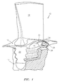
- FIG. 1 there is illustrated a turbine blade 10 assembled into a break away section of a turbine rotor 12.
- the turbine blade 10 has an airfoil portion 14, an integrally formed platform 16, and under platform area 18, a fir tree 20 for securing the turbine blade 10 to the rotor 12, a damper positioning nub 22, and an underside area 24 under the platform 16 into which a blade damper 26 and a seal 28 are positioned.
- FIG. 2 shows a close up of the damper 26 and the seal 28 in the area 24 beneath the platform 16 and the top 30 of the rotor 12.
- FIG. 2 shows the seal 28 as it is initially assembled into the engine with respect to the turbine blade 10.
- the seal 28 is provided with a seal retention feature 32.
- Both the seal 28 and the seal retention feature 32 may be formed as a unitary structure and may be formed from a suitable material.
- the material forming the seal 28 and the seal retention feature 32 may be a nickel based alloy such as a WASPALOY® alloy, or a cobalt based alloy.
- FIG. 2 schematically illustrates the seal retention feature 32 prior to it bending up to contact and conform to an underside 34 of the damper 26 and prior to the sealing surface 36 of the seal 28 seating itself against the underside 24 of the platform 16.
- FIG. 3 is a sectional view of the seal 28 showing the seal 28 and the damper 26 as they would be positioned with the aid of one or more adherents, such as glue and beeswax, at engine assembly.
- the seal retention feature 32 is unbent and fed through a hole 38 in the damper 26.
- the underside 40 of the sealing surface 36 of the seal 28 is glued to the damper 26.
- the damper 26 and the seal 28 are glued to the underside area 24 of the platform 16, aft of the damper positioning nub 22 and above the top 30 of the rotor 12.
- FIG. 4 shows the damper 26 and the seal 28 after the seal 28 has assumed a sealing position after the engine has been spun up to minimum idle. At minimum idle, the rotor 12 is rotating at a rotational rate. The rotational rate will vary from engine to engine. As shown in FIG. 4 , the damper 26 and the sealing surface 36 of the seal 28 are pushed against the underside 24 of the platform 16. As can be seen from this figure, the seal retention feature 32 has bent itself around the top 42 of the hole 38 in the damper 26 and conformed to and positioned itself in contact with the underside 34 of the damper 26.
- FIG. 5 shows the components after green run of the engine when all the adherents, such as glue, have been burnt away.
- the damper 26 has fallen away from the underside 24 of the platform 16 and is resting on the top 30 of the rotor 12.
- the damper 26 typically moves forward such that it can touch the damper positioning nub 22.
- the damper 26 is capable of resting anywhere between the nub 22 and the airfoil buttress 46. Since the adherent has melted, the seal 28 has a loose fit with the damper 26; however, the seal 28 can not fall out because the seal retention feature 32 has been bent by the rotation of the engine.
- the seal 28 can fall away from the bottom surface or underside 34 of the damper 26, but is prevented from falling further because of the sealing portion 36 of the seal 28. It should be noted that the seal 28 is pinned from going forward and aft by the forward and aft vertical surfaces 48 and 50 of the downwardly extending leg 52 of the damper 26.
- the seal retention feature will begin to bend up prior to the rotation rate of the rotor at minimum idle.
- the seal retention feature 32 begins to bend up at 50% to 80% of the rotational rate of the rotor 12 at minimum idle. Further, the seal retention feature 32 begins to bend up at a temperature less than the temperature which is encountered at minimum idle.
- the seal and the seal retention feature will function as described hereinabove.
- the seal retention feature 32 and the weight and length of the seal 28 creates a large enough moment arm and mass such that when the engine is brought up to minimum idle for the first time during green run, the seal 28 will properly seat itself against the under platform of the blade, thereby assuring proper sealing and bending of the seal retention feature 32 into its final assembled position underneath the damper 26.
- the final position of the seal retention feature 32 keeps the seal 28 from vibrating because it is fully supported by the damper and keeps the seal 28 from misalignment and falling out when the engine is turned off.
- the seal 28 with the seal retention feature 32 described herein eliminates small repetitive motion ergonomic issues, allows the seal to properly be seated, avoids tool marking issues, and keeps the seal from misalignment and liberation after green run when assembly glue has been burnt away.
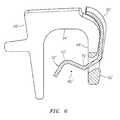
- a seal 30' with a seal retention feature 32' which can be used to create an effective seal between the underside of a platform and a damper.
- the seal 30' is of such weight and length that the center of gravity 60' is located forward of the forward surface 48' of the downwardly extending leg 52' of the damper 26' and beneath the underside 34' of the damper 26'.
- the seal retention feature 32' may be made up of a plurality of angular sections creating a valley 70' and a peak 72'
Landscapes
- Engineering & Computer Science (AREA)
- Mechanical Engineering (AREA)
- General Engineering & Computer Science (AREA)
- Turbine Rotor Nozzle Sealing (AREA)
Abstract
Description
- The present disclosure relates to a seal for a turbine engine component, such as a turbine blade.
- Current turbine blade technology involves creating dampers which do not significantly change their shape when a turbine engine is brought up to speed. The seals associated with the dampers are manually trapped into position as the engine is being assembled.
- There are some disadvantages associated with the current blade seal technology. For example, special tooling is required if it is necessary to bend the seal such that it wraps around another part in order to keep itself in position. This special tooling could leave tool marks on the part. Any such tool marks potentially create high areas of stress that could cause the part to fail while the engine is running. Also, assembling the parts in this manner could prohibit the seal from finding its proper position and thereby compromise the sealing function. Still another issue has to do with the relatively small size of these parts. Repetitive handling and working of the parts could lead to ergonomic issues.
- In prior configurations, the seal for the turbine blade was designed such that it leaned against the blade aft buttress in order to keep it in place. However, the center of gravity of this position caused high cycle fatigue issues and a tab associated with the seal either stayed where it was designed, fold up under the damper, or vibrate itself so much that it would break off and liberate itself into the gas path.
- In accordance with the instant disclosure, there is provided a system broadly comprising: a turbine engine component having an airfoil portion, a platform, and means for joining said turbine engine component to a rotor; a damper located in an area beneath the platform; a seal having a sealing surface which seats against an underside of said platform; said seal having a seal retention feature which bends into contact with an underside of said damper; and said seal with said seal retention feature having a center of gravity which allows said seal retention feature to bend up as result of rotational movement of said rotor.
- Further in accordance with the instant disclosure there is provided a method for creating a seal between a platform portion of a turbine engine component and a damper, said method comprising the steps of: providing a damper having a downwardly extending leg and a hole in said leg; providing a seal having a seal retention feature; positioning said seal against a face of said damper and passing said seal retention feature through said hole; and bending said seal retention feature so that said seal retention feature positions itself in contact with an underside of said damper, said bending step comprising rotating a rotor to which said turbine engine component is attached at a speed which causes said seal retention to bend and move into said contact with said underside of said damper.
- Other details of the engine assembled seal are set forth in the following detailed description and the accompanying drawings, wherein like reference numerals depict like elements.
-
-
FIG. 1 is a schematic representation of a turbine blade assembled to a turbine rotor; -
FIG. 2 is a schematic representation of a damper and seal located in an area beneath a turbine blade platform; -
FIG. 3 is a sectional view of a damper having a seal as positioned at engine assembly; -
FIG. 4 is a sectional view of the damper and seal assembly after the engine has been spun up to minimum idle; -
FIG. 5 is a sectional view of the damper and seal assembly after green run; and -
FIG. 6 illustrates an alternative embodiment of a seal having a seal retention feature. - Referring now to
FIG. 1 , there is illustrated aturbine blade 10 assembled into a break away section of aturbine rotor 12. Theturbine blade 10 has anairfoil portion 14, an integrally formedplatform 16, and underplatform area 18, afir tree 20 for securing theturbine blade 10 to therotor 12, adamper positioning nub 22, and anunderside area 24 under theplatform 16 into which ablade damper 26 and aseal 28 are positioned. - Referring now to
FIG. 2 , there is shown a close up of thedamper 26 and theseal 28 in thearea 24 beneath theplatform 16 and thetop 30 of therotor 12.FIG. 2 shows theseal 28 as it is initially assembled into the engine with respect to theturbine blade 10. Theseal 28 is provided with aseal retention feature 32. Both theseal 28 and theseal retention feature 32 may be formed as a unitary structure and may be formed from a suitable material. The material forming theseal 28 and theseal retention feature 32 may be a nickel based alloy such as a WASPALOY® alloy, or a cobalt based alloy.FIG. 2 schematically illustrates theseal retention feature 32 prior to it bending up to contact and conform to anunderside 34 of thedamper 26 and prior to the sealingsurface 36 of theseal 28 seating itself against theunderside 24 of theplatform 16. -
FIG. 3 is a sectional view of theseal 28 showing theseal 28 and thedamper 26 as they would be positioned with the aid of one or more adherents, such as glue and beeswax, at engine assembly. As shown inFIG. 3 , theseal retention feature 32 is unbent and fed through ahole 38 in thedamper 26. Theunderside 40 of the sealingsurface 36 of theseal 28 is glued to thedamper 26. Further, thedamper 26 and theseal 28 are glued to theunderside area 24 of theplatform 16, aft of thedamper positioning nub 22 and above thetop 30 of therotor 12. -
FIG. 4 shows thedamper 26 and theseal 28 after theseal 28 has assumed a sealing position after the engine has been spun up to minimum idle. At minimum idle, therotor 12 is rotating at a rotational rate. The rotational rate will vary from engine to engine. As shown inFIG. 4 , thedamper 26 and thesealing surface 36 of theseal 28 are pushed against theunderside 24 of theplatform 16. As can be seen from this figure, theseal retention feature 32 has bent itself around thetop 42 of thehole 38 in thedamper 26 and conformed to and positioned itself in contact with theunderside 34 of thedamper 26. -
FIG. 5 shows the components after green run of the engine when all the adherents, such as glue, have been burnt away. Thedamper 26 has fallen away from theunderside 24 of theplatform 16 and is resting on thetop 30 of therotor 12. Thedamper 26 typically moves forward such that it can touch thedamper positioning nub 22. Thedamper 26 is capable of resting anywhere between thenub 22 and theairfoil buttress 46. Since the adherent has melted, theseal 28 has a loose fit with thedamper 26; however, theseal 28 can not fall out because theseal retention feature 32 has been bent by the rotation of the engine. Theseal 28 can fall away from the bottom surface orunderside 34 of thedamper 26, but is prevented from falling further because of the sealingportion 36 of theseal 28. It should be noted that theseal 28 is pinned from going forward and aft by the forward and aftvertical surfaces leg 52 of thedamper 26. - Bending of the seal retention feature 32 into the position shown in
FIG. 4 is brought about by providing aseal 28 which has a center of gravity 60 (seeFig. 3 ) which is located beneath theunderside 34 of thedamper 26 and forward of the forwardvertical surface 48 of the downwardly extendingleg 52 of thedamper 26. Naturally, theseal 28 has a length and a weight which allows the center ofgravity 60 to be located in the aforesaid position. The location of the center of gravity in the aforesaid position helps create a longer moment arm. As a result, rotational movement of therotor 12, caused by rotation of the engine, causes theseal retention feature 32 to bend up into the position shown inFIG. 4 prior to the onset of vibratory conditions prior to minimum idle. It has been found that the seal retention feature will begin to bend up prior to the rotation rate of the rotor at minimum idle. In a particularly useful mode of operation, theseal retention feature 32 begins to bend up at 50% to 80% of the rotational rate of therotor 12 at minimum idle. Further, theseal retention feature 32 begins to bend up at a temperature less than the temperature which is encountered at minimum idle. Of course, it should be appreciated that different engines will have different rotational rates and temperatures at minimum idle. However, regardless of the engine, the seal and the seal retention feature will function as described hereinabove. The seal retention feature 32 and the weight and length of theseal 28 creates a large enough moment arm and mass such that when the engine is brought up to minimum idle for the first time during green run, theseal 28 will properly seat itself against the under platform of the blade, thereby assuring proper sealing and bending of the seal retention feature 32 into its final assembled position underneath thedamper 26. The final position of theseal retention feature 32 keeps theseal 28 from vibrating because it is fully supported by the damper and keeps theseal 28 from misalignment and falling out when the engine is turned off. - The
seal 28 with theseal retention feature 32 described herein eliminates small repetitive motion ergonomic issues, allows the seal to properly be seated, avoids tool marking issues, and keeps the seal from misalignment and liberation after green run when assembly glue has been burnt away. - Referring now to
FIG. 6 , there is shown a seal 30' with a seal retention feature 32' which can be used to create an effective seal between the underside of a platform and a damper. The seal 30' is of such weight and length that the center of gravity 60' is located forward of the forward surface 48' of the downwardly extending leg 52' of the damper 26' and beneath the underside 34' of the damper 26'. The seal retention feature 32' may be made up of a plurality of angular sections creating a valley 70' and a peak 72' - There has been provided in accordance with the instant disclosure an engine assembled seal. While the seal has been described in the context of specific embodiments thereof, other unforeseen alternatives, modifications, and variations may become apparent to those skilled in the art having read the foregoing description. Accordingly, it is intended to embrace those alternatives, modifications, and variations as fall within the broad scope of the appended claims.
Claims (15)
- A system comprising:a turbine engine component (10) having an airfoil portion (14), a platform (16), and means (20) for joining said turbine engine component (10) to a rotor (12);a damper (26) located in an area beneath the platform (16);a seal (28) having a sealing surface (36) which seats against an underside (24) of said platform (16);said seal (28) having a seal retention feature (32) which bends into contact with an underside (34) of said damper (26); andsaid seal (28) with said seal retention feature (32) having a center of gravity which allows said seal retention feature (32) to bend up as result of rotational movement of said rotor (12).
- The system according to claim 1, wherein said damper (26) has a hole (38) and said seal retention feature (32) passes through said hole (38).
- The system according to claim 2, wherein said seal retention feature (32) bends around a top (42) of the hole (38) as said seal retention feature (32) bends up and contacts the underside (34) of the damper (26).
- The system according to any preceding claim, wherein said damper (26) has a downwardly extending leg (52) with a hole (38) through which said seal retention feature (32) passes and said center of gravity being located forward of a front face (48) of said downwardly extending leg (52).
- The system according to claim 4, wherein said center of gravity is located beneath said platform (16).
- The system according to any preceding claim, wherein said seal (28) having said seal retention feature (32) is formed from one of a nickel based alloy and a cobalt based alloy.
- The system according to any preceding claim, wherein said seal retention feature (32) bends up at a rotor rotational rate less than a rotational rate for said rotor (12) at minimum idle, for example at a rotor rotational rate which is from 50% to 80% of a rotational rate for said rotor (12) at minimum idle.
- The system according to claim 7, wherein said seal retention feature (32) bends up at a temperature less than a temperature at said minimum idle.
- The system according to any preceding claim, wherein said seal (28) has a length and a weight sufficient to create a moment as said rotor (12) rotates which allows said seal retention feature (32) to bend up.
- A method for creating a seal between a platform portion (16) of a turbine engine component (10) and a damper (26), said method comprising the steps of:providing a damper (26) having a downwardly extending leg (52) and a hole (38) in said leg (52);providing a seal (28) having a seal retention feature (32);positioning said seal (28) against a face of said damper (26) and passing said seal retention feature (32) through said hole (38); andbending said seal retention feature (32) so that said seal retention feature (32) positions itself in contact with an underside (34) of said damper (26), said bending step comprising rotating a rotor (12) to which said turbine engine component (10) is attached at a speed which causes said seal retention feature (32) to bend and move into said contact with said underside (34) of said damper (26).
- The method according to claim 10, wherein said seal providing step comprises providing a seal (30) having a center of gravity which is located forward of said downwardly extending leg (52).
- The method according to claim 10 or 11, wherein said rotating step comprises rotating said rotor (12) at a rotational speed less than a rotational speed of said rotor (12) at minimum idle.
- The method according to claim 10 or 11, wherein said rotating step comprises rotating said rotor (12) at a rotational speed which is 50% to 80% of a rotational speed of said rotor (12) at minimum idle.
- The method according to any of claims 10 to 13, further comprising adhering an underside (40) of said seal (28) to the damper (26) and adhering both the damper (26) and said seal (28) to an underside (24) of the platform (16).
- The method according to claim 14, wherein said step of adhering said seal (28) to the damper (26) comprises gluing said seal (28) to said damper (26) and said step of adhering both the damper (26) and the seal (28) to the underside (24) of the platform (16) comprises gluing said damper (26) and said seal (28) to said underside (24) of the platform (16).
Applications Claiming Priority (1)
| Application Number | Priority Date | Filing Date | Title |
|---|---|---|---|
| US12/764,212 US8672626B2 (en) | 2010-04-21 | 2010-04-21 | Engine assembled seal |
Publications (3)
| Publication Number | Publication Date |
|---|---|
| EP2381067A2 true EP2381067A2 (en) | 2011-10-26 |
| EP2381067A3 EP2381067A3 (en) | 2014-06-18 |
| EP2381067B1 EP2381067B1 (en) | 2018-11-07 |
Family
ID=44019492
Family Applications (1)
| Application Number | Title | Priority Date | Filing Date |
|---|---|---|---|
| EP11163022.4A Active EP2381067B1 (en) | 2010-04-21 | 2011-04-19 | Seal and damper arrangement of a turbomachine and method for creating a seal |
Country Status (2)
| Country | Link |
|---|---|
| US (1) | US8672626B2 (en) |
| EP (1) | EP2381067B1 (en) |
Cited By (2)
| Publication number | Priority date | Publication date | Assignee | Title |
|---|---|---|---|---|
| EP2455587B1 (en) * | 2010-11-17 | 2019-01-23 | MTU Aero Engines GmbH | Rotor for a turbomachine, corrresponding turbomachine and method for manufacturing, repairing or upgrading |
| US10851661B2 (en) | 2017-08-01 | 2020-12-01 | General Electric Company | Sealing system for a rotary machine and method of assembling same |
Families Citing this family (22)
| Publication number | Priority date | Publication date | Assignee | Title |
|---|---|---|---|---|
| US8672626B2 (en) * | 2010-04-21 | 2014-03-18 | United Technologies Corporation | Engine assembled seal |
| US9273566B2 (en) | 2012-06-22 | 2016-03-01 | United Technologies Corporation | Turbine engine variable area vane |
| US9103222B2 (en) | 2012-06-22 | 2015-08-11 | United Technologies Corporation | Turbine engine variable area vane with feather seal |
| US10215048B2 (en) | 2013-01-21 | 2019-02-26 | United Technologies Corporation | Variable area vane arrangement for a turbine engine |
| US10012085B2 (en) * | 2013-03-13 | 2018-07-03 | United Technologies Corporation | Turbine blade and damper retention |
| US10641109B2 (en) | 2013-03-13 | 2020-05-05 | United Technologies Corporation | Mass offset for damping performance |
| EP2806106A1 (en) | 2013-05-23 | 2014-11-26 | MTU Aero Engines GmbH | Blade of a turbomachine having an impulse body |
| US9765625B2 (en) * | 2013-05-23 | 2017-09-19 | MTU Aero Engines AG | Turbomachine blade |
| US9856737B2 (en) * | 2014-03-27 | 2018-01-02 | United Technologies Corporation | Blades and blade dampers for gas turbine engines |
| US9995162B2 (en) * | 2014-10-20 | 2018-06-12 | United Technologies Corporation | Seal and clip-on damper system and device |
| US9863257B2 (en) * | 2015-02-04 | 2018-01-09 | United Technologies Corporation | Additive manufactured inseparable platform damper and seal assembly for a gas turbine engine |
| US9810075B2 (en) | 2015-03-20 | 2017-11-07 | United Technologies Corporation | Faceted turbine blade damper-seal |
| US9920637B2 (en) | 2015-04-07 | 2018-03-20 | United Technologies Corporation | Gas turbine engine damping device |
| US10941671B2 (en) * | 2017-03-23 | 2021-03-09 | General Electric Company | Gas turbine engine component incorporating a seal slot |
| JP7039355B2 (en) * | 2018-03-28 | 2022-03-22 | 三菱重工業株式会社 | Rotating machine |
| US11248475B2 (en) * | 2019-12-10 | 2022-02-15 | General Electric Company | Damper stacks for turbomachine rotor blades |
| US11187089B2 (en) * | 2019-12-10 | 2021-11-30 | General Electric Company | Damper stacks for turbomachine rotor blades |
| JP7756559B2 (en) * | 2021-12-22 | 2025-10-20 | 三菱重工業株式会社 | Rotating Machinery |
| KR102821442B1 (en) * | 2022-11-23 | 2025-06-16 | 두산에너빌리티 주식회사 | Turbine vane platform sealing assembly, turbine vane and gas turbine comprising it |
| KR102868006B1 (en) | 2022-12-09 | 2025-10-01 | 두산에너빌리티 주식회사 | Turbine vane having a seal assembly, turbine and turbomachine comprising the same |
| KR102791366B1 (en) | 2022-12-12 | 2025-04-07 | 두산에너빌리티 주식회사 | Turbine vane platform sealing assembly, turbine vane and gas turbine comprising it |
| US20240271537A1 (en) * | 2023-02-14 | 2024-08-15 | Raytheon Technologies Corporation | Machinable coating for damping |
Family Cites Families (16)
| Publication number | Priority date | Publication date | Assignee | Title |
|---|---|---|---|---|
| FR2527260A1 (en) * | 1982-05-18 | 1983-11-25 | Snecma | RETRACTABLE DAMPING DEVICE FOR AUBES OF A TURBOMACHINE |
| US4872810A (en) | 1988-12-14 | 1989-10-10 | United Technologies Corporation | Turbine rotor retention system |
| US5261790A (en) * | 1992-02-03 | 1993-11-16 | General Electric Company | Retention device for turbine blade damper |
| US5228835A (en) | 1992-11-24 | 1993-07-20 | United Technologies Corporation | Gas turbine blade seal |
| US5460489A (en) * | 1994-04-12 | 1995-10-24 | United Technologies Corporation | Turbine blade damper and seal |
| US5573375A (en) * | 1994-12-14 | 1996-11-12 | United Technologies Corporation | Turbine engine rotor blade platform sealing and vibration damping device |
| US5513955A (en) | 1994-12-14 | 1996-05-07 | United Technologies Corporation | Turbine engine rotor blade platform seal |
| US5827047A (en) * | 1996-06-27 | 1998-10-27 | United Technologies Corporation | Turbine blade damper and seal |
| US5785499A (en) * | 1996-12-24 | 1998-07-28 | United Technologies Corporation | Turbine blade damper and seal |
| US5924699A (en) | 1996-12-24 | 1999-07-20 | United Technologies Corporation | Turbine blade platform seal |
| US6171058B1 (en) | 1999-04-01 | 2001-01-09 | General Electric Company | Self retaining blade damper |
| US6932575B2 (en) | 2003-10-08 | 2005-08-23 | United Technologies Corporation | Blade damper |
| US7121800B2 (en) | 2004-09-13 | 2006-10-17 | United Technologies Corporation | Turbine blade nested seal damper assembly |
| US8011892B2 (en) * | 2007-06-28 | 2011-09-06 | United Technologies Corporation | Turbine blade nested seal and damper assembly |
| US8672626B2 (en) * | 2010-04-21 | 2014-03-18 | United Technologies Corporation | Engine assembled seal |
| US10113434B2 (en) * | 2012-01-31 | 2018-10-30 | United Technologies Corporation | Turbine blade damper seal |
-
2010
- 2010-04-21 US US12/764,212 patent/US8672626B2/en active Active
-
2011
- 2011-04-19 EP EP11163022.4A patent/EP2381067B1/en active Active
Non-Patent Citations (1)
| Title |
|---|
| None |
Cited By (2)
| Publication number | Priority date | Publication date | Assignee | Title |
|---|---|---|---|---|
| EP2455587B1 (en) * | 2010-11-17 | 2019-01-23 | MTU Aero Engines GmbH | Rotor for a turbomachine, corrresponding turbomachine and method for manufacturing, repairing or upgrading |
| US10851661B2 (en) | 2017-08-01 | 2020-12-01 | General Electric Company | Sealing system for a rotary machine and method of assembling same |
Also Published As
| Publication number | Publication date |
|---|---|
| US8672626B2 (en) | 2014-03-18 |
| US20110262274A1 (en) | 2011-10-27 |
| EP2381067A3 (en) | 2014-06-18 |
| EP2381067B1 (en) | 2018-11-07 |
Similar Documents
| Publication | Publication Date | Title |
|---|---|---|
| US8672626B2 (en) | Engine assembled seal | |
| EP3093434B1 (en) | Faceted turbine blade damper-seal | |
| EP2841697B1 (en) | Airfoil including member connected by articulated joint | |
| US20130195665A1 (en) | Turbine blade damper seal | |
| US8267663B2 (en) | Multi-cast turbine airfoils and method for making same | |
| EP2855849B1 (en) | Airfoil cover system | |
| EP1626163A2 (en) | Clip member for a stator assembly | |
| EP2971597B1 (en) | Machined vane arm of a variable vane actuation system | |
| EP2241721A3 (en) | Airfoil with feature against flow separation, corresponding gas turbine engine and operating method | |
| EP1772592A3 (en) | Dust resistant platform blade | |
| EP2841705B1 (en) | Airfoil and corresponding method for processing an airfoil | |
| EP3321472B1 (en) | Gas turbine engine with fan blade | |
| JP2009036192A (en) | Method for protecting airfoils and leading edges of airfoils | |
| EP2149674A3 (en) | Vibration damper. | |
| GB0412775D0 (en) | Method of replacing damaged aerofoil | |
| US20140286756A1 (en) | Device, system and method for preventing leakage in a turbine | |
| JP2007192223A (en) | Rehabilitation of trailing edge and platform of turbine part by laser cladding | |
| US9879545B2 (en) | Manufacture of hollow aerofoil | |
| WO2005074469A3 (en) | Mitigation of unsteady peak fan blade and disc stresses in turbofan engines | |
| US20180016934A1 (en) | Method for release of fan blisk airfoil | |
| EP1801356A3 (en) | Combustor turbine interface | |
| EP3139005A1 (en) | Gas turbine fan fairing platform and method of fairing a root leading edge of a fan blade of a gas turbine engine | |
| EP1808263A3 (en) | Chordwidth restoration of a trailing edge of a turbine airfoil by laser clad | |
| EP3244020A2 (en) | Gas turbine engine having a vane assembly | |
| EP1621728A3 (en) | Hybrid turbine blade and related method |
Legal Events
| Date | Code | Title | Description |
|---|---|---|---|
| AK | Designated contracting states |
Kind code of ref document: A2 Designated state(s): AL AT BE BG CH CY CZ DE DK EE ES FI FR GB GR HR HU IE IS IT LI LT LU LV MC MK MT NL NO PL PT RO RS SE SI SK SM TR |
|
| AX | Request for extension of the european patent |
Extension state: BA ME |
|
| PUAI | Public reference made under article 153(3) epc to a published international application that has entered the european phase |
Free format text: ORIGINAL CODE: 0009012 |
|
| PUAL | Search report despatched |
Free format text: ORIGINAL CODE: 0009013 |
|
| AK | Designated contracting states |
Kind code of ref document: A3 Designated state(s): AL AT BE BG CH CY CZ DE DK EE ES FI FR GB GR HR HU IE IS IT LI LT LU LV MC MK MT NL NO PL PT RO RS SE SI SK SM TR |
|
| AX | Request for extension of the european patent |
Extension state: BA ME |
|
| RIC1 | Information provided on ipc code assigned before grant |
Ipc: F01D 11/00 20060101ALI20140514BHEP Ipc: F01D 5/26 20060101AFI20140514BHEP |
|
| 17P | Request for examination filed |
Effective date: 20141211 |
|
| RBV | Designated contracting states (corrected) |
Designated state(s): AL AT BE BG CH CY CZ DE DK EE ES FI FR GB GR HR HU IE IS IT LI LT LU LV MC MK MT NL NO PL PT RO RS SE SI SK SM TR |
|
| RAP1 | Party data changed (applicant data changed or rights of an application transferred) |
Owner name: UNITED TECHNOLOGIES CORPORATION |
|
| GRAP | Despatch of communication of intention to grant a patent |
Free format text: ORIGINAL CODE: EPIDOSNIGR1 |
|
| STAA | Information on the status of an ep patent application or granted ep patent |
Free format text: STATUS: GRANT OF PATENT IS INTENDED |
|
| INTG | Intention to grant announced |
Effective date: 20180517 |
|
| GRAS | Grant fee paid |
Free format text: ORIGINAL CODE: EPIDOSNIGR3 |
|
| GRAA | (expected) grant |
Free format text: ORIGINAL CODE: 0009210 |
|
| STAA | Information on the status of an ep patent application or granted ep patent |
Free format text: STATUS: THE PATENT HAS BEEN GRANTED |
|
| AK | Designated contracting states |
Kind code of ref document: B1 Designated state(s): AL AT BE BG CH CY CZ DE DK EE ES FI FR GB GR HR HU IE IS IT LI LT LU LV MC MK MT NL NO PL PT RO RS SE SI SK SM TR |
|
| REG | Reference to a national code |
Ref country code: GB Ref legal event code: FG4D |
|
| REG | Reference to a national code |
Ref country code: CH Ref legal event code: EP Ref country code: AT Ref legal event code: REF Ref document number: 1062290 Country of ref document: AT Kind code of ref document: T Effective date: 20181115 |
|
| REG | Reference to a national code |
Ref country code: IE Ref legal event code: FG4D |
|
| REG | Reference to a national code |
Ref country code: DE Ref legal event code: R096 Ref document number: 602011053569 Country of ref document: DE |
|
| REG | Reference to a national code |
Ref country code: NL Ref legal event code: MP Effective date: 20181107 |
|
| REG | Reference to a national code |
Ref country code: LT Ref legal event code: MG4D |
|
| REG | Reference to a national code |
Ref country code: AT Ref legal event code: MK05 Ref document number: 1062290 Country of ref document: AT Kind code of ref document: T Effective date: 20181107 |
|
| PG25 | Lapsed in a contracting state [announced via postgrant information from national office to epo] |
Ref country code: AT Free format text: LAPSE BECAUSE OF FAILURE TO SUBMIT A TRANSLATION OF THE DESCRIPTION OR TO PAY THE FEE WITHIN THE PRESCRIBED TIME-LIMIT Effective date: 20181107 Ref country code: HR Free format text: LAPSE BECAUSE OF FAILURE TO SUBMIT A TRANSLATION OF THE DESCRIPTION OR TO PAY THE FEE WITHIN THE PRESCRIBED TIME-LIMIT Effective date: 20181107 Ref country code: LV Free format text: LAPSE BECAUSE OF FAILURE TO SUBMIT A TRANSLATION OF THE DESCRIPTION OR TO PAY THE FEE WITHIN THE PRESCRIBED TIME-LIMIT Effective date: 20181107 Ref country code: NO Free format text: LAPSE BECAUSE OF FAILURE TO SUBMIT A TRANSLATION OF THE DESCRIPTION OR TO PAY THE FEE WITHIN THE PRESCRIBED TIME-LIMIT Effective date: 20190207 Ref country code: FI Free format text: LAPSE BECAUSE OF FAILURE TO SUBMIT A TRANSLATION OF THE DESCRIPTION OR TO PAY THE FEE WITHIN THE PRESCRIBED TIME-LIMIT Effective date: 20181107 Ref country code: IS Free format text: LAPSE BECAUSE OF FAILURE TO SUBMIT A TRANSLATION OF THE DESCRIPTION OR TO PAY THE FEE WITHIN THE PRESCRIBED TIME-LIMIT Effective date: 20190307 Ref country code: ES Free format text: LAPSE BECAUSE OF FAILURE TO SUBMIT A TRANSLATION OF THE DESCRIPTION OR TO PAY THE FEE WITHIN THE PRESCRIBED TIME-LIMIT Effective date: 20181107 Ref country code: LT Free format text: LAPSE BECAUSE OF FAILURE TO SUBMIT A TRANSLATION OF THE DESCRIPTION OR TO PAY THE FEE WITHIN THE PRESCRIBED TIME-LIMIT Effective date: 20181107 Ref country code: BG Free format text: LAPSE BECAUSE OF FAILURE TO SUBMIT A TRANSLATION OF THE DESCRIPTION OR TO PAY THE FEE WITHIN THE PRESCRIBED TIME-LIMIT Effective date: 20190207 |
|
| PG25 | Lapsed in a contracting state [announced via postgrant information from national office to epo] |
Ref country code: GR Free format text: LAPSE BECAUSE OF FAILURE TO SUBMIT A TRANSLATION OF THE DESCRIPTION OR TO PAY THE FEE WITHIN THE PRESCRIBED TIME-LIMIT Effective date: 20190208 Ref country code: NL Free format text: LAPSE BECAUSE OF FAILURE TO SUBMIT A TRANSLATION OF THE DESCRIPTION OR TO PAY THE FEE WITHIN THE PRESCRIBED TIME-LIMIT Effective date: 20181107 Ref country code: AL Free format text: LAPSE BECAUSE OF FAILURE TO SUBMIT A TRANSLATION OF THE DESCRIPTION OR TO PAY THE FEE WITHIN THE PRESCRIBED TIME-LIMIT Effective date: 20181107 Ref country code: PT Free format text: LAPSE BECAUSE OF FAILURE TO SUBMIT A TRANSLATION OF THE DESCRIPTION OR TO PAY THE FEE WITHIN THE PRESCRIBED TIME-LIMIT Effective date: 20190307 Ref country code: SE Free format text: LAPSE BECAUSE OF FAILURE TO SUBMIT A TRANSLATION OF THE DESCRIPTION OR TO PAY THE FEE WITHIN THE PRESCRIBED TIME-LIMIT Effective date: 20181107 Ref country code: RS Free format text: LAPSE BECAUSE OF FAILURE TO SUBMIT A TRANSLATION OF THE DESCRIPTION OR TO PAY THE FEE WITHIN THE PRESCRIBED TIME-LIMIT Effective date: 20181107 |
|
| PG25 | Lapsed in a contracting state [announced via postgrant information from national office to epo] |
Ref country code: DK Free format text: LAPSE BECAUSE OF FAILURE TO SUBMIT A TRANSLATION OF THE DESCRIPTION OR TO PAY THE FEE WITHIN THE PRESCRIBED TIME-LIMIT Effective date: 20181107 Ref country code: PL Free format text: LAPSE BECAUSE OF FAILURE TO SUBMIT A TRANSLATION OF THE DESCRIPTION OR TO PAY THE FEE WITHIN THE PRESCRIBED TIME-LIMIT Effective date: 20181107 Ref country code: CZ Free format text: LAPSE BECAUSE OF FAILURE TO SUBMIT A TRANSLATION OF THE DESCRIPTION OR TO PAY THE FEE WITHIN THE PRESCRIBED TIME-LIMIT Effective date: 20181107 Ref country code: IT Free format text: LAPSE BECAUSE OF FAILURE TO SUBMIT A TRANSLATION OF THE DESCRIPTION OR TO PAY THE FEE WITHIN THE PRESCRIBED TIME-LIMIT Effective date: 20181107 |
|
| REG | Reference to a national code |
Ref country code: DE Ref legal event code: R097 Ref document number: 602011053569 Country of ref document: DE |
|
| PG25 | Lapsed in a contracting state [announced via postgrant information from national office to epo] |
Ref country code: RO Free format text: LAPSE BECAUSE OF FAILURE TO SUBMIT A TRANSLATION OF THE DESCRIPTION OR TO PAY THE FEE WITHIN THE PRESCRIBED TIME-LIMIT Effective date: 20181107 Ref country code: SM Free format text: LAPSE BECAUSE OF FAILURE TO SUBMIT A TRANSLATION OF THE DESCRIPTION OR TO PAY THE FEE WITHIN THE PRESCRIBED TIME-LIMIT Effective date: 20181107 Ref country code: EE Free format text: LAPSE BECAUSE OF FAILURE TO SUBMIT A TRANSLATION OF THE DESCRIPTION OR TO PAY THE FEE WITHIN THE PRESCRIBED TIME-LIMIT Effective date: 20181107 Ref country code: SK Free format text: LAPSE BECAUSE OF FAILURE TO SUBMIT A TRANSLATION OF THE DESCRIPTION OR TO PAY THE FEE WITHIN THE PRESCRIBED TIME-LIMIT Effective date: 20181107 |
|
| PLBE | No opposition filed within time limit |
Free format text: ORIGINAL CODE: 0009261 |
|
| STAA | Information on the status of an ep patent application or granted ep patent |
Free format text: STATUS: NO OPPOSITION FILED WITHIN TIME LIMIT |
|
| 26N | No opposition filed |
Effective date: 20190808 |
|
| PG25 | Lapsed in a contracting state [announced via postgrant information from national office to epo] |
Ref country code: SI Free format text: LAPSE BECAUSE OF FAILURE TO SUBMIT A TRANSLATION OF THE DESCRIPTION OR TO PAY THE FEE WITHIN THE PRESCRIBED TIME-LIMIT Effective date: 20181107 |
|
| REG | Reference to a national code |
Ref country code: CH Ref legal event code: PL |
|
| REG | Reference to a national code |
Ref country code: BE Ref legal event code: MM Effective date: 20190430 |
|
| PG25 | Lapsed in a contracting state [announced via postgrant information from national office to epo] |
Ref country code: MC Free format text: LAPSE BECAUSE OF FAILURE TO SUBMIT A TRANSLATION OF THE DESCRIPTION OR TO PAY THE FEE WITHIN THE PRESCRIBED TIME-LIMIT Effective date: 20181107 Ref country code: LU Free format text: LAPSE BECAUSE OF NON-PAYMENT OF DUE FEES Effective date: 20190419 |
|
| PG25 | Lapsed in a contracting state [announced via postgrant information from national office to epo] |
Ref country code: CH Free format text: LAPSE BECAUSE OF NON-PAYMENT OF DUE FEES Effective date: 20190430 Ref country code: LI Free format text: LAPSE BECAUSE OF NON-PAYMENT OF DUE FEES Effective date: 20190430 |
|
| PG25 | Lapsed in a contracting state [announced via postgrant information from national office to epo] |
Ref country code: BE Free format text: LAPSE BECAUSE OF NON-PAYMENT OF DUE FEES Effective date: 20190430 |
|
| PG25 | Lapsed in a contracting state [announced via postgrant information from national office to epo] |
Ref country code: TR Free format text: LAPSE BECAUSE OF FAILURE TO SUBMIT A TRANSLATION OF THE DESCRIPTION OR TO PAY THE FEE WITHIN THE PRESCRIBED TIME-LIMIT Effective date: 20181107 |
|
| PG25 | Lapsed in a contracting state [announced via postgrant information from national office to epo] |
Ref country code: IE Free format text: LAPSE BECAUSE OF NON-PAYMENT OF DUE FEES Effective date: 20190419 |
|
| PG25 | Lapsed in a contracting state [announced via postgrant information from national office to epo] |
Ref country code: CY Free format text: LAPSE BECAUSE OF FAILURE TO SUBMIT A TRANSLATION OF THE DESCRIPTION OR TO PAY THE FEE WITHIN THE PRESCRIBED TIME-LIMIT Effective date: 20181107 |
|
| PG25 | Lapsed in a contracting state [announced via postgrant information from national office to epo] |
Ref country code: HU Free format text: LAPSE BECAUSE OF FAILURE TO SUBMIT A TRANSLATION OF THE DESCRIPTION OR TO PAY THE FEE WITHIN THE PRESCRIBED TIME-LIMIT; INVALID AB INITIO Effective date: 20110419 Ref country code: MT Free format text: LAPSE BECAUSE OF FAILURE TO SUBMIT A TRANSLATION OF THE DESCRIPTION OR TO PAY THE FEE WITHIN THE PRESCRIBED TIME-LIMIT Effective date: 20181107 |
|
| PG25 | Lapsed in a contracting state [announced via postgrant information from national office to epo] |
Ref country code: MK Free format text: LAPSE BECAUSE OF FAILURE TO SUBMIT A TRANSLATION OF THE DESCRIPTION OR TO PAY THE FEE WITHIN THE PRESCRIBED TIME-LIMIT Effective date: 20181107 |
|
| REG | Reference to a national code |
Ref country code: DE Ref legal event code: R081 Ref document number: 602011053569 Country of ref document: DE Owner name: RAYTHEON TECHNOLOGIES CORPORATION (N.D.GES.D.S, US Free format text: FORMER OWNER: UNITED TECHNOLOGIES CORPORATION, FARMINGTON, CONN., US Ref country code: DE Ref legal event code: R081 Ref document number: 602011053569 Country of ref document: DE Owner name: RTX CORPORATION (N.D.GES.D. STAATES DELAWARE),, US Free format text: FORMER OWNER: UNITED TECHNOLOGIES CORPORATION, FARMINGTON, CONN., US |
|
| P01 | Opt-out of the competence of the unified patent court (upc) registered |
Effective date: 20230519 |
|
| PGFP | Annual fee paid to national office [announced via postgrant information from national office to epo] |
Ref country code: DE Payment date: 20250319 Year of fee payment: 15 |
|
| REG | Reference to a national code |
Ref country code: DE Ref legal event code: R081 Ref document number: 602011053569 Country of ref document: DE Owner name: RTX CORPORATION (N.D.GES.D. STAATES DELAWARE),, US Free format text: FORMER OWNER: RAYTHEON TECHNOLOGIES CORPORATION (N.D.GES.D.STAATES DELAWARE), ARLINGTON, VA, US |
|
| PGFP | Annual fee paid to national office [announced via postgrant information from national office to epo] |
Ref country code: GB Payment date: 20260319 Year of fee payment: 16 |
|
| PGFP | Annual fee paid to national office [announced via postgrant information from national office to epo] |
Ref country code: FR Payment date: 20260319 Year of fee payment: 16 |