EP2380513A1 - Bone stabilization device - Google Patents
Bone stabilization device Download PDFInfo
- Publication number
- EP2380513A1 EP2380513A1 EP11174731A EP11174731A EP2380513A1 EP 2380513 A1 EP2380513 A1 EP 2380513A1 EP 11174731 A EP11174731 A EP 11174731A EP 11174731 A EP11174731 A EP 11174731A EP 2380513 A1 EP2380513 A1 EP 2380513A1
- Authority
- EP
- European Patent Office
- Prior art keywords
- receiving part
- bone
- rod
- recess
- section
- Prior art date
- Legal status (The legal status is an assumption and is not a legal conclusion. Google has not performed a legal analysis and makes no representation as to the accuracy of the status listed.)
- Granted
Links
- 210000000988 bone and bone Anatomy 0.000 title claims abstract description 92
- 230000006641 stabilisation Effects 0.000 title claims abstract description 19
- 238000011105 stabilization Methods 0.000 title claims abstract description 19
- 238000004873 anchoring Methods 0.000 claims abstract description 55
- 239000007943 implant Substances 0.000 claims abstract description 25
- 238000003780 insertion Methods 0.000 claims abstract description 11
- 230000037431 insertion Effects 0.000 claims abstract description 11
- 238000005452 bending Methods 0.000 description 4
- 239000000560 biocompatible material Substances 0.000 description 2
- 230000006835 compression Effects 0.000 description 2
- 238000007906 compression Methods 0.000 description 2
- 230000007423 decrease Effects 0.000 description 2
- 230000003247 decreasing effect Effects 0.000 description 2
- 230000000694 effects Effects 0.000 description 2
- 238000004880 explosion Methods 0.000 description 2
- 238000012986 modification Methods 0.000 description 2
- 230000004048 modification Effects 0.000 description 2
- 210000000115 thoracic cavity Anatomy 0.000 description 2
- 229910001069 Ti alloy Inorganic materials 0.000 description 1
- RTAQQCXQSZGOHL-UHFFFAOYSA-N Titanium Chemical compound [Ti] RTAQQCXQSZGOHL-UHFFFAOYSA-N 0.000 description 1
- 210000003484 anatomy Anatomy 0.000 description 1
- 238000002513 implantation Methods 0.000 description 1
- 208000014674 injury Diseases 0.000 description 1
- 210000004705 lumbosacral region Anatomy 0.000 description 1
- 239000000463 material Substances 0.000 description 1
- 229910052751 metal Inorganic materials 0.000 description 1
- 239000002184 metal Substances 0.000 description 1
- 150000002739 metals Chemical class 0.000 description 1
- 238000000034 method Methods 0.000 description 1
- 238000001356 surgical procedure Methods 0.000 description 1
- 239000010936 titanium Substances 0.000 description 1
- 229910052719 titanium Inorganic materials 0.000 description 1
- 230000008733 trauma Effects 0.000 description 1
Images






Classifications
-
- A—HUMAN NECESSITIES
- A61—MEDICAL OR VETERINARY SCIENCE; HYGIENE
- A61B—DIAGNOSIS; SURGERY; IDENTIFICATION
- A61B17/00—Surgical instruments, devices or methods
- A61B17/56—Surgical instruments or methods for treatment of bones or joints; Devices specially adapted therefor
- A61B17/58—Surgical instruments or methods for treatment of bones or joints; Devices specially adapted therefor for osteosynthesis, e.g. bone plates, screws or setting implements
- A61B17/68—Internal fixation devices, including fasteners and spinal fixators, even if a part thereof projects from the skin
- A61B17/70—Spinal positioners or stabilisers, e.g. stabilisers comprising fluid filler in an implant
- A61B17/7001—Screws or hooks combined with longitudinal elements which do not contact vertebrae
- A61B17/7032—Screws or hooks with U-shaped head or back through which longitudinal rods pass
-
- A—HUMAN NECESSITIES
- A61—MEDICAL OR VETERINARY SCIENCE; HYGIENE
- A61B—DIAGNOSIS; SURGERY; IDENTIFICATION
- A61B17/00—Surgical instruments, devices or methods
- A61B17/56—Surgical instruments or methods for treatment of bones or joints; Devices specially adapted therefor
- A61B17/58—Surgical instruments or methods for treatment of bones or joints; Devices specially adapted therefor for osteosynthesis, e.g. bone plates, screws or setting implements
- A61B17/68—Internal fixation devices, including fasteners and spinal fixators, even if a part thereof projects from the skin
- A61B17/70—Spinal positioners or stabilisers, e.g. stabilisers comprising fluid filler in an implant
-
- A—HUMAN NECESSITIES
- A61—MEDICAL OR VETERINARY SCIENCE; HYGIENE
- A61B—DIAGNOSIS; SURGERY; IDENTIFICATION
- A61B17/00—Surgical instruments, devices or methods
- A61B17/56—Surgical instruments or methods for treatment of bones or joints; Devices specially adapted therefor
- A61B17/58—Surgical instruments or methods for treatment of bones or joints; Devices specially adapted therefor for osteosynthesis, e.g. bone plates, screws or setting implements
- A61B17/68—Internal fixation devices, including fasteners and spinal fixators, even if a part thereof projects from the skin
- A61B17/70—Spinal positioners or stabilisers, e.g. stabilisers comprising fluid filler in an implant
- A61B17/7001—Screws or hooks combined with longitudinal elements which do not contact vertebrae
- A61B17/7035—Screws or hooks, wherein a rod-clamping part and a bone-anchoring part can pivot relative to each other
- A61B17/7037—Screws or hooks, wherein a rod-clamping part and a bone-anchoring part can pivot relative to each other wherein pivoting is blocked when the rod is clamped
-
- A—HUMAN NECESSITIES
- A61—MEDICAL OR VETERINARY SCIENCE; HYGIENE
- A61B—DIAGNOSIS; SURGERY; IDENTIFICATION
- A61B17/00—Surgical instruments, devices or methods
- A61B17/56—Surgical instruments or methods for treatment of bones or joints; Devices specially adapted therefor
- A61B17/58—Surgical instruments or methods for treatment of bones or joints; Devices specially adapted therefor for osteosynthesis, e.g. bone plates, screws or setting implements
- A61B17/68—Internal fixation devices, including fasteners and spinal fixators, even if a part thereof projects from the skin
- A61B17/82—Internal fixation devices, including fasteners and spinal fixators, even if a part thereof projects from the skin for bone cerclage
-
- A—HUMAN NECESSITIES
- A61—MEDICAL OR VETERINARY SCIENCE; HYGIENE
- A61B—DIAGNOSIS; SURGERY; IDENTIFICATION
- A61B17/00—Surgical instruments, devices or methods
- A61B17/56—Surgical instruments or methods for treatment of bones or joints; Devices specially adapted therefor
- A61B17/58—Surgical instruments or methods for treatment of bones or joints; Devices specially adapted therefor for osteosynthesis, e.g. bone plates, screws or setting implements
- A61B17/68—Internal fixation devices, including fasteners and spinal fixators, even if a part thereof projects from the skin
- A61B17/84—Fasteners therefor or fasteners being internal fixation devices
-
- A—HUMAN NECESSITIES
- A61—MEDICAL OR VETERINARY SCIENCE; HYGIENE
- A61B—DIAGNOSIS; SURGERY; IDENTIFICATION
- A61B17/00—Surgical instruments, devices or methods
- A61B17/56—Surgical instruments or methods for treatment of bones or joints; Devices specially adapted therefor
- A61B17/58—Surgical instruments or methods for treatment of bones or joints; Devices specially adapted therefor for osteosynthesis, e.g. bone plates, screws or setting implements
- A61B17/68—Internal fixation devices, including fasteners and spinal fixators, even if a part thereof projects from the skin
- A61B17/70—Spinal positioners or stabilisers, e.g. stabilisers comprising fluid filler in an implant
- A61B17/7001—Screws or hooks combined with longitudinal elements which do not contact vertebrae
- A61B17/7002—Longitudinal elements, e.g. rods
- A61B17/7004—Longitudinal elements, e.g. rods with a cross-section which varies along its length
-
- A—HUMAN NECESSITIES
- A61—MEDICAL OR VETERINARY SCIENCE; HYGIENE
- A61B—DIAGNOSIS; SURGERY; IDENTIFICATION
- A61B90/00—Instruments, implements or accessories specially adapted for surgery or diagnosis and not covered by any of the groups A61B1/00 - A61B50/00, e.g. for luxation treatment or for protecting wound edges
- A61B90/03—Automatic limiting or abutting means, e.g. for safety
- A61B2090/033—Abutting means, stops, e.g. abutting on tissue or skin
- A61B2090/034—Abutting means, stops, e.g. abutting on tissue or skin abutting on parts of the device itself
Definitions
- the invention relates to a bone anchoring device comprising a receiving part for receiving a rod-shaped implant element, a bone screw having a thread section for insertion into a vertebral body of a spinal column, and a fixation element for fixating the rod-shaped implant element within the receiving part.
- the rod-shaped implant element received by the above bone anchoring device may typically be connected to a further bone anchoring device that is similarly anchored in an adjacent vertebral bone in order to stabilize affected parts of the vertebral column.
- a bone stabilization device including two of such bone anchoring devices and a rod-shaped implant element (in the following also referred to as a "rod element") is described in document EP 1757243 A1 , by the same applicant.
- a rod element is disclosed which is composed of a rigid section, a flexible section, a bore formed within the rod element and a core.
- the core is provided inside the bore and extends through parts of the rigid sections and through the flexible section.
- the flexible section may be made of a cylindrical pipe, into which a helical opening extending from the inner bore to the outer surface is formed.
- the resultant flexible section is characterized by its axial compression or expansion stiffness. The stiffness is achieved by a combination of pitch, web thickness and used biocompatible material's elasticity.
- the core may freely slide inside the bore in axial direction at least with regard to one of its ends. Thereby, the free end is guided in a rigid section adjacent to the flexible section.
- the bending stiffness of the core is bigger than of the flexible section itself. Hence, the bending characteristics of the rod element are determined mainly by the core.
- the one specific bone anchoring device designed to receive the end section of the rod element is provided with small openings instead of the recesses.
- the end section of the rod element can be introduced through the openings, whose widths correspond to the reduced width of the end section.
- a bone anchoring device having a receiving part for insertion of a rod-shaped implant element (in the following also referred to as a "rod element").
- the recess extends from a first (upper) end of the receiving part towards a bottom section. At least in its bottom section, the recess attains a width (first width), which is larger than that of a section of the rod element (second width), which is to be fixated by the fixation element.
- the receiving part is employed in conjunction with a rod element provided with a stepped portion.
- the rigid section intended to fixate the rod element by the fixation element has the first smaller width and the stepped portion substantially has the second larger width. Consequently, the stepped portion fits in the recess and the rigid portion fits to inner fixation or locking means provided within the receiving part.
- the stepped portion may represent a flexible section of the rod element.
- a minimum length of the flexible section is needed.
- a bone anchoring device as proposed herein may be utilized to increase the usable length for the flexible section by virtue of the recess being enlarged in width to receive portions of the flexible section.
- a pressure element which serves to transmit pressure exerted by the fixation element to a head section of the bone screw.
- the head section can be positioned in a bore at the bottom end of the receiving part.
- the pressure element has a cylindrical recess adapted to receive the rigid section of the rod element.
- the cylindrical recess has the first smaller width corresponding to the width of the rod element.
- the pressure element according to this aspect is further provided with a stop face. The stop face is designed to engage with an end face of the stepped portion of the rod element.
- a cylindrical recess is provided at a bottom portion of a bore of the receiving part and is adapted to receive the rigid section of the rod element. Similar to the previous aspect, the cylindrical recess has the first smaller width corresponding to the width of the rod element. Further a stop face is oriented towards the recess having the larger width.
- the stop face is formed as a plane surface recessed from a generally cylindrically shaped surface of the pressure element.
- the pressure element may provide a form-fit connection with regard to the stepped rod element as well as with regard to a spherically or cylindrically shaped head section of the bone screw. Due to the recessed stop face, the stepped portion may reach into the inner space of the first bore formed in the receiving part, such that even more length can be reserved for the accommodating the flexible section of the rod element, i.e., the mutual distance of the anchoring devices can be further reduced.
- Fig. 1 shows a lower part of the spine anatomy in conjunction with variously positioned bone anchoring devices 14a - 14f.
- the bone anchoring devices each comprise a bone screw and a receiving part for receiving and fixing, e.g., a head section of the bone screw.
- Each of the bone anchoring devices 14a - 14f is anchored in one vertebrae of either the thoracic or lumbar spine.
- the interpedicular distance between two adjacent bone anchoring devices 14a and 14b in the high thoracic part decreases from 25 mm - 30 mm towards values of 10 - 15 mm for respective bone anchoring devices 14e and 14f in the lower lumbar part (which stabilize L5-S1).
- a rod element 16 designed to furnish the stabilization by connecting adjacent ones of the anchoring devices 14a - 14f, and which is provided with flexibility and bending characteristics, must preserve a minimum length for a respective flexible section.
- a flexible section requiring a length of, e.g., 15 mm cannot easily be positioned between respective receiving parts of conventional bone anchoring devices. It has to be noted that a typical receiving part may also contribute further 6-12 mm to the amount of needed distance.
- Figs. 2 and 3 show an embodiment of a bone anchoring device 14 as proposed herein.
- Fig. 2 reveals an explosion view of the parts involved in a disassembled state, while Fig. 3 shows the device in an assembled state.
- Fig. 2 reveals an explosion view of the parts involved in a disassembled state
- Fig. 3 shows the device in an assembled state.
- the bone anchoring device 14 comprises a bone screw 2, a receiving part 4, a pressure element 6 and a fixation element (screw) 8.
- the bone screw 2 has a thread section 22 for insertion into the bone e.g., a vertebral body (not shown), and a head section 24.
- the bone screw 2 has a spherically shaped head section 24, but the invention shall not be limited to the specific shape and function of the head section 24 and/or the thread section 22.
- the materials selected for the components may be any biocompatible material or metals such as Titanium or Titanium alloy.
- the receiving part 4 is of substantially symmetric form and has a first end 40 and a second end 41, which has a tapered profile. From the first end 40, there extends a first bore 42 to define an inner space of the receiving part 4, which also is of substantially cylindrical shape. At an upper portion of an inner wall of the bore 42, an inner thread 45 is formed which may engage with a corresponding outer thread 81 of the fixation element 8 (see also Figs. 4-8 ).
- the pressure element 6 is positioned within the first bore 42 between the fixation element 8 and the head section 24 of the bone screw 2.
- the bone screw 2 is accommodated within a second bore 43 adjacent to the first bore 42 and is positioned at the second end 41 opposite to the first end 40 of the receiving part 4.
- the pressure element 6 is provided with a bottom surface 69 (not shown in detail), which in this specific embodiment is arranged to yield a form-fit connection with the spherically shaped surface of the head section 24 of the bone screw 2 (see also Figs. 9-11 ).
- connection of the bone screw 2 as described above refers to a polyaxial bone anchoring device.
- function and effects of the invention to be explained are similarly applicable to monoaxial bone anchoring devices described below with regard to a second embodiment.
- the receiving part 4 is provided with two recesses 44 and 49, which extend from the first end 40.
- the recesses define two legs 46 of the receiving part 4 and serve to insert the rod element 16 into the receiving part 4.
- the first recess 44 has substantially the shape of a reversed keyhole. I.e., the first recess 44 has a bottom section 44a and an upper section 44b, wherein the bottom section has a larger width of 7,5 mm (diameter as measured in a direction perpendicular to the axis of the inserted rod element and perpendicular to the longitudinal axis of the receiving part 4), and the upper section has a smaller width of 5,5 mm.
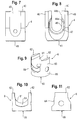
- the bottom section 44a has a substantially circular or oval shape (see Fig.8 ). It has an enlarged width in order to accommodate a stepped portion of the rod element 16.
- the second recess 49 on the back side in Figs. 4 and 8 , or on the right side in Fig. 6 is of the conventional type having a U-shape. Its width amounts to 5,5 mm in its upper section as well as in its bottom section.
- An edge 47 defined by an intersection of the an inner wall of the bottom section 44a of the first recess 44 with an outer surface of the receiving part 4 is chamfered in order to facilitate insertion of a stepped portion of the rod element 16 upon assembly as will be explained below.
- the pressure element 6 has two leg portions 62, separated by a cylindrical recess 61, and an annular base portion 65.
- the pressure lent further has a substantially cylindrical outer surface 63.
- the cylindrical recess 61 is designed to receive the rigid section 161 of the rod element 16 and therefore has a corresponding width of 5 mm in order to fit the same.
- the cylindrical recess has a longitudinal axis which upon insertion of the pressure element in the first bore 42 of the receiving part 4 is oriented perpendicular to the longitudinal axis of that bore 42.
- the pressure element 6 further has a stop face 64, which is arranged as a plane surface recessed from the generally cylindrical outer surface 63.
- the stop face 64 is arranged to abut on the end face 163 of the stepped portion 162 of the rod element 16, or vice versa.
- the stop face 64 is accordingly shaped as an annular segment, which becomes apparent from the front view of Fig. 10 .
- the end face of the stepped portion is also represented by a plane surface perpendicular to the longitudinal axis of the rod, or of the cylindrical recess respectively.
- the fixation element 8 in this embodiment has at its bottom end an extension 82.
- the extension 82 has a decreased diameter smaller than the threaded section. This decreased diameter allows the stepped portion 162 to be accommodated in the inner space of the first bore 42 of the receiving part 4.
- the length of the extension 82 along the longitudinal direction of the bore 42 is equal to or larger than the height of the step due to the stepped portion 162 of the rod element 16.
- a bottom face of this extension 82 exerts pressure onto the rigid section 161 of the rod element 16, while an angular bottom face (not shown) of the threaded portion of the fixation element 8 may, for example, exert a pressure onto legs 62 of the pressure element 6.
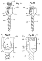
- Fig. 12 shows a cross-sectional view of a bone stabilization device 1 comprising two of the bone anchoring devices 14 as detailed above and a stepped rod element 16.
- Fig. 13 shows an enlarged detail of Fig. 12 .
- the stepped portion 162 in this embodiment represents a flexible section of the rod element 16 comprising for example a helically opened pipe enclosing a bore in which a core being slidable at least at one end thereof with properties similar to EP '243 is disposed.
- the stepped portion extends through respective first recesses 44 (due to the bottom section 44a) and into the internal spaces (due to the stop face 64) of the receiving parts 4 of the corresponding bone anchoring devices 14, for example devices 14e and 14f in Fig. 1 .
- Amounts 100, 101 of length as schematically indicated in Fig. 12 may thus be saved to accommodate the stepped portion between the receiving parts 4.
- the lengths 100, 101 amount each to 2-4 mm.
- the minimum length to accommodate the stepped portion is thus reduced to 9-11 mm, which may comply with the requirements applicable with regard to the L5-S1 stabilization (see Fig. 1 ).
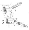
- Figs. 14 - 17 illustrate the assembly process of the bone stabilization device 1.
- Figs. 14, 15 show side views, while Figs. 16 and 17 show perspective views of respective steps.
- the bone screws 2 are inserted into the receiving parts 4 through the first and second bores 42, 43 followed by anchoring the screws 2 in the respective bones.
- the stepped rod element 16 is inserted into recesses 44, 49 with respect to the rigid sections 161 having the smaller width of, e.g., 5 mm.
- the fixation elements 8 are then screwed in but are not yet fastened ( Figs. 14 , 16 ).
- the two receiving parts 4 are shifted towards each other to shorten the mutual distance (indicated by arrows in Fig. 14 ).
- the stepped portion 162 thereby enters each of the bottom sections 44a of the recesses 44 wherein the chamfered edges 47 of the recesses 4 help compensating for slight misalignments.
- FIG. 18-22 Another embodiment is illustrated with respect to Figs. 18-22 .
- This embodiment relates to a monoaxial bone anchoring device 214.
- similar components are denoted with the same numerals. In the following section only different features of the second embodiment are described.
- the bone screw part 202 is integrally formed with the receiving part 204.
- the thread section 22 extends from the bottom end 41 of the receiving part in a fixed direction (i.e., not rotatable prior to fixation).
- the first bore 42 of the receiving part has a bottom end, at which is formed a cylindrical recess 261, which is similarly adopted to receive the rigid section 161 of the rod element 16.
- a plane stop face 264 is oriented towards a section 44a of the inverse key-shaped recess 44, which has the larger width to receive the stepped portion 162 of the rod element 16.
- the plane of the stop face 264 extends perpendicular to the longitudinal axis of the cylindrical recess 261 and - also similar to stop face 164 according the first embodiment - intersects the inner space of the first bore.
- a bone anchoring device 14 comprises: a receiving part 4 for receiving a rod-shaped implant element 16, the receiving part 4, 204 having: a first bore 42 coaxial with a longitudinal axis and extending from a first end 40 of the receiving part, and a recess 44 extending from the first end to accomplish insertion of the rod-shaped implant element; a bone screw 2, 202 having a threaded section 22 for insertion into the bone; a fixation element 8 provided to the first bore 42 to fixate a rigid section 161 of the rod-shaped implant element; wherein the rigid section 161 of the rod-shaped implant element has a first width, and the recess 44 of the receiving part has a second width, the second width being larger than the first width, such that the recess 44 may accommodate a stepped portion 162 of the rod-shaped implant element that has an increased thickness.
- the bone anchoring device 14 further comprises: a second bore 43 provided at a second end 41 of the receiving part 4 opposite to the first end 40, wherein the bone screw 2 has a head section 24 that can be positioned within the second bore 43; a pressure element 6, which is arranged between the head section 24 of the bone screw 2 and the fixation element 8 for transmitting pressure to the head section 24, wherein the pressure element has a cylindrical recess 61 adapted to receive the rigid section 161 of the rod-shaped implant element, the cylindrical recess 61 being arranged to have the first width.
- the receiving part 4 is provided with a cylindrical recess 261 adapted to receive the rigid section 161 of the rod-shaped implant element, and being arranged to have the first width.
- the pressure element 6 or the receiving part 204 further comprises a stop face 64, 264, on which the stepped portion 162 abuts when being received by the recess 44 of the receiving part 4, 204.
- the stop face 64, 264 is oriented substantially perpendicular to a longitudinal axis of the cylindrical recess 61, 261.
- the pressure element 6 comprises a surface 63 having a substantially cylindrical shape adapted to fit with an inner wall of the first bore 42 of the receiving part 4, and the stop face 64 is formed as a plane recessed from the cylindrical surface 63 of the pressure element 6.
- the stop face 64, 264 is represented by a plane surface and has a shape of an annular segment.
- the recess 44 of the receiving part has a shape of a reversed keyhole, its bottom section 44a having the second width and its upper section 44b oriented towards the first end of the receiving part having the first width.
- the recess 44 of the receiving substantially U-shape including a substantially constant width from an upper section of the recess towards its bottom section.
- the receiving part has two recesses, the first recess 44 being provided with at least the bottom section 44a having the second width, and a second recess 49 formed with a substantial U-shape and being arranged with the first width.
- the receiving part 4 has two recesses, the first and a second one of the recesses 44 being provided with at least the bottom section 44a having the second width, respectively.
- the recess 44 of the receiving part 4 has an edge 47 that is chamfered at least in the bottom section 44a thereof.
Landscapes
- Health & Medical Sciences (AREA)
- Orthopedic Medicine & Surgery (AREA)
- Life Sciences & Earth Sciences (AREA)
- Surgery (AREA)
- Neurology (AREA)
- Heart & Thoracic Surgery (AREA)
- Engineering & Computer Science (AREA)
- Biomedical Technology (AREA)
- Nuclear Medicine, Radiotherapy & Molecular Imaging (AREA)
- Medical Informatics (AREA)
- Molecular Biology (AREA)
- Animal Behavior & Ethology (AREA)
- General Health & Medical Sciences (AREA)
- Public Health (AREA)
- Veterinary Medicine (AREA)
- Surgical Instruments (AREA)
- Prostheses (AREA)
Abstract
Description
- The invention relates to a bone anchoring device comprising a receiving part for receiving a rod-shaped implant element, a bone screw having a thread section for insertion into a vertebral body of a spinal column, and a fixation element for fixating the rod-shaped implant element within the receiving part.
- The rod-shaped implant element received by the above bone anchoring device may typically be connected to a further bone anchoring device that is similarly anchored in an adjacent vertebral bone in order to stabilize affected parts of the vertebral column.
- One example of a bone stabilization device including two of such bone anchoring devices and a rod-shaped implant element (in the following also referred to as a "rod element") is described in document
EP 1757243 A1 , by the same applicant. Therein, a rod element is disclosed which is composed of a rigid section, a flexible section, a bore formed within the rod element and a core. The core is provided inside the bore and extends through parts of the rigid sections and through the flexible section. - The flexible section may be made of a cylindrical pipe, into which a helical opening extending from the inner bore to the outer surface is formed. The resultant flexible section is characterized by its axial compression or expansion stiffness. The stiffness is achieved by a combination of pitch, web thickness and used biocompatible material's elasticity.
- The core may freely slide inside the bore in axial direction at least with regard to one of its ends. Thereby, the free end is guided in a rigid section adjacent to the flexible section. The bending stiffness of the core is bigger than of the flexible section itself. Hence, the bending characteristics of the rod element are determined mainly by the core.
- According to
EP 1757243 A1 , due to the presence of a bore which accommodates the core, the diameter or width of the rod element increases as compared with a common rod element, in which flexible components are not utilized. - The one specific bone anchoring device designed to receive the end section of the rod element is provided with small openings instead of the recesses. The end section of the rod element can be introduced through the openings, whose widths correspond to the reduced width of the end section.
- It is an object to provide an improved bone anchoring device, which provides an enhanced flexibility with regard to a stabilization device including a rod element. It is further an object to provide a reliable bone anchoring device which facilitates the implantation of stabilization devices in cases where distance requirements with regard to two adjacently placed bone anchoring devices become very strong. I.e., cases where the mutual distances of those devices are considerably reduced.
- These and other objects are solved by a bone anchoring device for use in trauma or spinal surgery comprising the features according to claim 1. Further advantageous aspects and embodiments become apparent from the appended claims.
- According to one aspect, there is provided a bone anchoring device having a receiving part for insertion of a rod-shaped implant element (in the following also referred to as a "rod element"). The recess extends from a first (upper) end of the receiving part towards a bottom section. At least in its bottom section, the recess attains a width (first width), which is larger than that of a section of the rod element (second width), which is to be fixated by the fixation element.
- In another aspect, The receiving part is employed in conjunction with a rod element provided with a stepped portion. Therein, the rigid section intended to fixate the rod element by the fixation element has the first smaller width and the stepped portion substantially has the second larger width. Consequently, the stepped portion fits in the recess and the rigid portion fits to inner fixation or locking means provided within the receiving part.
- Hence, there is no play and the reliability of the anchoring device and the fixation of the rod element is increased by a quasi form-fit connection. This kind of connection may even improve the behaviour of the device with regard to strong forces exerted on the rod element in axial direction, which might else act to slip the rod through the receiving part.
- When using such a stepped rod element in the recess, the minimum distance between the bone anchoring device is reduced. As will be described in the embodiments below, the stepped portion may represent a flexible section of the rod element. Thereby, in order to maintain desired properties like bending, compression, expansion, torsion stiffness, etc., in combination with fatigue strength, a minimum length of the flexible section is needed.
- In case the mutual distance of two adjacent bone anchoring device (more specifically: of two opposing surfaces of adjacent receiving parts) would decrease below that minimum length, a bone anchoring device as proposed herein may be utilized to increase the usable length for the flexible section by virtue of the recess being enlarged in width to receive portions of the flexible section.
- According to another aspect related to a polyaxial anchoring device, a pressure element is provided which serves to transmit pressure exerted by the fixation element to a head section of the bone screw. The head section can be positioned in a bore at the bottom end of the receiving part. The pressure element has a cylindrical recess adapted to receive the rigid section of the rod element. The cylindrical recess has the first smaller width corresponding to the width of the rod element. The pressure element according to this aspect is further provided with a stop face. The stop face is designed to engage with an end face of the stepped portion of the rod element.
- In an alternative aspect related to a monoaxial anchoring device, a cylindrical recess is provided at a bottom portion of a bore of the receiving part and is adapted to receive the rigid section of the rod element. Similar to the previous aspect, the cylindrical recess has the first smaller width corresponding to the width of the rod element. Further a stop face is oriented towards the recess having the larger width.
- In one specific embodiment, the stop face is formed as a plane surface recessed from a generally cylindrically shaped surface of the pressure element.
- According to this aspect, the pressure element may provide a form-fit connection with regard to the stepped rod element as well as with regard to a spherically or cylindrically shaped head section of the bone screw. Due to the recessed stop face, the stepped portion may reach into the inner space of the first bore formed in the receiving part, such that even more length can be reserved for the accommodating the flexible section of the rod element, i.e., the mutual distance of the anchoring devices can be further reduced.
- The invention will be better understood with reference to specific embodiments of the invention when taken in conjunction with the accompanying drawings. Therein,
- Fig. 1
- shows an illustration of the spinal column;
- Fig. 2
- shows an explosion view of a bone anchoring device according to an embodiment of the invention;
- Fig. 3
- same as
Fig. 2 , but in an assembled state; - Fig. 4
- shows in an enlarged perspective view a receiving part of the device according to
Fig. 2 ; - Fig. 5
- shows a top view of the receiving part of
Fig. 4 ; - Fig. 6
- shows a cross-sectional view of the receiving part according to
Fig. 4 ; - Fig. 7
- shows a side view of the receiving part according to
Fig. 4 ; - Fig. 8
- shows a front view of the receiving part according to
Fig. 4 ; - Fig. 9
- shows in an enlarged perspective view a pressure element of the device according to
Fig. 2 ; - Fig. 10
- shows a front view of the pressure element according to
Fig. 9 ; - Fig. 11
- shows a side view of the pressure element according to
Fig. 9 ; - Fig. 12
- shows a cross sectional profile of a bone stabilization device including the bone anchoring device of
Fig. 2 ; - Fig. 13
- shows an enlarged portion of
Fig. 12 ; - Fig. 14
- shows a first step of assembling the bone stabilization device of
Fig. 12 in a side view; - Fig. 15
- same as
Fig 14 , but with regard to a second (final) step of assembly; - Fig. 16
- same as
Fig. 14 , but in a perspective view; - Fig. 17
- same as
Fig. 15 , but in a perspective view, - Fig. 18
- shows an exploded view of a bone anchoring device according to a second embodiment of the invention;
- Fig. 19
- same as
Fig. 18 , but in a perspective view with the fixation screw being screwed-in; - Fig. 20
- shows in an enlarged front view a receiving part of the device according to
Fig. 18 ; - Fig. 21
- same as
Fig. 20 , but with regard to a sectional view of the receiving part; - Fig. 22
- shows a sectional view of the bone stabilization device according to the second embodiment.
-
Fig. 1 shows a lower part of the spine anatomy in conjunction with variously positionedbone anchoring devices 14a - 14f. The bone anchoring devices each comprise a bone screw and a receiving part for receiving and fixing, e.g., a head section of the bone screw. Each of thebone anchoring devices 14a - 14f is anchored in one vertebrae of either the thoracic or lumbar spine. - As becomes apparent from
Fig. 1 , the interpedicular distance between two adjacentbone anchoring devices bone anchoring devices rod element 16 designed to furnish the stabilization by connecting adjacent ones of theanchoring devices 14a - 14f, and which is provided with flexibility and bending characteristics, must preserve a minimum length for a respective flexible section. - Hence, when considering the lower lumbar part, a flexible section requiring a length of, e.g., 15 mm cannot easily be positioned between respective receiving parts of conventional bone anchoring devices. It has to be noted that a typical receiving part may also contribute further 6-12 mm to the amount of needed distance.
-
Figs. 2 and 3 show an embodiment of abone anchoring device 14 as proposed herein.Fig. 2 reveals an explosion view of the parts involved in a disassembled state, whileFig. 3 shows the device in an assembled state. First, the basic parts of the device which are partly known in the art will be described. - The
bone anchoring device 14 comprises abone screw 2, a receivingpart 4, apressure element 6 and a fixation element (screw) 8. Thebone screw 2 has athread section 22 for insertion into the bone e.g., a vertebral body (not shown), and ahead section 24. In this embodiment, thebone screw 2 has a sphericallyshaped head section 24, but the invention shall not be limited to the specific shape and function of thehead section 24 and/or thethread section 22. The materials selected for the components may be any biocompatible material or metals such as Titanium or Titanium alloy. - The receiving
part 4 is of substantially symmetric form and has afirst end 40 and asecond end 41, which has a tapered profile. From thefirst end 40, there extends afirst bore 42 to define an inner space of the receivingpart 4, which also is of substantially cylindrical shape. At an upper portion of an inner wall of thebore 42, aninner thread 45 is formed which may engage with a correspondingouter thread 81 of the fixation element 8 (see alsoFigs. 4-8 ). - The
pressure element 6 is positioned within thefirst bore 42 between thefixation element 8 and thehead section 24 of thebone screw 2. Thebone screw 2 is accommodated within asecond bore 43 adjacent to thefirst bore 42 and is positioned at thesecond end 41 opposite to thefirst end 40 of the receivingpart 4. Thepressure element 6 is provided with a bottom surface 69 (not shown in detail), which in this specific embodiment is arranged to yield a form-fit connection with the spherically shaped surface of thehead section 24 of the bone screw 2 (see alsoFigs. 9-11 ). - It may be noted herein that the specific type of connection of the
bone screw 2 as described above refers to a polyaxial bone anchoring device. However, those who are skilled in the art will readily recognize that the function and effects of the invention to be explained are similarly applicable to monoaxial bone anchoring devices described below with regard to a second embodiment. - Upon screwing-in the
fixation element 8 into thethread 45 of the receivingpart 4, pressure is exerted onto therod element 16 inserted into receivingpart 4. The pressure is then transmitted further to thepressure element 6 in order to lock thebone screw 2 by means of frictional force. - Next, the details of a modification as proposed herein will be described with particular reference to
Figs. 4-8 , which show enlarged views of the receivingpart 4. - The receiving
part 4 is provided with tworecesses first end 40. The recesses define twolegs 46 of the receivingpart 4 and serve to insert therod element 16 into the receivingpart 4. Thefirst recess 44 has substantially the shape of a reversed keyhole. I.e., thefirst recess 44 has abottom section 44a and anupper section 44b, wherein the bottom section has a larger width of 7,5 mm (diameter as measured in a direction perpendicular to the axis of the inserted rod element and perpendicular to the longitudinal axis of the receiving part 4), and the upper section has a smaller width of 5,5 mm. - The
bottom section 44a has a substantially circular or oval shape (seeFig.8 ). It has an enlarged width in order to accommodate a stepped portion of therod element 16. Thesecond recess 49 on the back side inFigs. 4 and8 , or on the right side inFig. 6 is of the conventional type having a U-shape. Its width amounts to 5,5 mm in its upper section as well as in its bottom section. - An
edge 47 defined by an intersection of the an inner wall of thebottom section 44a of thefirst recess 44 with an outer surface of the receivingpart 4 is chamfered in order to facilitate insertion of a stepped portion of therod element 16 upon assembly as will be explained below. - Next, details of the
pressure element 6 modified as proposed herein are explained with reference toFigs. 9-11 . Thepressure element 6 has twoleg portions 62, separated by acylindrical recess 61, and anannular base portion 65. The pressure lent further has a substantially cylindricalouter surface 63. Thecylindrical recess 61 is designed to receive therigid section 161 of therod element 16 and therefore has a corresponding width of 5 mm in order to fit the same. The cylindrical recess has a longitudinal axis which upon insertion of the pressure element in thefirst bore 42 of the receivingpart 4 is oriented perpendicular to the longitudinal axis of that bore 42. - The
pressure element 6 further has astop face 64, which is arranged as a plane surface recessed from the generally cylindricalouter surface 63. Thestop face 64 is arranged to abut on theend face 163 of the steppedportion 162 of therod element 16, or vice versa. Thestop face 64 is accordingly shaped as an annular segment, which becomes apparent from the front view ofFig. 10 . Preferably, the end face of the stepped portion is also represented by a plane surface perpendicular to the longitudinal axis of the rod, or of the cylindrical recess respectively. - It may be noted that the
fixation element 8 in this embodiment has at its bottom end anextension 82. Theextension 82 has a decreased diameter smaller than the threaded section. This decreased diameter allows the steppedportion 162 to be accommodated in the inner space of thefirst bore 42 of the receivingpart 4. The length of theextension 82 along the longitudinal direction of thebore 42 is equal to or larger than the height of the step due to the steppedportion 162 of therod element 16. - A bottom face of this
extension 82 exerts pressure onto therigid section 161 of therod element 16, while an angular bottom face (not shown) of the threaded portion of thefixation element 8 may, for example, exert a pressure ontolegs 62 of thepressure element 6. -
Fig. 12 shows a cross-sectional view of a bone stabilization device 1 comprising two of thebone anchoring devices 14 as detailed above and a steppedrod element 16.Fig. 13 shows an enlarged detail ofFig. 12 . The steppedportion 162 in this embodiment represents a flexible section of therod element 16 comprising for example a helically opened pipe enclosing a bore in which a core being slidable at least at one end thereof with properties similar to EP '243 is disposed. - The stepped portion extends through respective first recesses 44 (due to the
bottom section 44a) and into the internal spaces (due to the stop face 64) of the receivingparts 4 of the correspondingbone anchoring devices 14, forexample devices Fig. 1 .Amounts Fig. 12 may thus be saved to accommodate the stepped portion between the receivingparts 4. For example, thelengths Fig. 1 ). -
Figs. 14 - 17 illustrate the assembly process of the bone stabilization device 1.Figs. 14, 15 show side views, whileFigs. 16 and17 show perspective views of respective steps. First, the bone screws 2 are inserted into the receivingparts 4 through the first andsecond bores screws 2 in the respective bones. Then, the steppedrod element 16 is inserted intorecesses rigid sections 161 having the smaller width of, e.g., 5 mm. Thefixation elements 8 are then screwed in but are not yet fastened (Figs. 14 ,16 ). - Next, the two receiving
parts 4 are shifted towards each other to shorten the mutual distance (indicated by arrows inFig. 14 ). The steppedportion 162 thereby enters each of thebottom sections 44a of therecesses 44 wherein the chamfered edges 47 of therecesses 4 help compensating for slight misalignments. - Finally, the end faces 163 of the stepped
portions 162 abut on the stop faces 64 of the pressure elements 6 (Figs. 15 ,17 ). - Another embodiment is illustrated with respect to
Figs. 18-22 . This embodiment relates to a monoaxialbone anchoring device 214. As compared with the first embodiment, similar components are denoted with the same numerals. In the following section only different features of the second embodiment are described. - In this embodiment, the
bone screw part 202 is integrally formed with the receivingpart 204. Thus thethread section 22 extends from thebottom end 41 of the receiving part in a fixed direction (i.e., not rotatable prior to fixation). Hence, contrary to the first embodiment, there is neither a pressure element nor second bore present in this anchoring device. Instead, thefirst bore 42 of the receiving part has a bottom end, at which is formed a cylindrical recess 261, which is similarly adopted to receive therigid section 161 of therod element 16. - Similar to the first embodiment, a
plane stop face 264 is oriented towards asection 44a of the inverse key-shapedrecess 44, which has the larger width to receive the steppedportion 162 of therod element 16. The plane of thestop face 264 extends perpendicular to the longitudinal axis of the cylindrical recess 261 and - also similar to stop face 164 according the first embodiment - intersects the inner space of the first bore. - It will become apparent to the person skilled in the art, that the modifications proposed herein may be embodied with various other configurations while yielding similar effects without departing from the scope as set forth in the appended claims.
- According to one aspect, a
bone anchoring device 14 comprises: a receivingpart 4 for receiving a rod-shapedimplant element 16, the receivingpart first bore 42 coaxial with a longitudinal axis and extending from afirst end 40 of the receiving part, and arecess 44 extending from the first end to accomplish insertion of the rod-shaped implant element; abone screw section 22 for insertion into the bone; afixation element 8 provided to the first bore 42 to fixate arigid section 161 of the rod-shaped implant element; wherein therigid section 161 of the rod-shaped implant element has a first width, and therecess 44 of the receiving part has a second width, the second width being larger than the first width, such that therecess 44 may accommodate a steppedportion 162 of the rod-shaped implant element that has an increased thickness. - According to a second aspect, the
bone anchoring device 14 according to the first aspect further comprises: asecond bore 43 provided at asecond end 41 of the receivingpart 4 opposite to thefirst end 40, wherein thebone screw 2 has ahead section 24 that can be positioned within thesecond bore 43; apressure element 6, which is arranged between thehead section 24 of thebone screw 2 and thefixation element 8 for transmitting pressure to thehead section 24, wherein the pressure element has acylindrical recess 61 adapted to receive therigid section 161 of the rod-shaped implant element, thecylindrical recess 61 being arranged to have the first width. - According to a third aspect, in the
bone anchoring device 14 according to the first aspect, the receivingpart 4 is provided with a cylindrical recess 261 adapted to receive therigid section 161 of the rod-shaped implant element, and being arranged to have the first width. - According to a fourth aspect, in the
bone anchoring device 14 according to the second or third aspects, thepressure element 6 or the receivingpart 204 further comprises astop face portion 162 abuts when being received by therecess 44 of the receivingpart - According to a fifth aspect, in the
bone anchoring device 14 according to the fourth aspect, thestop face cylindrical recess 61, 261. - According to a sixth aspect, in the
bone anchoring device 14 according to any one of the fourth or fifth aspects, thepressure element 6 comprises asurface 63 having a substantially cylindrical shape adapted to fit with an inner wall of thefirst bore 42 of the receivingpart 4, and thestop face 64 is formed as a plane recessed from thecylindrical surface 63 of thepressure element 6. - According to a seventh aspect, in the
bone anchoring device 14 according to any one of the fourth to sixth aspects, thestop face - According to an eighth aspect, in the
bone anchoring device 14 according to any one of the preceding aspects, therecess 44 of the receiving part has a shape of a reversed keyhole, itsbottom section 44a having the second width and itsupper section 44b oriented towards the first end of the receiving part having the first width. - According to a ninth aspect, in the
bone anchoring device 14 according to any one of the preceding aspects, therecess 44 of the receiving substantially U-shape including a substantially constant width from an upper section of the recess towards its bottom section. - According to a tenth aspect, in the
bone anchoring device 14 according to any one of the preceding aspects, the receiving part has two recesses, thefirst recess 44 being provided with at least thebottom section 44a having the second width, and asecond recess 49 formed with a substantial U-shape and being arranged with the first width. - According to an eleventh aspect, in the
bone anchoring device 14 according to any one of the preceding aspects, the receivingpart 4 has two recesses, the first and a second one of therecesses 44 being provided with at least thebottom section 44a having the second width, respectively. - According to a twelfth aspect, in the
bone anchoring device 14 according to any one of the preceding aspects, therecess 44 of the receivingpart 4 has anedge 47 that is chamfered at least in thebottom section 44a thereof.
Claims (7)
- A bone stabilization device (14), comprising:at least one bone anchoring device (14) comprising:(a) a receiving part (4) for receiving a rod-shaped implant element (16), the receiving part (4, 204) having:- a first bore (42) coaxial with a longitudinal axis and extending from a first end (40) of the receiving part, and- a recess (44) extending from the first end to accomplish insertion of the rod-shaped implant element (16);(b) a bone screw (2, 202) having a threaded section (22) for insertion into the bone;(c) a fixation element (8) provided to the first bore (42) to fixate a rigid section (161) of the rod-shaped implant element;the rod-shaped implant element (16), which further comprises(d) a rigid section (161) to be fixated by the fixation element (8) of bone anchoring device, wherein the rigid section (161) has a first width;(e) a stepped portion (162), having a thickness such as to be received by the bottom section (44a) of the recess (44) of the receiving part (4) of the bone anchoring device (14);wherein the recess(44) of the receiving part has a second width larger than the first width, such that the recess (44) may accommodate the stepped portion (162) of the rod-shaped implant element that has an increased thickness.
- The bone stabilization device (1) according to claim 1,
wherein the bone anchoring device (14) further comprises a pressure element (6) having a cylindrical recess (61) for receiving the rigid section (161) of the rod-shaped implant element and a stop face (64),
wherein the stepped portion (162) of the rod-shaped implant element (16) has an end face (163) arranged to abut on the stop face (64) of the pressure element (6). - The bone stabilization device (1) according to claim 1,
wherein the receiving part (4) is provided with a cylindrical recess (261) at a bottom end of the first bore (42), the cylindrical recess (261) being adapted to receive the rigid section (161) of the rod-shaped implant element (16), the bone screw (202) being integrally formed with the receiving part (4). - The bone stabilization device (1) according to claim 3,
wherein the receiving part (204) further comprises a stop face (264), on which the stepped portion (162), or an end face (163) thereof, abuts when being received by the recess (44) of the receiving part (204). - The bone stabilization device (1) according to one of claims 2 or 4, wherein the stop face (64, 264) is oriented substantially perpendicular to a longitudinal axis of the cylindrical recess (61, 261).
- The bone stabilization device (1) according to any one of claims 2 or 5, when referring back to claim 2, wherein
the pressure element (6) comprises a surface (63) having a substantially cylindrical shape adapted to fit with an inner wall of the first bore (42) of the receiving part (4), and
the stop face (64) is formed as a plane recessed from the cylindrical surface (63) of the pressure element (6). - The bone stabilization device (1) according to any one of claims 2, 5, when referring back to claim 2, or 6,
wherein a second bore (43) provided at a second end (41) of the receiving part (4) opposite to the first end (40), wherein the bone screw (2) has a head section (24) that can be positioned within the second bore (43); and
the pressure element (6) is arranged between the head section (24) of the bone screw (2) and the fixation element (8) for transmitting pressure to the head section (24).
Applications Claiming Priority (1)
| Application Number | Priority Date | Filing Date | Title |
|---|---|---|---|
| EP07019942A EP2047812B1 (en) | 2007-10-11 | 2007-10-11 | Bone anchoring device |
Related Parent Applications (1)
| Application Number | Title | Priority Date | Filing Date |
|---|---|---|---|
| EP07019942.7 Division | 2007-10-11 |
Publications (2)
| Publication Number | Publication Date |
|---|---|
| EP2380513A1 true EP2380513A1 (en) | 2011-10-26 |
| EP2380513B1 EP2380513B1 (en) | 2013-03-20 |
Family
ID=39204607
Family Applications (3)
| Application Number | Title | Priority Date | Filing Date |
|---|---|---|---|
| EP11152560A Not-in-force EP2335624B1 (en) | 2007-10-11 | 2007-10-11 | Bone anchoring device |
| EP07019942A Not-in-force EP2047812B1 (en) | 2007-10-11 | 2007-10-11 | Bone anchoring device |
| EP11174731A Not-in-force EP2380513B1 (en) | 2007-10-11 | 2007-10-11 | Bone stabilization device |
Family Applications Before (2)
| Application Number | Title | Priority Date | Filing Date |
|---|---|---|---|
| EP11152560A Not-in-force EP2335624B1 (en) | 2007-10-11 | 2007-10-11 | Bone anchoring device |
| EP07019942A Not-in-force EP2047812B1 (en) | 2007-10-11 | 2007-10-11 | Bone anchoring device |
Country Status (7)
| Country | Link |
|---|---|
| US (2) | US8394126B2 (en) |
| EP (3) | EP2335624B1 (en) |
| JP (2) | JP5187897B2 (en) |
| KR (1) | KR101586832B1 (en) |
| CN (2) | CN102715944B (en) |
| ES (3) | ES2379287T3 (en) |
| TW (1) | TWI444169B (en) |
Cited By (4)
| Publication number | Priority date | Publication date | Assignee | Title |
|---|---|---|---|---|
| US9918745B2 (en) | 2009-06-15 | 2018-03-20 | Roger P. Jackson | Polyaxial bone anchor with pop-on shank and winged insert with friction fit compressive collet |
| US9980753B2 (en) | 2009-06-15 | 2018-05-29 | Roger P Jackson | pivotal anchor with snap-in-place insert having rotation blocking extensions |
| US10194951B2 (en) | 2005-05-10 | 2019-02-05 | Roger P. Jackson | Polyaxial bone anchor with compound articulation and pop-on shank |
| US10383660B2 (en) | 2007-05-01 | 2019-08-20 | Roger P. Jackson | Soft stabilization assemblies with pretensioned cords |
Families Citing this family (60)
| Publication number | Priority date | Publication date | Assignee | Title |
|---|---|---|---|---|
| US7833250B2 (en) | 2004-11-10 | 2010-11-16 | Jackson Roger P | Polyaxial bone screw with helically wound capture connection |
| US7862587B2 (en) | 2004-02-27 | 2011-01-04 | Jackson Roger P | Dynamic stabilization assemblies, tool set and method |
| AU2005304849B8 (en) | 2002-09-06 | 2009-09-03 | Roger P. Jackson | Helical guide and advancement flange with break-off extensions |
| US8876868B2 (en) | 2002-09-06 | 2014-11-04 | Roger P. Jackson | Helical guide and advancement flange with radially loaded lip |
| US7621918B2 (en) | 2004-11-23 | 2009-11-24 | Jackson Roger P | Spinal fixation tool set and method |
| US7377923B2 (en) | 2003-05-22 | 2008-05-27 | Alphatec Spine, Inc. | Variable angle spinal screw assembly |
| US8398682B2 (en) | 2003-06-18 | 2013-03-19 | Roger P. Jackson | Polyaxial bone screw assembly |
| US8814911B2 (en) | 2003-06-18 | 2014-08-26 | Roger P. Jackson | Polyaxial bone screw with cam connection and lock and release insert |
| US8936623B2 (en) | 2003-06-18 | 2015-01-20 | Roger P. Jackson | Polyaxial bone screw assembly |
| US8377102B2 (en) | 2003-06-18 | 2013-02-19 | Roger P. Jackson | Polyaxial bone anchor with spline capture connection and lower pressure insert |
| US8137386B2 (en) | 2003-08-28 | 2012-03-20 | Jackson Roger P | Polyaxial bone screw apparatus |
| US7776067B2 (en) | 2005-05-27 | 2010-08-17 | Jackson Roger P | Polyaxial bone screw with shank articulation pressure insert and method |
| US7766915B2 (en) | 2004-02-27 | 2010-08-03 | Jackson Roger P | Dynamic fixation assemblies with inner core and outer coil-like member |
| US7527638B2 (en) | 2003-12-16 | 2009-05-05 | Depuy Spine, Inc. | Methods and devices for minimally invasive spinal fixation element placement |
| US7179261B2 (en) | 2003-12-16 | 2007-02-20 | Depuy Spine, Inc. | Percutaneous access devices and bone anchor assemblies |
| US11419642B2 (en) | 2003-12-16 | 2022-08-23 | Medos International Sarl | Percutaneous access devices and bone anchor assemblies |
| CA2701522C (en) | 2004-02-27 | 2012-05-15 | Roger P. Jackson | Orthopedic implant rod reduction tool set and method |
| US8152810B2 (en) | 2004-11-23 | 2012-04-10 | Jackson Roger P | Spinal fixation tool set and method |
| US7160300B2 (en) | 2004-02-27 | 2007-01-09 | Jackson Roger P | Orthopedic implant rod reduction tool set and method |
| US11241261B2 (en) | 2005-09-30 | 2022-02-08 | Roger P Jackson | Apparatus and method for soft spinal stabilization using a tensionable cord and releasable end structure |
| US8926672B2 (en) | 2004-11-10 | 2015-01-06 | Roger P. Jackson | Splay control closure for open bone anchor |
| US8444681B2 (en) | 2009-06-15 | 2013-05-21 | Roger P. Jackson | Polyaxial bone anchor with pop-on shank, friction fit retainer and winged insert |
| US8308782B2 (en) | 2004-11-23 | 2012-11-13 | Jackson Roger P | Bone anchors with longitudinal connecting member engaging inserts and closures for fixation and optional angulation |
| US9168069B2 (en) | 2009-06-15 | 2015-10-27 | Roger P. Jackson | Polyaxial bone anchor with pop-on shank and winged insert with lower skirt for engaging a friction fit retainer |
| WO2006057837A1 (en) | 2004-11-23 | 2006-06-01 | Jackson Roger P | Spinal fixation tool attachment structure |
| US9216041B2 (en) | 2009-06-15 | 2015-12-22 | Roger P. Jackson | Spinal connecting members with tensioned cords and rigid sleeves for engaging compression inserts |
| US7901437B2 (en) | 2007-01-26 | 2011-03-08 | Jackson Roger P | Dynamic stabilization member with molded connection |
| US10076361B2 (en) | 2005-02-22 | 2018-09-18 | Roger P. Jackson | Polyaxial bone screw with spherical capture, compression and alignment and retention structures |
| US8105368B2 (en) | 2005-09-30 | 2012-01-31 | Jackson Roger P | Dynamic stabilization connecting member with slitted core and outer sleeve |
| JP2010512178A (en) | 2006-12-08 | 2010-04-22 | ロジャー・ピー・ジャクソン | Tool system for dynamic spinal implants |
| EP2335624B1 (en) * | 2007-10-11 | 2012-08-29 | Biedermann Technologies GmbH & Co. KG | Bone anchoring device |
| JP2012529969A (en) | 2008-08-01 | 2012-11-29 | ロジャー・ピー・ジャクソン | Longitudinal connecting member with tensioning cord with sleeve |
| CN103917181A (en) | 2009-06-15 | 2014-07-09 | 罗杰.P.杰克逊 | Polyaxial Bone Anchor Including Sleeve Stem and Friction Fit Retainer with Low Profile Edge Lock |
| US9668771B2 (en) | 2009-06-15 | 2017-06-06 | Roger P Jackson | Soft stabilization assemblies with off-set connector |
| US8998959B2 (en) | 2009-06-15 | 2015-04-07 | Roger P Jackson | Polyaxial bone anchors with pop-on shank, fully constrained friction fit retainer and lock and release insert |
| US11229457B2 (en) | 2009-06-15 | 2022-01-25 | Roger P. Jackson | Pivotal bone anchor assembly with insert tool deployment |
| EP2485654B1 (en) | 2009-10-05 | 2021-05-05 | Jackson P. Roger | Polyaxial bone anchor with non-pivotable retainer and pop-on shank, some with friction fit |
| US12383311B2 (en) | 2010-05-14 | 2025-08-12 | Roger P. Jackson | Pivotal bone anchor assembly and method for use thereof |
| WO2012024807A1 (en) | 2010-08-26 | 2012-03-01 | Spinesave Ag | Spinal implant set for the dynamic stabilization of the spine |
| GB2507620A (en) | 2010-11-02 | 2014-05-07 | Roger P Jackson | Polyaxial bone anchor with pop-on shank and pivotable retainer |
| KR101296678B1 (en) * | 2011-10-26 | 2013-08-16 | 서승우 | anti bleeding element and bone screw for anti bleeding having thereof |
| US8911479B2 (en) | 2012-01-10 | 2014-12-16 | Roger P. Jackson | Multi-start closures for open implants |
| US8911478B2 (en) | 2012-11-21 | 2014-12-16 | Roger P. Jackson | Splay control closure for open bone anchor |
| US10058354B2 (en) | 2013-01-28 | 2018-08-28 | Roger P. Jackson | Pivotal bone anchor assembly with frictional shank head seating surfaces |
| US8852239B2 (en) | 2013-02-15 | 2014-10-07 | Roger P Jackson | Sagittal angle screw with integral shank and receiver |
| EP3038552B1 (en) | 2013-09-01 | 2020-08-12 | Carbofix In Orthopedics LLC | Composite material spinal implant |
| US9566092B2 (en) | 2013-10-29 | 2017-02-14 | Roger P. Jackson | Cervical bone anchor with collet retainer and outer locking sleeve |
| US9717533B2 (en) | 2013-12-12 | 2017-08-01 | Roger P. Jackson | Bone anchor closure pivot-splay control flange form guide and advancement structure |
| US9451993B2 (en) | 2014-01-09 | 2016-09-27 | Roger P. Jackson | Bi-radial pop-on cervical bone anchor |
| US10064658B2 (en) | 2014-06-04 | 2018-09-04 | Roger P. Jackson | Polyaxial bone anchor with insert guides |
| US9597119B2 (en) | 2014-06-04 | 2017-03-21 | Roger P. Jackson | Polyaxial bone anchor with polymer sleeve |
| CN107072698B (en) * | 2014-09-01 | 2020-01-03 | 碳固定因骨科有限责任公司 | Composite spinal implant |
| US10888357B2 (en) * | 2016-02-29 | 2021-01-12 | Warsaw Orthopedic, Inc. | Spinal implant system and method |
| US10531903B2 (en) * | 2016-12-06 | 2020-01-14 | DePuy Synthes Products, Inc. | Orthopedic break-off screws, tools for inserting such screws, and related systems and methods |
| US10893915B2 (en) | 2019-05-07 | 2021-01-19 | Warsaw Orthopedic, Inc. | Surgical system and method |
| US11589905B2 (en) * | 2018-07-19 | 2023-02-28 | Warsaw Orthopedic, Inc. | Set screw sensor placement |
| CN109077789B (en) * | 2018-11-02 | 2024-02-13 | 河北瑞鹤医疗器械有限公司 | Pedicle screw |
| US11583318B2 (en) | 2018-12-21 | 2023-02-21 | Paradigm Spine, Llc | Modular spine stabilization system and associated instruments |
| WO2022165208A1 (en) * | 2021-01-29 | 2022-08-04 | Acument Intellectual Properties, Llc | Minimized lateral clearance ball stud joint |
| CN117717404B (en) * | 2024-02-08 | 2024-05-10 | 中国人民解放军总医院第一医学中心 | Bone screw combiner and spinal stabilization system |
Citations (4)
| Publication number | Priority date | Publication date | Assignee | Title |
|---|---|---|---|---|
| WO2006066685A1 (en) * | 2004-12-17 | 2006-06-29 | Zimmer Gmbh | Intervertebral stabilisation system |
| EP1757243A1 (en) | 2005-08-24 | 2007-02-28 | BIEDERMANN MOTECH GmbH | Rod-shaped implant element for the application in spine surgery or trauma surgery and stabilization device with such a rod-shaped implant element |
| EP1815812A1 (en) * | 2006-02-03 | 2007-08-08 | Spinelab AG | Spinal implant |
| US20070191842A1 (en) * | 2006-01-30 | 2007-08-16 | Sdgi Holdings, Inc. | Spinal fixation devices and methods of use |
Family Cites Families (39)
| Publication number | Priority date | Publication date | Assignee | Title |
|---|---|---|---|---|
| DE3614101C1 (en) * | 1986-04-25 | 1987-10-22 | Juergen Prof Dr Med Harms | Pedicle screw |
| US4887596A (en) * | 1988-03-02 | 1989-12-19 | Synthes (U.S.A.) | Open backed pedicle screw |
| DE3923996A1 (en) * | 1989-07-20 | 1991-01-31 | Lutz Biedermann | RECORDING PART FOR JOINTLY CONNECTING TO A SCREW FOR MAKING A PEDICLE SCREW |
| US5120171A (en) * | 1990-11-27 | 1992-06-09 | Stuart Surgical | Bone screw with improved threads |
| FR2676911B1 (en) * | 1991-05-30 | 1998-03-06 | Psi Ste Civile Particuliere | INTERVERTEBRAL STABILIZATION DEVICE WITH SHOCK ABSORBERS. |
| DE4303770C1 (en) * | 1993-02-09 | 1994-05-26 | Plus Endoprothetik Ag Rotkreuz | Stiffening and correction system for spinal vertebrae - comprises screw-ended holders with connecting rod supporting clamped distance pieces. |
| US5437669A (en) * | 1993-08-12 | 1995-08-01 | Amei Technologies Inc. | Spinal fixation systems with bifurcated connectors |
| US5474551A (en) * | 1994-11-18 | 1995-12-12 | Smith & Nephew Richards, Inc. | Universal coupler for spinal fixation |
| US5957953A (en) * | 1996-02-16 | 1999-09-28 | Smith & Nephew, Inc. | Expandable suture anchor |
| DE19617362C2 (en) * | 1996-04-30 | 1999-06-10 | Harms Juergen | Anchoring element |
| US5728098A (en) * | 1996-11-07 | 1998-03-17 | Sdgi Holdings, Inc. | Multi-angle bone screw assembly using shape-memory technology |
| US6254602B1 (en) * | 1999-05-28 | 2001-07-03 | Sdgi Holdings, Inc. | Advanced coupling device using shape-memory technology |
| US6280442B1 (en) * | 1999-09-01 | 2001-08-28 | Sdgi Holdings, Inc. | Multi-axial bone screw assembly |
| US20020133155A1 (en) * | 2000-02-25 | 2002-09-19 | Ferree Bret A. | Cross-coupled vertebral stabilizers incorporating spinal motion restriction |
| US6565566B1 (en) * | 2000-03-22 | 2003-05-20 | Spinal Concepts, Inc. | Sacral screw assembly and method |
| FR2810533B1 (en) * | 2000-06-22 | 2003-01-10 | Emmanuel Bockx | DEVICE FOR ORIENTABLE FIXATION OF A CONNECTION BAR BY MEANS OF AT LEAST ONE PEDICLE SCREW FOR VERTEBRAL STABILITY |
| US6875212B2 (en) * | 2000-06-23 | 2005-04-05 | Vertelink Corporation | Curable media for implantable medical device |
| FR2830433B1 (en) * | 2001-10-04 | 2005-07-01 | Stryker Spine | ASSEMBLY FOR OSTEOSYNTHESIS OF THE SPINACH COMPRISING AN ANCHORING MEMBER HEAD AND A TOOL FOR HEAD FIXING |
| FR2833151B1 (en) * | 2001-12-12 | 2004-09-17 | Ldr Medical | BONE ANCHORING IMPLANT WITH POLYAXIAL HEAD |
| JP4047112B2 (en) * | 2002-09-12 | 2008-02-13 | 昭和医科工業株式会社 | Rod part fixing structure of vertebra connecting member |
| US7473267B2 (en) * | 2003-04-25 | 2009-01-06 | Warsaw Orthopedic, Inc. | System and method for minimally invasive posterior fixation |
| BRPI0412290A (en) * | 2003-07-03 | 2006-09-19 | Synthes Gmbh | bone holder for receiving a spinal shaft, system for inserting a spinal shaft, and instruments for inserting an elongated spinal shaft into a U-shaped channel of a bone holder and for manipulating a bone holder |
| US8858599B2 (en) * | 2004-06-09 | 2014-10-14 | Warsaw Orthopedic, Inc. | Systems and methods for flexible spinal stabilization |
| WO2006029373A1 (en) * | 2004-09-08 | 2006-03-16 | Nuvasive, Inc. | Systems and methods for performing spinal fixation |
| US20060095037A1 (en) * | 2004-10-29 | 2006-05-04 | Jones Bryan S | Connector assemblies for connecting a bone anchor to a fixation element |
| US20060264937A1 (en) * | 2005-05-04 | 2006-11-23 | White Patrick M | Mobile spine stabilization device |
| US20090093844A1 (en) * | 2005-09-30 | 2009-04-09 | Jackson Roger P | Elastic covered dynamic stabilization connector and assembly |
| US20070161986A1 (en) * | 2005-12-13 | 2007-07-12 | Levy Mark M | Polyaxial fastener assembly |
| DE602005008265D1 (en) | 2005-12-23 | 2008-08-28 | Biedermann Motech Gmbh | Flexible stabilization device for the dynamic stabilization of bones or vertebrae |
| US20070233091A1 (en) * | 2006-02-23 | 2007-10-04 | Naifeh Bill R | Multi-level spherical linkage implant system |
| US8118869B2 (en) * | 2006-03-08 | 2012-02-21 | Flexuspine, Inc. | Dynamic interbody device |
| US7947045B2 (en) * | 2006-10-06 | 2011-05-24 | Zimmer Spine, Inc. | Spinal stabilization system with flexible guides |
| US7892265B2 (en) * | 2006-12-28 | 2011-02-22 | Mi4Spine, Llc | Surgical screw including a body that facilitates bone in-growth |
| US8029544B2 (en) * | 2007-01-02 | 2011-10-04 | Zimmer Spine, Inc. | Spine stiffening device |
| US8029547B2 (en) * | 2007-01-30 | 2011-10-04 | Warsaw Orthopedic, Inc. | Dynamic spinal stabilization assembly with sliding collars |
| US8016832B2 (en) * | 2007-05-02 | 2011-09-13 | Zimmer Spine, Inc. | Installation systems for spinal stabilization system and related methods |
| US20080312697A1 (en) * | 2007-06-15 | 2008-12-18 | Robert Reid, Inc. | System and Method for Polyaxially Adjustable Bone Anchorage |
| EP2335624B1 (en) * | 2007-10-11 | 2012-08-29 | Biedermann Technologies GmbH & Co. KG | Bone anchoring device |
| US20100137908A1 (en) * | 2008-12-01 | 2010-06-03 | Zimmer Spine, Inc. | Dynamic Stabilization System Components Including Readily Visualized Polymeric Compositions |
-
2007
- 2007-10-11 EP EP11152560A patent/EP2335624B1/en not_active Not-in-force
- 2007-10-11 ES ES07019942T patent/ES2379287T3/en active Active
- 2007-10-11 ES ES11152560T patent/ES2394284T3/en active Active
- 2007-10-11 ES ES11174731T patent/ES2415169T3/en active Active
- 2007-10-11 EP EP07019942A patent/EP2047812B1/en not_active Not-in-force
- 2007-10-11 EP EP11174731A patent/EP2380513B1/en not_active Not-in-force
-
2008
- 2008-09-25 US US12/238,347 patent/US8394126B2/en not_active Expired - Fee Related
- 2008-10-07 CN CN201210243237.3A patent/CN102715944B/en not_active Expired - Fee Related
- 2008-10-07 JP JP2008260682A patent/JP5187897B2/en not_active Expired - Fee Related
- 2008-10-07 TW TW097138481A patent/TWI444169B/en not_active IP Right Cessation
- 2008-10-07 CN CN2008101689567A patent/CN101406407B/en not_active Expired - Fee Related
- 2008-10-07 KR KR1020080098269A patent/KR101586832B1/en not_active Expired - Fee Related
-
2013
- 2013-01-15 JP JP2013004467A patent/JP5485423B2/en not_active Expired - Fee Related
- 2013-02-15 US US13/769,005 patent/US9220540B2/en not_active Expired - Fee Related
Patent Citations (4)
| Publication number | Priority date | Publication date | Assignee | Title |
|---|---|---|---|---|
| WO2006066685A1 (en) * | 2004-12-17 | 2006-06-29 | Zimmer Gmbh | Intervertebral stabilisation system |
| EP1757243A1 (en) | 2005-08-24 | 2007-02-28 | BIEDERMANN MOTECH GmbH | Rod-shaped implant element for the application in spine surgery or trauma surgery and stabilization device with such a rod-shaped implant element |
| US20070191842A1 (en) * | 2006-01-30 | 2007-08-16 | Sdgi Holdings, Inc. | Spinal fixation devices and methods of use |
| EP1815812A1 (en) * | 2006-02-03 | 2007-08-08 | Spinelab AG | Spinal implant |
Cited By (4)
| Publication number | Priority date | Publication date | Assignee | Title |
|---|---|---|---|---|
| US10194951B2 (en) | 2005-05-10 | 2019-02-05 | Roger P. Jackson | Polyaxial bone anchor with compound articulation and pop-on shank |
| US10383660B2 (en) | 2007-05-01 | 2019-08-20 | Roger P. Jackson | Soft stabilization assemblies with pretensioned cords |
| US9918745B2 (en) | 2009-06-15 | 2018-03-20 | Roger P. Jackson | Polyaxial bone anchor with pop-on shank and winged insert with friction fit compressive collet |
| US9980753B2 (en) | 2009-06-15 | 2018-05-29 | Roger P Jackson | pivotal anchor with snap-in-place insert having rotation blocking extensions |
Also Published As
| Publication number | Publication date |
|---|---|
| JP5485423B2 (en) | 2014-05-07 |
| JP2013116326A (en) | 2013-06-13 |
| US8394126B2 (en) | 2013-03-12 |
| JP2009090118A (en) | 2009-04-30 |
| TWI444169B (en) | 2014-07-11 |
| EP2380513B1 (en) | 2013-03-20 |
| EP2335624B1 (en) | 2012-08-29 |
| EP2047812A1 (en) | 2009-04-15 |
| US9220540B2 (en) | 2015-12-29 |
| CN102715944B (en) | 2014-12-24 |
| CN101406407B (en) | 2013-02-06 |
| CN102715944A (en) | 2012-10-10 |
| EP2335624A1 (en) | 2011-06-22 |
| TW200916046A (en) | 2009-04-16 |
| US20090131983A1 (en) | 2009-05-21 |
| US20130158605A1 (en) | 2013-06-20 |
| ES2394284T3 (en) | 2013-01-30 |
| KR20090037316A (en) | 2009-04-15 |
| JP5187897B2 (en) | 2013-04-24 |
| CN101406407A (en) | 2009-04-15 |
| EP2047812B1 (en) | 2011-12-14 |
| KR101586832B1 (en) | 2016-01-20 |
| ES2379287T3 (en) | 2012-04-24 |
| ES2415169T3 (en) | 2013-07-24 |
Similar Documents
| Publication | Publication Date | Title |
|---|---|---|
| EP2335624B1 (en) | Bone anchoring device | |
| EP2153786B1 (en) | Modular system for the stabilization of the spinal column | |
| EP2364656B1 (en) | Rod assembly and modular rod system for spinal stabilization | |
| US8795336B2 (en) | Bone anchoring device and stabilization device for bone parts or vertebrae comprising such a bone anchoring device | |
| EP1800614B1 (en) | Dynamic stabilization device for bones or vertebrae | |
| US7717941B2 (en) | Linking element for dynamically stabilizing a spinal fixing system and spinal fixing system comprising same | |
| US8353936B2 (en) | Rod connection in a surgical device and rod-shaped bone stabilization device comprising the same | |
| EP2301456A1 (en) | Device for stabilizing vertebrae and rod connector used therefor | |
| HUP0402255A2 (en) | Damping element and device for stabilisation of adjacent vertebral bodies | |
| EP2720630A1 (en) | Modular bone plate and member of such a modular bone plate | |
| US20110118783A1 (en) | Load-sharing bone anchor having a flexible post and method for dynamic stabilization of the spine | |
| WO2025264319A1 (en) | Modular spinal fixation screw |
Legal Events
| Date | Code | Title | Description |
|---|---|---|---|
| AC | Divisional application: reference to earlier application |
Ref document number: 2047812 Country of ref document: EP Kind code of ref document: P |
|
| AK | Designated contracting states |
Kind code of ref document: A1 Designated state(s): CH DE ES FR GB IT LI |
|
| PUAI | Public reference made under article 153(3) epc to a published international application that has entered the european phase |
Free format text: ORIGINAL CODE: 0009012 |
|
| RAP1 | Party data changed (applicant data changed or rights of an application transferred) |
Owner name: BIEDERMANN TECHNOLOGIES GMBH & CO. KG |
|
| 17P | Request for examination filed |
Effective date: 20120426 |
|
| RIC1 | Information provided on ipc code assigned before grant |
Ipc: A61B 17/70 20060101AFI20120724BHEP |
|
| GRAP | Despatch of communication of intention to grant a patent |
Free format text: ORIGINAL CODE: EPIDOSNIGR1 |
|
| GRAS | Grant fee paid |
Free format text: ORIGINAL CODE: EPIDOSNIGR3 |
|
| GRAA | (expected) grant |
Free format text: ORIGINAL CODE: 0009210 |
|
| AC | Divisional application: reference to earlier application |
Ref document number: 2047812 Country of ref document: EP Kind code of ref document: P |
|
| AK | Designated contracting states |
Kind code of ref document: B1 Designated state(s): CH DE ES FR GB IT LI |
|
| REG | Reference to a national code |
Ref country code: GB Ref legal event code: FG4D |
|
| REG | Reference to a national code |
Ref country code: CH Ref legal event code: EP Ref country code: CH Ref legal event code: NV Representative=s name: NOVAGRAAF INTERNATIONAL SA, CH |
|
| REG | Reference to a national code |
Ref country code: DE Ref legal event code: R096 Ref document number: 602007029270 Country of ref document: DE Effective date: 20130516 |
|
| REG | Reference to a national code |
Ref country code: ES Ref legal event code: FG2A Ref document number: 2415169 Country of ref document: ES Kind code of ref document: T3 Effective date: 20130724 |
|
| PLBE | No opposition filed within time limit |
Free format text: ORIGINAL CODE: 0009261 |
|
| STAA | Information on the status of an ep patent application or granted ep patent |
Free format text: STATUS: NO OPPOSITION FILED WITHIN TIME LIMIT |
|
| 26N | No opposition filed |
Effective date: 20140102 |
|
| REG | Reference to a national code |
Ref country code: DE Ref legal event code: R097 Ref document number: 602007029270 Country of ref document: DE Effective date: 20140102 |
|
| REG | Reference to a national code |
Ref country code: FR Ref legal event code: PLFP Year of fee payment: 9 |
|
| PGFP | Annual fee paid to national office [announced via postgrant information from national office to epo] |
Ref country code: CH Payment date: 20151026 Year of fee payment: 9 Ref country code: DE Payment date: 20151029 Year of fee payment: 9 Ref country code: IT Payment date: 20151026 Year of fee payment: 9 Ref country code: GB Payment date: 20151026 Year of fee payment: 9 |
|
| PGFP | Annual fee paid to national office [announced via postgrant information from national office to epo] |
Ref country code: FR Payment date: 20151026 Year of fee payment: 9 Ref country code: ES Payment date: 20151023 Year of fee payment: 9 |
|
| REG | Reference to a national code |
Ref country code: DE Ref legal event code: R119 Ref document number: 602007029270 Country of ref document: DE |
|
| REG | Reference to a national code |
Ref country code: CH Ref legal event code: PL |
|
| GBPC | Gb: european patent ceased through non-payment of renewal fee |
Effective date: 20161011 |
|
| REG | Reference to a national code |
Ref country code: FR Ref legal event code: ST Effective date: 20170630 |
|
| PG25 | Lapsed in a contracting state [announced via postgrant information from national office to epo] |
Ref country code: CH Free format text: LAPSE BECAUSE OF NON-PAYMENT OF DUE FEES Effective date: 20161031 Ref country code: DE Free format text: LAPSE BECAUSE OF NON-PAYMENT OF DUE FEES Effective date: 20170503 Ref country code: GB Free format text: LAPSE BECAUSE OF NON-PAYMENT OF DUE FEES Effective date: 20161011 Ref country code: FR Free format text: LAPSE BECAUSE OF NON-PAYMENT OF DUE FEES Effective date: 20161102 Ref country code: LI Free format text: LAPSE BECAUSE OF NON-PAYMENT OF DUE FEES Effective date: 20161031 |
|
| PG25 | Lapsed in a contracting state [announced via postgrant information from national office to epo] |
Ref country code: IT Free format text: LAPSE BECAUSE OF NON-PAYMENT OF DUE FEES Effective date: 20161011 |
|
| PG25 | Lapsed in a contracting state [announced via postgrant information from national office to epo] |
Ref country code: ES Free format text: LAPSE BECAUSE OF NON-PAYMENT OF DUE FEES Effective date: 20161012 |
|
| REG | Reference to a national code |
Ref country code: ES Ref legal event code: FD2A Effective date: 20181126 |