EP2380339B1 - Determining an acoustic coupling between a far-end talker signal and a combined signal - Google Patents
Determining an acoustic coupling between a far-end talker signal and a combined signal Download PDFInfo
- Publication number
- EP2380339B1 EP2380339B1 EP09795817.7A EP09795817A EP2380339B1 EP 2380339 B1 EP2380339 B1 EP 2380339B1 EP 09795817 A EP09795817 A EP 09795817A EP 2380339 B1 EP2380339 B1 EP 2380339B1
- Authority
- EP
- European Patent Office
- Prior art keywords
- signal
- far
- end talker
- envelope
- echo
- Prior art date
- Legal status (The legal status is an assumption and is not a legal conclusion. Google has not performed a legal analysis and makes no representation as to the accuracy of the status listed.)
- Active
Links
Images


Classifications
-
- H—ELECTRICITY
- H04—ELECTRIC COMMUNICATION TECHNIQUE
- H04M—TELEPHONIC COMMUNICATION
- H04M9/00—Arrangements for interconnection not involving centralised switching
- H04M9/08—Two-way loud-speaking telephone systems with means for conditioning the signal, e.g. for suppressing echoes for one or both directions of traffic
- H04M9/082—Two-way loud-speaking telephone systems with means for conditioning the signal, e.g. for suppressing echoes for one or both directions of traffic using echo cancellers
-
- H—ELECTRICITY
- H04—ELECTRIC COMMUNICATION TECHNIQUE
- H04R—LOUDSPEAKERS, MICROPHONES, GRAMOPHONE PICK-UPS OR LIKE ACOUSTIC ELECTROMECHANICAL TRANSDUCERS; ELECTRIC HEARING AIDS; PUBLIC ADDRESS SYSTEMS
- H04R3/00—Circuits for transducers
- H04R3/02—Circuits for transducers for preventing acoustic reaction, i.e. acoustic oscillatory feedback
Definitions
- the invention relates to a device for determining an acoustic coupling between a far-end talker signal and a combined signal that comprises an echo of the far-end talker signal and a near-end talker signal.
- the invention also relates to a method for determining an acoustic coupling between a far-end talker signal and a combined signal.
- the invention relates to an acoustic echo canceller, a webcam device, a video conferencing system, and hands-free telephone terminal.
- AECs Acoustic Echo Cancellers
- FR2674389 discloses a device receiving the plurality of transmitted peak envelope signals, received peak envelope signals and peak envelope signals restored by the echo canceller, and supplying the leakage and control coefficient signals to the self-adapting filter.
- the control coefficient ensures optimum convergence of filter according to a single and double voice communication distinction criterion corresponding to the absence or presence of simultaneity of transmitted or received voice signals.
- US2004//057574 discloses the system in which in a microphone signal, the signal component corresponding to, e.g., echo is suppressed using an echo control scheme that estimates the spectral envelope of the echo signal, without having to estimate the waveform for the echo signal.
- the input signal and the microphone signal are spectrally decomposed into multiple bands, where each suppression processing is independently performed on each subband.
- US6625279 disclosed an echo path delay estimating apparatus and method for estimating the echo path delay using decimators and an adaptive filter, so that a short computation time is used by the echo canceller.
- US2004/062386 discloses an apparatus and method for bulk delay insertion prior to echo cancellation, with echo suppression.
- JP2006279191 and JP2006148375 both disclose a device for computing an acoustic coupling based on the power envelopes of the far-end signal and a combined signal.
- a crucial component of an AEC is an adaptive filter, often referred to as an echo filter that models a physical path between a loudspeaker and a microphone and tries to predict an echo on the microphone caused by the loudspeaker.
- a signal of a far-end talker on the opposite side is amplified and fed to the loudspeaker.
- the echo is generated and picked up by the microphone together with the speech signal of a near-end talker, if present.
- the adaptive filter makes a replica of the echo signal, which can be subtracted from the microphone signal. This is done by estimating (a part of) the impulse response between the loudspeaker and the microphone.
- the adaptive filter typically implemented as an N-point transversal filter, updates its coefficients by correlating the residual signal, which is a difference between the microphone signal and the replica of the echo signal, with the input data of the transversal filter.
- the residual signal which is a difference between the microphone signal and the replica of the echo signal
- the adaptive filter will diverge due to the presence of the near-end talker signal. If the far-end talker signal and the near-end talker signal are correlated these problems are more severe.
- a solution to this problem is to reduce the amount of adaptation in case of double talk and in case of severe double talk even to stop the adaptation.
- a well-known solution is to use step-size control like e.g. given in A. Mader, H.
- the invention is defined by the independent claims.
- the dependent claims define advantageous embodiments.
- this object is achieved in that the acoustic coupling is derived from a ratio of changes in an envelope of the combined signal to changes in an envelope of the far-end talker signal in a predetermined time interval.
- the systematic error during double talk an estimation of the acoustic coupling that is too large is not present anymore or at least strongly reduced.
- the envelope of the combined signal and the envelope of the far-end talker signal are obtained from the combined signal by rectifying and averaging on a block basis and the far-end talker signal by rectifying and averaging on the block basis, respectively.
- This method is advantageous for signals with a slow-varying envelope like e.g. speech.
- the envelope of the combined signal and the envelope of the far-end talker signal are derived from a power measurement for the combined signal and the far-end talker signal, respectively, on a block basis. This method is advantageous for signals with a slow-varying envelope like e.g. speech, and can be implemented very efficiently on certain DSP platforms.
- the predetermined time interval is a time interval between successive samples of the far-end talker signal, wherein sampling of the combined signal is aligned with sampling of the far-end talker signal.
- the alignment of the sampling of the combined signal with the far-end talker signal is necessary since the echo at the microphone can be considered as a linear convolution of the loudspeaker signal with the acoustic path that is a function of the acoustic coupling.
- the predetermined time interval comprises a multiplicity of a time interval between the successive samples of the far-end talker signal, wherein sampling of the combined signal is aligned with sampling of the far-end talker signal.
- the device comprises:
- the adaptive filter is a multi-tap filter, wherein the ratio of changes in the envelope of the combined signal to changes in the envelope of the far-end talker signal in the predetermined time interval is determined as a coefficient of the adaptive filter having a largest value.
- a delay between a far-end talker signal and the echo of a far-end talker signal is determined by a location of a tap with a largest value of the adaptive filter that determines the acoustic coupling. In this way the bulk delay that is sometimes present in certain applications can be estimated. This is for example the case in digital TV sets, where the audio is delayed in order to be synchronized with a video.
- the invention further provides an acoustic echo canceller, a webcam device, a video-conferencing system, and a hands-free telephone terminal comprising a device according to the invention.
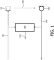
- Fig. 1 shows schematically an embodiment of a device 100 for determining an acoustic coupling 103 according to the invention between a loudspeaker 110 and a microphone 120.
- the loudspeaker 110 is reproducing the far-end talker signal 101.
- the microphone 120 is picking-up a combined signal 102 comprising an echo of the far-end talker signal 101 and a near-end talker signal.
- the acoustic coupling phenomenon between the loudspeaker 110 and the microphone 120 is symbolically depicted by the arrow 130.
- the acoustic coupling 103 is derived from a ratio of changes in an envelope of the combined signal 102 to changes in the envelope of the far-end talker signal 101 in a predetermined time interval.
- the derived acoustic coupling is outputted by the device 100 in the form of a signal 103.
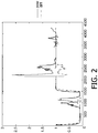
- Fig. 2 shows a plot that illustrates an effect of deriving the acoustic coupling 103 from the ratio of the changes in the envelope of the combined signal 102 to the changes in the envelope of the far-end talker signal 101 in the predetermined time interval.
- An x-axis depicts a time in terms of blocks of signal samples.
- a y-axis depicts the square root of the acoustic coupling.
- a solid line plot shows the square root of the acoustic coupling, wherein the acoustic coupling is derived as the square root of the ratio of the power of the combined signal 102 to the power of the far-end talker signal 101 in the predetermined time interval.
- a dashed line plot shows the square root of the acoustic coupling, wherein the acoustic coupling is derived as the ratio of the changes in the envelope of the combined signal 102 to the changes in the envelope of the far-end talker signal 101 in the predetermined time interval.
- the depicted period there is (almost) continuous far-end speech present in the far-end talker signal 101.
- This period is split into two sub-periods, where a first sub-period is in a range of 1 to 1400 blocks, where each block corresponds to 80 samples, and a second sub-period is in the range 1400 to 4500 blocks.
- the square root of the acoustic coupling 103 in the first sub-period takes a value of about 0.1, while in the second sub-period takes the value of about 1.
- a level of a near-end speech comprised in the near-end talker signal during the first two sub-periods is about the same as the level of the far-end speech signal comprised in the far-end talker signal whereas during the third sub-period the near-end speech signal comprised in the near-end talker signal is about 20 dB lower than the far-end speech signal.
- the square root of the acoustic coupling depicted by the solid line is correct only for periods when no double talk is present.
- the acoustic coupling determined according to the invention and its square root depicted by the dashed line there is almost no deviation during the double talk in the sub-period between 700 and 1200 blocks, whereas for the sub-periods in the blocks between 2100 and 2600 blocks, and between 3400 and 4000 blocks the deviation is smaller than this exhibited by the solid line plot. Even more importantly, the deviation has an opposite direction. This could in other words be expressed as underestimating of the acoustic coupling in these sub-periods.
- the deviation of the envelope of the combined signal 102 is smaller than the envelope of the individual components of the echo and the near-end speech.
- Such underestimating is actually desired as it leads to slower adaptation of the adaptive filter during double talk, which is what we want.
- Fig. 3 shows an example architecture of the device 100 for determining an acoustic coupling 103 according to the invention.
- the device 100 comprises a first envelope determining circuit 210 for determining a first envelope 201 of the far-end talker signal 101 and a second envelope determining circuit 220 for determining a second envelope 202 of the combined signal 102.
- the device 100 comprises a difference circuit 230 to which the envelopes 201 and 202 derived by the circuits 210 and 220 are provided.
- the difference circuit 230 determines the acoustic coupling 103, which is derived from a ratio of changes in the first envelope 201 to changes in the second envelope 202 in a predetermined time interval.
- the envelope of the signal as obtained in the first envelope determining circuit 210 and the second envelope determining circuit 220 is determined by rectifying (i.e. taking the absolute value of the signal) and low-pass filtering the signals 101 and 102, respectively, with a low-pass filter with a cut-off frequency of 100 Hz for example.
- the envelope of the signal as obtained in the first envelope determining circuit 210 and the second envelope determining circuit 220 is obtained from an average rectified combined signal on a block basis and an average rectified far-end talker signal on the block basis, respectively.
- the size of a block is determined by the (average) change in the speech envelope and is for example 160 samples at a sampling frequency of 16 kHz.
- x e [ k ] denotes an envelope value for the k-th block, and B is the block size expressed in terms of a number of samples.
- the envelope of the combined signal 201 and the envelope of the far-end talker signal 202 are derived from a power measurement on a block basis.
- One ways to calculate the envelope of a signal is to take the square root of the power of the signal on block basis.
- the changes in an envelope are the differences of the envelope at a beginning and at an end of the predetermined time interval.
- the index k could indicate the block number, while D the length of the predetermined time interval expressed in terms of a number of blocks.
- the time intervals over which the acoustic coupling is determined are adjacent to each other. However, these intervals could also overlap.
- the changes in an envelope are estimated by highpass filtering the envelope signal with a zero-DC filter.
- the predetermined time interval is the time interval between the successive samples of the far-end talker signal 101, wherein sampling of the combined signal 102 is aligned with the sampling of the far-end talker signal 101.
- the predetermined time interval is the time interval comprising a multiplicity of the time interval between the successive samples of the far-end talker signal, wherein sampling of the combined signal 102 is aligned with the sampling of the far-end talker signal 101.
- the size of a block is determined by the (average) change in the speech envelope and is for example 160 samples at a sampling frequency of 16 kHz.
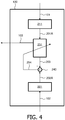
- Fig. 4 shows an alternative embodiment of the device 100 for determining an acoustic coupling 103 comprising an adaptive filter 231.
- the device 100 comprises a first changes-in-envelope determining circuit 211 for determining the first changes of the envelope 201A of the far-end talker signal 101 and a second changes-in-envelope determining circuit 221 for determining the second changes of the envelope 202A of the combined signal 102.
- the device 100 comprises the adaptive filter 231 for filtering an output signal of the first changes-in-envelope determining circuit 211, wherein the adaptive filter 231 is controlled by a residual signal 204.
- One of coefficients of the adaptive filter 231 represents the ratio of changes in the envelope 202A of the combined signal 102 to changes in the changes in the envelope 201A of the far-end talker signal 101 in a predetermined time interval.
- the residual signal 204 is provided by a subtraction circuit 240 that calculates a difference between the output signal of the adaptive filter 231 and the output signal 202A of the second changes-in-envelope determining circuit 221.
- the envelope determining circuits 211 and 221 determine the changes of the envelope of the far-end signal and near-end signal respectively, according to one of the methods described above.
- the adaptive filter 231 adjusts its coefficients in such a way that the energy of the residual signal 204 is minimized.
- a Normalized Least Mean Square (NLMS) filter as described in S. Haykin, Adaptive Filter Theory, Englewood Cliffs (NJ, USA): Prentice-Hall, 1986, ISBN 0-13-004052-5 025 , can be used.
- NLMS filter a Block Frequency Domain Adaptive Filter or a Partitioned Domain Adaptive Filter, as described in G.P.M.
- the adaptive filter 231 is a one-tap filter. After the adaptive filter 231 has converged the estimate of the acoustic coupling 103 is derived as the square of the coefficient of the adaptive filter 231.
- the adaptive filter 231 is a multi-tap filter, wherein the ratio of changes in an envelope 202A of the combined signal 102 to changes in the envelope 201A of the far-end talker signal 101 in a predetermined time interval is determined as a coefficient of the adaptive filter 231 having a largest value.
- a delay between a far-end talker signal (101) and the echo of a far-end talker signal is determined by a location of a tap with a largest value of the adaptive filter (231) that determines the acoustic coupling (103).
- Fig. 5 shows schematically an embodiment of an acoustic echo canceller comprising the device 100 for determining an acoustic coupling according to the invention.
- the acoustic echo canceller comprises the loudspeaker 110 reproducing the far-end talker signal 101, and the microphone 120 picking-up a combined signal 102 comprising an echo of the far-end talker signal 101 and a near-end talker signal.
- the acoustic echo canceller further comprises an echo filter 140, often being realized as an adaptive filter, for predicting an echo on the microphone 120 caused by the loudspeaker 110.
- the echo filter 140 is filtering the far-end talker signal 101 in dependence on a difference 105 between the output signal 104 of the echo filter 140 and the combined signal 102.
- the difference signal 105 is obtained in a further subtraction circuit 150.
- the acoustic echo canceller further comprises the device 100 for determining an acoustic coupling 103 between the loudspeaker 110 and a microphone 120 according to the invention.
- the echo filter 140 is controlled by the acoustic coupling 103.
- a Normalized Least Mean Square (NLMS) algorithm with step-size control can be used for an adaptation of the echo filter 140.
- NLMS Normalized Least Mean Square
- the NLMS algorithm might have the following learning rule (as described in S.
- the samples in the delay line of the N-point transversal filter of the further adaptive filter at (discrete-) time k, w k and w k +1 are the vectors comprising the filter coefficients of the transversal filter at time k and k + 1 respectively, r k is the further residual signal, P xx is the smoothed power of the input signal 101, and ⁇ is the step-size.
- Fig. 6 shows schematically an embodiment of an acoustic echo canceller comprising a delay circuit 160 preceding the echo filter 140 to delay the far-end talker signal 101.
- the delay circuit 160 is controlled by the acoustic coupling 103.
- the functional circuits of the acoustic echo canceller that are in common with the acoustic echo canceller depicted in Fig. 5 are the same for the acoustic echo canceller depicted in Fig. 6 .
- the acoustic coupling determining device 100 comprises e.g. a multi-tap adaptive filter, wherein the location of a tap with the largest value in an impulse response of the multi tap adaptive filter determines the size of the bulk delay. If, for example, the peak is located at a tap n and the predetermined interval is B samples large, the bulk delay is maximally (n-1)*B samples. In practice a somewhat lower value is taken to guarantee that the adaptive filter covers the real acoustic impulse response.
- the above described acoustic echo cancellers can be advantageously applied in webcam devices, video-conferencing systems or hands-free telephone terminals.
Landscapes
- Engineering & Computer Science (AREA)
- Signal Processing (AREA)
- Health & Medical Sciences (AREA)
- General Health & Medical Sciences (AREA)
- Otolaryngology (AREA)
- Physics & Mathematics (AREA)
- Acoustics & Sound (AREA)
- Cable Transmission Systems, Equalization Of Radio And Reduction Of Echo (AREA)
- Telephone Function (AREA)
Description
- The invention relates to a device for determining an acoustic coupling between a far-end talker signal and a combined signal that comprises an echo of the far-end talker signal and a near-end talker signal. The invention also relates to a method for determining an acoustic coupling between a far-end talker signal and a combined signal. Furthermore, the invention relates to an acoustic echo canceller, a webcam device, a video conferencing system, and hands-free telephone terminal.
- In full-duplex hands-free communication system nowadays always Acoustic Echo Cancellers (AECs) are used.
-
FR2674389 -
US2004//057574 discloses the system in which in a microphone signal, the signal component corresponding to, e.g., echo is suppressed using an echo control scheme that estimates the spectral envelope of the echo signal, without having to estimate the waveform for the echo signal. The input signal and the microphone signal are spectrally decomposed into multiple bands, where each suppression processing is independently performed on each subband. -
US6625279 disclosed an echo path delay estimating apparatus and method for estimating the echo path delay using decimators and an adaptive filter, so that a short computation time is used by the echo canceller. -
US2004/062386 discloses an apparatus and method for bulk delay insertion prior to echo cancellation, with echo suppression. -
JP2006279191 JP2006148375 - The adaptive filter, typically implemented as an N-point transversal filter, updates its coefficients by correlating the residual signal, which is a difference between the microphone signal and the replica of the echo signal, with the input data of the transversal filter. However, this works well if only the echo is present. If also the near-end talker signal is present, then problems can occur, since the adaptive filter will diverge due to the presence of the near-end talker signal. If the far-end talker signal and the near-end talker signal are correlated these problems are more severe. A solution to this problem is to reduce the amount of adaptation in case of double talk and in case of severe double talk even to stop the adaptation. A well-known solution is to use step-size control like e.g. given in A. Mader, H. Puder and G.U. Schmidt, "Step-size control for acoustic echo cancellation filters - an overview", Signal processing 80 (2000) pp. 1697-1719.
The updates of coefficients of the adaptive filter are then dependent on the acoustic coupling such that the step-size of the adaptive filter decreases once a near-end speaker becomes active. The acoustic coupling is then estimated as the ratio of powers of the far-end talker signal to the microphone signal. However, for double talk situations this acoustic coupling is estimated too large, such that the decrease in the step-size of the adaptive filter becomes too small and the adaptive filter diverges from its optimum solution. - It is an object of the present invention to provide an improved determination of an acoustic coupling between a far-end talker signal and a combined signal, which results in a better estimate of the acoustic coupling during double talk. The invention is defined by the independent claims. The dependent claims define advantageous embodiments.
- According to the present invention, this object is achieved in that the acoustic coupling is derived from a ratio of changes in an envelope of the combined signal to changes in an envelope of the far-end talker signal in a predetermined time interval. In this way the systematic error during double talk (an estimation of the acoustic coupling that is too large) is not present anymore or at least strongly reduced.
- In a further embodiment, the envelope of the combined signal and the envelope of the far-end talker signal are obtained from the combined signal by rectifying and averaging on a block basis and the far-end talker signal by rectifying and averaging on the block basis, respectively. This method is advantageous for signals with a slow-varying envelope like e.g. speech.
- In a further embodiment, the envelope of the combined signal and the envelope of the far-end talker signal are derived from a power measurement for the combined signal and the far-end talker signal, respectively, on a block basis. This method is advantageous for signals with a slow-varying envelope like e.g. speech, and can be implemented very efficiently on certain DSP platforms.
- In a further embodiment, the predetermined time interval is a time interval between successive samples of the far-end talker signal, wherein sampling of the combined signal is aligned with sampling of the far-end talker signal. The alignment of the sampling of the combined signal with the far-end talker signal is necessary since the echo at the microphone can be considered as a linear convolution of the loudspeaker signal with the acoustic path that is a function of the acoustic coupling.
- In a further embodiment, the predetermined time interval comprises a multiplicity of a time interval between the successive samples of the far-end talker signal, wherein sampling of the combined signal is aligned with sampling of the far-end talker signal. In this way the acoustic coupling can be determined on a block basis (i.e. blocks of samples). This allows to make an update of the acoustic coupling only once per block and thus provides computational reduction.
- In a further embodiment, the device comprises:
- a first changes-in-envelope determining circuit for determining the changes in the envelope of the far-end talker signal,
- a second changes-in-envelope determining circuit for determining the changes in the envelope of the combined signal,
- an adaptive filter for filtering the changes in the envelope of the far-end talker signal, wherein the adaptive filter is controlled by a residual signal, wherein one of coefficients of the adaptive filter is the ratio of the changes in an envelope of the combined signal to the changes in the envelope of the far-end talker signal in the predetermined time interval, and
- a subtraction circuit for determining the residual signal being a difference between the output signal of the adaptive filter and the changes in the envelope of the combined signal. The advantage of using the adaptive filter is that with such a (simple) adaptive filter a robust estimate of the acoustic path can be obtained.
- In a further embodiment, the adaptive filter is a multi-tap filter, wherein the ratio of changes in the envelope of the combined signal to changes in the envelope of the far-end talker signal in the predetermined time interval is determined as a coefficient of the adaptive filter having a largest value.
- In a further embodiment, a delay between a far-end talker signal and the echo of a far-end talker signal is determined by a location of a tap with a largest value of the adaptive filter that determines the acoustic coupling. In this way the bulk delay that is sometimes present in certain applications can be estimated. This is for example the case in digital TV sets, where the audio is delayed in order to be synchronized with a video.
- According to another aspect of the invention there is provided a method for determining an acoustic coupling between a far-end talker signal and a combined signal. It should be appreciated that the features, advantages, comments, etc. described above are equally applicable to this aspect of the invention.
- The invention further provides an acoustic echo canceller, a webcam device, a video-conferencing system, and a hands-free telephone terminal comprising a device according to the invention.
- These and other aspects, features and advantages of the invention will be apparent from and elucidated with reference to the embodiment(s) described hereinafter.
-
-
Fig. 1 shows schematically an embodiment of a device for determining an acoustic coupling according to the invention between a loudspeaker and a microphone; -
Fig. 2 shows a plot that illustrates an effect of deriving an acoustic coupling from a ratio of changes in an envelope of the combined signal to changes in the envelope of the far-end talker signal in a predetermined time interval; -
Fig. 3 shows an example architecture of the device for determining an acoustic coupling according to the invention; -
Fig. 4 shows an alternative embodiment of the device for determining an acoustic coupling comprising an adaptive filter; -
Fig. 5 shows schematically an embodiment of an acoustic echo canceller comprising the device for determining an acoustic coupling according to the invention; -
Fig. 6 shows schematically an embodiment of an acoustic echo canceller comprising a delay circuit preceding the further adaptive filter to delay the far-end talker signal, wherein the delay circuit is controlled by the acoustic coupling. -
Fig. 1 shows schematically an embodiment of adevice 100 for determining anacoustic coupling 103 according to the invention between aloudspeaker 110 and amicrophone 120. Theloudspeaker 110 is reproducing the far-end talker signal 101. Themicrophone 120 is picking-up a combinedsignal 102 comprising an echo of the far-end talker signal 101 and a near-end talker signal. The acoustic coupling phenomenon between theloudspeaker 110 and themicrophone 120 is symbolically depicted by thearrow 130.
Theacoustic coupling 103 is derived from a ratio of changes in an envelope of the combinedsignal 102 to changes in the envelope of the far-end talker signal 101 in a predetermined time interval. The derived acoustic coupling is outputted by thedevice 100 in the form of asignal 103. -
Fig. 2 shows a plot that illustrates an effect of deriving theacoustic coupling 103 from the ratio of the changes in the envelope of the combinedsignal 102 to the changes in the envelope of the far-end talker signal 101 in the predetermined time interval. An x-axis depicts a time in terms of blocks of signal samples. A y-axis depicts the square root of the acoustic coupling. A solid line plot shows the square root of the acoustic coupling, wherein the acoustic coupling is derived as the square root of the ratio of the power of the combinedsignal 102 to the power of the far-end talker signal 101 in the predetermined time interval. A dashed line plot shows the square root of the acoustic coupling, wherein the acoustic coupling is derived as the ratio of the changes in the envelope of the combinedsignal 102 to the changes in the envelope of the far-end talker signal 101 in the predetermined time interval. In the depicted period there is (almost) continuous far-end speech present in the far-end talker signal 101. This period is split into two sub-periods, where a first sub-period is in a range of 1 to 1400 blocks, where each block corresponds to 80 samples, and a second sub-period is in the range 1400 to 4500 blocks. The square root of theacoustic coupling 103 in the first sub-period takes a value of about 0.1, while in the second sub-period takes the value of about 1. There is a double talk in the sub-ranges between 700 and 1200 blocks, between 2100 and 2600 blocks, and between 3400 and 4000 blocks. A level of a near-end speech comprised in the near-end talker signal during the first two sub-periods is about the same as the level of the far-end speech signal comprised in the far-end talker signal whereas during the third sub-period the near-end speech signal comprised in the near-end talker signal is about 20 dB lower than the far-end speech signal. The square root of the acoustic coupling depicted by the solid line is correct only for periods when no double talk is present. For the acoustic coupling determined according to the invention and its square root depicted by the dashed line there is almost no deviation during the double talk in the sub-period between 700 and 1200 blocks, whereas for the sub-periods in the blocks between 2100 and 2600 blocks, and between 3400 and 4000 blocks the deviation is smaller than this exhibited by the solid line plot. Even more importantly, the deviation has an opposite direction. This could in other words be expressed as underestimating of the acoustic coupling in these sub-periods. During the double talk there are two talkers active simultaneously and, especially when they both are equally strong as they are in the sub-period of 2100 to 2600 blocks, the deviation of the envelope of the combinedsignal 102 is smaller than the envelope of the individual components of the echo and the near-end speech. Such underestimating is actually desired as it leads to slower adaptation of the adaptive filter during double talk, which is what we want. -
Fig. 3 shows an example architecture of thedevice 100 for determining anacoustic coupling 103 according to the invention. Thedevice 100 comprises a firstenvelope determining circuit 210 for determining afirst envelope 201 of the far-end talker signal 101 and a secondenvelope determining circuit 220 for determining asecond envelope 202 of the combinedsignal 102. Further, thedevice 100 comprises adifference circuit 230 to which theenvelopes circuits difference circuit 230 determines theacoustic coupling 103, which is derived from a ratio of changes in thefirst envelope 201 to changes in thesecond envelope 202 in a predetermined time interval. - In an embodiment, the envelope of the signal as obtained in the first
envelope determining circuit 210 and the secondenvelope determining circuit 220 is determined by rectifying (i.e. taking the absolute value of the signal) and low-pass filtering thesignals - In a further embodiment, the envelope of the signal as obtained in the first
envelope determining circuit 210 and the secondenvelope determining circuit 220 is obtained from an average rectified combined signal on a block basis and an average rectified far-end talker signal on the block basis, respectively. The size of a block is determined by the (average) change in the speech envelope and is for example 160 samples at a sampling frequency of 16 kHz. For a signal x the envelope xe obtained from the average rectified signal on block basis can be expressed as:
- In a further embodiment, the envelope of the combined
signal 201 and the envelope of the far-end talker signal 202 are derived from a power measurement on a block basis. One ways to calculate the envelope of a signal is to take the square root of the power of the signal on block basis. For a signal x the envelope xe can then be expressed as:
- In a further embodiment, the changes in an envelope are the differences of the envelope at a beginning and at an end of the predetermined time interval. For the signal x the change in the envelope of this signal Δx
e over the time interval delimited by samples (k - D) and k can then be expressed as:
- The time intervals over which the acoustic coupling is determined are adjacent to each other. However, these intervals could also overlap.
- In a further embodiment, the changes in an envelope are estimated by highpass filtering the envelope signal with a zero-DC filter.
- In a further embodiment, the predetermined time interval is the time interval between the successive samples of the far-
end talker signal 101, wherein sampling of the combinedsignal 102 is aligned with the sampling of the far-end talker signal 101. For the signal x the change in the envelope of this signal Δ xe between the successive samples k and (k + 1) can then be expressed as:
- In a further embodiment, the predetermined time interval is the time interval comprising a multiplicity of the time interval between the successive samples of the far-end talker signal, wherein sampling of the combined
signal 102 is aligned with the sampling of the far-end talker signal 101. The size of a block is determined by the (average) change in the speech envelope and is for example 160 samples at a sampling frequency of 16 kHz. For the signal x the change in the envelope of this signal Δ xe can then be expressed as:
-
Fig. 4 shows an alternative embodiment of thedevice 100 for determining anacoustic coupling 103 comprising anadaptive filter 231. Thedevice 100 comprises a first changes-in-envelope determining circuit 211 for determining the first changes of theenvelope 201A of the far-end talker signal 101 and a second changes-in-envelope determining circuit 221 for determining the second changes of theenvelope 202A of the combinedsignal 102. Further, thedevice 100 comprises theadaptive filter 231 for filtering an output signal of the first changes-in-envelope determining circuit 211, wherein theadaptive filter 231 is controlled by aresidual signal 204. One of coefficients of theadaptive filter 231 represents the ratio of changes in theenvelope 202A of the combinedsignal 102 to changes in the changes in theenvelope 201A of the far-end talker signal 101 in a predetermined time interval. Theresidual signal 204 is provided by asubtraction circuit 240 that calculates a difference between the output signal of theadaptive filter 231 and theoutput signal 202A of the second changes-in-envelope determining circuit 221. - The
envelope determining circuits - The
adaptive filter 231 adjusts its coefficients in such a way that the energy of theresidual signal 204 is minimized. For the adaptation of the filter a Normalized Least Mean Square (NLMS) filter, as described in S. Haykin, Adaptive Filter Theory, Englewood Cliffs (NJ, USA): Prentice-Hall, 1986, ISBN 0-13-004052-5 025, can be used. Alternatively, instead of the NLMS filter a Block Frequency Domain Adaptive Filter or a Partitioned Domain Adaptive Filter, as described in G.P.M. Egelmeers, Real time realization concepts of large adaptive filters, PhD thesis, Eindhoven University of Technology, Eindhoven, The Netherlands, Eindhoven 1995, ISBN 90-386-0456-4, can be used, which means that NLMS algorithm is applied per frequency bin. The adaptation speed of the NLMS filter depends on the spectral shape of the input power. The Block Frequency Domain Adaptive Filter or the Partitioned Domain Adaptive Filter are much less sensitive to the spectral shape of the input power. - In a further embodiment, the
adaptive filter 231 is a one-tap filter. After theadaptive filter 231 has converged the estimate of theacoustic coupling 103 is derived as the square of the coefficient of theadaptive filter 231. - In a further embodiment, the
adaptive filter 231 is a multi-tap filter, wherein the ratio of changes in anenvelope 202A of the combinedsignal 102 to changes in theenvelope 201A of the far-end talker signal 101 in a predetermined time interval is determined as a coefficient of theadaptive filter 231 having a largest value. - In a further embodiment, a delay between a far-end talker signal (101) and the echo of a far-end talker signal is determined by a location of a tap with a largest value of the adaptive filter (231) that determines the acoustic coupling (103).
-
Fig. 5 shows schematically an embodiment of an acoustic echo canceller comprising thedevice 100 for determining an acoustic coupling according to the invention. The acoustic echo canceller comprises theloudspeaker 110 reproducing the far-end talker signal 101, and themicrophone 120 picking-up a combinedsignal 102 comprising an echo of the far-end talker signal 101 and a near-end talker signal. The acoustic echo canceller further comprises anecho filter 140, often being realized as an adaptive filter, for predicting an echo on themicrophone 120 caused by theloudspeaker 110. Theecho filter 140 is filtering the far-end talker signal 101 in dependence on adifference 105 between theoutput signal 104 of theecho filter 140 and the combinedsignal 102. Thedifference signal 105 is obtained in afurther subtraction circuit 150. The acoustic echo canceller further comprises thedevice 100 for determining anacoustic coupling 103 between theloudspeaker 110 and amicrophone 120 according to the invention. Theecho filter 140 is controlled by theacoustic coupling 103. For an adaptation of theecho filter 140, for example, a Normalized Least Mean Square (NLMS) algorithm with step-size control can be used. For example the NLMS algorithm might have the following learning rule (as described in S. Haykin, Adaptive Filter Theory, Englewood Cliffs (NJ, USA): Prentice-Hall, 1986, ISBN 0-13-004052-5 025):
x k is the input vector (i.e. the samples in the delay line of the N-point transversal filter of the further adaptive filter at (discrete-) time k,w k andw k+1 are the vectors comprising the filter coefficients of the transversal filter at time k and k+1 respectively, rk is the further residual signal, Pxx is the smoothed power of theinput signal 101, and α is the step-size. Applying step-size control leads, for example, to the following learning rule:
acoustic coupling 103 and Prr is the smoothed power of the further residual signal. If only far-end talker signal 101 is present, the maximum is determined by Pxx and therefore the echo filter is converging fast. If double talk is present, yPrr is larger than Pxx and the adaptation speed of the echo filter is decreased. -
Fig. 6 shows schematically an embodiment of an acoustic echo canceller comprising adelay circuit 160 preceding theecho filter 140 to delay the far-end talker signal 101. Thedelay circuit 160 is controlled by theacoustic coupling 103. The functional circuits of the acoustic echo canceller that are in common with the acoustic echo canceller depicted inFig. 5 are the same for the acoustic echo canceller depicted inFig. 6 . - The acoustic
coupling determining device 100 comprises e.g. a multi-tap adaptive filter, wherein the location of a tap with the largest value in an impulse response of the multi tap adaptive filter determines the size of the bulk delay. If, for example, the peak is located at a tap n and the predetermined interval is B samples large, the bulk delay is maximally (n-1)*B samples. In practice a somewhat lower value is taken to guarantee that the adaptive filter covers the real acoustic impulse response. - The above described acoustic echo cancellers can be advantageously applied in webcam devices, video-conferencing systems or hands-free telephone terminals.
- Although the present invention has been described in connection with some embodiments, it is not intended to be limited to the specific form set forth herein. Rather, the scope of the present invention is limited only by the accompanying claims. Additionally, although a feature may appear to be described in connection with particular embodiments, one skilled in the art would recognize that various features of the described embodiments may be combined in accordance with the invention. In the claims, the term comprising does not exclude the presence of other elements or steps.
- Furthermore, although individually listed, a plurality of circuits, elements or method steps may be implemented by e.g. a single unit or processor. Additionally, although individual features may be included in different claims, these may possibly be advantageously combined, and the inclusion in different claims does not imply that a combination of features is not feasible and/or advantageous. The word "comprising" does not exclude the presence of elements or steps other than those listed in a claim. Also the inclusion of a feature in one category of claims does not imply a limitation to this category but rather indicates that the feature is equally applicable to other claim categories as appropriate. In addition, singular references do not exclude a plurality. Thus references to "a", "an", "first", "second" etc. do not preclude a plurality. Reference signs in the claims are provided merely as a clarifying example and shall not be construed as limiting the scope of the claims in any way. The invention can be implemented by circuit of hardware comprising several distinct elements, and by circuit of a suitably programmed computer or other programmable device.
Claims (14)
- A device (100) for determining an acoustic coupling (103) between a far-end talker signal (101) and a combined signal (102) that comprises an echo of the far-end talker signal and a near-end talker signal, characterized in that the device (100) comprises circuitry for deriving the acoustic coupling (103) from a ratio of changes in an envelope (202) of the combined signal (102) to changes in the envelope (201) of the far-end talker signal (101) in a predetermined time interval.
- A device as claimed in claim 1, wherein the device comprises means for obtaining the envelope (202) of the combined signal (102) and the envelope (201) of the far-end talker signal (101) from the combined signal (102) by rectifying and averaging on a block basis and from the far-end talker signal (101) by rectifying and averaging on the block basis, respectively.
- A device as claimed in claim 1, wherein the device comprises means for deriving the envelope (202) of the combined signal (102) and the envelope (201) of the far-end talker signal (101) from a power measurement for the combined signal (102) and the far-end talker signal (101), respectively, on a block basis.
- A device as claimed in claim 1, wherein the predetermined time interval is a time interval between successive samples of the far-end talker signal (101), wherein the device comprises means for aligning sampling of the combined signal (102) with sampling of the far-end talker signal (101).
- A device as claimed in claim 1, wherein the predetermined time interval comprises a multiplicity of a time interval between successive samples of the far-end talker signal (101), wherein the device comprises means for aligning sampling of the combined signal (102) with sampling of the far-end talker signal (101).
- A device as claimed in claim 1, wherein the device comprises:- a first changes-in-envelope determining circuit (211) for determining the changes (201A) in the envelope of the far-end talker signal (101),- a second changes-in-envelope determining circuit (221) for determining the changes (202A) in the envelope of the combined signal (102),- an adaptive filter (231) for filtering the changes (201A) in the envelope of the far-end talker signal (101), wherein the adaptive filter (231) is controlled by a residual signal (204), wherein one of coefficients of the adaptive filter (231) is the ratio of the changes (202A) in the envelope of the combined signal (102) to the changes (201A) in the envelope of the far-end talker signal (101) in the predetermined time interval, and- a subtraction circuit (240) for determining the residual signal (204) being a difference between an output signal (203) of the adaptive filter (231) and the changes (202A) in the envelope of the combined signal (102).
- A device as claimed in claim 6, wherein the adaptive filter (231) is a multi-tap filter, wherein the circuitry comprises means for determining the ratio of the changes (202A) in the envelope of the combined signal (102) to the changes in the envelope (201A) of the far-end talker signal (101) in the predetermined time interval as a coefficient of the adaptive filter (231) having a largest value.
- A device as claimed in claim 7, wherein the device comprises means for determining a delay between the far-end talker signal (101) and the echo of the far-end talker signal by a location of the coefficient with the largest value of the adaptive filter (231) that determines the acoustic coupling (103).
- A method by a device for determining an acoustic coupling between a far-end talker signal (101) and a combined signal (102) that comprises an echo of the far-end talker signal and a near-end talker signal, characterized in that the acoustic coupling (103) is derived from a ratio of changes in an envelope (202) of the combined signal (102) to changes in the envelope (201) of the far-end talker signal (101) in a predetermined time interval.
- An acoustic echo canceller comprising:- a loudspeaker (110) for reproducing a far-end talker signal (101),- a microphone (120) for picking-up a combined signal (102) that comprises an echo of the far-end talker signal and a near-end talker signal,- an echo filter (140) for filtering the far-end talker signal in dependence on a difference (105) between the output signal of the echo filter (104) and the combined signal (102) to predict the echo on the microphone (120) caused by the loudspeaker (110), and- a device (100) for determining an acoustic coupling (103) between the far-end talker signal (101) and the combined signal (102) as claimed in any of claims 1-7,wherein the echo filter (140) is further controlled by the acoustic coupling (103).
- An acoustic echo canceller comprising:- a loudspeaker (110) for reproducing a far-end talker signal (101),- a microphone (120) for picking-up a combined signal (102) that comprises an echo of the far-end talker signal and a near-end talker signal,- an echo filter (140) for filtering a delayed far-end talker signal (101) in dependence on a difference (105) between the output signal (104) of the echo filter (140) and the combined signal (102) to predict the echo on the microphone (120) caused by the loudspeaker (110),- a delay circuit (160) preceding the echo filter (140) to delay the far-end talker signal (101), and- a device (100) for determining an acoustic coupling (103) between the far-end talker signal (101) and the combined signal (102) as claimed in claim 7 or 8, wherein the delay circuit (160) is controlled by the location of the coefficient with the largest value of the adaptive filter (231) that determines the acoustic coupling (103).
- A webcam device comprising the acoustic echo canceller according to claims 10 or 11.
- A video-conferencing system comprising the acoustic echo canceller according to claims 10 or 11.
- A hands-free telephone terminal comprising the acoustic echo canceller according to claims 10 or 11.
Priority Applications (1)
| Application Number | Priority Date | Filing Date | Title |
|---|---|---|---|
| EP09795817.7A EP2380339B1 (en) | 2008-12-22 | 2009-12-15 | Determining an acoustic coupling between a far-end talker signal and a combined signal |
Applications Claiming Priority (3)
| Application Number | Priority Date | Filing Date | Title |
|---|---|---|---|
| EP08172546 | 2008-12-22 | ||
| EP09795817.7A EP2380339B1 (en) | 2008-12-22 | 2009-12-15 | Determining an acoustic coupling between a far-end talker signal and a combined signal |
| PCT/IB2009/055755 WO2010073181A1 (en) | 2008-12-22 | 2009-12-15 | Determining an acoustic coupling between a far-end talker signal and a combined signal |
Publications (2)
| Publication Number | Publication Date |
|---|---|
| EP2380339A1 EP2380339A1 (en) | 2011-10-26 |
| EP2380339B1 true EP2380339B1 (en) | 2018-08-15 |
Family
ID=41698240
Family Applications (1)
| Application Number | Title | Priority Date | Filing Date |
|---|---|---|---|
| EP09795817.7A Active EP2380339B1 (en) | 2008-12-22 | 2009-12-15 | Determining an acoustic coupling between a far-end talker signal and a combined signal |
Country Status (7)
| Country | Link |
|---|---|
| US (1) | US9225842B2 (en) |
| EP (1) | EP2380339B1 (en) |
| JP (1) | JP5932337B2 (en) |
| KR (1) | KR101611602B1 (en) |
| CN (1) | CN102265589B (en) |
| TR (1) | TR201815047T4 (en) |
| WO (1) | WO2010073181A1 (en) |
Families Citing this family (7)
| Publication number | Priority date | Publication date | Assignee | Title |
|---|---|---|---|---|
| KR101975251B1 (en) | 2012-07-09 | 2019-05-07 | 삼성전자주식회사 | Audio signal processing system and Method for removing echo signal thereof |
| US20140170991A1 (en) * | 2012-12-18 | 2014-06-19 | Qualcomm Incorporated | Agile active interference cancellation (aaic) for multi-radio mobile devices |
| KR20170032603A (en) | 2015-09-15 | 2017-03-23 | 삼성전자주식회사 | Electric device, acoustic echo cancelling method of thereof and non-transitory computer readable recording medium |
| WO2019026261A1 (en) * | 2017-08-03 | 2019-02-07 | ヤマハ株式会社 | Performance evaluation device and performance evaluation method |
| US10937409B2 (en) * | 2018-11-08 | 2021-03-02 | Knowles Electronics, Llc | Predictive acoustic echo cancellation |
| KR102848942B1 (en) * | 2021-02-01 | 2025-08-21 | 삼성전자주식회사 | Method for processing audio data and electronic device supporting the same |
| CN114584902B (en) * | 2022-03-17 | 2023-05-16 | 睿云联(厦门)网络通讯技术有限公司 | Method and device for eliminating nonlinear echo of intercom equipment based on volume control |
Citations (14)
| Publication number | Priority date | Publication date | Assignee | Title |
|---|---|---|---|---|
| FR2674389A1 (en) | 1991-03-20 | 1992-09-25 | France Telecom | DEVICE FOR ENHANCING THE CONVERGENCE OF AN ECHO CANCER OF A DIGITAL SPEECH SIGNAL. |
| US6126608A (en) | 1999-05-18 | 2000-10-03 | Pie Medical Equipment B.V. | Portable ultrasound diagnostic system with handsfree display |
| US6160886A (en) | 1996-12-31 | 2000-12-12 | Ericsson Inc. | Methods and apparatus for improved echo suppression in communications systems |
| US20020169602A1 (en) | 2001-05-09 | 2002-11-14 | Octiv, Inc. | Echo suppression and speech detection techniques for telephony applications |
| US6556682B1 (en) | 1997-04-16 | 2003-04-29 | France Telecom | Method for cancelling multi-channel acoustic echo and multi-channel acoustic echo canceller |
| US6625279B1 (en) | 1999-07-19 | 2003-09-23 | Samsung Electronics Co., Ltd. | Apparatus and method of estimating echo path delay |
| US20040057574A1 (en) | 2002-09-20 | 2004-03-25 | Christof Faller | Suppression of echo signals and the like |
| US20040062386A1 (en) * | 2002-10-01 | 2004-04-01 | Mansour Tahernezhaadi | Delay insertion for echo cancellation, with echo supression, in a communication network |
| US20040091099A1 (en) | 2002-11-12 | 2004-05-13 | Oki Electric Industry Co., Ltd. | Anti-howling circuit detecting howling from effect of predicted echo signal |
| US20040247111A1 (en) | 2003-01-31 | 2004-12-09 | Mirjana Popovic | Echo cancellation/suppression and double-talk detection in communication paths |
| US20070116300A1 (en) | 2004-12-22 | 2007-05-24 | Broadcom Corporation | Channel decoding for wireless telephones with multiple microphones and multiple description transmission |
| US7450528B1 (en) | 2004-02-17 | 2008-11-11 | Dialogic Corporation | Method and apparatus for performing echo suppression |
| US8116459B2 (en) | 2006-03-28 | 2012-02-14 | Fraunhofer-Gesellschaft Zur Foerderung Der Angewandten Forschung E.V. | Enhanced method for signal shaping in multi-channel audio reconstruction |
| US8311234B2 (en) | 2006-11-10 | 2012-11-13 | Sony Corporation | Echo canceller and communication audio processing apparatus |
Family Cites Families (15)
| Publication number | Priority date | Publication date | Assignee | Title |
|---|---|---|---|---|
| JPH0255687A (en) | 1988-08-19 | 1990-02-26 | Tanaka Kikinzoku Kogyo Kk | Welding method for silver member |
| JPH08256089A (en) | 1995-03-17 | 1996-10-01 | Toshiba Corp | Echo canceller |
| JP3417159B2 (en) * | 1995-08-11 | 2003-06-16 | Kddi株式会社 | Echo canceller device |
| FI106489B (en) | 1996-06-19 | 2001-02-15 | Nokia Networks Oy | Eco-muffler and non-linear processor for an eco extinguisher |
| DE19831320A1 (en) * | 1998-07-13 | 2000-01-27 | Ericsson Telefon Ab L M | Digital adaptive filter for communications system, e.g. hands free communications in vehicles, has power estimation unit recursively smoothing increasing and decreasing input power asymmetrically |
| US6269161B1 (en) * | 1999-05-20 | 2001-07-31 | Signalworks, Inc. | System and method for near-end talker detection by spectrum analysis |
| US7310425B1 (en) | 1999-12-28 | 2007-12-18 | Agere Systems Inc. | Multi-channel frequency-domain adaptive filter method and apparatus |
| JP2003535510A (en) * | 2000-05-26 | 2003-11-25 | コーニンクレッカ フィリップス エレクトロニクス エヌ ヴィ | Method and apparatus for voice echo cancellation combined with adaptive beamforming |
| US6784744B2 (en) * | 2001-09-27 | 2004-08-31 | Powerq Technologies, Inc. | Amplifier circuits and methods |
| JP3979169B2 (en) | 2002-04-26 | 2007-09-19 | 松下電工株式会社 | Echo canceller |
| US7386120B2 (en) | 2004-04-30 | 2008-06-10 | Lsi Corporation | Echo canceller having a frequency domain active region location estimator |
| JP4543896B2 (en) * | 2004-11-18 | 2010-09-15 | 沖電気工業株式会社 | Echo cancellation method, echo canceller, and telephone repeater |
| JP4475155B2 (en) * | 2005-03-28 | 2010-06-09 | 沖電気工業株式会社 | Echo canceller |
| JP4814329B2 (en) | 2005-10-21 | 2011-11-16 | コーニンクレッカ フィリップス エレクトロニクス エヌ ヴィ | Acoustic echo canceller |
| TW200845718A (en) * | 2007-03-09 | 2008-11-16 | Fortemedia Inc | Method and apparatus for echo cancellation |
-
2009
- 2009-12-15 TR TR2018/15047T patent/TR201815047T4/en unknown
- 2009-12-15 JP JP2011541688A patent/JP5932337B2/en active Active
- 2009-12-15 US US13/141,114 patent/US9225842B2/en active Active
- 2009-12-15 CN CN200980151979.XA patent/CN102265589B/en not_active Expired - Fee Related
- 2009-12-15 WO PCT/IB2009/055755 patent/WO2010073181A1/en not_active Ceased
- 2009-12-15 KR KR1020117016935A patent/KR101611602B1/en active Active
- 2009-12-15 EP EP09795817.7A patent/EP2380339B1/en active Active
Patent Citations (14)
| Publication number | Priority date | Publication date | Assignee | Title |
|---|---|---|---|---|
| FR2674389A1 (en) | 1991-03-20 | 1992-09-25 | France Telecom | DEVICE FOR ENHANCING THE CONVERGENCE OF AN ECHO CANCER OF A DIGITAL SPEECH SIGNAL. |
| US6160886A (en) | 1996-12-31 | 2000-12-12 | Ericsson Inc. | Methods and apparatus for improved echo suppression in communications systems |
| US6556682B1 (en) | 1997-04-16 | 2003-04-29 | France Telecom | Method for cancelling multi-channel acoustic echo and multi-channel acoustic echo canceller |
| US6126608A (en) | 1999-05-18 | 2000-10-03 | Pie Medical Equipment B.V. | Portable ultrasound diagnostic system with handsfree display |
| US6625279B1 (en) | 1999-07-19 | 2003-09-23 | Samsung Electronics Co., Ltd. | Apparatus and method of estimating echo path delay |
| US20020169602A1 (en) | 2001-05-09 | 2002-11-14 | Octiv, Inc. | Echo suppression and speech detection techniques for telephony applications |
| US20040057574A1 (en) | 2002-09-20 | 2004-03-25 | Christof Faller | Suppression of echo signals and the like |
| US20040062386A1 (en) * | 2002-10-01 | 2004-04-01 | Mansour Tahernezhaadi | Delay insertion for echo cancellation, with echo supression, in a communication network |
| US20040091099A1 (en) | 2002-11-12 | 2004-05-13 | Oki Electric Industry Co., Ltd. | Anti-howling circuit detecting howling from effect of predicted echo signal |
| US20040247111A1 (en) | 2003-01-31 | 2004-12-09 | Mirjana Popovic | Echo cancellation/suppression and double-talk detection in communication paths |
| US7450528B1 (en) | 2004-02-17 | 2008-11-11 | Dialogic Corporation | Method and apparatus for performing echo suppression |
| US20070116300A1 (en) | 2004-12-22 | 2007-05-24 | Broadcom Corporation | Channel decoding for wireless telephones with multiple microphones and multiple description transmission |
| US8116459B2 (en) | 2006-03-28 | 2012-02-14 | Fraunhofer-Gesellschaft Zur Foerderung Der Angewandten Forschung E.V. | Enhanced method for signal shaping in multi-channel audio reconstruction |
| US8311234B2 (en) | 2006-11-10 | 2012-11-13 | Sony Corporation | Echo canceller and communication audio processing apparatus |
Non-Patent Citations (1)
| Title |
|---|
| GRZEGORZ SZWOCH ET AL.: "A low complexity double-talk detector based on the signal envelope", SIGNAL PROCESSING, vol. 88, no. 11, November 2008 (2008-11-01), pages 2856 - 2862, XP023180368, DOI: 10.1016/j.sigpro.2008.05.013 |
Also Published As
| Publication number | Publication date |
|---|---|
| WO2010073181A1 (en) | 2010-07-01 |
| US20110255703A1 (en) | 2011-10-20 |
| KR20110102474A (en) | 2011-09-16 |
| TR201815047T4 (en) | 2018-11-21 |
| US9225842B2 (en) | 2015-12-29 |
| KR101611602B1 (en) | 2016-04-26 |
| EP2380339A1 (en) | 2011-10-26 |
| CN102265589B (en) | 2014-11-26 |
| JP2012513699A (en) | 2012-06-14 |
| JP5932337B2 (en) | 2016-06-08 |
| CN102265589A (en) | 2011-11-30 |
Similar Documents
| Publication | Publication Date | Title |
|---|---|---|
| US10244121B2 (en) | Automatic tuning of a gain controller | |
| EP2380339B1 (en) | Determining an acoustic coupling between a far-end talker signal and a combined signal | |
| KR101017766B1 (en) | Spectral Domain Nonlinear Echo Cancellation in Hand-Free Devices | |
| CN108141502B (en) | Method for reducing acoustic feedback in an acoustic system and audio signal processing device | |
| JP2538176B2 (en) | Eco-control device | |
| US6928160B2 (en) | Estimating bulk delay in a telephone system | |
| EP1942582B1 (en) | Echo suppressing method and device | |
| US20120063609A1 (en) | Acoustic multi-channel cancellation | |
| US8116448B2 (en) | Acoustic echo canceler | |
| US6532289B1 (en) | Method and device for echo suppression | |
| EP2059014B1 (en) | Echo canceller and echo cancelling program | |
| JPWO2006049260A1 (en) | Signal processing method, signal processing apparatus, and signal processing program | |
| US6381224B1 (en) | Method and apparatus for controlling a full-duplex communication system | |
| US6577731B1 (en) | Method and apparatus of cancelling multi-channel echoes | |
| JP2002057606A (en) | Error-resistant application filter used for cancellation of acoustic and network echo | |
| KR100545832B1 (en) | Sound echo canceller robust to interference signals | |
| CA2266277C (en) | Method and apparatus for echo control in a communication system | |
| US7386120B2 (en) | Echo canceller having a frequency domain active region location estimator | |
| KR100431965B1 (en) | Apparatus and method for removing echo-audio signal using time-varying algorithm with time-varying step size | |
| KR101009867B1 (en) | Echo Canceller and Method for Communication Terminals | |
| JPH07226700A (en) | Echo canceller | |
| JPS6251528B2 (en) | ||
| CN119366116A (en) | Echo suppression device, echo suppression method and echo suppression program | |
| JPH07226699A (en) | Echo canceller | |
| JPH04127721A (en) | Acoustic echo canceler |
Legal Events
| Date | Code | Title | Description |
|---|---|---|---|
| PUAI | Public reference made under article 153(3) epc to a published international application that has entered the european phase |
Free format text: ORIGINAL CODE: 0009012 |
|
| 17P | Request for examination filed |
Effective date: 20110722 |
|
| AK | Designated contracting states |
Kind code of ref document: A1 Designated state(s): AT BE BG CH CY CZ DE DK EE ES FI FR GB GR HR HU IE IS IT LI LT LU LV MC MK MT NL NO PL PT RO SE SI SK SM TR |
|
| DAX | Request for extension of the european patent (deleted) | ||
| RAP1 | Party data changed (applicant data changed or rights of an application transferred) |
Owner name: KONINKLIJKE PHILIPS N.V. |
|
| STAA | Information on the status of an ep patent application or granted ep patent |
Free format text: STATUS: EXAMINATION IS IN PROGRESS |
|
| 17Q | First examination report despatched |
Effective date: 20170626 |
|
| GRAP | Despatch of communication of intention to grant a patent |
Free format text: ORIGINAL CODE: EPIDOSNIGR1 |
|
| STAA | Information on the status of an ep patent application or granted ep patent |
Free format text: STATUS: GRANT OF PATENT IS INTENDED |
|
| INTG | Intention to grant announced |
Effective date: 20180309 |
|
| GRAS | Grant fee paid |
Free format text: ORIGINAL CODE: EPIDOSNIGR3 |
|
| GRAA | (expected) grant |
Free format text: ORIGINAL CODE: 0009210 |
|
| STAA | Information on the status of an ep patent application or granted ep patent |
Free format text: STATUS: THE PATENT HAS BEEN GRANTED |
|
| AK | Designated contracting states |
Kind code of ref document: B1 Designated state(s): AT BE BG CH CY CZ DE DK EE ES FI FR GB GR HR HU IE IS IT LI LT LU LV MC MK MT NL NO PL PT RO SE SI SK SM TR |
|
| REG | Reference to a national code |
Ref country code: CH Ref legal event code: EP Ref country code: GB Ref legal event code: FG4D Ref country code: AT Ref legal event code: REF Ref document number: 1031132 Country of ref document: AT Kind code of ref document: T Effective date: 20180815 |
|
| REG | Reference to a national code |
Ref country code: IE Ref legal event code: FG4D |
|
| REG | Reference to a national code |
Ref country code: DE Ref legal event code: R096 Ref document number: 602009053916 Country of ref document: DE |
|
| REG | Reference to a national code |
Ref country code: NL Ref legal event code: MP Effective date: 20180815 |
|
| REG | Reference to a national code |
Ref country code: LT Ref legal event code: MG4D |
|
| REG | Reference to a national code |
Ref country code: AT Ref legal event code: MK05 Ref document number: 1031132 Country of ref document: AT Kind code of ref document: T Effective date: 20180815 |
|
| PG25 | Lapsed in a contracting state [announced via postgrant information from national office to epo] |
Ref country code: BG Free format text: LAPSE BECAUSE OF FAILURE TO SUBMIT A TRANSLATION OF THE DESCRIPTION OR TO PAY THE FEE WITHIN THE PRESCRIBED TIME-LIMIT Effective date: 20181115 Ref country code: NL Free format text: LAPSE BECAUSE OF FAILURE TO SUBMIT A TRANSLATION OF THE DESCRIPTION OR TO PAY THE FEE WITHIN THE PRESCRIBED TIME-LIMIT Effective date: 20180815 Ref country code: LT Free format text: LAPSE BECAUSE OF FAILURE TO SUBMIT A TRANSLATION OF THE DESCRIPTION OR TO PAY THE FEE WITHIN THE PRESCRIBED TIME-LIMIT Effective date: 20180815 Ref country code: AT Free format text: LAPSE BECAUSE OF FAILURE TO SUBMIT A TRANSLATION OF THE DESCRIPTION OR TO PAY THE FEE WITHIN THE PRESCRIBED TIME-LIMIT Effective date: 20180815 Ref country code: SE Free format text: LAPSE BECAUSE OF FAILURE TO SUBMIT A TRANSLATION OF THE DESCRIPTION OR TO PAY THE FEE WITHIN THE PRESCRIBED TIME-LIMIT Effective date: 20180815 Ref country code: IS Free format text: LAPSE BECAUSE OF FAILURE TO SUBMIT A TRANSLATION OF THE DESCRIPTION OR TO PAY THE FEE WITHIN THE PRESCRIBED TIME-LIMIT Effective date: 20181215 Ref country code: FI Free format text: LAPSE BECAUSE OF FAILURE TO SUBMIT A TRANSLATION OF THE DESCRIPTION OR TO PAY THE FEE WITHIN THE PRESCRIBED TIME-LIMIT Effective date: 20180815 Ref country code: NO Free format text: LAPSE BECAUSE OF FAILURE TO SUBMIT A TRANSLATION OF THE DESCRIPTION OR TO PAY THE FEE WITHIN THE PRESCRIBED TIME-LIMIT Effective date: 20181115 Ref country code: GR Free format text: LAPSE BECAUSE OF FAILURE TO SUBMIT A TRANSLATION OF THE DESCRIPTION OR TO PAY THE FEE WITHIN THE PRESCRIBED TIME-LIMIT Effective date: 20181116 |
|
| PG25 | Lapsed in a contracting state [announced via postgrant information from national office to epo] |
Ref country code: HR Free format text: LAPSE BECAUSE OF FAILURE TO SUBMIT A TRANSLATION OF THE DESCRIPTION OR TO PAY THE FEE WITHIN THE PRESCRIBED TIME-LIMIT Effective date: 20180815 Ref country code: ES Free format text: LAPSE BECAUSE OF FAILURE TO SUBMIT A TRANSLATION OF THE DESCRIPTION OR TO PAY THE FEE WITHIN THE PRESCRIBED TIME-LIMIT Effective date: 20180815 Ref country code: LV Free format text: LAPSE BECAUSE OF FAILURE TO SUBMIT A TRANSLATION OF THE DESCRIPTION OR TO PAY THE FEE WITHIN THE PRESCRIBED TIME-LIMIT Effective date: 20180815 |
|
| PG25 | Lapsed in a contracting state [announced via postgrant information from national office to epo] |
Ref country code: CZ Free format text: LAPSE BECAUSE OF FAILURE TO SUBMIT A TRANSLATION OF THE DESCRIPTION OR TO PAY THE FEE WITHIN THE PRESCRIBED TIME-LIMIT Effective date: 20180815 Ref country code: RO Free format text: LAPSE BECAUSE OF FAILURE TO SUBMIT A TRANSLATION OF THE DESCRIPTION OR TO PAY THE FEE WITHIN THE PRESCRIBED TIME-LIMIT Effective date: 20180815 Ref country code: IT Free format text: LAPSE BECAUSE OF FAILURE TO SUBMIT A TRANSLATION OF THE DESCRIPTION OR TO PAY THE FEE WITHIN THE PRESCRIBED TIME-LIMIT Effective date: 20180815 Ref country code: PL Free format text: LAPSE BECAUSE OF FAILURE TO SUBMIT A TRANSLATION OF THE DESCRIPTION OR TO PAY THE FEE WITHIN THE PRESCRIBED TIME-LIMIT Effective date: 20180815 Ref country code: EE Free format text: LAPSE BECAUSE OF FAILURE TO SUBMIT A TRANSLATION OF THE DESCRIPTION OR TO PAY THE FEE WITHIN THE PRESCRIBED TIME-LIMIT Effective date: 20180815 |
|
| REG | Reference to a national code |
Ref country code: DE Ref legal event code: R026 Ref document number: 602009053916 Country of ref document: DE |
|
| PLBI | Opposition filed |
Free format text: ORIGINAL CODE: 0009260 |
|
| PG25 | Lapsed in a contracting state [announced via postgrant information from national office to epo] |
Ref country code: SK Free format text: LAPSE BECAUSE OF FAILURE TO SUBMIT A TRANSLATION OF THE DESCRIPTION OR TO PAY THE FEE WITHIN THE PRESCRIBED TIME-LIMIT Effective date: 20180815 Ref country code: SM Free format text: LAPSE BECAUSE OF FAILURE TO SUBMIT A TRANSLATION OF THE DESCRIPTION OR TO PAY THE FEE WITHIN THE PRESCRIBED TIME-LIMIT Effective date: 20180815 Ref country code: DK Free format text: LAPSE BECAUSE OF FAILURE TO SUBMIT A TRANSLATION OF THE DESCRIPTION OR TO PAY THE FEE WITHIN THE PRESCRIBED TIME-LIMIT Effective date: 20180815 |
|
| 26 | Opposition filed |
Opponent name: MOLNIA, DAVID Effective date: 20190515 |
|
| PLAX | Notice of opposition and request to file observation + time limit sent |
Free format text: ORIGINAL CODE: EPIDOSNOBS2 |
|
| RAP2 | Party data changed (patent owner data changed or rights of a patent transferred) |
Owner name: MEDIATEK INC. |
|
| REG | Reference to a national code |
Ref country code: CH Ref legal event code: PL |
|
| PG25 | Lapsed in a contracting state [announced via postgrant information from national office to epo] |
Ref country code: MC Free format text: LAPSE BECAUSE OF FAILURE TO SUBMIT A TRANSLATION OF THE DESCRIPTION OR TO PAY THE FEE WITHIN THE PRESCRIBED TIME-LIMIT Effective date: 20180815 Ref country code: SI Free format text: LAPSE BECAUSE OF FAILURE TO SUBMIT A TRANSLATION OF THE DESCRIPTION OR TO PAY THE FEE WITHIN THE PRESCRIBED TIME-LIMIT Effective date: 20180815 Ref country code: LU Free format text: LAPSE BECAUSE OF NON-PAYMENT OF DUE FEES Effective date: 20181215 |
|
| REG | Reference to a national code |
Ref country code: IE Ref legal event code: MM4A |
|
| REG | Reference to a national code |
Ref country code: BE Ref legal event code: MM Effective date: 20181231 |
|
| REG | Reference to a national code |
Ref country code: DE Ref legal event code: R081 Ref document number: 602009053916 Country of ref document: DE Owner name: MEDIATEK INC., TW Free format text: FORMER OWNER: KONINKLIJKE PHILIPS N.V., EINDHOVEN, NL |
|
| PG25 | Lapsed in a contracting state [announced via postgrant information from national office to epo] |
Ref country code: IE Free format text: LAPSE BECAUSE OF NON-PAYMENT OF DUE FEES Effective date: 20181215 |
|
| PLBB | Reply of patent proprietor to notice(s) of opposition received |
Free format text: ORIGINAL CODE: EPIDOSNOBS3 |
|
| PG25 | Lapsed in a contracting state [announced via postgrant information from national office to epo] |
Ref country code: BE Free format text: LAPSE BECAUSE OF NON-PAYMENT OF DUE FEES Effective date: 20181231 |
|
| REG | Reference to a national code |
Ref country code: GB Ref legal event code: 732E Free format text: REGISTERED BETWEEN 20191114 AND 20191120 |
|
| PG25 | Lapsed in a contracting state [announced via postgrant information from national office to epo] |
Ref country code: LI Free format text: LAPSE BECAUSE OF NON-PAYMENT OF DUE FEES Effective date: 20181231 Ref country code: CH Free format text: LAPSE BECAUSE OF NON-PAYMENT OF DUE FEES Effective date: 20181231 |
|
| PG25 | Lapsed in a contracting state [announced via postgrant information from national office to epo] |
Ref country code: MT Free format text: LAPSE BECAUSE OF NON-PAYMENT OF DUE FEES Effective date: 20181215 |
|
| PG25 | Lapsed in a contracting state [announced via postgrant information from national office to epo] |
Ref country code: PT Free format text: LAPSE BECAUSE OF FAILURE TO SUBMIT A TRANSLATION OF THE DESCRIPTION OR TO PAY THE FEE WITHIN THE PRESCRIBED TIME-LIMIT Effective date: 20180815 |
|
| PG25 | Lapsed in a contracting state [announced via postgrant information from national office to epo] |
Ref country code: CY Free format text: LAPSE BECAUSE OF FAILURE TO SUBMIT A TRANSLATION OF THE DESCRIPTION OR TO PAY THE FEE WITHIN THE PRESCRIBED TIME-LIMIT Effective date: 20180815 Ref country code: MK Free format text: LAPSE BECAUSE OF NON-PAYMENT OF DUE FEES Effective date: 20180815 Ref country code: HU Free format text: LAPSE BECAUSE OF FAILURE TO SUBMIT A TRANSLATION OF THE DESCRIPTION OR TO PAY THE FEE WITHIN THE PRESCRIBED TIME-LIMIT; INVALID AB INITIO Effective date: 20091215 |
|
| REG | Reference to a national code |
Ref country code: DE Ref legal event code: R100 Ref document number: 602009053916 Country of ref document: DE |
|
| PLCK | Communication despatched that opposition was rejected |
Free format text: ORIGINAL CODE: EPIDOSNREJ1 |
|
| PLBN | Opposition rejected |
Free format text: ORIGINAL CODE: 0009273 |
|
| STAA | Information on the status of an ep patent application or granted ep patent |
Free format text: STATUS: OPPOSITION REJECTED |
|
| 27O | Opposition rejected |
Effective date: 20201021 |
|
| P01 | Opt-out of the competence of the unified patent court (upc) registered |
Effective date: 20230607 |
|
| PGFP | Annual fee paid to national office [announced via postgrant information from national office to epo] |
Ref country code: GB Payment date: 20231227 Year of fee payment: 15 |
|
| PGFP | Annual fee paid to national office [announced via postgrant information from national office to epo] |
Ref country code: TR Payment date: 20231130 Year of fee payment: 15 Ref country code: FR Payment date: 20231227 Year of fee payment: 15 |
|
| PGFP | Annual fee paid to national office [announced via postgrant information from national office to epo] |
Ref country code: DE Payment date: 20231229 Year of fee payment: 15 |
|
| REG | Reference to a national code |
Ref country code: DE Ref legal event code: R119 Ref document number: 602009053916 Country of ref document: DE |
|
| GBPC | Gb: european patent ceased through non-payment of renewal fee |
Effective date: 20241215 |
|
| PG25 | Lapsed in a contracting state [announced via postgrant information from national office to epo] |
Ref country code: DE Free format text: LAPSE BECAUSE OF NON-PAYMENT OF DUE FEES Effective date: 20250701 |
|
| PG25 | Lapsed in a contracting state [announced via postgrant information from national office to epo] |
Ref country code: GB Free format text: LAPSE BECAUSE OF NON-PAYMENT OF DUE FEES Effective date: 20241215 |
|
| PG25 | Lapsed in a contracting state [announced via postgrant information from national office to epo] |
Ref country code: FR Free format text: LAPSE BECAUSE OF NON-PAYMENT OF DUE FEES Effective date: 20241231 |