EP2380287B1 - Methods and systems for conveying scheduling information of overlapping users in an OFDMA MU-MIMO system - Google Patents
Methods and systems for conveying scheduling information of overlapping users in an OFDMA MU-MIMO system Download PDFInfo
- Publication number
- EP2380287B1 EP2380287B1 EP09838000.9A EP09838000A EP2380287B1 EP 2380287 B1 EP2380287 B1 EP 2380287B1 EP 09838000 A EP09838000 A EP 09838000A EP 2380287 B1 EP2380287 B1 EP 2380287B1
- Authority
- EP
- European Patent Office
- Prior art keywords
- user
- dedicated
- assigned
- overlapping
- users
- Prior art date
- Legal status (The legal status is an assumption and is not a legal conclusion. Google has not performed a legal analysis and makes no representation as to the accuracy of the status listed.)
- Active
Links
- 238000000034 method Methods 0.000 title claims description 90
- 239000011159 matrix material Substances 0.000 claims description 26
- 238000012937 correction Methods 0.000 claims description 10
- 229920006934 PMI Polymers 0.000 claims description 9
- 230000009467 reduction Effects 0.000 claims description 9
- 230000007704 transition Effects 0.000 claims description 4
- 230000000875 corresponding effect Effects 0.000 description 36
- 239000013598 vector Substances 0.000 description 30
- 230000005540 biological transmission Effects 0.000 description 14
- 238000010586 diagram Methods 0.000 description 13
- 230000011664 signaling Effects 0.000 description 11
- 238000013461 design Methods 0.000 description 7
- 230000006870 function Effects 0.000 description 6
- 238000013139 quantization Methods 0.000 description 6
- 238000013459 approach Methods 0.000 description 5
- VJYFKVYYMZPMAB-UHFFFAOYSA-N ethoprophos Chemical compound CCCSP(=O)(OCC)SCCC VJYFKVYYMZPMAB-UHFFFAOYSA-N 0.000 description 4
- 238000013507 mapping Methods 0.000 description 4
- 230000000295 complement effect Effects 0.000 description 2
- 230000000593 degrading effect Effects 0.000 description 2
- 230000003287 optical effect Effects 0.000 description 2
- 230000008569 process Effects 0.000 description 2
- 239000004065 semiconductor Substances 0.000 description 2
- 239000000654 additive Substances 0.000 description 1
- 230000000996 additive effect Effects 0.000 description 1
- 230000008859 change Effects 0.000 description 1
- 239000002131 composite material Substances 0.000 description 1
- 238000004590 computer program Methods 0.000 description 1
- 230000002596 correlated effect Effects 0.000 description 1
- 125000004122 cyclic group Chemical group 0.000 description 1
- 238000000354 decomposition reaction Methods 0.000 description 1
- 230000007774 longterm Effects 0.000 description 1
- 238000012986 modification Methods 0.000 description 1
- 230000004048 modification Effects 0.000 description 1
- 238000010606 normalization Methods 0.000 description 1
- 238000005457 optimization Methods 0.000 description 1
- 230000000737 periodic effect Effects 0.000 description 1
- 230000010363 phase shift Effects 0.000 description 1
- 238000012545 processing Methods 0.000 description 1
- 239000007787 solid Substances 0.000 description 1
- 230000002087 whitening effect Effects 0.000 description 1
Images


Classifications
-
- H—ELECTRICITY
- H04—ELECTRIC COMMUNICATION TECHNIQUE
- H04W—WIRELESS COMMUNICATION NETWORKS
- H04W72/00—Local resource management
- H04W72/04—Wireless resource allocation
-
- H—ELECTRICITY
- H04—ELECTRIC COMMUNICATION TECHNIQUE
- H04B—TRANSMISSION
- H04B7/00—Radio transmission systems, i.e. using radiation field
- H04B7/02—Diversity systems; Multi-antenna system, i.e. transmission or reception using multiple antennas
- H04B7/04—Diversity systems; Multi-antenna system, i.e. transmission or reception using multiple antennas using two or more spaced independent antennas
- H04B7/0413—MIMO systems
- H04B7/0452—Multi-user MIMO systems
-
- H—ELECTRICITY
- H04—ELECTRIC COMMUNICATION TECHNIQUE
- H04L—TRANSMISSION OF DIGITAL INFORMATION, e.g. TELEGRAPHIC COMMUNICATION
- H04L1/00—Arrangements for detecting or preventing errors in the information received
- H04L1/0001—Systems modifying transmission characteristics according to link quality, e.g. power backoff
- H04L1/0023—Systems modifying transmission characteristics according to link quality, e.g. power backoff characterised by the signalling
- H04L1/0025—Transmission of mode-switching indication
-
- H—ELECTRICITY
- H04—ELECTRIC COMMUNICATION TECHNIQUE
- H04L—TRANSMISSION OF DIGITAL INFORMATION, e.g. TELEGRAPHIC COMMUNICATION
- H04L1/00—Arrangements for detecting or preventing errors in the information received
- H04L1/20—Arrangements for detecting or preventing errors in the information received using signal quality detector
-
- H—ELECTRICITY
- H04—ELECTRIC COMMUNICATION TECHNIQUE
- H04L—TRANSMISSION OF DIGITAL INFORMATION, e.g. TELEGRAPHIC COMMUNICATION
- H04L25/00—Baseband systems
- H04L25/02—Details ; arrangements for supplying electrical power along data transmission lines
- H04L25/0202—Channel estimation
- H04L25/0204—Channel estimation of multiple channels
-
- H—ELECTRICITY
- H04—ELECTRIC COMMUNICATION TECHNIQUE
- H04L—TRANSMISSION OF DIGITAL INFORMATION, e.g. TELEGRAPHIC COMMUNICATION
- H04L27/00—Modulated-carrier systems
- H04L27/26—Systems using multi-frequency codes
-
- H—ELECTRICITY
- H04—ELECTRIC COMMUNICATION TECHNIQUE
- H04L—TRANSMISSION OF DIGITAL INFORMATION, e.g. TELEGRAPHIC COMMUNICATION
- H04L5/00—Arrangements affording multiple use of the transmission path
- H04L5/0001—Arrangements for dividing the transmission path
- H04L5/0003—Two-dimensional division
- H04L5/0005—Time-frequency
- H04L5/0007—Time-frequency the frequencies being orthogonal, e.g. OFDM(A), DMT
-
- H—ELECTRICITY
- H04—ELECTRIC COMMUNICATION TECHNIQUE
- H04W—WIRELESS COMMUNICATION NETWORKS
- H04W28/00—Network traffic management; Network resource management
- H04W28/02—Traffic management, e.g. flow control or congestion control
- H04W28/04—Error control
-
- H—ELECTRICITY
- H04—ELECTRIC COMMUNICATION TECHNIQUE
- H04W—WIRELESS COMMUNICATION NETWORKS
- H04W52/00—Power management, e.g. TPC [Transmission Power Control], power saving or power classes
- H04W52/04—TPC
- H04W52/30—TPC using constraints in the total amount of available transmission power
- H04W52/34—TPC management, i.e. sharing limited amount of power among users or channels or data types, e.g. cell loading
- H04W52/346—TPC management, i.e. sharing limited amount of power among users or channels or data types, e.g. cell loading distributing total power among users or channels
-
- H—ELECTRICITY
- H04—ELECTRIC COMMUNICATION TECHNIQUE
- H04W—WIRELESS COMMUNICATION NETWORKS
- H04W72/00—Local resource management
- H04W72/04—Wireless resource allocation
- H04W72/044—Wireless resource allocation based on the type of the allocated resource
- H04W72/0446—Resources in time domain, e.g. slots or frames
-
- H—ELECTRICITY
- H04—ELECTRIC COMMUNICATION TECHNIQUE
- H04W—WIRELESS COMMUNICATION NETWORKS
- H04W72/00—Local resource management
- H04W72/12—Wireless traffic scheduling
-
- H—ELECTRICITY
- H04—ELECTRIC COMMUNICATION TECHNIQUE
- H04W—WIRELESS COMMUNICATION NETWORKS
- H04W72/00—Local resource management
- H04W72/20—Control channels or signalling for resource management
- H04W72/23—Control channels or signalling for resource management in the downlink direction of a wireless link, i.e. towards a terminal
-
- H—ELECTRICITY
- H04—ELECTRIC COMMUNICATION TECHNIQUE
- H04B—TRANSMISSION
- H04B7/00—Radio transmission systems, i.e. using radiation field
- H04B7/02—Diversity systems; Multi-antenna system, i.e. transmission or reception using multiple antennas
- H04B7/04—Diversity systems; Multi-antenna system, i.e. transmission or reception using multiple antennas using two or more spaced independent antennas
- H04B7/06—Diversity systems; Multi-antenna system, i.e. transmission or reception using multiple antennas using two or more spaced independent antennas at the transmitting station
- H04B7/0613—Diversity systems; Multi-antenna system, i.e. transmission or reception using multiple antennas using two or more spaced independent antennas at the transmitting station using simultaneous transmission
- H04B7/0615—Diversity systems; Multi-antenna system, i.e. transmission or reception using multiple antennas using two or more spaced independent antennas at the transmitting station using simultaneous transmission of weighted versions of same signal
- H04B7/0619—Diversity systems; Multi-antenna system, i.e. transmission or reception using multiple antennas using two or more spaced independent antennas at the transmitting station using simultaneous transmission of weighted versions of same signal using feedback from receiving side
- H04B7/0636—Feedback format
- H04B7/0639—Using selective indices, e.g. of a codebook, e.g. pre-distortion matrix index [PMI] or for beam selection
-
- H—ELECTRICITY
- H04—ELECTRIC COMMUNICATION TECHNIQUE
- H04B—TRANSMISSION
- H04B7/00—Radio transmission systems, i.e. using radiation field
- H04B7/02—Diversity systems; Multi-antenna system, i.e. transmission or reception using multiple antennas
- H04B7/04—Diversity systems; Multi-antenna system, i.e. transmission or reception using multiple antennas using two or more spaced independent antennas
- H04B7/06—Diversity systems; Multi-antenna system, i.e. transmission or reception using multiple antennas using two or more spaced independent antennas at the transmitting station
- H04B7/0613—Diversity systems; Multi-antenna system, i.e. transmission or reception using multiple antennas using two or more spaced independent antennas at the transmitting station using simultaneous transmission
- H04B7/0615—Diversity systems; Multi-antenna system, i.e. transmission or reception using multiple antennas using two or more spaced independent antennas at the transmitting station using simultaneous transmission of weighted versions of same signal
- H04B7/0619—Diversity systems; Multi-antenna system, i.e. transmission or reception using multiple antennas using two or more spaced independent antennas at the transmitting station using simultaneous transmission of weighted versions of same signal using feedback from receiving side
- H04B7/0658—Feedback reduction
- H04B7/066—Combined feedback for a number of channels, e.g. over several subcarriers like in orthogonal frequency division multiplexing [OFDM]
-
- H—ELECTRICITY
- H04—ELECTRIC COMMUNICATION TECHNIQUE
- H04L—TRANSMISSION OF DIGITAL INFORMATION, e.g. TELEGRAPHIC COMMUNICATION
- H04L1/00—Arrangements for detecting or preventing errors in the information received
- H04L1/0001—Systems modifying transmission characteristics according to link quality, e.g. power backoff
- H04L1/0002—Systems modifying transmission characteristics according to link quality, e.g. power backoff by adapting the transmission rate
- H04L1/0003—Systems modifying transmission characteristics according to link quality, e.g. power backoff by adapting the transmission rate by switching between different modulation schemes
-
- H—ELECTRICITY
- H04—ELECTRIC COMMUNICATION TECHNIQUE
- H04L—TRANSMISSION OF DIGITAL INFORMATION, e.g. TELEGRAPHIC COMMUNICATION
- H04L1/00—Arrangements for detecting or preventing errors in the information received
- H04L1/0001—Systems modifying transmission characteristics according to link quality, e.g. power backoff
- H04L1/0009—Systems modifying transmission characteristics according to link quality, e.g. power backoff by adapting the channel coding
-
- H—ELECTRICITY
- H04—ELECTRIC COMMUNICATION TECHNIQUE
- H04L—TRANSMISSION OF DIGITAL INFORMATION, e.g. TELEGRAPHIC COMMUNICATION
- H04L1/00—Arrangements for detecting or preventing errors in the information received
- H04L1/0001—Systems modifying transmission characteristics according to link quality, e.g. power backoff
- H04L1/0023—Systems modifying transmission characteristics according to link quality, e.g. power backoff characterised by the signalling
- H04L1/0026—Transmission of channel quality indication
-
- H—ELECTRICITY
- H04—ELECTRIC COMMUNICATION TECHNIQUE
- H04W—WIRELESS COMMUNICATION NETWORKS
- H04W72/00—Local resource management
- H04W72/50—Allocation or scheduling criteria for wireless resources
- H04W72/54—Allocation or scheduling criteria for wireless resources based on quality criteria
- H04W72/542—Allocation or scheduling criteria for wireless resources based on quality criteria using measured or perceived quality
-
- H—ELECTRICITY
- H04—ELECTRIC COMMUNICATION TECHNIQUE
- H04W—WIRELESS COMMUNICATION NETWORKS
- H04W8/00—Network data management
- H04W8/26—Network addressing or numbering for mobility support
Definitions
- the present invention relates to orthogonal frequency-division multiplexing based multiple access (OFDMA) multi-user (MU)-multiple input multiple output (MIMO) systems and, more particularly, to the conveyance of scheduling information to MU-MIMO users in such systems.
- OFDMA orthogonal frequency-division multiplexing based multiple access
- MU multi-user
- MIMO multiple input multiple output
- each active user reports a preferred precoder matrix index (PMI), which identifies a specific vector (or matrix) in a code-book of unit norm vectors (or matrices) used to encode signals between the base station and users. Further, each user can report a channel quality index (CQI) to the base station, which, in turn, can use the PMI and CQI to determine an appropriate set of scheduled users and scheduling parameters for each user.
- the base station provides each scheduled user with its scheduling parameters indicating assigned resource blocks that comprise a set of subcarriers and OFDM symbols and that are used to transmit data to the respective scheduled user.
- UEs User equipments
- the classification may be based upon the number of transmit and receive antennas, sector loading, data requirements, long-term channel statistics, the number of UEs, etc.
- PHILIPS "Performance of LTE DL MU-MIMO with dedicated pilots", 3GPP DRAFT; R1-071403, 3RD GENERATION PARTNERSHIP PROJECT (3GPP), MOBILE COMPETENCE CENTRE ; 650, ROUTE DES LUCIOLES ; F-06921 SOPHIA-ANTIPOLIS CEDEX ; FRANCE, vol. RAN WG1, no. St. Julian; 20070403, 3 April 2007 (2007-04-03 ), relates to performance of LTE DL MU-MIMO with dedicated pilots.
- NOKIA ET AL "Finalizing Multi-User MIMO for LTE Rel. 8", 3GPP DRAFT; R1-083093, 3RD GENERATION PARTNERSHIP PROJECT (3GPP), MOBILE COMPETENCE CENTRE ; 650, ROUTE DES LUCIOLES ; F-06921 SOPHIA-ANTIPOLIS CEDEX ; FRANCE, no. Jeju; 20080812,12 August 2008 (2008-08-12 ), relates to multi-user MIMO for LTE Rel. 8.
- MOTOROLA "LTE-A DL-MIMO Enhancements --- 8-Tx eNB and MU-MIMO Optimization", 3GPP DRAFT; R1-084406 DL-MIMO ENHANCEMENT (MOTOROLA), 3RD GENERATION PARTNERSHIP PROJECT (3GPP), MOBILE COMPETENCE CENTRE ; 650, ROUTE DES LUCIOLES ; F-06921 SOPHIA-ANTIPOLIS CEDEX ; FRANCE, no. Prague, Czech Republic; 20081105, 5 November 2008 (2008-11-05 ), relates to LTE-A DL-MIMO Enhancements and discloses that PMI of other UEs are signaled to each UE to enable interference cancellation.
- ERICSSON "Remaining Details on Control Signaling for the MU-MIMO Transmission Mode", 3GPP DRAFT; R1-082464, 3RD GENERATION PARTNERSHIP PROJECT (3GPP), MOBILE COMPETENCE CENTRE ; 650, ROUTE DES LUCIOLES ; F-06921 SOPHIA-ANTIPOLIS CEDEX ; FRANCE, vol. RAN WG1, no. Warsaw, Poland; 20080625, 25 June 2008 (2008-06-25 ), relates to control signaling for the MU-MIMO transmission mode.
- exemplary aspects provide novel methods and systems that convey scheduling information of other co-scheduled users to each user.
- the scheduling information of co-scheduled users can be employed by a user to improve error correction on its received data and reduce interference on its received channels.
- exemplary aspects also provide scheduled MU-MIMO users with a means to accurately estimate the interference it may experience when selecting a preferred PMI and CQI initially transmitted to a base station.
- a method for conveying scheduling information of overlapping co-scheduled MU-MIMO users to a given MU-MIMO user in an OFDMA system includes: generating scheduling information for each of the MU-MIMO users; determining which MU-MIMO users are overlapping users, wherein an overlapping user is assigned at least one resource block (RB) that overlaps with at least one RB assigned to the given user and wherein an RB is a set of subcarriers and OFDM symbols; and transmitting to the given user the scheduling information for the given user and an indication of at least a portion of the scheduling information for at least one overlapping user to permit the given user to perform at least one of error correction on received data or interference reduction on a received signal by employing the indicated scheduling information for at least one overlapping user.
- RB resource block
- a base station for conveying scheduling information of overlapping co-scheduled MU-MIMO users to a given MU-MIMO user in an OFDMA system includes: a controller configured to determined which MU-MIMO users are overlapping users, wherein an overlapping user is assigned at least one RB that is also assigned to the given user, wherein an RB is a set of subcarriers and OFDM symbols, and configured to compile for transmission to the given user scheduling information for the given user and an indication of at least a portion of scheduling information for at least one overlapping user; and a transmitter configured to transmit to the given user the compiled indication and scheduling information for the given user.
- an OFDMA system for conveying scheduling information of overlapping co-scheduled MU-MIMO users includes: a base station configured to generate scheduling information for a plurality of the MU-MIMO users and to transmit to each given MU-MIMO user the scheduling information for the given MU-MIMO user and an indication of at least a portion of the scheduling information for at least one overlapping user, wherein an overlapping user is assigned at least one RB that overlaps with at least one RB assigned to the given user and wherein an RB is a set of subcarriers and OFDM symbols; and the plurality of MU-MIMO users, wherein each given MU-MIMO user is configured to receive corresponding scheduling information and the corresponding indication and is configured to perform at least one of error correction on received data or interference reduction on a received signal by employing the indicated scheduling information for at least one overlapping user and wherein the corresponding scheduling information for the given MU-MIMO user includes precoder matrix indexes that each correspond to a precoder matrix of an identical rank.
- an OFDMA based multi-user (MU)- multiple input multiple output (MIMO) system 100 in which embodiments may be implemented is illustrated.
- MU multi-user
- MIMO multiple input multiple output
- UEs multiple scheduled users
- BS base station
- RB resource blocks
- performance can be improved if a scheduled user is informed of some scheduling parameters of other overlapping co-scheduled users, such as their corresponding precoding matrices, power levels and modulations. For example, as discussed further below, such information permits the user to estimate effective channels, reduce demodulation errors and suppress interference due to transmissions intended for overlapping co-scheduled users.
- informing each user about the scheduling parameters of other overlapping co-scheduled users, in addition to its own parameters also results in an increased signaling overhead.
- signaling design features are described which allow a base-station to efficiently convey the scheduling parameters of some or all of the other overlapping co-scheduled users to each scheduled user, in addition to that user's own scheduling parameters. Further, such features provide the scheduling parameters with only a relatively small increase in the downlink signaling overhead. Moreover, exemplary embodiments increase system throughput as well as average user-throughput.
- a base station 104 can communicate with a scheduled user 102 by employing a data channel 202 and a control channel 204.
- data of all scheduled users may be transmitted over the data channel 202.
- a user can decode its data using the scheduling parameters made accessible to it.
- scheduling parameters of all scheduled users may be transmitted over the control channel 204.
- Each user can access its scheduling parameters along with at least some scheduling parameters of some or all of the overlapping co-scheduled users.
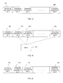
- a schematic 300 of the downlink control channel 204 in which the scheduling parameters of all scheduled users is transmitted is illustrated.
- the scheduling parameters for each respective user, user-1 to user-k may be transmitted in separate blocks 302.
- each scheduled MU-MIMO user can access the part of the control region that includes its scheduling information using its user-ID, as discussed in more detail below.
- each scheduled MU-MIMO user may be informed by the BS about the user IDs of some or all of the other overlapping co-scheduled MU-MIMO users.
- a scheduled MU-MIMO user can access the respective parts of the control region that include the scheduling information for itself and for other users.
- a user-2 401 can access the scheduling parameter information 404 for itself and the scheduling parameter information 406 and 408 for user-3 and user-k, respectively.
- a portion of the scheduling information of some or all of the other overlapping co-scheduled MU-MIMO users can be added to the scheduling information of a scheduled MU-MIMO user to form its extended scheduling information.
- user-1 and user-3 may have scheduling parameters 402, 406 designated for users 1 and 3, respectively, while users 2 and k may have extended scheduling parameters 502 and 504, respectively.
- the extended scheduling parameters can include the scheduling parameters designated for a particular user and at least a portion of the scheduling parameters for some or all of the other overlapping co-scheduled MU-MIMO users.
- the extended scheduling information of some or all scheduled MU-MIMO users may be transmitted in the control channel in each sub-frame and can be accessed by the respective MU-MIMO user via its user ID.
- multiple scheduled users or UEs can be simultaneously served by a base station (BS) on an available set of resource blocks (RBs), where each resource block is a time-frequency resource unit comprising a consecutive set of subcarriers and a consecutive set of OFDM symbols.
- the BS may have one or more transmit antennas and each UE may have multiple receive antennas.
- the BS may use linear transmit precoding to serve each scheduled user.
- the transmit precoder used by the BS and the modulation and coding scheme (MCS) it assigns to each scheduled user may depend on the feedback it receives from the users over the uplink control or data channel.
- MCS modulation and coding scheme
- the BS can configure a user to be a MU-MIMO user in a semi-static manner in which a user, once configured, remains in the MU-MIMO mode for several sub-frames until it is re-configured by the BS.
- the user can decide to be a MU-MIMO user and report its feedback information accordingly.
- a user can explicitly signal its preference to be a MU-MIMO user in its uplink feedback.
- a user can report its feedback information in any format but the BS can decide to schedule it as a MU-MIMO user.
- the user's scheduling information may include a flag or a feature that is unique to the MU-MIMO mode.
- the user Upon accessing its scheduling information, the user can determine that it is in the MU-MIMO mode.
- the feedback procedure in which feedback is received by the base station from each user on the uplink channel can be implemented in a variety of ways.
- Each MU-MIMO user can report or feedback to the BS one precoder matrix index (PMI) per sub-band, which is a set of consecutive RBs, as well as one channel quality index (CQI) per codeword per sub-band.
- PMI precoder matrix index
- CQI channel quality index
- the size of the sub-band as well as the time interval between consecutive UE reports may be configured by the system in a semi-static manner and can be user-specific.
- the PMI determines a particular precoding matrix from a codebook, or a set, of precoding matrices which is known to all users as well as to the BS.
- the uplink channel typically has a finite capacity to accommodate user feedback.
- methods that reduce the feedback from each user without significantly degrading the system performance should be employed.
- the ranks of all precoding matrices reported by a MU-MIMO user can be constrained to be identical.
- the system can also constrain the common rank to correspond to a particular rank, which can be UE specific.
- the common rank can be rank-1.
- the maximum number of codewords that can be transmitted to each user is at-most equal to the rank of the precoding matrices used to serve that user.
- the number of codewords for which the UE computes CQIs may be a function of the rank of its reported PMIs. This function can be pre-determined and identical across all users. In a special case, each user computes and reports only one CQI per sub-band for any rank, wherein this function returns 1 for any input rank.
- the system can constrain each MU-MIMO user to report or feedback to the BS, only one PMI, a wideband PMI, that is identical across all subbands and one CQI per codeword per sub-band.
- the system can also further constrain in a semi-static manner the reported PMI to correspond to a precoding matrix of a particular rank, which can be UE specific, for example, rank-1.
- the system can constrain each MU-MIMO user to report or feedback to the BS only one PMI as well as one CQI per codeword that are identical across all subbands.
- the system can also further constrain the reported PMI in a semi-static manner to correspond to a precoding matrix of a particular rank, which can be UE specific, for example, rank-1.
- the BS can transmit each scheduled user's scheduling information which can include its: RB assignment, assigned modulation constellation per code word, coding rate per codeword, the PMI(s) used and/or the transmit power levels used. It should be understood that the scheduling information for any given user can be different for different subframes.
- the PMIs and the power levels can either be explicitly conveyed as part of the scheduling information or, if user-specific dedicated pilots are employed, they can be implicitly conveyed by informing the user about the positions in which its dedicated pilots are transmitted.
- a dedicated pilot is a pilot, or reference symbol (RS), that is precoded using the precoder used for precoding data transmitted to a particular user and is itself transmitted on one or more subcarriers, OFDM symbol pair in an RB that is assigned to that user.
- a dedicated pilot or RS can be scaled proportionally to the power level used for data transmission, where the proportionality factor can be known to the user.
- the positions, or, equivalently, the OFDM symbol and subcarrier indices, in an RB on which dedicated pilots for a given user are transmitted can be conveyed in the intended user's scheduling information.
- the subband for which each dedicated pilot can be used for channel estimation can be inferred from the user's scheduling information.
- the intended user can then estimate columns of the effective channel matrix after accessing its scheduling information, which, as noted above, may include PMI(s), MCS per codeword and RB assignment.
- the effective channel matrix is the channel matrix multiplied by the precoding matrix, which, as stated above, can be scaled.
- each scheduled user may have the ability to access the part of the control channel including its scheduling information.
- the downlink control channel has a finite capacity to accommodate the scheduling information of all scheduled users.
- the BS may assign only one codeword per subframe to each user in the MU-MIMO mode so that the scheduling information for each user includes only one MCS field per subframe.
- the BS may employ precoders of an identical rank to serve a user in the MU-MIMO mode. Further, in yet another aspect, the BS may employ only one precoder to serve a user in the MU-MIMO mode.
- a scheduled MU-MIMO user can access a part of the scheduling information of some or all of the other overlapping co-scheduled users in addition to its scheduling information.
- An "overlapping co-scheduled user" or “overlapping user” is one whose RB assignment has a non-zero overlap or intersection with that of the user.
- each scheduled user access to at least a part of some or all of the other co-scheduled users' scheduling information permits the user to utilize this information in decoding its own data. For example, if the user is informed of the precoders and power levels that are used to serve some or all of other co-scheduled users, or equivalently if the user is informed of the positions of the dedicated RS (DRS) corresponding to these co-scheduled users on each RB where there is an overlap, the user can estimate the corresponding effective channels and can design minimum mean-square error (MMSE) filters, for each one of its assigned subcarriers, to suppress the interference it encounters due to the transmissions intended for the other co-scheduled users.
- DRS dedicated RS
- the user can employ more sophisticated modulation-aware demodulators which generate more reliable log-likelihood ratios (LLRs) for its codewords and hence reduce its error probability.
- LLRs log-likelihood ratios
- the user can perform interference cancellation by decoding the codewords of some or all of the other co-scheduled users and subtracting the re-constructed codewords.
- aspects of the present invention disclosed herein permit a given user to perform error correction on received data and/or interference reduction on a received signal by employing at least a portion of scheduling information of one or more overlapping users
- the given user need not employ the received portion of scheduling information of overlapping users.
- received portions of scheduling information for overlapping users permit a user to perform error correction and/or interference reduction using the portions of scheduling information
- the user may decide to ignore the portions of scheduling information of overlapping users to reduce complexity and thereby improve its processing speed.
- each scheduled user can access the portion of the control channel including its scheduling information by employing a user-identification (ID) assigned to it.
- ID user-identification
- a scheduled MU-MIMO user can be provided access to all or a part of another overlapping co-scheduled MU-MIMO user's scheduling information.
- a few efficient, exemplary schemes are described herein below.
- the schemes can be classified as multi-access schemes and extended scheduling schemes, which were mentioned above with regard to FIGS. 4 and 5 . It should be noted that, with the exception of the discussion concerning FIGS. 4 and 5 , which distinguish multi-access and extended scheduling schemes, all aspects discussed above can be implemented in either or both the multi-access schemes and extended scheduling schemes.
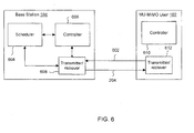
- base station 104 and the MU-MIMO user 102 can be employed to implement multi-access schemes and/or extended scheduling schemes in accordance with exemplary embodiments.
- the user 102 can employ a transmitter/receiver 612 to transmit prccoder matrix index information and channel quality index information to the base station 104 along uplink control channel 602.
- the base station 104 may transmit scheduling information to each MU-MIMO user using a transmitter/receiver 608 along a downlink control channel 204.
- the base station 104 may further include a scheduler 604 and a controller 606 while the user 610 can include controller to implement method embodiments.
- the elements of base station 104 and MU-MIMO user 102 are discussed in more detail below with respect to multi-access schemes and extended scheduling schemes. It should also be noted the functions and configuration of the MU-MIMO user 102 is representative and can be implemented by any one or more or all other MU-MU-MIMO users serviced by the base station. Further, it should be understood that each element depicted in FIG. 6 can be implemented, for example, in entirely hardware or both hardware and software elements.
- each scheduled MU-MIMO user is informed of the user IDs of some or all of the other overlapping co-scheduled MU-MIMO users.
- the user can employ the user IDs to access the respective portions of the control regions that include the scheduling information of the other overlapping co-scheduled MU-MIMO users.
- a schematic of the multi-region access scheme is depicted in FIG. 4 , discussed above.
- Method 700 may begin at optional 702, in which the base station 104 can employ transmitter/receiver 608 to receive preferred precoder matrix index information and/or channel quality index information from each user, as discussed above.
- the scheduler 604 of base station 104 may select an appropriate set of users to schedule and may generate scheduling information for each MU-MIMO user in the set, such as MU-MIMO user 102, as discussed above.
- the controller 606 may determine which of the scheduled MU-MIMO users are overlapping users and may add identifiers that correspond to overlapping users to each user's scheduling information. As stated above, the identifiers can identify different regions of the control channel 204 that include the scheduling information for the overlapping MU-MIMO users.
- the base station 104 can transmit respective scheduling information to each user on the control channel 204 by employing transmitter/receiver 608.
- Method 800 can be performed at any given MU-MIMO user, such as user 102, and can complement method 700.
- the method can begin at optional step 802, in which the controller 610 of user 102 may determine preferred precoder matrix index information and/or channel quality information.
- the MU-MIMO user 102 can employ transmitter/receiver 612 to transmit the preferred precoder and/or channel quality information to the base station 104.
- the user 102 can receive identifiers assigned to different MU-MIMO users. As noted above, the identifiers can identify respective regions of control channel 204 at which different scheduling information for respective MU-MIMO users are located.
- the controller 610 can determine which MU-MIMO users are overlapping users. For example, the controller 610 can determine the overlapping MU-MIMO users by comparing RB assignment fields in the scheduling information for each of the different MU-MIMO users to RB assignment fields in scheduling information for user 102. Thus, a MU-MIMO user is determined to be an overlapping user if it is assigned an RB that is also assigned to user 102.
- the scheduling information for user 102 received from the base station can include identifiers assigned to overlapping users. The controller 610 of user 102 can determine and access the overlapping users' scheduling information by referencing the identifiers assigned to overlapping users in the scheduling information for user 102.
- controller 610 of user 102 can access the overlapping users' scheduling information using the identifiers.
- controller 610 of user 102 can utilize the scheduling information of overlapping users to perform at least one of error correction on received data or interference reduction on received signals, as discussed above.
- the multi-region access scheme can be implemented in a variety of ways using one or more of the following aspects.
- the IDs of some or all of the other overlapping co-scheduled MU-MIMO users can themselves be a part of a scheduled MU-MIMO user's scheduling information.
- the BS in each sub-frame, can transmit or broadcast the IDs of all MU-MIMO users scheduled in that sub-frame in a portion of the control channel reserved for this purpose.
- each MU-MIMO user can thus determine the IDs of all co-scheduled MU-MIMO users.
- Each user can then access their RB assignment fields in its respective scheduling information and determine which co-scheduled MU-MIMO users are overlapping with itself.
- the starting point of this zone or portion of the control channel where the MU-MIMO UE IDs are present may be fixed and may include the number of MU-MIMO users scheduled in that sub-frame. Together, the starting point and the number will determine the size of the zone including the MU-MIMO UE IDs. Further, the starting point can depend on the cell ID and can be conveyed to a user by a base station once it enters the cell.
- the BS can configure a user as a MU-MIMO user in a semi-static manner in that a user remains in the MU-MIMO mode for several sub-frames until it is re-configured by the BS.
- the BS can broadcast or transmit, for example, at step 708 of method 700, the IDs of all users configured in the MU-MIMO mode in a portion of the control channel reserved for this purpose.
- each MU-MIMO user can thus determine the IDs of all other MU-MIMO users.
- the particular sub-frame whose control channel includes the MU-MIMO user IDs can be cell-specific.
- This sub-frame can be transmitted by the base station in a periodic fashion, for example, once every several sub-frames, or in an a-periodic fashion, in which case the users are informed about the transmission of the user-IDs using some other signaling.
- the starting point of the zone or portion of the control channel of the particular sub-frame where all the MU-MIMO UE IDs are present can be fixed and can include the number of users in the MU-MIMO mode. Together, the starting point and the number will determine the size of the zone including the MU-MIMO UE IDs.
- the semi-static case can be implemented slightly differently.
- a user remains in the MU-MIMO mode for several sub-frames until it is re-configured by the BS.
- the BS can transmit or broadcast, for example, at step 708 of method 700, the scheduling information of all scheduled MU-MIMO users in a part of the control channel reserved for this purpose.
- the starting point of this zone or portion of the control channel where the scheduling information of all the scheduled MU-MIMO users is present can be fixed and can include the number of MU-MIMO users scheduled in that sub-frame. Together, the starting point and the number will determine the size of the zone comprising the MU-MIMO scheduling information.
- each MU-MIMO UE can determine the region of the control channel including its own scheduling information using its UE ID and a mapping function specific to the MU-MIMO mode.
- each MU-MIMO UE can first access its scheduling information and then access the scheduling information of all users in the MU-MIMO zone.
- the number of MU-MIMO scheduled in that sub-frame need not be conveyed.
- each scheduled MU-MIMO user's scheduling information can have a special flag unique to the MU-MIMO mode of transmission.
- each MU-MIMO user can first access its scheduling information in the control channel using its UE ID and a mapping function specific to the MU-MIMO mode.
- Each MU-MIMO UE can start accessing the scheduling information of other MU-MIMO UEs beginning from the starting point of the MU-MIMO zone in the control channel.
- Each user can determine that it has reached the end of region of the control channel including the relevant scheduling information when the user encounters scheduling information that belongs to a non MU-MIMO UE.
- exemplary embodiments include employing dedicated reference symbol layers to convey assigned precoder matrix index and power level information, as well as conveying modulation constellations employed by co-scheduled MU-MIMO users.
- Dedicated reference symbol layers are discussed in more detail below with respect to the extended scheduling scheme. However, it should be understood that all features discussed herein below with respect to dedicated reference symbol layers can be implemented in multi-access scheme embodiments as well as other extended scheduling scheme embodiments as understood by those of ordinary skill in the art. For example, indices directed to each user in the extended scheduling scheme conveying the dedicated resource symbol layers and modulation constellations employed by a user can be accessed by other users in the multi-access scheme.
- a given user can access the dedicated reference symbol layers and information about modulation constellations located in the overlapping user's scheduling information.
- the access of scheduling information directed to other users can permit any given user to learn precisely which other users employ which dedicated reference symbol positions and which modulation constellations to improve error correction on received data and/or interference reduction on received signals.
- the details of how dedicated reference symbol layers can be employed to convey precoder matrix index information, power levels and other scheduling information are not repeated here.
- the extended scheduling scheme at least a portion of the scheduling information of some or all of the other overlapping co-scheduled MU-MIMO users is added to the scheduling information of a scheduled MU-MIMO user to form its extended scheduling information.
- a schematic of the downlink control channel is depicted in FIG. 5 , discussed above.
- the extended scheduling information of a scheduled MU-MIMO user may be transmitted in the control channel in each sub-frame and may be accessed by the respective MU-MIMO user via its user ID. Exemplary implementations of an extended scheduling scheme are described herein below.
- Method 900 may begin at optional 902, in which the base station 104 can employ transmitter/receiver 608 to receive preferred precoder matrix index information and/or channel quality index information from each user, as discussed above.
- the scheduler 604 of base station 104 may select an appropriate set of users to schedule and may generate scheduling information for each MU-MIMO user in the set, such as MU-MIMO user 102, as discussed above. Scheduling information generation may comprise allocating or assigning to each MU-MIMO user resource blocks, modulation constellation per codeword, coding rate per codeword, at least one PMI and/or at least one transmit power value. Assignment of resource blocks is discussed in more detail below.
- the controller 606 may determine which of the scheduled MU-MIMO users are overlapping users and may also compile for each scheduled user extended scheduling information.
- the extended scheduling information may include both the scheduling information generated for the given user at step 902 and an indication of at least a portion of the scheduling information for at least one overlapping user.
- the base station 104 can transmit respective extended scheduling information to each user on the control channel 204 by employing transmitter/receiver 608.
- the indication of at least a portion of scheduling information for overlapping users can be employed by the given user to perform at least one of error correction on received data or interference reduction on a received signal.
- Method 1000 can be performed at any given MU-MIMO user; such as user 102, and can complement method 900.
- the method can begin at optional step 1002, in which the controller 610 of user 102 may determine preferred precoder matrix index information, and/or channel quality information.
- the determination of PMI and CQI information at a MU-MIMO user can be performed using one or more methods discussed in more detail below with respect to FIGS. 12-14 .
- the MU-MIMO user 102 can employ transmitter/receiver 612 to transmit the preferred precoder and/or channel quality information to the base station 104.
- the user 102 can determine and process extended scheduling information.
- the extended scheduling information can include both the scheduling information generated for the user 102 and an indication of at least a portion of the scheduling information for at least one overlapping user.
- controller 610 of user 102 can utilize the scheduling information of overlapping users to perform at least one of error correction on received data or interference reduction on received signals, as discussed above. Exemplary features and variations of extended scheduling schemes that can be employed in methods 900 and/or 1000 are described herein below.
- the system can only allow complete overlap among any two overlapping co-scheduled MU-MIMO users.
- any two overlapping co-scheduled MU-MIMO users will be assigned an identical set of RBs.
- each scheduled MU-MIMO user can be served using only one precoder and one MCS per-codeword or only one precoder and one MCS per-codeword per subframe.
- the number of codewords for each user can at-most be equal to the rank of the precoder used to serve that user.
- the (PMI, modulations) pairs of some or all of the other overlapping co-scheduled MU-MIMO users can be a part of each scheduled MU-MIMO user's scheduling information, where each pair corresponds to one overlapping co-scheduled MU-MIMO user.
- the field "modulations" can convey the modulation constellation corresponding to each codeword of the overlapping co-scheduled MU-MIMO user.
- a mapping rule can be employed by the MU-MIMO users to determine the modulation corresponding to each column of the precoder determined by the PMI, for each assigned RB.
- This mapping rule can be pre-determined and identical across all users and can be known to them.
- the field "modulations" can include only one element that corresponds to all columns of the precoder determined by the PMI.
- the system can be constrained to permit only a common modulation constellation for all of its overlapping co-scheduled MU-MIMO users. In this case, the field "modulations" can be dropped.
- the extended scheduling information can, for example, include the information on the positions used for transmitting the dedicated pilots of some or all of the other overlapping co-scheduled MU-MIMO users. It can also include the modulation schemes used to serve some or all of the other overlapping co-scheduled MU-MIMO users. Further, the extended scheduling information signaling design should permit each scheduled MU-MIMO user to determine all the dedicated pilot positions corresponding to at least one other overlapping co-scheduled MU-MIMO user on each of its assigned RBs for which there is an overlap.
- the extended scheduling information can permit the MU-MIMO user to determine if any two known dedicated pilot positions are assigned to the same user or not.
- the extended scheduling information can permit the MU-MIMO user to determine if any two known dedicated pilot positions are assigned to users with the same modulation type and, if so, to determine the modulation constellation type.
- FIGS. 11A and 11B exemplary diagrams of reference blocks 1100 and 1150 having a sum rank of two and four, respectively, are illustrated.
- the configurations of dedicated RS positions, such as positions 1102 and 1152, on each RB can be pre-defined for each choice of the sum rank, which is equivalent to the total number of layers, transmitted on that RB, and can be known to all users and the BS.
- the total number of layers on an RB can be indicative of a corresponding pre-defined configuration of RS layers.
- the dedicated RS positions for each layer in a corresponding pre-defined configuration may be identified by a unique number or index.
- the dedicated RS positions for the first layer can correspond to the blocks labelled "1" while the dedicated RS positions for the second layer can correspond to the blocks labeled "2.”
- the dedicated RS positions for the first, second, third and fourth layers can correspond to the blocks labeled "P1," "P2,” “P3,” and "P4,” respectively.
- the positions of a particular dedicated RS layer in a pre-defined configuration of dedicated RS layers on a given RB can be indicated by an index assigned to the particular dedicated RS layer.
- a scheduled MU-MIMO user's scheduling information can include one or more indices for each of its assigned RBs, along with the total number of layers transmitted on that RB, which together inform the user about its dedicated RS positions.
- all dedicated RS positions corresponding to a layer referred to herein as a dedicated RS layer, may be identified by a unique index.
- a pilot stream is one example of a dedicated RS layer.
- a scheduled MU-MIMO user to which multiple layers are transmitted may only be assigned a set of dedicated RS layers with consecutive indices on each of its allocated RBs. Further, each user that is assigned a particular RB can be assigned a different set of RS layers, wherein the RS layers within a set have consecutive indices. Moreover, the number of layers transmitted to a scheduled MU-MIMO user can be identical across all its assigned RBs and can be the same as the rank of the precoder(s) used to serve it.
- the scheduling information for a particular MU-MIMO user can include the number of its layers and, for each of its allocated RBs, the total number of layers transmitted on that RB and the smallest (first) index among its assigned dedicated RS layers. Accordingly, for each of its allocated RBs, the MU-MIMO user can determine that its dedicated RS positions are simply the smallest (first) index and the next, (n -1) consecutive indexes, where n is the number of its layers for a corresponding RB.
- that user's extended scheduling information may include a field termed "modulations,” which may in turn include the modulation constellations of some or all of the overlapping co-scheduled users.
- modulations may in turn include the modulation constellations of some or all of the overlapping co-scheduled users.
- modulations may in turn include the modulation constellations of some or all of the overlapping co-scheduled users.
- the association of the modulation to the associated DRS layer should be unambiguously conveyed.
- a modulation field having a length equal to the total number of layers assigned to other users can be included, where the leftmost element corresponds to the DRS layer of the smallest index assigned to another user, the second from left element corresponds to the DRS layer of the second smallest index assigned to another user and so on.
- each element of the field can be a ternary digit specifying the three distinct modulations, such as quadrature phase-shift keying (QPSK),16 quadrature (QAM) and 64 QAM, respectively.
- QPSK quadrature phase-shift keying
- QAM 16 quadrature
- 64 QAM 64 QAM
- each element of the field can be a quaternary digit specifying the three distinct modulations, QPSK,16 QAM and 64 QAM, for example, and a modulation not-available option, respectively.
- each scheduled MU-MIMO user can be assigned a set of indices of dedicated RS layers that is common for all of its assigned RBs.
- the set of indices may convey the dedicated RS layers for each of the corresponding user's assigned RB's.
- the assigned dedicated RS layers can also, optionally, be restricted to have consecutive indices, as discussed above.
- the base station can assign the same number of dedicated RS layers to the user for each of the user's assigned RBs such that the indices of the dedicated RS layers assigned to the user are drawn from a common set of consecutive integers.
- each scheduled MU-MIMO user's scheduling information may now include its assigned number of layers and the smallest (first) index among its assigned dedicated RS layers and, for each of its allocated RBs, the total number of layers transmitted on that RB. Accordingly, the assigned number of dedicated RS layers and the smallest index from the set of consecutive integers can be transmitted only once to convey the dedicated RS layers for all of the user's assigned RBs.
- a dedicated RS layer is assigned to some user, then all dedicated RS layers having smaller indices shall also be assigned to one or more users. For example, a case in which each scheduled MU-MIMO user is assigned only consecutively indexed dedicated RS layers on each of its assigned RBs is considered.
- each scheduled MU-MIMO user is assigned only consecutively indexed dedicated RS layers on each of its assigned RBs is considered.
- only the user's assigned number of layers along with the per-RB, total number of layers transmitted and the per-RB, smallest (first) index of the user's assigned dedicated RS layers can be conveyed to adequately inform the user of its dedicated RS positions.
- the user can employ the pre-defined dedicated RS pattern for 4 layers to infer that dedicated RS layers with indices 2 and 3 are for the user, whereas dedicated RS layers indexed 1 and 4 are for the other users. It should be noted that the user can, of course, infer dedicated RS layers as discussed herein in steps 810 and 1006 of methods 800 and 1000, respectfully.
- the smallest index can also be identical across all the assigned RBs, in which case it can be conveyed once (i.e., not repeated) for all the assigned RBs.
- the base-station scheduler can ensure that the same total number of layers are transmitted on all the user's assigned RBs on which there is an overlap.
- each scheduled MU-MIMO user's scheduling information may include this number and a bit for each of its assigned RBs, which can indicate whether there is an overlap or not.
- the base-station scheduler can ensure that the same total number of layers are transmitted on all of the user's assigned RBs.
- each scheduled MU-MIMO user's schduling information can include this number. In either of these two optional cases, each scheduled MU-MIMO user may be assigned only consecutively indexed dedicated RS layers on each of its assigned RBs.
- the smallest (first) index of its assigned dedicated RS layers are sufficient to permit a given user to infer all its dedicated RS layers and those of the other overlapping users on each assigned RB.
- the total number of layers can be transmitted only once for all of the user's assigned RBs.
- the indices of the dedicated RS layers assigned to the user can also be identical across all the user's assigned RBs, in which case the smallest index can be conveyed only once to permit the user to determine its dedicated RS positions.
- signaling may be reduced by accounting for the fact that, from a user's perspective, for each RB, there are three possibilities: not assigned, assigned with no overlap, and assigned with overlap.
- each scheduled MU-MIMO user can be permitted to overlap with the same number of co-scheduled users on each of its assigned RBs for which there is an overlap.
- the same total number of layers are transmitted on all its assigned RBs on which there is an overlap.
- each scheduled MU-MIMO user's scheduling information can include the total number of layers.
- the same number of users or the same total number of dedicated RS layers on any RB assigned to a user the number of users or the total number of dedicated RS layers can be transmitted by the base station in the user's scheduling information only once per subframe to convey the dedicated RS layers for all of the user's assigned RBs.
- the scheduling information can also have a bit for each of its assigned RBs which indicates whether there is an overlap or not. Accordingly, from a user's perspective, for each RB there are three possibilities: not-assigned, assigned-no-overlap and assigned-with-overlap.
- each scheduled MU-MIMO user can be allowed to overlap with the same number of co-scheduled users on all of its assigned RBs. Thus, the same total number of layers are transmitted on all of the scheduled MU-MIMO user assigned RBs.
- each scheduled MU-MIMO user is assigned only consecutively indexed dedicated RS layers on each of its assigned RBs, with the indices of the dedicated layers being common across all assigned RBs, then the number of its layers and the smallest (first) index of its assigned dedicated RS layers are sufficient to permit the user to infer all its dedicated RS layers and those of the other overlapping users on each assigned RB. Accordingly, the number of its layers and the smallest (first) index of its assigned dedicated RS layers can be transmitted only once per sub-frame to indicate all its dedicated RS layers and those of the other overlapping users on all RBs assigned to the user.
- each scheduled MU-MIMO user can be permitted to overlap with the same set of co-scheduled users on each of its assigned RBs for which there is an overlap.
- the same total number of layers are transmitted on all of a scheduled MU-MIMO user's assigned RBs on which there is an overlap.
- Each scheduled MU-MIMO user's scheduling information can include a bit for each of its assigned RBs which indicates whether there is an overlap or not. Further, from a user's perspective, for each RB there are three possibilities: not-assigned, assigned-no-overlap and assigned-with-overlap.
- each scheduled MU-MIMO user can be permitted to overlap with the same set of co-scheduled users on all of its assigned RBs.
- the same total number of layers are transmitted on all of a scheduled user's assigned RBs.
- each scheduled MU-MIMO user is assigned only consecutively indexed dedicated RS layers on each of its assigned RBs, with the indices of the dedicated RS layers being common across all its assigned RBs, then the number of its layers and the smallest (first) index of its assigned dedicated RS layers are sufficient to permit the scheduled MU-MIMO user to infer all its dedicated RS layers and those of the other overlapping users on each assigned RB.
- the modulation(s) corresponding to some or all of the overlapping users can be conveyed once in its extended scheduling information, irrespective of the number of its overlapping assigned RBs.
- UAF user association field
- the UAF length can be 4 bits.
- the UAF has a bit for each of these four layers with the first, leftmost bit corresponding to the layer with the smallest index, 1 in this case, and can always be 1.
- the last, rightmost bit corresponds to the layer with the largest index, 6 in this case.
- a transition from 1-to-0 or 0-to-1 can imply a change in the assigned user.
- 1110 implies that the layers 1, 2 and 5 are assigned to a particular user and that the layer 6 is assigned to another user.
- 1010 implies that the layers 1, 2, 5 and 6 are all assigned to distinct users.
- the association of dedicated RS layers to modulations can also be conveyed via a modulation association field (MAF), which can be implemented as a string of ternary digits.
- MAF modulation association field
- the MAF length can be 4 digits.
- dedicated RS layers with indices 1,2,5,6 correspond to the other users.
- the MAF can have a ternary digit for each one of these four layer with the first, leftmost digit corresponding to the layer with the smallest index, 1 in this case. The last, rightmost digit can correspond to the layer with the largest index, 6 in this case.
- the three values each digit can take can correspond to the three distinct modulation constellations, which may be, for example, QPSK,16 QAM and 64 QAM, respectively.
- each element of MAF can be a quaternary digit specifying the three distinct modulations QPSK,16 QAM and 64 QAM, along with a modulation not-available option, respectively.
- the number or type of digits employed for the UAF and MAF, respectively can be varied in accordance with design choice with respect to the total number of layers employed for an RB and a total number of modulation constellations utilized in the system, respectively.
- the UAF and the MAF can be also conveyed on a per-RB basis for some or all of the assigned RBs. In this case, they can be constructed by considering a particular assigned RB and using the total number of layers transmitted on that RB and the dedicated RS layers assigned to the user on that RB.
- the base station scheduler can ensure that for each scheduled MU-MIMO user, the modulations assigned to all other overlapping co-scheduled users, respectively, which have been assigned dedicated RS layers with smaller indices, cannot have a cardinality larger than that of the modulation assigned to the user.
- MAF possibly for some or all assigned RBs, can also be conveyed as a string of digits.
- the total number of layers for all RBs assigned to a user or a particular RB is 6, with dedicated RS layers having indices 1,2,5,6 correspond to the other users.
- the user of interest has been assigned 16 QAM.
- the MAF has a bit for each one of these four layers, 1, 2, 5, 6, with the first, leftmost bit corresponding to the layer with the smallest index, I in this case. The last, rightmost bit can correspond to the layer with the largest index, 6 in this case.
- a 1 can imply a modulation identical to the user, here, 16 QAM
- a 0 can imply a modulation different from that assigned to the user.
- 0 can imply a smaller modulation, which is 4 QAM in this case, whereas for dedicated RS layers with indices larger than that corresponding to the user, 0 implies a larger modulation, which is 64 QAM in this case.
- the BS can ensure that all overlapping scheduled MU-MIMO users are assigned the same modulation.
- the field can be a four-bit index that can convey the number of dedicated RS layers, implemented here as pilot streams, transmitted on any RB assigned to a given user.
- the four bit index can be used to identify the combination of the number of streams and the allocated pilot stream index (PSI) in a transmission with MU-MIMO, and the modulation constellation of a paired user in the case of 2 stream transmission.
- PSI pilot stream index
- the modulation constellation in this exemplary embodiment employed by the other user in the case of 2-stream transmission can be any one of QPSK, 16 QAM or 64 QAM.
- the scheduling information provided in accordance with exemplary implementations discussed above, can be employed in a variety of receiver designs. Such exemplary, high-level receiver design embodiments are described herein below.
- the receiver designs can exploit the knowledge of the precoding matrices, power levels, modulations and coding rates used for the other co-scheduled users.
- the scheduling information of the other overlapping co-scheduled users can be used to decode, as reliably as possible, data transmitted to the user of interest by the base station.
- the complex baseband model at the user of interest here, user 1
- y H ⁇ ⁇ g 1 ⁇ x 1 + ⁇ k ⁇ 1 H ⁇ ⁇ g k ⁇ x k + n ⁇ .
- the model is obtained after a "whitening" step so that the noise vector has uncorrelated elements.
- the channel H ⁇ and the precoding vectors ⁇ g k ⁇ , which can be scaled by the corresponding power levels, are known to the users.
- x 1 , x 2 may correspond to QAM symbols and may denote the symbols intended for user-1 and the other co-scheduled user, respectively .
- H [ h 1 , h 2 ] denotes the effective channel matrix which is known to user-1 and note that user-1 also knows the modulation constellation from which x 2 is drawn.
- the receiver then generates soft-outputs in the form of Max-Log LLRs (log likelihood ratios) for each coded bit associated with symbol x 1 .
- q 1 j z 2 - L 2 l x 1, j .
- the computed LLRs are then fed to an outer-code decoder such as a Turbo-decoder which then decodes the codeword transmitted for user-1.
- the decoded codeword-1 passes the cyclic redundancy check (CRC), an event which indicates that codeword-1 has been reliably decoded, then no further decoding operations are done.
- the partial QR-MLD receiver is used by user-1 to decode codeword-2 (i.e., the codeword intended for the other user). If the decoded codeword-2 fails the CRC, then an error is declared by user-1 and it sends a decoding-error message to the BS. Else there-constructed codeword-2 is subtracted from the received observation vectors ⁇ y ⁇ . A single-stream maximum ratio combining demodulator is used on the resulting received observation vectors to again decode codeword-1. If the decoded codeword-1 passes the CRC, then no further decoding operations are done. Else an error is declared by user-1 and it sends a decoding-error message to the BS.
- CRC cyclic redundancy check
- exemplary embodiments are directed to a MU-MIMO downlink channel where the base station may schedule several user terminals on the same RB. It is assumed in the following that each scheduled user is served a single data stream using beamforming techniques.
- each active user may report a PMI to the BS, which is an index that identifies a particular vector in a code-book of unit norm vectors that is known in advance to the BS as well as all users.
- Each user may also report a CQI, which is based on its estimate of the signal-to-interference-plus-noise ratio (SINR). The reported PMIs and CQIs may then be employed by the BS to determine a suitable set of scheduled users and their assigned rates.
- SINR signal-to-interference-plus-noise ratio
- the methods discussed herein below can be employed by any given MU-MIMO user, such as user 102, to determine PMI and/or CQI indications for transmission to the base station in methods 800 and 1000 discussed at length above.
- the methods discussed herein below may be used to implement steps 802 and 1002 of methods 800 and 1000, respectfully.
- steps performed to implement PMI and/or CQI determination methods discussed herein below may also be added to methods 700, 800, 900 and 1000 as understood by those of ordinary skill in the art.
- a user can employ an accurate estimate of the interference it might encounter, if scheduled, from the signals intended for other co-scheduled users.
- each user may select a PMI by maximizing a bound on the expected SINR.
- each user may employ a selfish approach in that it assumes it alone will be scheduled and reports the PMI and CQI accordingly.
- each user may attempt to mitigate the interference it might encounter, if scheduled, by selecting a PMI using a quantization error minimizing strategy. It can be shown that the approach used in the first embodiment outperforms the other two embodiments for all SNRs of interest.
- a narrowband received signal model at a user terminal of interest is considered.
- the user of interest is equipped with N receive antennas and the base station has M transmit antennas
- y Hx + v
- H ⁇ C N ⁇ M is the channel matrix
- v ⁇ CN( 0 , I ) is the additive noise.
- the beamforming vectors are selected from a codebook C of unit-norm vectors.
- a step may be added in which the base station 104 transmits
- can be an estimate of the number of users that the user of interest expects will be scheduled by the base station.
- may be an upper bound on the total number of users that will be scheduled together by the BS.
- may correspond to one or more sub-bands, such that different sub-bands can have different values of
- a sub-band comprises a set of contiguous subcarriers.
- the rules discussed above account for the interference due to signals intended for the co-scheduled users and maximize a bound on the expected SINR.
- the CQI and the PMI corresponding to the beamforming vector c may be reported to the BS to permit scheduling of a set of users.
- the SINR in equation 5 and the PMI corresponding to the beamforming vector ⁇ may be reported to the BS.
- the user of interest may perform PMI selection and CQI computation by using a selfish approach in that it assumes it alone will be scheduled.
- the user of interest can determine the CQI using a look up table with the following estimated SINR ⁇ S ⁇ c ⁇ ⁇ ⁇ H ⁇ ⁇ H ⁇ c ⁇ .
- the CQI, or alternatively, SINR, and the PMI corresponding to the beamfoming vector ⁇ may be reported to the BS by the user.
- the user of interest may mitigate the interference it might encounter by selecting a PMI using a quantization error minimizing strategy.
- the user of interest determines the CQI is by using a look up table with either of the following estimated SINR: ⁇ S
- the SINR computed in equation 12 is the high SNR limit of the SINR computed in equation 5.
- the user of interest can report the CQI, or, alternatively, the SINR, and the PMI corresponding to the beamforming vector ⁇ to the BS.
- the PMI and CQI determination embodiment employing equations 3 and 5 outperforms the other or alternate PMI and CQI determination embodiments discussed above in all SNR regimes.
- the alternate embodiments fare particularly worse, as they do not account for the multi-user interference in their reported SFNRs and consequently they over-estimate the SINR.
- the SU-MIMO embodiment employing equations 6 and 8 outperforms the quantization minimizing embodiment employing equations 9 and 11 in the low SNR regime.
- the quantization minimizing embodiment employing equations 9 and 11 outperforms the SU-MIMO embodiment employing equations 6 and 8 in both medium and high SNR regimes.
- PMI and CQI determination can be tailored to the properties of a wideband OFDMA downlink.
- OFDMA When OFDMA is employed for downlink transmission, the received signal at the user of interest and any subcarrier can be modeled as in equation (1). Due to limitations on the amount of feedback that can be sent to the BS, the available set of subcarriers may be partitioned into Q sub-bands as ⁇ B 1 , B 2 .. .. .B Q ⁇ , where each sub-band is a set of contiguous subcarriers.
- each user is permitted to report one CQI per sub-band. Further, the user may be permitted to either report one PMI per sub-band or report just one PMI for all available channels.
- Method 1200 can be used to implement steps 802 and 1002 of methods 800 and 1000, respectfully.
- Method 1200 can begin, for example, at step 1202, by receiving
- is an indication of an estimate of or an upper-bound on the total number of MU-MIMO users that are co-scheduled by the base station on a corresponding sub-band.
- the base station can transmit one value of
- the sub-band can be expanded or contracted by the base station accordingly to obtain optimal performance.
- the MU-MIMO user can determine an SINR for at least one sub-band based on
- the MU-MIMO user can transmit an indication of the CQI and/or the PMI. For example, the PMI indication can be only one PMI for all available sub-channels or it can be one PMI per sub-band, as stated above.
- the CQI indication may be the CQI or the SINR and the CQI indication can be one CQI indication per sub-band, as discussed above. It should be noted that the indication of the CQI and/or the PMI can be transmitted at steps 804 and 1004 in methods 800 and 1000, respectfully.
- methods 1300 and 1400 for determining the CQI indication/PMI in accordance with exemplary embodiments are illustrated. It should be understood that methods 1300 and/or 1400 may be employed to implement step 1204 of method 1200. Further, method 1300 can be used in the case in which each MU-MIMO user can report one CQI per sub-band and one PMI per sub-band while method 1400 can be used in the case in which each MU-MIMO user reports one CQI per sub-band and one PMI for all available channels.
- method 1300 may begin, for example, at step 1302 in which the CQI indication and/or the PMI can be calculated for each sub-band.
- This representative subcarrier may, for example, be the subcarrier lying in the center of the sub-band.
- H i denote the channel matrix seen by the user of interest on the representative subcamier of the i th subband
- the user can determine the PMI and the CQI indication for the i th subband using equations 3 and 5, respectively, after replacing H by H i .
- the Q PMIs and/or Q CQI indications so determined may be transmitted to the BS at step 1304. It should be noted that the Q PMIs and/or Q CQI indications can be transmitted at step 1206 in method 1200.
- a CQI indication can be a CQI or an SINR.
- the MU-MIMO user of interest may first perform step 1302 to determine the PMI and the CQI for the i th subband using equations 3 and 5, respectively, after replacing H by H i .
- the user of interest can select the beam forming vector from C having the highest CQI of the CQIs calculated for each sub-band. For example, the user of interest may determine and select the maximum CQI among the computed CQIs. If ⁇ is the beamforming vector corresponding to the maximum computed CQI, the user can select ⁇ as its desired beamforming vector.
- the user of interest can recompute the CQIs for all the other Q - 1 sub-bands not corresponding to the maximum by using ⁇ in equation 5 after replacing H by the channel matrix of the appropriate representative subcarrier.
- the user of interest may transmit the PMI and/or Q CQIs so determined to the BS. It should be noted that the PMI and/or Q CQIs can be transmitted at step 1206 in method 1200.
- the BS may employ each user's reported CQI and PMI to schedule a suitable set of users. Further, the BS may use the reported PMI and CQI to implement steps 704 and 904 of methods 700 and 900 in which the scheduling information for MU-MIMO users is generated. For example, to serve each scheduled user, the BS may use the beamforming vector determined by the PMI it received from the corresponding scheduled user and may schedule a set of users whose reported beamforming vectors are either, mutually orthogonal or close to orthogonal. For example, close to orthogonal beamforming vectors of any scheduled two users have an inner product whose magnitude is no greater than a predetermined constants . Furthermore, the BS may divide the available power ⁇ equally among the served users.
- ⁇ 1...., K ⁇ denote the set of users.
- ⁇ and ⁇ k denote the precoding vector and SINR reported by user k , respectively.
- the BS can use the following greedy scheduling rule to schedule a suitable set of users.
- User k may choose ⁇ by employing either equations 3, 6 or 9. Further, user k may compute the corresponding SINR using either equations 5, 8, 11 or 12. It should be noted that he BS can choose any value between 1 and M for
- the BS adopts a greedy approach to determine a set of co-scheduled users.
- a near-orthogonality condition i.e., if the precoding vector reported by that user is near-orthogonal to the ones reported by the users that have already been selected. Any user that fails to meet this near-orthogonality condition is removed from future consideration.
- the BS computes a rate increment for each user that satisfies this near-orthogonality condition, where the rate increment is an estimate of the increase in sum rate that can be achieved if the user is scheduled along with the already selected users.
- the BS selects the user with the highest rate increment in that step and accordingly updates the set of users that have been selected and the set of users that have not been selected. The process continues until
- ⁇ ⁇ k ⁇ be the beamforming vectors used to serve the scheduled users.
- the BS may inform each scheduled user about the power level, MCS and the beamforming vector or PMI used to serve it.
- SINR 1 true ⁇ A ⁇ u ⁇ 1 ⁇ ⁇ H 1 ⁇ g ⁇ 1 2 1 + ⁇ k ⁇ A , k ⁇ 1 ⁇ ⁇ A u ⁇ 1 ⁇ ⁇ H 1 ⁇ g ⁇ k 2 SINR 1 true can be estimated by the user. It should be noted that user 1 can support its rate R 1 only if log ⁇ 1 + SINR 1 true ⁇ R 1 .
- each scheduled user can also accurately estimate the covariance matrix of the interference plus noise, denoted by S .
- the user can re-compute its linear combiner and SINR.
- the BS may employ the scheduling algorithm described above with respect to Table 2 to first determine a set of users A . It can then inform each scheduled user in A about the power level and the beamforming vector or PMI used to serve it. Each scheduled user may then estimate its true SINR using (14) or (17) and report or feedback its estimated true SINR to the BS. Using the true SINR estimate received from a user in A, the BS can assign an MCS and inform the corresponding user about the assigned MCS.
- Embodiments may include a computer program product accessible from a computer-usable or computer-readable medium providing program code for use by or in connection with a computer or any instruction execution system.
- a computer-usable or computer readable medium may include any apparatus that stores the program for use by or in connection with the instruction execution system, apparatus, or device.
- the medium can be magnetic, optical, electronic, electromagnetic, infrared, or semiconductor system (or apparatus or device).
- the medium may include a computer-readable medium such as a semiconductor or solid state memory, magnetic tape, a removable computer diskette, a random access memory (RAM), a read-only memory (ROM), a rigid magnetic disk and an optical disk, etc.
Description
- This application claims priority to provisional
US application serial number 61/138,608 filed on December 18, 2008 US application serial number 61/138,611 filed on December 18, 2008 US application serial number 61/159,676 filed on March 12, 2009 - The present invention relates to orthogonal frequency-division multiplexing based multiple access (OFDMA) multi-user (MU)-multiple input multiple output (MIMO) systems and, more particularly, to the conveyance of scheduling information to MU-MIMO users in such systems.
- In OFDMA MU-MIMO systems, each active user reports a preferred precoder matrix index (PMI), which identifies a specific vector (or matrix) in a code-book of unit norm vectors (or matrices) used to encode signals between the base station and users. Further, each user can report a channel quality index (CQI) to the base station, which, in turn, can use the PMI and CQI to determine an appropriate set of scheduled users and scheduling parameters for each user. The base station provides each scheduled user with its scheduling parameters indicating assigned resource blocks that comprise a set of subcarriers and OFDM symbols and that are used to transmit data to the respective scheduled user.
- Document
US 2007/0223423 A1 describes techniques for supporting MIMO transmission. User equipments (UEs) are classified into a first group of UEs to be scheduled individually and a second group of UEs that can be scheduled together. The classification may be based upon the number of transmit and receive antennas, sector loading, data requirements, long-term channel statistics, the number of UEs, etc. - Further, the document: PHILIPS: "Performance of LTE DL MU-MIMO with dedicated pilots", 3GPP DRAFT; R1-071403, 3RD GENERATION PARTNERSHIP PROJECT (3GPP), MOBILE COMPETENCE CENTRE ; 650, ROUTE DES LUCIOLES ; F-06921 SOPHIA-ANTIPOLIS CEDEX ; FRANCE, vol. RAN WG1, no. St. Julian; 20070403, 3 April 2007 (2007-04-03), relates to performance of LTE DL MU-MIMO with dedicated pilots.
- The document: NOKIA ET AL: "Finalizing Multi-User MIMO for LTE Rel. 8", 3GPP DRAFT; R1-083093, 3RD GENERATION PARTNERSHIP PROJECT (3GPP), MOBILE COMPETENCE CENTRE ; 650, ROUTE DES LUCIOLES ; F-06921 SOPHIA-ANTIPOLIS CEDEX ; FRANCE, no. Jeju; 20080812,12 August 2008 (2008-08-12), relates to multi-user MIMO for LTE Rel. 8.
- The document: MOTOROLA: "LTE-A DL-MIMO Enhancements --- 8-Tx eNB and MU-MIMO Optimization", 3GPP DRAFT; R1-084406 DL-MIMO ENHANCEMENT (MOTOROLA), 3RD GENERATION PARTNERSHIP PROJECT (3GPP), MOBILE COMPETENCE CENTRE ; 650, ROUTE DES LUCIOLES ; F-06921 SOPHIA-ANTIPOLIS CEDEX ; FRANCE, no. Prague, Czech Republic; 20081105, 5 November 2008 (2008-11-05), relates to LTE-A DL-MIMO Enhancements and discloses that PMI of other UEs are signaled to each UE to enable interference cancellation.
- Finally, the document: ERICSSON: "Remaining Details on Control Signaling for the MU-MIMO Transmission Mode", 3GPP DRAFT; R1-082464, 3RD GENERATION PARTNERSHIP PROJECT (3GPP), MOBILE COMPETENCE CENTRE ; 650, ROUTE DES LUCIOLES ; F-06921 SOPHIA-ANTIPOLIS CEDEX ; FRANCE, vol. RAN WG1, no. Warsaw, Poland; 20080625, 25 June 2008 (2008-06-25), relates to control signaling for the MU-MIMO transmission mode.
- The invention is defined in
independent claim 1. - In contrast to known system exemplary aspects provide novel methods and systems that convey scheduling information of other co-scheduled users to each user. The scheduling information of co-scheduled users can be employed by a user to improve error correction on its received data and reduce interference on its received channels. Furthermore, exemplary aspects also provide scheduled MU-MIMO users with a means to accurately estimate the interference it may experience when selecting a preferred PMI and CQI initially transmitted to a base station.
- In one example, a method for conveying scheduling information of overlapping co-scheduled MU-MIMO users to a given MU-MIMO user in an OFDMA system includes: generating scheduling information for each of the MU-MIMO users; determining which MU-MIMO users are overlapping users, wherein an overlapping user is assigned at least one resource block (RB) that overlaps with at least one RB assigned to the given user and wherein an RB is a set of subcarriers and OFDM symbols; and transmitting to the given user the scheduling information for the given user and an indication of at least a portion of the scheduling information for at least one overlapping user to permit the given user to perform at least one of error correction on received data or interference reduction on a received signal by employing the indicated scheduling information for at least one overlapping user.
- In an example , a base station for conveying scheduling information of overlapping co-scheduled MU-MIMO users to a given MU-MIMO user in an OFDMA system includes: a controller configured to determined which MU-MIMO users are overlapping users, wherein an overlapping user is assigned at least one RB that is also assigned to the given user, wherein an RB is a set of subcarriers and OFDM symbols, and configured to compile for transmission to the given user scheduling information for the given user and an indication of at least a portion of scheduling information for at least one overlapping user; and a transmitter configured to transmit to the given user the compiled indication and scheduling information for the given user.
- In another example, an OFDMA system for conveying scheduling information of overlapping co-scheduled MU-MIMO users includes: a base station configured to generate scheduling information for a plurality of the MU-MIMO users and to transmit to each given MU-MIMO user the scheduling information for the given MU-MIMO user and an indication of at least a portion of the scheduling information for at least one overlapping user, wherein an overlapping user is assigned at least one RB that overlaps with at least one RB assigned to the given user and wherein an RB is a set of subcarriers and OFDM symbols; and the plurality of MU-MIMO users, wherein each given MU-MIMO user is configured to receive corresponding scheduling information and the corresponding indication and is configured to perform at least one of error correction on received data or interference reduction on a received signal by employing the indicated scheduling information for at least one overlapping user and wherein the corresponding scheduling information for the given MU-MIMO user includes precoder matrix indexes that each correspond to a precoder matrix of an identical rank.
- These and other features and advantages will become apparent from the following detailed description of illustrative embodiments thereof, which is to be read in connection with the accompanying drawings.
- The disclosure will provide details in the following description of preferred embodiments with reference to the following figures wherein:
-
FIG. 1 is a high-level block diagram of an exemplary OFDMA-MU-MIMO system. -
FIG. 2 is a high-level block diagram of an exemplary OFDMA-MU-MIMO system illustrating data and control channels. -
FIG. 3 is a high-level schematic of a downlink control channel. -
FIG. 4 is a high-level schematic of a downlink control channel used in a multi-access scheme. -
FIG. 5 is a high-level schematic of a downlink control channel used in an extended scheduling scheme. -
FIG. 6 is a high-level block/flow diagram of a base station and a MU-MIMO user. -
FIG. 7 is a high-level block/flow diagram of a method for conveying scheduling information of overlapping co-scheduled MU-MIMO users to a given MU-MIMO user. -
FIG. 8 is a high-level block/flow diagram of a method for receiving and determining scheduling information of overlapping co-scheduled MU-MIMO users. -
FIG. 9 is a high-level block/flow diagram of a method for conveying scheduling information of overlapping co-scheduled MU-MIMO users to a given MU-MIMO user. -
FIG. 10 is a high-level block/flow diagram of a method for receiving and determining scheduling information of overlapping co-scheduled MU-MIMO users. -
FIGS. 11A and 11B are diagrams of resource blocks including dedicated reference symbol layers. -
FIG. 12 is a block/flow diagram of a method for determining a PMI and/or a CQI indication. -
FIG. 13 is a block/flow diagram of another method for determining a PMI and a CQI indication. -
FIG. 14 is a block/flow diagram of an alternative detailed method for determining a PMI and a CQI indication. - The invention is defined in the independent claims, the following embodiments are examples useful for understanding the invention.
- Referring now in detail to the figures in which like numerals represent the same or similar elements and initially to
FIG. 1 , an OFDMA based multi-user (MU)- multiple input multiple output (MIMO)system 100 in which embodiments may be implemented is illustrated. In the downlink ofsystem 100, multiple scheduled users (UEs) 102 in acell 106 are simultaneously served by a base station (BS) 104 on an available set of resource blocks (RBs), where each RB is a particular set of subcarriers and consecutive OFDM symbols. - In such a system, performance can be improved if a scheduled user is informed of some scheduling parameters of other overlapping co-scheduled users, such as their corresponding precoding matrices, power levels and modulations. For example, as discussed further below, such information permits the user to estimate effective channels, reduce demodulation errors and suppress interference due to transmissions intended for overlapping co-scheduled users. However, informing each user about the scheduling parameters of other overlapping co-scheduled users, in addition to its own parameters, also results in an increased signaling overhead. In addition, it is difficult to provide adequate information concerning scheduling parameters of overlapping co-scheduled users within the constraints imposed by the limited capacity of the downlink control channel.
- In exemplary embodiments discussed herein below, signaling design features are described which allow a base-station to efficiently convey the scheduling parameters of some or all of the other overlapping co-scheduled users to each scheduled user, in addition to that user's own scheduling parameters. Further, such features provide the scheduling parameters with only a relatively small increase in the downlink signaling overhead. Moreover, exemplary embodiments increase system throughput as well as average user-throughput.
- With reference now to
FIG. 2 , abase station 104 can communicate with a scheduleduser 102 by employing adata channel 202 and acontrol channel 204. For example, data of all scheduled users may be transmitted over thedata channel 202. A user can decode its data using the scheduling parameters made accessible to it. In turn, scheduling parameters of all scheduled users may be transmitted over thecontrol channel 204. Each user can access its scheduling parameters along with at least some scheduling parameters of some or all of the overlapping co-scheduled users. - Referring to
FIG. 3 with continuing reference toFIG. 2 , a schematic 300 of thedownlink control channel 204 in which the scheduling parameters of all scheduled users is transmitted is illustrated. For example, the scheduling parameters for each respective user, user-1 to user-k, may be transmitted inseparate blocks 302. Here, each scheduled MU-MIMO user can access the part of the control region that includes its scheduling information using its user-ID, as discussed in more detail below. - With reference to
FIG. 4 , in accordance with one exemplary embodiment of the present invention, referred to herein as a "multi-access scheme," each scheduled MU-MIMO user may be informed by the BS about the user IDs of some or all of the other overlapping co-scheduled MU-MIMO users. Thus, using the user IDs, a scheduled MU-MIMO user can access the respective parts of the control region that include the scheduling information for itself and for other users. For example, as shown inFIG. 4 , a user-2 401 can access thescheduling parameter information 404 for itself and thescheduling parameter information - Referring to
FIG. 5 with continuing reference toFIG. 4 , in accordance with another exemplary embodiment, referred to herein as an "extended scheduling scheme," a portion of the scheduling information of some or all of the other overlapping co-scheduled MU-MIMO users can be added to the scheduling information of a scheduled MU-MIMO user to form its extended scheduling information. For example, as shown inFIG. 5 , user-1 and user-3 may havescheduling parameters users 1 and 3, respectively, whileusers 2 and k may have extendedscheduling parameters - In the MU-MIMO OFDMA downlink, multiple scheduled users or UEs can be simultaneously served by a base station (BS) on an available set of resource blocks (RBs), where each resource block is a time-frequency resource unit comprising a consecutive set of subcarriers and a consecutive set of OFDM symbols. The BS may have one or more transmit antennas and each UE may have multiple receive antennas. The BS may use linear transmit precoding to serve each scheduled user. The transmit precoder used by the BS and the modulation and coding scheme (MCS) it assigns to each scheduled user may depend on the feedback it receives from the users over the uplink control or data channel.
- Using some higher layer signaling, the BS can configure a user to be a MU-MIMO user in a semi-static manner in which a user, once configured, remains in the MU-MIMO mode for several sub-frames until it is re-configured by the BS. Alternatively, the user can decide to be a MU-MIMO user and report its feedback information accordingly. A user can explicitly signal its preference to be a MU-MIMO user in its uplink feedback. Alternatively, a user can report its feedback information in any format but the BS can decide to schedule it as a MU-MIMO user. In this case, the user's scheduling information may include a flag or a feature that is unique to the MU-MIMO mode. Upon accessing its scheduling information, the user can determine that it is in the MU-MIMO mode.
- The feedback procedure in which feedback is received by the base station from each user on the uplink channel can be implemented in a variety of ways. Each MU-MIMO user can report or feedback to the BS one precoder matrix index (PMI) per sub-band, which is a set of consecutive RBs, as well as one channel quality index (CQI) per codeword per sub-band. The size of the sub-band as well as the time interval between consecutive UE reports may be configured by the system in a semi-static manner and can be user-specific. The PMI determines a particular precoding matrix from a codebook, or a set, of precoding matrices which is known to all users as well as to the BS.
- It should be noted that the uplink channel typically has a finite capacity to accommodate user feedback. Thus, to improve efficiency, methods that reduce the feedback from each user without significantly degrading the system performance should be employed.
- One or more of the following aspects, or any appropriate combination thereof, can be employed to achieve this goal. In accordance with one such aspect, the ranks of all precoding matrices reported by a MU-MIMO user can be constrained to be identical. The system can also constrain the common rank to correspond to a particular rank, which can be UE specific. For example, the common rank can be rank-1. The maximum number of codewords that can be transmitted to each user is at-most equal to the rank of the precoding matrices used to serve that user.
- In accordance with another exemplary aspect, the number of codewords for which the UE computes CQIs may be a function of the rank of its reported PMIs. This function can be pre-determined and identical across all users. In a special case, each user computes and reports only one CQI per sub-band for any rank, wherein this function returns 1 for any input rank.
- Alternatively or additionally, according to another aspect, the system can constrain each MU-MIMO user to report or feedback to the BS, only one PMI, a wideband PMI, that is identical across all subbands and one CQI per codeword per sub-band. The system can also further constrain in a semi-static manner the reported PMI to correspond to a precoding matrix of a particular rank, which can be UE specific, for example, rank-1.
- Alternatively or additionally, in another aspect, the system can constrain each MU-MIMO user to report or feedback to the BS only one PMI as well as one CQI per codeword that are identical across all subbands. The system can also further constrain the reported PMI in a semi-static manner to correspond to a precoding matrix of a particular rank, which can be UE specific, for example, rank-1.
- Turning now to signaling on the downlink control channel, on the downlink control channel, in each scheduling interval, hereinafter referred to as a "subframe," the BS can transmit each scheduled user's scheduling information which can include its: RB assignment, assigned modulation constellation per code word, coding rate per codeword, the PMI(s) used and/or the transmit power levels used. It should be understood that the scheduling information for any given user can be different for different subframes. The PMIs and the power levels can either be explicitly conveyed as part of the scheduling information or, if user-specific dedicated pilots are employed, they can be implicitly conveyed by informing the user about the positions in which its dedicated pilots are transmitted. A dedicated pilot is a pilot, or reference symbol (RS), that is precoded using the precoder used for precoding data transmitted to a particular user and is itself transmitted on one or more subcarriers, OFDM symbol pair in an RB that is assigned to that user. Further, a dedicated pilot or RS can be scaled proportionally to the power level used for data transmission, where the proportionality factor can be known to the user. The positions, or, equivalently, the OFDM symbol and subcarrier indices, in an RB on which dedicated pilots for a given user are transmitted can be conveyed in the intended user's scheduling information. Moreover, the subband for which each dedicated pilot can be used for channel estimation can be inferred from the user's scheduling information. The intended user can then estimate columns of the effective channel matrix after accessing its scheduling information, which, as noted above, may include PMI(s), MCS per codeword and RB assignment. The effective channel matrix is the channel matrix multiplied by the precoding matrix, which, as stated above, can be scaled.
- In each sub-frame, each scheduled user may have the ability to access the part of the control channel including its scheduling information. The downlink control channel has a finite capacity to accommodate the scheduling information of all scheduled users. Thus, to improve efficiency, methods for reducing the signaling overhead without significantly degrading system performance should be employed. One or more of the following aspects can be implemented to achieve this goal. In accordance with one such aspect, the BS may assign only one codeword per subframe to each user in the MU-MIMO mode so that the scheduling information for each user includes only one MCS field per subframe. According to another aspect, the BS may employ precoders of an identical rank to serve a user in the MU-MIMO mode. Further, in yet another aspect, the BS may employ only one precoder to serve a user in the MU-MIMO mode.
- In accordance with exemplary embodiments, a scheduled MU-MIMO user can access a part of the scheduling information of some or all of the other overlapping co-scheduled users in addition to its scheduling information. An "overlapping co-scheduled user" or "overlapping user" is one whose RB assignment has a non-zero overlap or intersection with that of the user.
- Giving each scheduled user access to at least a part of some or all of the other co-scheduled users' scheduling information permits the user to utilize this information in decoding its own data. For example, if the user is informed of the precoders and power levels that are used to serve some or all of other co-scheduled users, or equivalently if the user is informed of the positions of the dedicated RS (DRS) corresponding to these co-scheduled users on each RB where there is an overlap, the user can estimate the corresponding effective channels and can design minimum mean-square error (MMSE) filters, for each one of its assigned subcarriers, to suppress the interference it encounters due to the transmissions intended for the other co-scheduled users. Further, if for each RB where there is an overlap, the user is informed of the precoders and power levels, or DRS positions, as well as the modulations that are used to serve some or all of the other co-scheduled users, the user can employ more sophisticated modulation-aware demodulators which generate more reliable log-likelihood ratios (LLRs) for its codewords and hence reduce its error probability. In addition, if the user is informed of the precoders and power levels, or DRS positions, the modulations and the coding rates that are used to serve some or all of the other co-scheduled users that overlap completely with itself, i.e., they have the same RB assignment, the user can perform interference cancellation by decoding the codewords of some or all of the other co-scheduled users and subtracting the re-constructed codewords.
- It should be understood that although aspects of the present invention disclosed herein permit a given user to perform error correction on received data and/or interference reduction on a received signal by employing at least a portion of scheduling information of one or more overlapping users, the given user need not employ the received portion of scheduling information of overlapping users. For example, while received portions of scheduling information for overlapping users permit a user to perform error correction and/or interference reduction using the portions of scheduling information, the user may decide to ignore the portions of scheduling information of overlapping users to reduce complexity and thereby improve its processing speed.
- According to exemplary embodiments, each scheduled user can access the portion of the control channel including its scheduling information by employing a user-identification (ID) assigned to it. There, are several ways a scheduled MU-MIMO user can be provided access to all or a part of another overlapping co-scheduled MU-MIMO user's scheduling information. A few efficient, exemplary schemes are described herein below. The schemes can be classified as multi-access schemes and extended scheduling schemes, which were mentioned above with regard to
FIGS. 4 and 5 . It should be noted that, with the exception of the discussion concerningFIGS. 4 and 5 , which distinguish multi-access and extended scheduling schemes, all aspects discussed above can be implemented in either or both the multi-access schemes and extended scheduling schemes. - With reference now to
FIG. 6 , a more detailed block/flow diagram of thebase station 104 system and the MU-MIMO user 102 system is illustrated. As noted above,base station 104 and the MU-MIMO user 102 can be employed to implement multi-access schemes and/or extended scheduling schemes in accordance with exemplary embodiments. As discussed above, theuser 102 can employ a transmitter/receiver 612 to transmit prccoder matrix index information and channel quality index information to thebase station 104 alonguplink control channel 602. In turn, thebase station 104 may transmit scheduling information to each MU-MIMO user using a transmitter/receiver 608 along adownlink control channel 204. Thebase station 104 may further include ascheduler 604 and acontroller 606 while theuser 610 can include controller to implement method embodiments. The elements ofbase station 104 and MU-MIMO user 102 are discussed in more detail below with respect to multi-access schemes and extended scheduling schemes. It should also be noted the functions and configuration of the MU-MIMO user 102 is representative and can be implemented by any one or more or all other MU-MU-MIMO users serviced by the base station. Further, it should be understood that each element depicted inFIG. 6 can be implemented, for example, in entirely hardware or both hardware and software elements. - In the multi-access scheme, each scheduled MU-MIMO user is informed of the user IDs of some or all of the other overlapping co-scheduled MU-MIMO users. Here, the user can employ the user IDs to access the respective portions of the control regions that include the scheduling information of the other overlapping co-scheduled MU-MIMO users. A schematic of the multi-region access scheme is depicted in
FIG. 4 , discussed above. - Referring to
FIG. 7 with continuing reference toFIG. 6 , amethod 700 for conveying scheduling information of overlapping co-scheduled MU-MIMO users to a given MU-MIMO user in accordance with one exemplary embodiment of a multi-access scheme is illustrated. An overview ofmethod 700 is provided here. However, it should be understood that detailed implementations and variations ofmethod 700 are discussed further below with respect to multi-access schemes in general.Method 700 may begin at optional 702, in which thebase station 104 can employ transmitter/receiver 608 to receive preferred precoder matrix index information and/or channel quality index information from each user, as discussed above. Atstep 704, thescheduler 604 ofbase station 104 may select an appropriate set of users to schedule and may generate scheduling information for each MU-MIMO user in the set, such as MU-MIMO user 102, as discussed above. Atoptional step 706, for each scheduled MU-MIMO user, thecontroller 606 may determine which of the scheduled MU-MIMO users are overlapping users and may add identifiers that correspond to overlapping users to each user's scheduling information. As stated above, the identifiers can identify different regions of thecontrol channel 204 that include the scheduling information for the overlapping MU-MIMO users. Atstep 708, thebase station 104 can transmit respective scheduling information to each user on thecontrol channel 204 by employing transmitter/receiver 608. - With reference now to
FIG. 8 , with continuing reference toFIGS. 6 and7 , amethod 800 for receiving and determining scheduling information of overlapping co-scheduled MU-MIMO users in accordance with an exemplary embodiment of a multi-access scheme is illustrated. Likemethod 700, an overview ofmethod 800 is provided here and detailed implementations and variations ofmethod 800 are discussed further below with respect to multi-access schemes.Method 800 can be performed at any given MU-MIMO user, such asuser 102, and can complementmethod 700. The method can begin atoptional step 802, in which thecontroller 610 ofuser 102 may determine preferred precoder matrix index information and/or channel quality information. The determination of PMI and CQI information at a MU-MIMO user can be performed using one or more novel methods discussed in more detail below with respect toFIGS. 12, 13 and 14 . However, for the sake of brevity, a description of the PMI and CQI preliminary determination methods are omitted here. Atoptional step 804, the MU-MIMO user 102 can employ transmitter/receiver 612 to transmit the preferred precoder and/or channel quality information to thebase station 104. At step, 806, using transmitter/receiver 612, theuser 102 can receive identifiers assigned to different MU-MIMO users. As noted above, the identifiers can identify respective regions ofcontrol channel 204 at which different scheduling information for respective MU-MIMO users are located. Atstep 808, thecontroller 610 can determine which MU-MIMO users are overlapping users. For example, thecontroller 610 can determine the overlapping MU-MIMO users by comparing RB assignment fields in the scheduling information for each of the different MU-MIMO users to RB assignment fields in scheduling information foruser 102. Thus, a MU-MIMO user is determined to be an overlapping user if it is assigned an RB that is also assigned touser 102. Alternatively, as mentioned above, the scheduling information foruser 102 received from the base station can include identifiers assigned to overlapping users. Thecontroller 610 ofuser 102 can determine and access the overlapping users' scheduling information by referencing the identifiers assigned to overlapping users in the scheduling information foruser 102. Atstep 810, thecontroller 610 ofuser 102 can access the overlapping users' scheduling information using the identifiers. Atstep 812,controller 610 ofuser 102 can utilize the scheduling information of overlapping users to perform at least one of error correction on received data or interference reduction on received signals, as discussed above. - It should be understood that the multi-region access scheme can be implemented in a variety of ways using one or more of the following aspects. In accordance with one such aspect, as noted above, the IDs of some or all of the other overlapping co-scheduled MU-MIMO users can themselves be a part of a scheduled MU-MIMO user's scheduling information.
- According to another such aspect, in each sub-frame, the BS can transmit or broadcast the IDs of all MU-MIMO users scheduled in that sub-frame in a portion of the control channel reserved for this purpose. For example, at
step 808 ofmethod 800, each MU-MIMO user can thus determine the IDs of all co-scheduled MU-MIMO users. Each user can then access their RB assignment fields in its respective scheduling information and determine which co-scheduled MU-MIMO users are overlapping with itself. The starting point of this zone or portion of the control channel where the MU-MIMO UE IDs are present may be fixed and may include the number of MU-MIMO users scheduled in that sub-frame. Together, the starting point and the number will determine the size of the zone including the MU-MIMO UE IDs. Further, the starting point can depend on the cell ID and can be conveyed to a user by a base station once it enters the cell. - In another aspect, the BS can configure a user as a MU-MIMO user in a semi-static manner in that a user remains in the MU-MIMO mode for several sub-frames until it is re-configured by the BS. In a semi-static manner, once in several sub-frames, the BS can broadcast or transmit, for example, at
step 708 ofmethod 700, the IDs of all users configured in the MU-MIMO mode in a portion of the control channel reserved for this purpose. For example, atstep 808 ofmethod 800, each MU-MIMO user can thus determine the IDs of all other MU-MIMO users. The particular sub-frame whose control channel includes the MU-MIMO user IDs can be cell-specific. This sub-frame can be transmitted by the base station in a periodic fashion, for example, once every several sub-frames, or in an a-periodic fashion, in which case the users are informed about the transmission of the user-IDs using some other signaling. The starting point of the zone or portion of the control channel of the particular sub-frame where all the MU-MIMO UE IDs are present can be fixed and can include the number of users in the MU-MIMO mode. Together, the starting point and the number will determine the size of the zone including the MU-MIMO UE IDs. - In accordance with another aspect, the semi-static case can be implemented slightly differently. As noted above, in the semi-static case, a user remains in the MU-MIMO mode for several sub-frames until it is re-configured by the BS. Here, in the control channel of each sub-frame, the BS can transmit or broadcast, for example, at
step 708 ofmethod 700, the scheduling information of all scheduled MU-MIMO users in a part of the control channel reserved for this purpose. The starting point of this zone or portion of the control channel where the scheduling information of all the scheduled MU-MIMO users is present can be fixed and can include the number of MU-MIMO users scheduled in that sub-frame. Together, the starting point and the number will determine the size of the zone comprising the MU-MIMO scheduling information. The starting point can depend on the cell ID and can be conveyed to a user once it enters the cell via a composite ID. Thus, for example, atstep 808 ofmethod 800, each MU-MIMO UE can determine the region of the control channel including its own scheduling information using its UE ID and a mapping function specific to the MU-MIMO mode. Here, for example, each MU-MIMO UE can first access its scheduling information and then access the scheduling information of all users in the MU-MIMO zone. Alternatively, the number of MU-MIMO scheduled in that sub-frame need not be conveyed. Instead, each scheduled MU-MIMO user's scheduling information can have a special flag unique to the MU-MIMO mode of transmission. For example, each MU-MIMO user can first access its scheduling information in the control channel using its UE ID and a mapping function specific to the MU-MIMO mode. Each MU-MIMO UE can start accessing the scheduling information of other MU-MIMO UEs beginning from the starting point of the MU-MIMO zone in the control channel. Each user can determine that it has reached the end of region of the control channel including the relevant scheduling information when the user encounters scheduling information that belongs to a non MU-MIMO UE. - It should be noted here that exemplary embodiments include employing dedicated reference symbol layers to convey assigned precoder matrix index and power level information, as well as conveying modulation constellations employed by co-scheduled MU-MIMO users. Dedicated reference symbol layers are discussed in more detail below with respect to the extended scheduling scheme. However, it should be understood that all features discussed herein below with respect to dedicated reference symbol layers can be implemented in multi-access scheme embodiments as well as other extended scheduling scheme embodiments as understood by those of ordinary skill in the art. For example, indices directed to each user in the extended scheduling scheme conveying the dedicated resource symbol layers and modulation constellations employed by a user can be accessed by other users in the multi-access scheme. For example, using control channel identifiers of overlapping users, a given user can access the dedicated reference symbol layers and information about modulation constellations located in the overlapping user's scheduling information. The access of scheduling information directed to other users can permit any given user to learn precisely which other users employ which dedicated reference symbol positions and which modulation constellations to improve error correction on received data and/or interference reduction on received signals. For the sake of brevity, the details of how dedicated reference symbol layers can be employed to convey precoder matrix index information, power levels and other scheduling information are not repeated here.
- In the extended scheduling scheme, at least a portion of the scheduling information of some or all of the other overlapping co-scheduled MU-MIMO users is added to the scheduling information of a scheduled MU-MIMO user to form its extended scheduling information. A schematic of the downlink control channel is depicted in
FIG. 5 , discussed above. Here, the extended scheduling information of a scheduled MU-MIMO user may be transmitted in the control channel in each sub-frame and may be accessed by the respective MU-MIMO user via its user ID. Exemplary implementations of an extended scheduling scheme are described herein below. - With reference now to
FIG. 9 with continuing reference toFIG. 6 , amethod 900 for conveying scheduling information of overlapping co-scheduled MU-MIMO users to a given MU-MIMO user in accordance with one exemplary embodiment of an extended scheduling scheme is illustrated. An overview ofmethod 900 is provided here. However, it should be noted that detailed implementations, variations and features ofmethod 900 are discussed further below.Method 900 may begin at optional 902, in which thebase station 104 can employ transmitter/receiver 608 to receive preferred precoder matrix index information and/or channel quality index information from each user, as discussed above. Atstep 904, thescheduler 604 ofbase station 104 may select an appropriate set of users to schedule and may generate scheduling information for each MU-MIMO user in the set, such as MU-MIMO user 102, as discussed above. Scheduling information generation may comprise allocating or assigning to each MU-MIMO user resource blocks, modulation constellation per codeword, coding rate per codeword, at least one PMI and/or at least one transmit power value. Assignment of resource blocks is discussed in more detail below. Atstep 906, for each scheduled MU-MIMO user, thecontroller 606 may determine which of the scheduled MU-MIMO users are overlapping users and may also compile for each scheduled user extended scheduling information. For any given user, such asuser 102, the extended scheduling information may include both the scheduling information generated for the given user atstep 902 and an indication of at least a portion of the scheduling information for at least one overlapping user. Atstep 908, thebase station 104 can transmit respective extended scheduling information to each user on thecontrol channel 204 by employing transmitter/receiver 608. As discussed above, the indication of at least a portion of scheduling information for overlapping users can be employed by the given user to perform at least one of error correction on received data or interference reduction on a received signal. - With reference now to
FIG. 10 , with continuing reference toFIGS. 6 and9 , amethod 1000 for receiving and determining scheduling information of overlapping co-scheduled MU-MIMO users in accordance with an exemplary embodiment of an extended scheduling scheme is illustrated. Similar tomethod 900, an overview ofmethod 1000 is provided here and detailed implementations and variations ofmethod 1000 are discussed further below with respect to extended scheduling schemes.Method 1000 can be performed at any given MU-MIMO user; such asuser 102, and can complementmethod 900. The method can begin atoptional step 1002, in which thecontroller 610 ofuser 102 may determine preferred precoder matrix index information, and/or channel quality information. The determination of PMI and CQI information at a MU-MIMO user can be performed using one or more methods discussed in more detail below with respect toFIGS. 12-14 . Atoptional step 1004, the MU-MIMO user 102 can employ transmitter/receiver 612 to transmit the preferred precoder and/or channel quality information to thebase station 104. At step, 1006, using transmitter/receiver 612 and thecontroller 610, respectively, theuser 102 can determine and process extended scheduling information. As noted above, the extended scheduling information can include both the scheduling information generated for theuser 102 and an indication of at least a portion of the scheduling information for at least one overlapping user. Atstep 1008,controller 610 ofuser 102 can utilize the scheduling information of overlapping users to perform at least one of error correction on received data or interference reduction on received signals, as discussed above. Exemplary features and variations of extended scheduling schemes that can be employed inmethods 900 and/or 1000 are described herein below. - In accordance with exemplary features, the system can only allow complete overlap among any two overlapping co-scheduled MU-MIMO users. In other words, any two overlapping co-scheduled MU-MIMO users will be assigned an identical set of RBs. Moreover, each scheduled MU-MIMO user can be served using only one precoder and one MCS per-codeword or only one precoder and one MCS per-codeword per subframe. Here, the number of codewords for each user can at-most be equal to the rank of the precoder used to serve that user. The (PMI, modulations) pairs of some or all of the other overlapping co-scheduled MU-MIMO users can be a part of each scheduled MU-MIMO user's scheduling information, where each pair corresponds to one overlapping co-scheduled MU-MIMO user. In each such pair (PMI, modulations), the field "modulations" can convey the modulation constellation corresponding to each codeword of the overlapping co-scheduled MU-MIMO user. Given such a pair (PMI, modulations) and the assigned RBs, a mapping rule can be employed by the MU-MIMO users to determine the modulation corresponding to each column of the precoder determined by the PMI, for each assigned RB. This mapping rule can be pre-determined and identical across all users and can be known to them. In case each MU-MIMO user is served using only one codeword or only one codeword per subframe, the field "modulations" can include only one element that corresponds to all columns of the precoder determined by the PMI. Alternatively, the system can be constrained to permit only a common modulation constellation for all of its overlapping co-scheduled MU-MIMO users. In this case, the field "modulations" can be dropped.
- According to other exemplary features, the extended scheduling information can, for example, include the information on the positions used for transmitting the dedicated pilots of some or all of the other overlapping co-scheduled MU-MIMO users. It can also include the modulation schemes used to serve some or all of the other overlapping co-scheduled MU-MIMO users. Further, the extended scheduling information signaling design should permit each scheduled MU-MIMO user to determine all the dedicated pilot positions corresponding to at least one other overlapping co-scheduled MU-MIMO user on each of its assigned RBs for which there is an overlap.
- Optionally, on each of a MU-MIMO user's assigned RBs for which there is an overlap, the extended scheduling information can permit the MU-MIMO user to determine if any two known dedicated pilot positions are assigned to the same user or not. In addition, optionally, on each of a MU-MIMO user's assigned RBs for which there is an overlap, the extended scheduling information can permit the MU-MIMO user to determine if any two known dedicated pilot positions are assigned to users with the same modulation type and, if so, to determine the modulation constellation type.
- With reference now to
FIGS. 11A and 11B , exemplary diagrams ofreference blocks FIGS. 11A and 11B , the configurations of dedicated RS positions, such aspositions FIG. 11A , inRB 1100, with a sum rank of two, the dedicated RS positions for the first layer can correspond to the blocks labelled "1" while the dedicated RS positions for the second layer can correspond to the blocks labeled "2." Similarly, as shown inFIG. 11B , inblock 1150, with a sum rank of four, the dedicated RS positions for the first, second, third and fourth layers can correspond to the blocks labeled "P1," "P2," "P3," and "P4," respectively. Accordingly, the positions of a particular dedicated RS layer in a pre-defined configuration of dedicated RS layers on a given RB can be indicated by an index assigned to the particular dedicated RS layer. - Thus, with pre-defined, per RB dedicated RS positions, a scheduled MU-MIMO user's scheduling information can include one or more indices for each of its assigned RBs, along with the total number of layers transmitted on that RB, which together inform the user about its dedicated RS positions. Here, for a given total number of transmitted layers, all dedicated RS positions corresponding to a layer, referred to herein as a dedicated RS layer, may be identified by a unique index. In addition, a pilot stream is one example of a dedicated RS layer.
- Optionally, a scheduled MU-MIMO user to which multiple layers are transmitted, may only be assigned a set of dedicated RS layers with consecutive indices on each of its allocated RBs. Further, each user that is assigned a particular RB can be assigned a different set of RS layers, wherein the RS layers within a set have consecutive indices. Moreover, the number of layers transmitted to a scheduled MU-MIMO user can be identical across all its assigned RBs and can be the same as the rank of the precoder(s) used to serve it. Thus, the scheduling information for a particular MU-MIMO user can include the number of its layers and, for each of its allocated RBs, the total number of layers transmitted on that RB and the smallest (first) index among its assigned dedicated RS layers. Accordingly, for each of its allocated RBs, the MU-MIMO user can determine that its dedicated RS positions are simply the smallest (first) index and the next, (n -1) consecutive indexes, where n is the number of its layers for a corresponding RB. Moreover, in the case in which each scheduled MU-MIMO user is also served using only one codeword, for each RB assigned to that user on which there is an overlap, that user's extended scheduling information may include a field termed "modulations," which may in turn include the modulation constellations of some or all of the overlapping co-scheduled users. The association of the modulation to the associated DRS layer should be unambiguously conveyed. For example, a modulation field having a length equal to the total number of layers assigned to other users can be included, where the leftmost element corresponds to the DRS layer of the smallest index assigned to another user, the second from left element corresponds to the DRS layer of the second smallest index assigned to another user and so on. In addition, for example, if three distinct modulations are employed, each element of the field can be a ternary digit specifying the three distinct modulations, such as quadrature phase-shift keying (QPSK),16 quadrature (QAM) and 64 QAM, respectively. Alternatively, each element of the field can be a quaternary digit specifying the three distinct modulations, QPSK,16 QAM and 64 QAM, for example, and a modulation not-available option, respectively.
- Optionally, each scheduled MU-MIMO user can be assigned a set of indices of dedicated RS layers that is common for all of its assigned RBs. Here, the set of indices may convey the dedicated RS layers for each of the corresponding user's assigned RB's. In addition, the assigned dedicated RS layers can also, optionally, be restricted to have consecutive indices, as discussed above. In other words, the base station can assign the same number of dedicated RS layers to the user for each of the user's assigned RBs such that the indices of the dedicated RS layers assigned to the user are drawn from a common set of consecutive integers. Thus, each scheduled MU-MIMO user's scheduling information may now include its assigned number of layers and the smallest (first) index among its assigned dedicated RS layers and, for each of its allocated RBs, the total number of layers transmitted on that RB. Accordingly, the assigned number of dedicated RS layers and the smallest index from the set of consecutive integers can be transmitted only once to convey the dedicated RS layers for all of the user's assigned RBs.
- In accordance with an exemplary aspect, on any RB and for any given choice of the total number of transmitted layers on that RB, if a dedicated RS layer is assigned to some user, then all dedicated RS layers having smaller indices shall also be assigned to one or more users. For example, a case in which each scheduled MU-MIMO user is assigned only consecutively indexed dedicated RS layers on each of its assigned RBs is considered. Here, only the user's assigned number of layers along with the per-RB, total number of layers transmitted and the per-RB, smallest (first) index of the user's assigned dedicated RS layers can be conveyed to adequately inform the user of its dedicated RS positions.
- For example, if the number of assigned layers is 2 and for a particular assigned RB, the total number of transmitted layers is 4 and the smallest dedicated RS layer index is 2, the user can employ the pre-defined dedicated RS pattern for 4 layers to infer that dedicated RS layers with
indices 2 and 3 are for the user, whereas dedicated RS layers indexed 1 and 4 are for the other users. It should be noted that the user can, of course, infer dedicated RS layers as discussed herein insteps methods - Additionally, the smallest index can also be identical across all the assigned RBs, in which case it can be conveyed once (i.e., not repeated) for all the assigned RBs.
- Optionally, for each scheduled MU-MIMO user, the base-station scheduler can ensure that the same total number of layers are transmitted on all the user's assigned RBs on which there is an overlap. Here, each scheduled MU-MIMO user's scheduling information may include this number and a bit for each of its assigned RBs, which can indicate whether there is an overlap or not. Optionally, for each scheduled MU-MIMO user, the base-station scheduler can ensure that the same total number of layers are transmitted on all of the user's assigned RBs. Here, each scheduled MU-MIMO user's schduling information can include this number. In either of these two optional cases, each scheduled MU-MIMO user may be assigned only consecutively indexed dedicated RS layers on each of its assigned RBs. Thus, only the number of its layers and, for each of its assigned, RBs, the smallest (first) index of its assigned dedicated RS layers are sufficient to permit a given user to infer all its dedicated RS layers and those of the other overlapping users on each assigned RB. Here, the total number of layers can be transmitted only once for all of the user's assigned RBs. Optionally, as noted above, the indices of the dedicated RS layers assigned to the user can also be identical across all the user's assigned RBs, in which case the smallest index can be conveyed only once to permit the user to determine its dedicated RS positions. It should also be noted that signaling may be reduced by accounting for the fact that, from a user's perspective, for each RB, there are three possibilities: not assigned, assigned with no overlap, and assigned with overlap.
- Optionally, each scheduled MU-MIMO user can be permitted to overlap with the same number of co-scheduled users on each of its assigned RBs for which there is an overlap. Thus, the same total number of layers are transmitted on all its assigned RBs on which there is an overlap. Here, each scheduled MU-MIMO user's scheduling information can include the total number of layers. Thus, where the same number of users or the same total number of dedicated RS layers on any RB assigned to a user, the number of users or the total number of dedicated RS layers can be transmitted by the base station in the user's scheduling information only once per subframe to convey the dedicated RS layers for all of the user's assigned RBs. The scheduling information can also have a bit for each of its assigned RBs which indicates whether there is an overlap or not. Accordingly, from a user's perspective, for each RB there are three possibilities: not-assigned, assigned-no-overlap and assigned-with-overlap. Optionally, each scheduled MU-MIMO user can be allowed to overlap with the same number of co-scheduled users on all of its assigned RBs. Thus, the same total number of layers are transmitted on all of the scheduled MU-MIMO user assigned RBs. In either of these optional cases, if each scheduled MU-MIMO user is assigned only consecutively indexed dedicated RS layers on each of its assigned RBs, with the indices of the dedicated layers being common across all assigned RBs, then the number of its layers and the smallest (first) index of its assigned dedicated RS layers are sufficient to permit the user to infer all its dedicated RS layers and those of the other overlapping users on each assigned RB. Accordingly, the number of its layers and the smallest (first) index of its assigned dedicated RS layers can be transmitted only once per sub-frame to indicate all its dedicated RS layers and those of the other overlapping users on all RBs assigned to the user.
- Optionally, each scheduled MU-MIMO user can be permitted to overlap with the same set of co-scheduled users on each of its assigned RBs for which there is an overlap. Thus, the same total number of layers are transmitted on all of a scheduled MU-MIMO user's assigned RBs on which there is an overlap. Each scheduled MU-MIMO user's scheduling information can include a bit for each of its assigned RBs which indicates whether there is an overlap or not. Further, from a user's perspective, for each RB there are three possibilities: not-assigned, assigned-no-overlap and assigned-with-overlap. Optionally, each scheduled MU-MIMO user can be permitted to overlap with the same set of co-scheduled users on all of its assigned RBs. Thus, the same total number of layers are transmitted on all of a scheduled user's assigned RBs. In either of these two optional cases, if each scheduled MU-MIMO user is assigned only consecutively indexed dedicated RS layers on each of its assigned RBs, with the indices of the dedicated RS layers being common across all its assigned RBs, then the number of its layers and the smallest (first) index of its assigned dedicated RS layers are sufficient to permit the scheduled MU-MIMO user to infer all its dedicated RS layers and those of the other overlapping users on each assigned RB. Moreover, the modulation(s) corresponding to some or all of the overlapping users can be conveyed once in its extended scheduling information, irrespective of the number of its overlapping assigned RBs.
- In accordance with an exemplary aspect, it should be noted that if an MU-MIMO user can be assigned multiple layers, the association of dedicated RS layers to co-scheduled users can be conveyed via a user association field (UAF), which can be implemented as a string of bits.
- For example, implementing exemplary aspects discussed above, on any RB, if the total number of layers is 6 and the user has been assigned 2 layers, the UAF length can be 4 bits. Moreover, if the user has been assigned dedicated RS layers with
indices 3 and 4, then dedicated RS layers withindices layers layers - In accordance with another exemplary aspect, the association of dedicated RS layers to modulations can also be conveyed via a modulation association field (MAF), which can be implemented as a string of ternary digits.
- For example, if the total number of layers is 6 and the user has been assigned 2 layers, the MAF length can be 4 digits. Again, using the same example mentioned above, if the user has been assigned dedicated RS layers 3 and 4, then dedicated RS layers with
indices - However, it should be understood that the number or type of digits employed for the UAF and MAF, respectively, can be varied in accordance with design choice with respect to the total number of layers employed for an RB and a total number of modulation constellations utilized in the system, respectively.
- The UAF and the MAF can be also conveyed on a per-RB basis for some or all of the assigned RBs. In this case, they can be constructed by considering a particular assigned RB and using the total number of layers transmitted on that RB and the dedicated RS layers assigned to the user on that RB.
- Optionally, the base station scheduler can ensure that for each scheduled MU-MIMO user, the modulations assigned to all other overlapping co-scheduled users, respectively, which have been assigned dedicated RS layers with smaller indices, cannot have a cardinality larger than that of the modulation assigned to the user. Additionally, in this case, MAF, possibly for some or all assigned RBs, can also be conveyed as a string of digits.
- Considering the previous example mentioned above, the total number of layers for all RBs assigned to a user or a particular RB is 6, with dedicated RS
layers having indices - Optionally, the BS can ensure that all overlapping scheduled MU-MIMO users are assigned the same modulation.
- With reference now to Table 1 below, one specific embodiment of a field that can be transmitted to each MU-MIMO user from the base station is illustrated. The field can be a four-bit index that can convey the number of dedicated RS layers, implemented here as pilot streams, transmitted on any RB assigned to a given user. In particular, the four bit index can be used to identify the combination of the number of streams and the allocated pilot stream index (PSI) in a transmission with MU-MIMO, and the modulation constellation of a paired user in the case of 2 stream transmission. As shown in the table, the modulation constellation in this exemplary embodiment employed by the other user in the case of 2-stream transmission can be any one of QPSK, 16 QAM or 64 QAM.
TABLE 1 Four-bit index Number of streams on corresponding RB PSI assigned to user Modulation constellation employed by other user on corresponding RB 0b0000 2 streams stream 1 QPSK 0b0001 2 streams stream 1 16QAM 0b0010 2 streams stream 1 64QAM 0b0011 2 streams stream 1 Unknown or not available 0b0100 2 streams stream2 QPSK 0b0101 2 streams stream2 16QAM 0b0110 2 streams stream2 64QAM 0b0111 2 streams stream2 Unknown or not available 0b1000 3 streams stream 1 - 0b1001 3 streams stream2 - 0b1010 3 streams stream3 - 0b1011 4 streams stream 1 - 0b1100 4 streams stream2 - 0b1101 4 streams stream3 - 0b1110 4 streams stream4 - 0b1111 Unknown or not available Unknown or not available Unknown or not available - The scheduling information provided in accordance with exemplary implementations discussed above, can be employed in a variety of receiver designs. Such exemplary, high-level receiver design embodiments are described herein below. In particular, the receiver designs can exploit the knowledge of the precoding matrices, power levels, modulations and coding rates used for the other co-scheduled users. The scheduling information of the other overlapping co-scheduled users can be used to decode, as reliably as possible, data transmitted to the user of interest by the base station.
- The complex baseband model at the user of interest, here,
user 1, can be written as
- In an exemplary partial QR-MLD (soft output demodulation) receiver, the complex base-band model seen by the user of interest (user-1) at any sub-carrier when two users are co-scheduled on an RB containing that sub-carrier can be represented as


- The receiver then generates soft-outputs in the form of Max-Log LLRs (log likelihood ratios) for each coded bit associated with symbol x 1. For each M-QAM symbol x 1,j , the metric is defined as Q(x 1,j.) =|z 1 - L 11 x 1,j |2 + min x
2 |z 2 - L 21 x 1,j -x 2|2. Let q 1j = z2 - L 2l x 1,j . The following is determined using two simple slicing operations in parallel:
- Thus, the cost of determining all

- The LLR of the I th coded bit associated with symbol x 1 can be computed as follows. First, the following is determined:


- An enhanced partial QR-MLD receiver is an alternative exemplary receiver. Similar to the partial QR-MLD receiver, the complex base-band model seen by the user of interest (user-1) at any sub-carrier when two users are co-scheduled on an RB including that sub-carrier, is given by

- As discussed above, exemplary embodiments are directed to a MU-MIMO downlink channel where the base station may schedule several user terminals on the same RB. It is assumed in the following that each scheduled user is served a single data stream using beamforming techniques. As noted above, each active user may report a PMI to the BS, which is an index that identifies a particular vector in a code-book of unit norm vectors that is known in advance to the BS as well as all users. Each user may also report a CQI, which is based on its estimate of the signal-to-interference-plus-noise ratio (SINR). The reported PMIs and CQIs may then be employed by the BS to determine a suitable set of scheduled users and their assigned rates.
- It should be understood that the methods discussed herein below can be employed by any given MU-MIMO user, such as
user 102, to determine PMI and/or CQI indications for transmission to the base station inmethods steps methods methods - In accordance with various exemplary embodiments, to determine PMIs and CQIs, a user can employ an accurate estimate of the interference it might encounter, if scheduled, from the signals intended for other co-scheduled users. As discussed further herein below, in a one exemplary embodiment, each user may select a PMI by maximizing a bound on the expected SINR. In another exemplary embodiment, each user may employ a selfish approach in that it assumes it alone will be scheduled and reports the PMI and CQI accordingly. According to another embodiment, each user may attempt to mitigate the interference it might encounter, if scheduled, by selecting a PMI using a quantization error minimizing strategy. It can be shown that the approach used in the first embodiment outperforms the other two embodiments for all SNRs of interest.
- To illustrate how a PMI may be selected by maximizing a bound on the expected SINR in accordance with an exemplary embodiment, a narrowband received signal model at a user terminal of interest is considered. In the model, the user of interest is equipped with N receive antennas and the base station has M transmit antennas,


- To determined a suitable beamforming vector from C along with a channel quality index (CQI), the user of interest may employ the following rule:


methods base station 104 transmits |S| to each MU-MIMO user prior to receiving preferred PMI information and CQI indications.
Alternatively, |S| can be an estimate of the number of users that the user of interest expects will be scheduled by the base station. In either case, it should be noted that |S| may be an upper bound on the total number of users that will be scheduled together by the BS. Furthermore, |S| may correspond to one or more sub-bands, such that different sub-bands can have different values of |S|, where the base station transmits each value of |S| for corresponding sub-bands to the MU-MIMO users. As noted below, a sub-band comprises a set of contiguous subcarriers. - Once ĉ is determined, the user of interest may determine the (unit norm) linear combiner as

- In turn, the user may determine the CQI by using a look up table with the following estimated SINR


- As discussed above, the CQI and the PMI corresponding to the beamforming vector c may be reported to the BS to permit scheduling of a set of users. Alternatively, the SINR in equation 5 and the PMI corresponding to the beamforming vector ĉ may be reported to the BS.
- In accordance with another embodiment, as noted above, the user of interest may perform PMI selection and CQI computation by using a selfish approach in that it assumes it alone will be scheduled. For example, to determine a suitable beamforming vector from C along with a channel quality index, the user of interest may use the following SU-MIMO rule:

- Once ĉ is determined, the user of interest may determine the (unit norm) linear combiner as

- In addition, the user of interest can determine the CQI using a look up table with the following estimated SINR

- The CQI, or alternatively, SINR, and the PMI corresponding to the beamfoming vector ĉ may be reported to the BS by the user.
- In accordance with an alternative embodiment, as noted above, the user of interest may mitigate the interference it might encounter by selecting a PMI using a quantization error minimizing strategy. For example, to determine a suitable beamforming vector from C along with a CQI, the user of interest may use the following quantization-error minimization based rule:

- Once ĉ is determined, the user of interest may determine the (unit norm) linear combiner as

- Further, the user of interest determines the CQI is by using a look up table with either of the following estimated SINR:


- It should be noted that the SINR computed in equation 12 is the high SNR limit of the SINR computed in equation 5. The user of interest can report the CQI, or, alternatively, the SINR, and the PMI corresponding to the beamforming vector ĉ to the BS.
- It can be shown that the PMI and CQI determination embodiment employing equations 3 and 5 outperforms the other or alternate PMI and CQI determination embodiments discussed above in all SNR regimes. The alternate embodiments fare particularly worse, as they do not account for the multi-user interference in their reported SFNRs and consequently they over-estimate the SINR. Comparing the alternate embodiments, the SU-MIMO embodiment employing equations 6 and 8 outperforms the quantization minimizing embodiment employing equations 9 and 11 in the low SNR regime. Conversely, the quantization minimizing embodiment employing equations 9 and 11 outperforms the SU-MIMO embodiment employing equations 6 and 8 in both medium and high SNR regimes. In the low SNR regime, interference becomes negligible compared to the background noise, and thus the SU-MIMO embodiment has a better performance. For medium and high SNRs, interference resulting from the quantization error is dominant and hence the quantization minimizing approach performs better.
- It should be understood that PMI and CQI determination can be tailored to the properties of a wideband OFDMA downlink. When OFDMA is employed for downlink transmission, the received signal at the user of interest and any subcarrier can be modeled as in equation (1). Due to limitations on the amount of feedback that can be sent to the BS, the available set of subcarriers may be partitioned into Q sub-bands as {B1, B2 .....BQ }, where each sub-band is a set of contiguous subcarriers. In accordance with exemplary embodiments, each user is permitted to report one CQI per sub-band. Further, the user may be permitted to either report one PMI per sub-band or report just one PMI for all available channels.
- With reference now to
FIG. 12 , amethod 1200 for determining a PMI and a CQI indication in accordance with one exemplary embodiment is illustrated. As noted above,method 1200 can be used to implementsteps methods Method 1200 can begin, for example, atstep 1202, by receiving |S| for at least one sub-band from the base station. As stated above, |S| is an indication of an estimate of or an upper-bound on the total number of MU-MIMO users that are co-scheduled by the base station on a corresponding sub-band. It should be noted that the base station can transmit one value of |S| per sub-band. Further, the sub-band can be expanded or contracted by the base station accordingly to obtain optimal performance. Atstep 1204, the MU-MIMO user can determine an SINR for at least one sub-band based on |S|. For example, the MU-MIMO user can determine the SINR by employing equations (5), (8), (11) or (12), as discussed above. Moreover, as stated above, the MU-MIMO user can employ the SINR to calculate a CQI using a lookup table. In addition,step 1204 may further include determining a PMI by employing equations (3), (6) or (9), as discussed above. Atstep 1206, the MU-MIMO user can transmit an indication of the CQI and/or the PMI. For example, the PMI indication can be only one PMI for all available sub-channels or it can be one PMI per sub-band, as stated above. Additionally, the CQI indication may be the CQI or the SINR and the CQI indication can be one CQI indication per sub-band, as discussed above. It should be noted that the indication of the CQI and/or the PMI can be transmitted atsteps methods - Referring to
FIGS. 13 and 14 with continuing reference toFIG. 11 ,methods methods 1300 and/or 1400 may be employed to implementstep 1204 ofmethod 1200. Further,method 1300 can be used in the case in which each MU-MIMO user can report one CQI per sub-band and one PMI per sub-band whilemethod 1400 can be used in the case in which each MU-MIMO user reports one CQI per sub-band and one PMI for all available channels. - Considering the first case in which each MU-MIMO user can report one CQI per sub-band and one PMI per sub-band,
method 1300 may begin, for example, atstep 1302 in which the CQI indication and/or the PMI can be calculated for each sub-band. The fact that the random channel matrices seen over different subcarriers in a sub-band are highly correlated can be exploited by defining a representative subcarrier for each sub-band. This representative subcarrier may, for example, be the subcarrier lying in the center of the sub-band. Letting H i denote the channel matrix seen by the user of interest on the representative subcamier of the ith subband, the user can determine the PMI and the CQI indication for the ith subband using equations 3 and 5, respectively, after replacing H by H i. The Q PMIs and/or Q CQI indications so determined may be transmitted to the BS atstep 1304. It should be noted that the Q PMIs and/or Q CQI indications can be transmitted atstep 1206 inmethod 1200. As noted above, a CQI indication can be a CQI or an SINR. - In the case in which each user reports one CQI per sub-band and one PMI, as in the previous case, the MU-MIMO user of interest may first perform
step 1302 to determine the PMI and the CQI for the ith subband using equations 3 and 5, respectively, after replacing H by H i . Atstep 1404, the user of interest can select the beam forming vector from C having the highest CQI of the CQIs calculated for each sub-band. For example, the user of interest may determine and select the maximum CQI among the computed CQIs. If ĉ is the beamforming vector corresponding to the maximum computed CQI, the user can select ĉ as its desired beamforming vector. Atstep 1406, the user of interest can recompute the CQIs for all the other Q - 1 sub-bands not corresponding to the maximum by using ĉ in equation 5 after replacing H by the channel matrix of the appropriate representative subcarrier. Atstep 1408, the user of interest may transmit the PMI and/or Q CQIs so determined to the BS. It should be noted that the PMI and/or Q CQIs can be transmitted atstep 1206 inmethod 1200. - In accordance with any of the different PMI and CQI determination embodiments discussed above, the BS may employ each user's reported CQI and PMI to schedule a suitable set of users. Further, the BS may use the reported PMI and CQI to implement
steps methods - Let {1....,K} denote the set of users. Let ĉ and α k denote the precoding vector and SINR reported by user k, respectively. The BS can use the following greedy scheduling rule to schedule a suitable set of users. User k may choose ĉ by employing either equations 3, 6 or 9. Further, user k may compute the corresponding SINR using either equations 5, 8, 11 or 12. It should be noted that he BS can choose any value between 1 and M for |S| and may inform each user in advance, for example, by including |S| in a corresponding user's scheduling information in a previous sub-frame.
- With reference now to Table 2, an algorithm that can be employed by a base station to schedule |S| users or less in accordance with an exemplary implementation is illustrated. In the following algorithm, the BS adopts a greedy approach to determine a set of co-scheduled users. In particular, in each step of the algorithm, it considers each user that has not been selected yet and determines if it satisfies a near-orthogonality condition, i.e., if the precoding vector reported by that user is near-orthogonal to the ones reported by the users that have already been selected. Any user that fails to meet this near-orthogonality condition is removed from future consideration. The BS computes a rate increment for each user that satisfies this near-orthogonality condition, where the rate increment is an estimate of the increase in sum rate that can be achieved if the user is scheduled along with the already selected users. The BS then selects the user with the highest rate increment in that step and accordingly updates the set of users that have been selected and the set of users that have not been selected. The process continues until |S| users have been selected, no user that has not been selected yet meets the near-orthogonality condition, or the highest rate increment among all users that meet the near-orthogonality condition is not positive.

- Let {ĝk } be the beamforming vectors used to serve the scheduled users. As discussed above, the BS may inform each scheduled user about the power level, MCS and the beamforming vector or PMI used to serve it. The received signal at the user of interest, here
user 1 in A, post-combining can now be written as
- Due to the normalization,

user 1 post-scheduling is equal to

user 1 can support its rate R1 only if
- In certain scenarios, each scheduled user can also accurately estimate the covariance matrix of the interference plus noise, denoted by S . The optimal estimate for an arbitrary user, here
user 1, is given by
- In this case the user can re-compute its linear combiner and SINR. In particular,
user 1 may re-compute the linear combiner as

- Furthermore, in another exemplary implementation, the BS may employ the scheduling algorithm described above with respect to Table 2 to first determine a set of users A. It can then inform each scheduled user in A about the power level and the beamforming vector or PMI used to serve it. Each scheduled user may then estimate its true SINR using (14) or (17) and report or feedback its estimated true SINR to the BS. Using the true SINR estimate received from a user in A, the BS can assign an MCS and inform the corresponding user about the assigned MCS.
- It should be understood that the embodiments described herein may be entirely hardware or including both hardware and software elements. A preferred embodiment, is implemented in hardware and software, which includes but is not limited to firmware, resident software, microcode, etc.
- Embodiments may include a computer program product accessible from a computer-usable or computer-readable medium providing program code for use by or in connection with a computer or any instruction execution system. A computer-usable or computer readable medium may include any apparatus that stores the program for use by or in connection with the instruction execution system, apparatus, or device. The medium can be magnetic, optical, electronic, electromagnetic, infrared, or semiconductor system (or apparatus or device). The medium may include a computer-readable medium such as a semiconductor or solid state memory, magnetic tape, a removable computer diskette, a random access memory (RAM), a read-only memory (ROM), a rigid magnetic disk and an optical disk, etc.
- Having described preferred embodiments of a system and method (which are intended to be illustrative and not limiting), it is noted that modifications and variations can be made by persons skilled in the art in light of the above teachings. It is therefore to be understood that changes may be made in the particular embodiments disclosed which are within the scope of the invention as outlined by the appended claims.
Claims (17)
- A method for conveying scheduling information of overlapping co-scheduled multi-user, MU, - multiple input multiple output, MIMO, users to any given MU-MIMO user in an orthogonal frequency division multiple access, OFDMA, system, the method comprising:generating (704) scheduling information for each of the MU-MIMO users;determining (706) which MU-MIMO users are overlapping users, wherein an overlapping user is assigned at least one resource block, RB, that overlaps with at least one RB assigned to the given user and wherein an RB is a set of subcarriers and OFDM symbols; andtransmitting (708) to the given user the scheduling information for the given user and an indication of at least a portion of the scheduling information for at least one overlapping user to permit the given user to perform at least one of error correction on received data or interference reduction on a received signal by employing the indicated scheduling information for at least one overlapping user; characterized in that the indication of at least a portion of the scheduling information for at least one overlapping user comprises a modulation constellation per each codeword transmitted to the at least one overlapping user.
- The method of claim 1, wherein the scheduling information for the given user or the indicated scheduling information for at least one overlapping user further includes at least one of: RB assignment, coding rate per codeword, at least one assigned precoder matrix index, PMI, or at least one assigned transmit power value.
- The method of claim 2, wherein information about PMIs and power levels is transmitted to the given user in dedicated reference symbol, RS, layers, wherein a dedicated RS layer is a signal that is precoded with a precoder having a PMI assigned to one of the users and is transmitted on a portion of one of the RBs.
- The method of claim 3, wherein positions of dedicated RS layers in each RB are in predefined configurations that are known to each of the MU-MIMO users, wherein a total number of dedicated RS layers transmitted on a given RB is indicative of the corresponding configuration of dedicated RS layers on the given RB and wherein the positions of a particular dedicated RS layer in the configuration of dedicated RS layers on the given RB are indicated by an index assigned to the particular dedicated RS layer.
- The method of claim 4, wherein the scheduling information for the given user further comprises, for each of the given user's assigned RBs, including overlapping RBs, at least one index indicating at least one dedicated RS layer assigned to the given user on the corresponding assigned RB and the total number of dedicated RS layers transmitted on the corresponding assigned RB, wherein an overlapping RB is an RB that is assigned to the given user and at least one overlapping MU-MIMO user.
- The method of claim 5, wherein said generating comprises assigning a different set of dedicated RS layers to each user such that all dedicated RS layers in a set assigned to a corresponding user on an assigned RB have consecutive indices.
- The method of claim 6, wherein said generating comprises assigning dedicated RS layers to said users such that, for any given assigned dedicated RS layer, every dedicated RS layer with an index in a corresponding assigned RB that is lower than the index of the given assigned dedicated RS layer is assigned to at least one of said users.
- The method of claim 7, wherein said indication further comprises, for at least one overlapping RB, a user association field, UAF, to convey association of dedicated RS layers to the co-scheduled users as a bit string, the bit string having a length that is equal to a total number of dedicated RS layers assigned to overlapping users for a corresponding overlapping RB.
- The method of claim 8, wherein each element of the UAF represents a dedicated RS layer allocated to an overlapping user, wherein the left-most element corresponds to a dedicated RS layer that has the smallest index among dedicated RS layers assigned to overlapping users and wherein the right-most element corresponds to a dedicated RS layer that has the largest index among the dedicated RS layers assigned to overlapping users.
- The method of claim 9, wherein a transition in a bit sequence in the UAF from a 1 to a 0 or from a 0 to a 1 indicates that the dedicated RS layer corresponding to a second bit in the transition is allocated to an overlapping user that is different from an overlapping user to which the dedicated RS layer represented by the first bit in the transition is allocated.
- The method of claim 7, wherein said indication further comprises a modulation association field, MAF, for at least one associated overlapping RB, indicating at least one modulation constellation assigned to at least one overlapping user on the at least one associated overlapping RB.
- The method of claim 11, wherein said MAF, for an associated overlapping RB, has a length that is equal to the total number of layers that are assigned to overlapping users on the corresponding associated overlapping RB.
- The method of claim 12, wherein each element of said MAF includes a digit representing one of a plurality of distinct modulation constellations or representing an indication that the modulations constellation is unknown.
- The method of claim 13, wherein each element of said MAF corresponds to a dedicated RS layer allocated to an overlapping user, wherein the left-most element corresponds to a dedicated RS layer that has the smallest index among dedicated RS layers assigned to overlapping users and wherein the right-most element corresponds to a dedicated RS layer that has the largest index among the dedicated RS layers assigned to overlapping users.
- The method of claim 14, wherein a 1 in any given element of the MAF indicates a modulation constellation that is common to both the given user and the overlapping user assigned the dedicated RS layer corresponding to the given element and wherein a 0 in the given element indicates a modulation constellation employed for the overlapping user, assigned the dedicated RS layer corresponding to the given element, that is different from the modulation constellation employed for the given user.
- The method of claim 15, wherein, for any two users assigned a given overlapping RB, the user assigned a dedicated RS layer with an index higher than the index of a dedicated RS layer assigned to the other of the two users is allocated a modulation constellation that utilizes more constellation points than the modulation constellation allocated to the other of the two users.
- The method of claim 7, wherein for at least one overlapping RB assigned to the given user and one other co-scheduled MU-MIMO user, the indication conveys that two dedicated RS layers are transmitted on the at least one overlapping RB and the indication includes the index of the dedicated RS layer assigned to the given user on the at least one overlapping RB and further indicates the modulation constellation employed for the other user or indicates that the modulation constellation employed for the other user is unknown.
Priority Applications (1)
| Application Number | Priority Date | Filing Date | Title |
|---|---|---|---|
| EP11192407.2A EP2439999B1 (en) | 2008-12-18 | 2009-12-18 | Methods and systems for conveying scheduling information of overlapping users in an OFDMA MU-MIMO system |
Applications Claiming Priority (4)
| Application Number | Priority Date | Filing Date | Title |
|---|---|---|---|
| US13860808P | 2008-12-18 | 2008-12-18 | |
| US13861108P | 2008-12-18 | 2008-12-18 | |
| US15967609P | 2009-03-12 | 2009-03-12 | |
| PCT/US2009/068804 WO2010080631A2 (en) | 2008-12-18 | 2009-12-18 | Methods and systems for conveying scheduling information of overlapping co-scheduled users in an ofdma-mu-mimo system |
Related Child Applications (2)
| Application Number | Title | Priority Date | Filing Date |
|---|---|---|---|
| EP11192407.2A Division EP2439999B1 (en) | 2008-12-18 | 2009-12-18 | Methods and systems for conveying scheduling information of overlapping users in an OFDMA MU-MIMO system |
| EP11192407.2A Division-Into EP2439999B1 (en) | 2008-12-18 | 2009-12-18 | Methods and systems for conveying scheduling information of overlapping users in an OFDMA MU-MIMO system |
Publications (3)
| Publication Number | Publication Date |
|---|---|
| EP2380287A2 EP2380287A2 (en) | 2011-10-26 |
| EP2380287A4 EP2380287A4 (en) | 2012-08-08 |
| EP2380287B1 true EP2380287B1 (en) | 2014-09-24 |
Family
ID=42265967
Family Applications (4)
| Application Number | Title | Priority Date | Filing Date |
|---|---|---|---|
| EP11192407.2A Active EP2439999B1 (en) | 2008-12-18 | 2009-12-18 | Methods and systems for conveying scheduling information of overlapping users in an OFDMA MU-MIMO system |
| EP09838001.7A Active EP2380288B1 (en) | 2008-12-18 | 2009-12-18 | Mu-mimo-ofdma systems and methods for servicing overlapping co-scheduled users |
| EP09838000.9A Active EP2380287B1 (en) | 2008-12-18 | 2009-12-18 | Methods and systems for conveying scheduling information of overlapping users in an OFDMA MU-MIMO system |
| EP11192430.4A Active EP2440000B8 (en) | 2008-12-18 | 2009-12-18 | MU-MIMO OFDMA systems and methods for servicing overlapping co-scheduled users |
Family Applications Before (2)
| Application Number | Title | Priority Date | Filing Date |
|---|---|---|---|
| EP11192407.2A Active EP2439999B1 (en) | 2008-12-18 | 2009-12-18 | Methods and systems for conveying scheduling information of overlapping users in an OFDMA MU-MIMO system |
| EP09838001.7A Active EP2380288B1 (en) | 2008-12-18 | 2009-12-18 | Mu-mimo-ofdma systems and methods for servicing overlapping co-scheduled users |
Family Applications After (1)
| Application Number | Title | Priority Date | Filing Date |
|---|---|---|---|
| EP11192430.4A Active EP2440000B8 (en) | 2008-12-18 | 2009-12-18 | MU-MIMO OFDMA systems and methods for servicing overlapping co-scheduled users |
Country Status (4)
| Country | Link |
|---|---|
| US (6) | US9055561B2 (en) |
| EP (4) | EP2439999B1 (en) |
| KR (4) | KR101548338B1 (en) |
| WO (2) | WO2010080632A2 (en) |
Cited By (1)
| Publication number | Priority date | Publication date | Assignee | Title |
|---|---|---|---|---|
| CN108418615A (en) * | 2018-01-04 | 2018-08-17 | 南京邮电大学 | A kind of user scheduling method based on MU-MIMO Limited feedback systems |
Families Citing this family (80)
| Publication number | Priority date | Publication date | Assignee | Title |
|---|---|---|---|---|
| FI20055687A0 (en) * | 2005-12-21 | 2005-12-21 | Nokia Corp | Radio channel assignment and link adaptation in a cellular telecommunication system |
| CN101669297B (en) * | 2007-04-29 | 2013-02-27 | 华为技术有限公司 | Method and system for managing control information |
| CN101610101B (en) * | 2008-06-16 | 2013-02-27 | 中兴通讯股份有限公司 | Frequency hopping method for downlink special pilot frequencies |
| US20100238984A1 (en) * | 2009-03-19 | 2010-09-23 | Motorola, Inc. | Spatial Information Feedback in Wireless Communication Systems |
| US8369885B2 (en) * | 2009-04-14 | 2013-02-05 | Samsung Electronics Co., Ltd. | Multi-user MIMO transmissions in wireless communication systems |
| US9002354B2 (en) | 2009-06-12 | 2015-04-07 | Google Technology Holdings, LLC | Interference control, SINR optimization and signaling enhancements to improve the performance of OTDOA measurements |
| CN101931485B (en) | 2009-06-19 | 2014-02-12 | 北京三星通信技术研究有限公司 | Method and device for generating dedicated reference signal (DRS) |
| US9509543B2 (en) * | 2009-06-26 | 2016-11-29 | Qualcomm Incorporated | Method and apparatus that facilitates interference reduction in wireless systems |
| CA2765655C (en) * | 2009-07-03 | 2016-08-30 | Panasonic Corporation | Wireless communication device and wireless communication method |
| US8923844B2 (en) * | 2009-08-14 | 2014-12-30 | Futurewei Technologies, Inc. | Coordinated beam forming and multi-user MIMO |
| US9065617B2 (en) * | 2009-08-17 | 2015-06-23 | Qualcomm Incorporated | MIMO related signaling in wireless communication |
| KR101482190B1 (en) * | 2009-09-18 | 2015-01-14 | 한국전자통신연구원 | Method of generating and transmitting uplink demodulation reference signal in clustered DFT-spread-OFDM transmission scheme |
| US20110085588A1 (en) * | 2009-10-09 | 2011-04-14 | Motorola-Mobility, Inc. | Method for precoding based on antenna grouping |
| US8873650B2 (en) | 2009-10-12 | 2014-10-28 | Motorola Mobility Llc | Configurable spatial channel information feedback in wireless communication system |
| CN102056309A (en) * | 2009-11-02 | 2011-05-11 | 北京三星通信技术研究有限公司 | Method and device for transmitting dedicated reference signals |
| US20110142153A1 (en) * | 2009-12-15 | 2011-06-16 | Electronics And Telecommunications Research Institute | Multiple-input multiple-output system, receiving apparatus and method of receiving signals |
| US9338038B2 (en) * | 2010-04-09 | 2016-05-10 | Krishnamurthy Giridhar | Interference cancelling block modulation |
| JP5276047B2 (en) * | 2010-04-30 | 2013-08-28 | 株式会社エヌ・ティ・ティ・ドコモ | Mobile terminal device |
| US8509338B2 (en) | 2010-05-05 | 2013-08-13 | Motorola Mobility Llc | Method and precoder information feedback in multi-antenna wireless communication systems |
| US9203489B2 (en) | 2010-05-05 | 2015-12-01 | Google Technology Holdings LLC | Method and precoder information feedback in multi-antenna wireless communication systems |
| US20110319027A1 (en) * | 2010-06-25 | 2011-12-29 | Motorola, Inc. | Method for channel quality feedback in wireless communication systems |
| US8625695B2 (en) * | 2010-08-13 | 2014-01-07 | Nec Laboratories America, Inc. | Feed-forward control signaling and decoding schemes |
| US8537658B2 (en) | 2010-08-16 | 2013-09-17 | Motorola Mobility Llc | Method of codebook design and precoder feedback in wireless communication systems |
| WO2012063980A1 (en) * | 2010-11-08 | 2012-05-18 | Pantech Co.,Ltd. | Terminal and base station, method thereof in wireless communication system |
| CN102149130B (en) * | 2011-04-22 | 2014-01-01 | 电信科学技术研究院 | Method, device and system for reporting channel quality indicator |
| EP2702700A4 (en) | 2011-04-29 | 2015-12-16 | Intel Corp | Technology for csi feedback in a mimo communication system |
| EP2708085A1 (en) * | 2011-05-10 | 2014-03-19 | Telefonaktiebolaget LM Ericsson (PUBL) | Methods and arrangements for handling a scheduling of a narrowband transmission in a cellular network |
| WO2012162885A1 (en) * | 2011-06-01 | 2012-12-06 | 富士通株式会社 | Transmission method for multiple user multiple input multiple output, user equipment and base station thereof |
| KR20130006989A (en) * | 2011-06-28 | 2013-01-18 | 삼성전자주식회사 | Cooperative scheduling method using interference between multi-points and an apparatus thereof |
| KR101957698B1 (en) * | 2012-02-06 | 2019-03-14 | 삼성전자주식회사 | Method and apparatus for allocating uplink resources in beam-formed wireless communiations system |
| EP3468057B1 (en) * | 2012-02-17 | 2021-07-14 | Samsung Electronics Co., Ltd. | Method and apparatus for operating control channels for beamforming-based wireless communication |
| WO2013141585A1 (en) | 2012-03-19 | 2013-09-26 | 엘지전자 주식회사 | Method and apparatus for transmitting reference signal |
| US9094841B2 (en) | 2012-04-04 | 2015-07-28 | Samsung Electronics Co., Ltd. | Determination of channel quality information in advanced antenna systems |
| US9019924B2 (en) * | 2012-04-04 | 2015-04-28 | Samsung Electronics Co., Ltd. | High-order multiple-user multiple-input multiple-output operation for wireless communication systems |
| KR20130124004A (en) * | 2012-05-04 | 2013-11-13 | 삼성전자주식회사 | Method and apparatus for resource allocation based on transmission scheme in milimiter wave communication system |
| EP2849372A4 (en) * | 2012-05-11 | 2015-05-27 | Fujitsu Ltd | Mobile station and wireless communication method |
| CN103517394B (en) | 2012-06-30 | 2017-08-18 | 华为技术有限公司 | Scheduling user data method and apparatus |
| KR102136609B1 (en) * | 2012-09-21 | 2020-08-13 | 삼성전자주식회사 | Apparatus and method for signaling power information in wireless communication system |
| KR102061700B1 (en) * | 2012-11-02 | 2020-01-02 | 삼성전자주식회사 | Method and apparatus for interference aware detection in wireless communication system |
| JP6134328B2 (en) * | 2012-11-06 | 2017-05-24 | 京セラ株式会社 | Communication control method, base station, and processor |
| US9813262B2 (en) | 2012-12-03 | 2017-11-07 | Google Technology Holdings LLC | Method and apparatus for selectively transmitting data using spatial diversity |
| US9591508B2 (en) | 2012-12-20 | 2017-03-07 | Google Technology Holdings LLC | Methods and apparatus for transmitting data between different peer-to-peer communication groups |
| US9979531B2 (en) | 2013-01-03 | 2018-05-22 | Google Technology Holdings LLC | Method and apparatus for tuning a communication device for multi band operation |
| DE112013006400T5 (en) * | 2013-01-11 | 2015-12-03 | Empire Technology Development Llc | Eliminate Interference Due to Intersecting Time Slots |
| US10229697B2 (en) | 2013-03-12 | 2019-03-12 | Google Technology Holdings LLC | Apparatus and method for beamforming to obtain voice and noise signals |
| CN105027461B (en) * | 2013-03-29 | 2019-06-28 | 英特尔Ip公司 | Orthogonal beams for multi-user's multiple-input and multiple-output (MU-MIMO) shape |
| US9386542B2 (en) | 2013-09-19 | 2016-07-05 | Google Technology Holdings, LLC | Method and apparatus for estimating transmit power of a wireless device |
| US9794004B2 (en) * | 2013-11-08 | 2017-10-17 | Qualcomm Incorporated | Signaling to enable serving cell interference suppression |
| KR102252635B1 (en) | 2013-11-17 | 2021-05-18 | 핑 리앙 | Apparatus for massive mimo multi-user beamforming and single channel full duplex for wireless networks and method thereof |
| US10142054B2 (en) * | 2013-11-18 | 2018-11-27 | Nec Corporation | Transmission apparatus, control method, and program |
| US9549290B2 (en) | 2013-12-19 | 2017-01-17 | Google Technology Holdings LLC | Method and apparatus for determining direction information for a wireless device |
| CN105814858B (en) | 2013-12-20 | 2018-05-25 | 射频数字信号处理公司 | Adaptive pre-encoding in multiple input, multiple output wireless communication system |
| CN106961739B (en) | 2013-12-20 | 2020-07-24 | 射频数字信号处理公司 | Method for acquiring channel state information in frequency division duplex multi-input and multi-output wireless network |
| US9491007B2 (en) | 2014-04-28 | 2016-11-08 | Google Technology Holdings LLC | Apparatus and method for antenna matching |
| US9478847B2 (en) | 2014-06-02 | 2016-10-25 | Google Technology Holdings LLC | Antenna system and method of assembly for a wearable electronic device |
| US10678412B2 (en) | 2014-07-31 | 2020-06-09 | Microsoft Technology Licensing, Llc | Dynamic joint dividers for application windows |
| CN105471553B (en) * | 2014-09-12 | 2020-05-05 | 中兴通讯股份有限公司 | Method for realizing parallel multi-user data transmission and main node |
| US9698889B2 (en) | 2014-09-24 | 2017-07-04 | Intel Corporation | Scheduling in a multiple user multiple-input and multiple output communications network |
| US9973249B2 (en) * | 2014-12-23 | 2018-05-15 | Samsung Electronics Co., Ltd. | Channel state information feedback schemes for FD-MIMO |
| US10212724B2 (en) | 2015-01-30 | 2019-02-19 | Nokia Technologies Oy | Enhanced link adaptatrion |
| US10506610B2 (en) * | 2015-02-08 | 2019-12-10 | Lg Electronics Inc. | Method for allocating resource by considering inter-device interference in full-duplex wireless communication system and apparatus therefor |
| US10231259B2 (en) | 2015-03-14 | 2019-03-12 | Qualcomm Incorporated | Control signaling supporting multi-priority scheduling |
| US10595302B2 (en) * | 2015-03-15 | 2020-03-17 | Qualcomm Incorporated | Subframe structure with embedded control signaling |
| EP3282609A4 (en) * | 2015-04-09 | 2018-11-21 | NTT DoCoMo, Inc. | Radio base station, user terminal, radio communication system and radio communication method |
| CN106302269B (en) * | 2015-06-04 | 2020-06-23 | 电信科学技术研究院 | Feedback of channel state information and control method and device thereof |
| CN107710665B (en) * | 2015-06-28 | 2021-06-08 | 梁平 | Method for uplink SRS transmission in MU-MIMO wireless communication system |
| EP3327944A4 (en) * | 2015-07-23 | 2019-03-20 | LG Electronics Inc. | Codebook-based signal transmission and reception method in multi-antenna wireless communication system and apparatus therefor |
| CN105162504B (en) * | 2015-09-21 | 2019-01-29 | 华南理工大学 | A kind of quick mimo system transmitting terminal method for precoding |
| KR102458074B1 (en) * | 2016-03-31 | 2022-10-24 | 삼성전자 주식회사 | Method and Device for providing different services |
| WO2018053355A2 (en) * | 2016-09-15 | 2018-03-22 | Qualcomm Incorporated | System and method that facilitates beamforming from a vehicle user equipment |
| US10404340B2 (en) | 2016-10-11 | 2019-09-03 | Qualcomm Incorporated | Dynamic adjustment of transmission properties with continuous precoding |
| US11134474B2 (en) * | 2016-10-21 | 2021-09-28 | Qualcomm Incorporated | Multi-user multiple input multiple output operation with heterogeneous numerology systems |
| US10944497B2 (en) | 2017-02-23 | 2021-03-09 | Lg Electronics Inc. | Method for controlling inter-cell interference due to SRS transmission in wireless communication system and device for same |
| CN106941724B (en) * | 2017-05-09 | 2020-12-22 | 宇龙计算机通信科技(深圳)有限公司 | Data processing method and device |
| US10084517B1 (en) | 2017-06-18 | 2018-09-25 | Facebook, Inc. | Multi-layered precoding |
| KR102409113B1 (en) * | 2017-08-17 | 2022-06-15 | 삼성전자주식회사 | Apparatus and method for frequency lattice modulation in a wireless communication |
| EP3698479A1 (en) * | 2017-10-19 | 2020-08-26 | Nokia Technologies Oy | Ue-specific beam mapping with reference weight vectors |
| US11184081B2 (en) | 2018-03-05 | 2021-11-23 | Apple Inc. | Multi-user MIMO preference-indication signaling |
| KR102522787B1 (en) * | 2019-11-27 | 2023-04-18 | 한국전자통신연구원 | Method and apparatus for transmitting and receiving signal using orthogonal sequence in communication system |
| KR20220094448A (en) | 2020-12-29 | 2022-07-06 | 신한대학교 산학협력단 | Apparautus and Method for Downlink Scheduling in OFDM-based Multi-User MIMO System |
Family Cites Families (23)
| Publication number | Priority date | Publication date | Assignee | Title |
|---|---|---|---|---|
| CN1110985C (en) | 1998-11-09 | 2003-06-04 | 三星电子株式会社 | Reservation multiple access control equipment & method in a CDMA communications system |
| WO2004059459A1 (en) | 2002-12-27 | 2004-07-15 | Nokia Corporation | Predictive text entry and data compression method for a mobile communication terminal |
| KR20060096365A (en) * | 2005-03-04 | 2006-09-11 | 삼성전자주식회사 | User scheduling method for multiuser mimo communication system |
| EP1762928A1 (en) | 2005-09-09 | 2007-03-14 | Agilent Technologies, Inc. | Graphics device comprising remote transfer controller for remote visualization |
| US20070177501A1 (en) | 2006-01-31 | 2007-08-02 | Texas Instruments Incorporated | Signaling Requirements to Support Interference Coordination in OFDMA Based Systems |
| US8914015B2 (en) * | 2006-03-20 | 2014-12-16 | Qualcomm Incorporated | Grouping of users for MIMO transmission in a wireless communication system |
| KR101035218B1 (en) * | 2006-04-13 | 2011-05-18 | 퀄컴 인코포레이티드 | Method and apparatus for clock correction in mimo ofdm |
| US8867453B2 (en) * | 2006-04-24 | 2014-10-21 | Samsung Electronics Co., Ltd. | System and method for subcarrier allocation signaling in a multicarrier wireless network |
| KR20070120820A (en) | 2006-06-20 | 2007-12-26 | 삼성전자주식회사 | Method and apparatus for varying a length of ue id used to transmitting scheduling information in mobile telecommunications system |
| US7941186B2 (en) * | 2006-07-25 | 2011-05-10 | Samsung Electronics Co., Ltd. | Apparatus and method for scheduling multiuser/single user in multiple input multiple output (MIMO) system |
| WO2008015543A2 (en) * | 2006-08-01 | 2008-02-07 | Nokia Corporation | Shared control channel structure for multi-user mimo resource allocation |
| US8271043B2 (en) * | 2006-08-21 | 2012-09-18 | Qualcomm Incorporated | Approach to a unified SU-MIMO/MU-MIMO operation |
| RU2009113821A (en) * | 2006-09-14 | 2010-10-20 | Интердиджитал Текнолоджи Корпорейшн (Us) | PURPOSE OF CELLS AND RESOURCE BLOCKS USING OPTIMIZATION OF INTERFERENCE |
| KR101300842B1 (en) * | 2007-02-02 | 2013-08-29 | 퍼듀 리서치 파운데이션 | Multi-user data transmission system and method using the same |
| US8351530B2 (en) * | 2007-02-16 | 2013-01-08 | Interdigital Technology Corporation | Method and apparatus for transmitting control signaling for MIMO transmission |
| US20080219370A1 (en) * | 2007-03-06 | 2008-09-11 | Texas Instruments Incorporated | User equipment feedback structures for mimo ofdma |
| US8699602B2 (en) * | 2007-12-13 | 2014-04-15 | Texas Instruments Incorporated | Channel quality report processes, circuits and systems |
| EP2015492A1 (en) | 2007-06-19 | 2009-01-14 | Nokia Siemens Networks Oy | Method for channel quality reporting, wireless communication device with channel quality reporting structures |
| US7907677B2 (en) * | 2007-08-10 | 2011-03-15 | Intel Corporation | Open loop MU-MIMO |
| WO2009026769A1 (en) * | 2007-08-31 | 2009-03-05 | Fujitsu Limited | Wireless communication system and wireless communication method |
| US8934327B2 (en) | 2008-09-03 | 2015-01-13 | Wi-Lan, Inc. | MBS with outer coding and adjusted frame reference |
| WO2010065280A2 (en) | 2008-12-03 | 2010-06-10 | Motorola, Inc. | Method for efficient reporting of channel quality information from user equipment to the network |
| US8155088B2 (en) | 2009-01-30 | 2012-04-10 | Mitsubishi Electric Research Laboratories, Inc. | System and method for opportunistic cell edge selection in multi-cell MIMO OFDMA networks |
-
2009
- 2009-12-18 WO PCT/US2009/068808 patent/WO2010080632A2/en active Application Filing
- 2009-12-18 EP EP11192407.2A patent/EP2439999B1/en active Active
- 2009-12-18 EP EP09838001.7A patent/EP2380288B1/en active Active
- 2009-12-18 KR KR1020137011092A patent/KR101548338B1/en active IP Right Grant
- 2009-12-18 EP EP09838000.9A patent/EP2380287B1/en active Active
- 2009-12-18 KR KR1020147002138A patent/KR101605482B1/en active IP Right Grant
- 2009-12-18 US US12/642,126 patent/US9055561B2/en active Active
- 2009-12-18 KR KR1020117016808A patent/KR101271266B1/en active IP Right Grant
- 2009-12-18 WO PCT/US2009/068804 patent/WO2010080631A2/en active Application Filing
- 2009-12-18 KR KR1020117016809A patent/KR101554941B1/en active IP Right Grant
- 2009-12-18 EP EP11192430.4A patent/EP2440000B8/en active Active
-
2011
- 2011-11-15 US US13/296,394 patent/US8660077B2/en active Active
- 2011-11-15 US US13/296,387 patent/US8532051B2/en active Active
-
2012
- 2012-07-16 US US13/550,099 patent/US9100946B2/en active Active
-
2013
- 2013-05-07 US US13/888,785 patent/US20130242926A1/en not_active Abandoned
-
2018
- 2018-01-31 US US15/884,476 patent/US10631272B2/en active Active
Non-Patent Citations (3)
| Title |
|---|
| "MU-MIMO: Demodulation at the Mobile Station ; C80216m-09_0078r1", IEEE DRAFT; C80216M-09_0078R1, IEEE-SA, PISCATAWAY, NJ USA, vol. 802.16m, 5 January 2009 (2009-01-05), pages 1 - 11, XP017634758 * |
| ERICSSON: "Remaining Details on Control Signaling for the MU-MIMO Transmission Mode", 3GPP DRAFT; R1-082464, 3RD GENERATION PARTNERSHIP PROJECT (3GPP), MOBILE COMPETENCE CENTRE ; 650, ROUTE DES LUCIOLES ; F-06921 SOPHIA-ANTIPOLIS CEDEX ; FRANCE, vol. RAN WG1, no. Warsaw, Poland; 20080625, 25 June 2008 (2008-06-25), XP050110735 * |
| MOTOROLA: "LTE-A DL-MIMO Enhancements --- 8-Tx eNB and MU-MIMO Optimization", 3GPP DRAFT; R1-084406 DL-MIMO ENHANCEMENT (MOTOROLA), 3RD GENERATION PARTNERSHIP PROJECT (3GPP), MOBILE COMPETENCE CENTRE ; 650, ROUTE DES LUCIOLES ; F-06921 SOPHIA-ANTIPOLIS CEDEX ; FRANCE, no. Prague, Czech Republic; 20081105, 5 November 2008 (2008-11-05), XP050317668 * |
Cited By (2)
| Publication number | Priority date | Publication date | Assignee | Title |
|---|---|---|---|---|
| CN108418615A (en) * | 2018-01-04 | 2018-08-17 | 南京邮电大学 | A kind of user scheduling method based on MU-MIMO Limited feedback systems |
| CN108418615B (en) * | 2018-01-04 | 2021-02-09 | 南京邮电大学 | User scheduling method based on MU-MIMO limited feedback system |
Also Published As
Similar Documents
| Publication | Publication Date | Title |
|---|---|---|
| US10631272B2 (en) | Methods and systems for conveying scheduling information of overlapping co-scheduled users in an OFDMA-MU-MIMO system | |
| US9621242B2 (en) | Downlink control signalling for indication of interfering layers | |
| US8761309B2 (en) | Precoding signaling in a MIMO wireless communication system | |
| US9906397B2 (en) | Message transmission and reception technique using channel combining and splitting | |
| CN108024382B (en) | Control information transmission method and device and communication node |
Legal Events
| Date | Code | Title | Description |
|---|---|---|---|
| PUAI | Public reference made under article 153(3) epc to a published international application that has entered the european phase |
Free format text: ORIGINAL CODE: 0009012 |
|
| 17P | Request for examination filed |
Effective date: 20110718 |
|
| AK | Designated contracting states |
Kind code of ref document: A2 Designated state(s): AT BE BG CH CY CZ DE DK EE ES FI FR GB GR HR HU IE IS IT LI LT LU LV MC MK MT NL NO PL PT RO SE SI SK SM TR |
|
| RIN1 | Information on inventor provided before grant (corrected) |
Inventor name: RANGARAJAN, SAMPATH Inventor name: WANG, XIAODONG Inventor name: KHOJASTEPOUR, MOHAMMAD ALI Inventor name: JIANG, MEILONG Inventor name: PRASAD, NARAYAN |
|
| DAX | Request for extension of the european patent (deleted) | ||
| A4 | Supplementary search report drawn up and despatched |
Effective date: 20120706 |
|
| RIC1 | Information provided on ipc code assigned before grant |
Ipc: H04L 27/00 20060101ALI20120702BHEP Ipc: H04L 1/20 20060101ALI20120702BHEP Ipc: H04W 72/12 20090101AFI20120702BHEP |
|
| 17Q | First examination report despatched |
Effective date: 20130621 |
|
| REG | Reference to a national code |
Ref country code: DE Ref legal event code: R079 Ref document number: 602009026880 Country of ref document: DE Free format text: PREVIOUS MAIN CLASS: H04B0007208000 Ipc: H04L0001000000 |
|
| GRAJ | Information related to disapproval of communication of intention to grant by the applicant or resumption of examination proceedings by the epo deleted |
Free format text: ORIGINAL CODE: EPIDOSDIGR1 |
|
| GRAP | Despatch of communication of intention to grant a patent |
Free format text: ORIGINAL CODE: EPIDOSNIGR1 |
|
| GRAP | Despatch of communication of intention to grant a patent |
Free format text: ORIGINAL CODE: EPIDOSNIGR1 |
|
| RIC1 | Information provided on ipc code assigned before grant |
Ipc: H04W 72/12 20090101ALI20140310BHEP Ipc: H04L 1/20 20060101ALI20140310BHEP Ipc: H04L 5/00 20060101ALI20140310BHEP Ipc: H04W 8/26 20090101ALN20140310BHEP Ipc: H04W 72/08 20090101ALN20140310BHEP Ipc: H04W 72/04 20090101ALN20140310BHEP Ipc: H04L 27/00 20060101ALI20140310BHEP Ipc: H04L 1/00 20060101AFI20140310BHEP Ipc: H04W 28/04 20090101ALI20140310BHEP |
|
| RIC1 | Information provided on ipc code assigned before grant |
Ipc: H04L 1/20 20060101ALI20140319BHEP Ipc: H04W 8/26 20090101ALN20140319BHEP Ipc: H04L 27/00 20060101ALI20140319BHEP Ipc: H04L 1/00 20060101AFI20140319BHEP Ipc: H04W 72/08 20090101ALN20140319BHEP Ipc: H04W 28/04 20090101ALI20140319BHEP Ipc: H04W 72/04 20090101ALN20140319BHEP Ipc: H04L 5/00 20060101ALI20140319BHEP Ipc: H04W 72/12 20090101ALI20140319BHEP |
|
| INTG | Intention to grant announced |
Effective date: 20140402 |
|
| INTG | Intention to grant announced |
Effective date: 20140411 |
|
| RAP1 | Party data changed (applicant data changed or rights of an application transferred) |
Owner name: NEC CORPORATION |
|
| GRAS | Grant fee paid |
Free format text: ORIGINAL CODE: EPIDOSNIGR3 |
|
| GRAA | (expected) grant |
Free format text: ORIGINAL CODE: 0009210 |
|
| AK | Designated contracting states |
Kind code of ref document: B1 Designated state(s): AT BE BG CH CY CZ DE DK EE ES FI FR GB GR HR HU IE IS IT LI LT LU LV MC MK MT NL NO PL PT RO SE SI SK SM TR |
|
| REG | Reference to a national code |
Ref country code: GB Ref legal event code: FG4D |
|
| REG | Reference to a national code |
Ref country code: CH Ref legal event code: EP |
|
| REG | Reference to a national code |
Ref country code: AT Ref legal event code: REF Ref document number: 688996 Country of ref document: AT Kind code of ref document: T Effective date: 20141015 |
|
| REG | Reference to a national code |
Ref country code: IE Ref legal event code: FG4D |
|
| REG | Reference to a national code |
Ref country code: DE Ref legal event code: R096 Ref document number: 602009026880 Country of ref document: DE Effective date: 20141106 |
|
| PG25 | Lapsed in a contracting state [announced via postgrant information from national office to epo] |
Ref country code: SE Free format text: LAPSE BECAUSE OF FAILURE TO SUBMIT A TRANSLATION OF THE DESCRIPTION OR TO PAY THE FEE WITHIN THE PRESCRIBED TIME-LIMIT Effective date: 20140924 Ref country code: LT Free format text: LAPSE BECAUSE OF FAILURE TO SUBMIT A TRANSLATION OF THE DESCRIPTION OR TO PAY THE FEE WITHIN THE PRESCRIBED TIME-LIMIT Effective date: 20140924 Ref country code: NO Free format text: LAPSE BECAUSE OF FAILURE TO SUBMIT A TRANSLATION OF THE DESCRIPTION OR TO PAY THE FEE WITHIN THE PRESCRIBED TIME-LIMIT Effective date: 20141224 Ref country code: FI Free format text: LAPSE BECAUSE OF FAILURE TO SUBMIT A TRANSLATION OF THE DESCRIPTION OR TO PAY THE FEE WITHIN THE PRESCRIBED TIME-LIMIT Effective date: 20140924 Ref country code: GR Free format text: LAPSE BECAUSE OF FAILURE TO SUBMIT A TRANSLATION OF THE DESCRIPTION OR TO PAY THE FEE WITHIN THE PRESCRIBED TIME-LIMIT Effective date: 20141225 |
|
| REG | Reference to a national code |
Ref country code: LT Ref legal event code: MG4D Ref country code: NL Ref legal event code: VDEP Effective date: 20140924 |
|
| PG25 | Lapsed in a contracting state [announced via postgrant information from national office to epo] |
Ref country code: HR Free format text: LAPSE BECAUSE OF FAILURE TO SUBMIT A TRANSLATION OF THE DESCRIPTION OR TO PAY THE FEE WITHIN THE PRESCRIBED TIME-LIMIT Effective date: 20140924 Ref country code: LV Free format text: LAPSE BECAUSE OF FAILURE TO SUBMIT A TRANSLATION OF THE DESCRIPTION OR TO PAY THE FEE WITHIN THE PRESCRIBED TIME-LIMIT Effective date: 20140924 Ref country code: CY Free format text: LAPSE BECAUSE OF FAILURE TO SUBMIT A TRANSLATION OF THE DESCRIPTION OR TO PAY THE FEE WITHIN THE PRESCRIBED TIME-LIMIT Effective date: 20140924 |
|
| REG | Reference to a national code |
Ref country code: AT Ref legal event code: MK05 Ref document number: 688996 Country of ref document: AT Kind code of ref document: T Effective date: 20140924 |
|
| PG25 | Lapsed in a contracting state [announced via postgrant information from national office to epo] |
Ref country code: NL Free format text: LAPSE BECAUSE OF FAILURE TO SUBMIT A TRANSLATION OF THE DESCRIPTION OR TO PAY THE FEE WITHIN THE PRESCRIBED TIME-LIMIT Effective date: 20140924 |
|
| PG25 | Lapsed in a contracting state [announced via postgrant information from national office to epo] |
Ref country code: EE Free format text: LAPSE BECAUSE OF FAILURE TO SUBMIT A TRANSLATION OF THE DESCRIPTION OR TO PAY THE FEE WITHIN THE PRESCRIBED TIME-LIMIT Effective date: 20140924 Ref country code: SK Free format text: LAPSE BECAUSE OF FAILURE TO SUBMIT A TRANSLATION OF THE DESCRIPTION OR TO PAY THE FEE WITHIN THE PRESCRIBED TIME-LIMIT Effective date: 20140924 Ref country code: CZ Free format text: LAPSE BECAUSE OF FAILURE TO SUBMIT A TRANSLATION OF THE DESCRIPTION OR TO PAY THE FEE WITHIN THE PRESCRIBED TIME-LIMIT Effective date: 20140924 Ref country code: ES Free format text: LAPSE BECAUSE OF FAILURE TO SUBMIT A TRANSLATION OF THE DESCRIPTION OR TO PAY THE FEE WITHIN THE PRESCRIBED TIME-LIMIT Effective date: 20140924 Ref country code: IS Free format text: LAPSE BECAUSE OF FAILURE TO SUBMIT A TRANSLATION OF THE DESCRIPTION OR TO PAY THE FEE WITHIN THE PRESCRIBED TIME-LIMIT Effective date: 20150124 Ref country code: RO Free format text: LAPSE BECAUSE OF FAILURE TO SUBMIT A TRANSLATION OF THE DESCRIPTION OR TO PAY THE FEE WITHIN THE PRESCRIBED TIME-LIMIT Effective date: 20140924 Ref country code: PT Free format text: LAPSE BECAUSE OF FAILURE TO SUBMIT A TRANSLATION OF THE DESCRIPTION OR TO PAY THE FEE WITHIN THE PRESCRIBED TIME-LIMIT Effective date: 20150126 |
|
| PG25 | Lapsed in a contracting state [announced via postgrant information from national office to epo] |
Ref country code: PL Free format text: LAPSE BECAUSE OF FAILURE TO SUBMIT A TRANSLATION OF THE DESCRIPTION OR TO PAY THE FEE WITHIN THE PRESCRIBED TIME-LIMIT Effective date: 20140924 Ref country code: AT Free format text: LAPSE BECAUSE OF FAILURE TO SUBMIT A TRANSLATION OF THE DESCRIPTION OR TO PAY THE FEE WITHIN THE PRESCRIBED TIME-LIMIT Effective date: 20140924 |
|
| REG | Reference to a national code |
Ref country code: DE Ref legal event code: R097 Ref document number: 602009026880 Country of ref document: DE |
|
| PG25 | Lapsed in a contracting state [announced via postgrant information from national office to epo] |
Ref country code: BE Free format text: LAPSE BECAUSE OF NON-PAYMENT OF DUE FEES Effective date: 20141231 |
|
| PG25 | Lapsed in a contracting state [announced via postgrant information from national office to epo] |
Ref country code: LU Free format text: LAPSE BECAUSE OF FAILURE TO SUBMIT A TRANSLATION OF THE DESCRIPTION OR TO PAY THE FEE WITHIN THE PRESCRIBED TIME-LIMIT Effective date: 20141218 Ref country code: DK Free format text: LAPSE BECAUSE OF FAILURE TO SUBMIT A TRANSLATION OF THE DESCRIPTION OR TO PAY THE FEE WITHIN THE PRESCRIBED TIME-LIMIT Effective date: 20140924 |
|
| PLBE | No opposition filed within time limit |
Free format text: ORIGINAL CODE: 0009261 |
|
| REG | Reference to a national code |
Ref country code: CH Ref legal event code: PL |
|
| STAA | Information on the status of an ep patent application or granted ep patent |
Free format text: STATUS: NO OPPOSITION FILED WITHIN TIME LIMIT |
|
| PG25 | Lapsed in a contracting state [announced via postgrant information from national office to epo] |
Ref country code: IT Free format text: LAPSE BECAUSE OF FAILURE TO SUBMIT A TRANSLATION OF THE DESCRIPTION OR TO PAY THE FEE WITHIN THE PRESCRIBED TIME-LIMIT Effective date: 20140924 |
|
| 26N | No opposition filed |
Effective date: 20150625 |
|
| REG | Reference to a national code |
Ref country code: IE Ref legal event code: MM4A |
|
| PG25 | Lapsed in a contracting state [announced via postgrant information from national office to epo] |
Ref country code: LI Free format text: LAPSE BECAUSE OF NON-PAYMENT OF DUE FEES Effective date: 20141231 Ref country code: IE Free format text: LAPSE BECAUSE OF NON-PAYMENT OF DUE FEES Effective date: 20141218 Ref country code: CH Free format text: LAPSE BECAUSE OF NON-PAYMENT OF DUE FEES Effective date: 20141231 |
|
| REG | Reference to a national code |
Ref country code: FR Ref legal event code: PLFP Year of fee payment: 7 |
|
| PG25 | Lapsed in a contracting state [announced via postgrant information from national office to epo] |
Ref country code: SI Free format text: LAPSE BECAUSE OF FAILURE TO SUBMIT A TRANSLATION OF THE DESCRIPTION OR TO PAY THE FEE WITHIN THE PRESCRIBED TIME-LIMIT Effective date: 20140924 |
|
| PG25 | Lapsed in a contracting state [announced via postgrant information from national office to epo] |
Ref country code: SM Free format text: LAPSE BECAUSE OF FAILURE TO SUBMIT A TRANSLATION OF THE DESCRIPTION OR TO PAY THE FEE WITHIN THE PRESCRIBED TIME-LIMIT Effective date: 20140924 |
|
| PG25 | Lapsed in a contracting state [announced via postgrant information from national office to epo] |
Ref country code: MC Free format text: LAPSE BECAUSE OF FAILURE TO SUBMIT A TRANSLATION OF THE DESCRIPTION OR TO PAY THE FEE WITHIN THE PRESCRIBED TIME-LIMIT Effective date: 20140924 |
|
| PG25 | Lapsed in a contracting state [announced via postgrant information from national office to epo] |
Ref country code: BG Free format text: LAPSE BECAUSE OF FAILURE TO SUBMIT A TRANSLATION OF THE DESCRIPTION OR TO PAY THE FEE WITHIN THE PRESCRIBED TIME-LIMIT Effective date: 20140924 |
|
| PG25 | Lapsed in a contracting state [announced via postgrant information from national office to epo] |
Ref country code: HU Free format text: LAPSE BECAUSE OF FAILURE TO SUBMIT A TRANSLATION OF THE DESCRIPTION OR TO PAY THE FEE WITHIN THE PRESCRIBED TIME-LIMIT; INVALID AB INITIO Effective date: 20091218 Ref country code: TR Free format text: LAPSE BECAUSE OF FAILURE TO SUBMIT A TRANSLATION OF THE DESCRIPTION OR TO PAY THE FEE WITHIN THE PRESCRIBED TIME-LIMIT Effective date: 20140924 Ref country code: MT Free format text: LAPSE BECAUSE OF FAILURE TO SUBMIT A TRANSLATION OF THE DESCRIPTION OR TO PAY THE FEE WITHIN THE PRESCRIBED TIME-LIMIT Effective date: 20140924 |
|
| REG | Reference to a national code |
Ref country code: FR Ref legal event code: PLFP Year of fee payment: 8 |
|
| REG | Reference to a national code |
Ref country code: FR Ref legal event code: PLFP Year of fee payment: 9 |
|
| PG25 | Lapsed in a contracting state [announced via postgrant information from national office to epo] |
Ref country code: MK Free format text: LAPSE BECAUSE OF FAILURE TO SUBMIT A TRANSLATION OF THE DESCRIPTION OR TO PAY THE FEE WITHIN THE PRESCRIBED TIME-LIMIT Effective date: 20140924 |
|
| PGFP | Annual fee paid to national office [announced via postgrant information from national office to epo] |
Ref country code: GB Payment date: 20231220 Year of fee payment: 15 |
|
| PGFP | Annual fee paid to national office [announced via postgrant information from national office to epo] |
Ref country code: FR Payment date: 20231221 Year of fee payment: 15 Ref country code: DE Payment date: 20231214 Year of fee payment: 15 |