EP2380090B1 - Data integrity in a database environment through background synchronization - Google Patents
Data integrity in a database environment through background synchronization Download PDFInfo
- Publication number
- EP2380090B1 EP2380090B1 EP09836655.2A EP09836655A EP2380090B1 EP 2380090 B1 EP2380090 B1 EP 2380090B1 EP 09836655 A EP09836655 A EP 09836655A EP 2380090 B1 EP2380090 B1 EP 2380090B1
- Authority
- EP
- European Patent Office
- Prior art keywords
- row
- synchronization process
- synchronization
- database
- data
- Prior art date
- Legal status (The legal status is an assumption and is not a legal conclusion. Google has not performed a legal analysis and makes no representation as to the accuracy of the status listed.)
- Active
Links
Images



Classifications
-
- G—PHYSICS
- G06—COMPUTING OR CALCULATING; COUNTING
- G06F—ELECTRIC DIGITAL DATA PROCESSING
- G06F16/00—Information retrieval; Database structures therefor; File system structures therefor
- G06F16/20—Information retrieval; Database structures therefor; File system structures therefor of structured data, e.g. relational data
- G06F16/27—Replication, distribution or synchronisation of data between databases or within a distributed database system; Distributed database system architectures therefor
- G06F16/273—Asynchronous replication or reconciliation
Definitions
- the present invention is generally directed to maintaining data integrity in a database environment, and more particularly, to maintaining data integrity through background synchronization in the database environment.
- US 5924096 discloses methods for synchronizing local copies of a distributed database. Each data item in the database has an associated timestamp or other tag. An index into the tags in maintained and used to create an event list for use in synchronizing the local copies.
- the present invention is directed to systems, methods and computer program products for maintaining data integrity in a database environment.
- the invention operates by initiating a process in a remote database system for synchronization of remote data from the remote database system with consolidated data of a consolidated database, and utilizing metadata for each row of the remote data to allow transactional access to the remote data while the synchronization process occurs.
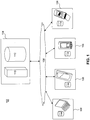
- FIG. 1 illustrates a block diagram of a mobile computing environment 102 that achieves background synchronization according to an embodiment of the invention. Included are a central system 104 and one or more remote systems 106, such as portable, hand-held mobile computing devices, e.g., laptop computing devices, personal digital assistants, cellular phones, and the like.
- the central system 104 and remote systems 106 communicate via any known means for a communication network 108, such as, but not limited to, the Internet.
- Central system 104 includes a synchronization system 110 and a consolidated database system 112.
- the consolidated database system 112 capably operates as a database manager and a database, where the database can further include index and table data, and the database manager can be any form of database management system (DBMS) and can include, but is not limited to, a device having a processor and memory for executing and storing instructions.
- DBMS database management system
- the consolidated database system 112 may include software, firmware, and hardware or some combination thereof and the database manager may be a DBMS such as SYBASE Adaptive Sever Enterprise®.
- the software may include one or more applications and an operating system.
- the hardware can include, but is not limited to, a processor, memory and user interface display.
- An optional input device such as a keyboard, mouse, stylus or any other pointing device, may be used.
- the database manager may store and manipulate data in database. Database manager may be used directly by system users, as a component of a software package or can be used to provide various services to an independent software package.
- Each remote system 106 preferably includes a remote database system 114.
- the remote database system 114 can further contain a subset of the data in the database of the consolidated database system 112, the subset of data including a database index and table data.
- the remote system 106 can include, but is not limited to, a device having a processor and memory for executing and storing instructions.
- the remote database system 114 may be provided as SYBASE SQL Anywhere UltraLite® and may include software, firmware, and hardware or some combination thereof.
- the software may include one or more applications and an operating system.
- the hardware can include, but is not limited to, a processor, memory and user interface display. An optional input device, such as a keypad, stylus or any other pointing device, may be used.
- the database of the consolidated database system 112 and the subset of that database in the remote database system 114 may be a collection of data which is managed and manipulated according to various logical data models, or views of stored data, as known to those skilled in the art. Examples of logical data models in the present database market include the relational model, using the industry-standard SQL query language. Database tables are known to those of skilled in the art and may further include several records, each record composed of several fields.
- manipulating data in a relational architecture system includes manipulation of tables, shared columns and indexes that may reside in the database.
- a row map store structure may maintain a mapping from a row identifier to a row state (row states are described further hereinbelow) and a row handle.
- the row identifier may be added to the end of the column list to act as part of a key for the index that provides an ordered list of columns and row identifiers.
- the row handle may contain the coordinates of the row data in the store structure.
- the row map is a linear array, indexed by the row identifier.
- the array is stored by allocating segments of the array on store pages, and linking them together in a tree with interior addressing nodes, with depth corresponding to a size of the row map.
- the leaves of the tree contain the actual array.
- the root and interior nodes serve to address the array with minimal input/output cost.
- Synchronization system 110 operates to ensure data integrity between the database of the consolidated database system 112 and the subset of that database in the remote database systems 114.
- the synchronization system 110 may be provided as SYBASE SQL Anywhere MobiLink® and may include software, firmware, and hardware or some combination thereof. Efficient data synchronization between the remote systems 106 and the central system 104 occurs by communicating changes to the data.
- a background synchronization process is achieved for the mobile computing environment 102 by creating a "snapshot" of the data on the remote database system 114 at a point in time to know what data changes should be uploaded to the central system 104 and what should be ignored.
- the snapshot employs metadata in the form of multiple types of bit values, including an upload value, as a row state for each row of data. This metadata must account for tracking of a row condition beyond merely a simple single bit to indicate an insert or delete of a row, since a row being synchronized in the background may also be being changed in the foreground.
- the metadata of the present invention tracks and identifies row(s) that are modified in the course of database operations that may be occurring even as one background synchronization is processed in order to ensure that any modification gets captured on a next background synchronization process.
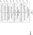
- FIG. 2 a block diagram for an overall flow of a synchronization process to ensure data integrity in a database environment in accordance with the present invention is presented.
- the synchronization there are few distinct exchanges of information, which limits the "chatting" of the protocol. This can be advantageous when communication may be slower and has higher latency, such as when using telephone lines or public wireless network connections, as is well appreciated by those skilled in the art.
- the initiation of a synchronization process occurs when there is an established connection between the remote system 106 and the central system 104 via communication network 108 upon a user selection to perform a data synchronization (block 200).
- the data to be synchronized is sent in an upload stream from the remote system 106 to the central system 104 (block 202).
- the building of the upload stream relies on the use of row state metadata to identify which rows to send to the central system 104 and the condition of those rows.
- row state metadata Through the use of the row state metadata, synchronization functionality occurs without using typical log transaction tracking and coalescing, as is well known in the art, and which is a much more complicated and time-consuming approach.
- the central system 104 Upon receipt of the upload stream, the central system 104 applies the upload stream to the consolidated database system 112 (block 204) and commits the changes from the upload stream on the consolidated database system 112 (block 206). With the data changes committed to complete the upload phase of the synchronization process, the central system 104 initiates a download phase by sending a response to the remote system 106 indicating that the commit of the upload stream is completed on the central system 104 (block 208). The central system 104 then builds and sends a download stream to the remote system 106 (block 210). The remote system 106 adjusts the states of the row metadata for the rows that were successfully uploaded (block 212) and applies the received download stream (block 214). Based on the data from the download stream, any necessary adjustments are made to the row state to commit the data from the download in the remote database system 114 (block 216) and complete the synchronization process.
- the process initiates when a user of remote system 106 performs a database operation (block 300), e.g., a delete, an update, or an add operation.
- a database operation e.g., a delete, an update, or an add operation.
- the metadata of the row state is used to reflect any change.
- the metadata includes four values that together provide the row state:
- the insert type value INSERT
- the delete type value NONE
- the commit state value INSERT NOT COMMITTED
- the upload state value NOT COMPUTED.
- a commit state value INSERT NOT COMMITTED
- an upload state value NOT COMPUTED.
- the POST-IMAGE value condition is used if the old version of the row has a delete type value that is not equal to REMOVE and the insert type value is POST-IMAGE or the delete type value is not equal to REMOVE and the commit state value equals MAYBE or INSERT COMMITTED.
- the delete type value DELETE.
- a stop synchronization setting may be used to allow certain data to not be subject to a synchronization process.
- the intent of the feature is to reduce the subset of rows that each remote system 106 holds from the consolidated database 114. That is, the deletes are not really deletes from the point of view of the consolidated database 114, and so they should not be uploaded.
- the REMOVE value for the delete type is used to reflect this.
- the process continues by committing the database operation (block 302).
- the commitment of the database operation depends on whether there has been a prior synchronization of the affected row(s). For a delete, if the row has never been synchronized, then it is removed. If the row has been synchronized, then it is not removed, because the delete operation needs to be synchronized to the consolidated database first.
- a transaction to update a row is committed, the states of all rows affected by the transaction are modified to reflect the commit.
- an update is synchronized, both the old and new versions of the row are needed to allow conflict detection and resolution. The old row is then deleted from the database and the new row simply becomes a normal row. The addition of a row results in the row being marked as committed.
- the upload state value conditions include NOT COMPUTED, INCLUDED, and EXCLUDED, where the NOT COMPUTED value is used to indicate that no commits have taken place on the row since the upload of the synchronization began, the INCLUDED value is used to indicate that a row should be part of the synchronization, and the EXCLUDED value is used to indicate that a row is not part of the synchronization.
- These upload state values of the row state metadata enable the synchronization operation to work with a snapshot of the committed state of the database at the moment the upload begins. With this snapshot, there can be changes to the database which won't affect what gets uploaded, and the integrity of the uploaded data is ensured as the remote system 106 continues to process database transactions.
- a process for determining the upload state value portion of the row state metadata is presented with reference to the block flow diagram of FIG. 4 .
- An initial check of the upload state value occurs to identify whether it actually needs to be set (block 400).
- the upload state values of the row state are set to either INCLUDED or EXCLUDED when a commit of a row occurs during a synchronization and are cleared back to NOT COMPUTED upon completion of the synchronization.
- the upload state value is already set to INCLUDED or EXCLUDED, then no change to the upload state value is needed, since a set upload state value indicates that this is not the first commit on this row since the upload began. Further, if the commit state value condition of the row state is MAYBE, then the row has already been uploaded but has yet to be confirmed as successfully completed, and no change should occur for the upload state value portion of that row. In these situations, the upload state value is maintained (block 402) and the process is complete.
- the upload state value does need to be set (block 400 is affirmative), i.e., the commit state value condition is not equal to MAYBE and the upload state value condition is equal to NOT COMPUTED, a determination is made to identify how the row would be handled for the synchronization if the row were in its uncommitted state (block 404). If it is identified that the system would upload the row (block 404 is affirmative), then the upload value is set to INCLUDED (block 406). Otherwise, the upload value is set to EXCLUDED (block 408).
- a row needs to be uploaded and the upload state value condition is set to INCLUDED if the delete type value condition is equal to DELETE and the insert type value condition is equal to NORMAL, or if the delete type value condition is equal to REMOVE and the insert type value condition is not equal to NORMAL.
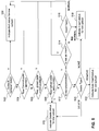
- a process for interpretation of the upload state value condition to affect the synchronization process is presented with reference to the block flow diagram of FIG. 5 .
- the process is utilized during an upload to determine how each row should be uploaded by identifying one of four status indicators, either a Null status which indicates that the row does not get uploaded, an Insert status which indicates that the row is to be uploaded as an insert, a Delete status which indicates that the row is to be uploaded as a delete, or a Lost Insert status which indicates that the row is to be uploaded as a lost insert.
- the Lost Insert is very similar to an Insert but helps account for a row with a REMOVE setting as the delete type as a result of the stop synchronization setting.
- the synchronization system 110 would not download a row that was just uploaded. That is, if the consolidated database system 112 determines that a Lost Insert row should be downloaded to the remote system 106, normally the synchronization system 110 will optimize the download to omit downloading that row, since the synchronization system 110 knows that the remote database system 106 already contains that row. However, through the use of the Lost Insert status, the row is identified to the synchronization system 110 as being removed from the remote database. This disables the normal optimization and allows the row to be downloaded to the remote system 106.
- the process continues by determining if the row is an uncommitted (block 512) and an insert (block 514). If so, then the row is skipped since uncommitted inserts are not uploaded, and the Null status is indicated (block 502). If not, the row is an uncommitted delete, and the insert type is checked (block 516). If the insert type is NORMAL, the row does not need to be included in the synchronization and the Null status is indicated (block 502). For an insert types other than NORMAL, an Insert status is indicated (block 518).
- the synchronization process occurs with the assurance that the metadata for each row properly reflects an accurate row state.
- the inclusion of the upload value condition allows concurrent access to the remote database while a synchronization is taking place, and there is no need to restrict access to a read-only mode or raise an error on attempts to modify the remote database. Accordingly, an efficient and seamless utilization of the remote database occurs, which is especially beneficial in mobile database environments.
- system and components of embodiments described herein are implemented using well known computers, such as example computer 602 shown in FIG. 6 .
- central system 104 or remote systems 106 can be implemented using computer(s) 602.
- the computer 602 can be any commercially available and well known computer capable of performing the functions described herein, such as computers available from International Business Machines, Apple, Sun, HP, Dell, Compaq, Digital, Cray, etc.
- the computer 602 includes one or more processors (also called central processing units, or CPUs), such as a processor 606.
- processors also called central processing units, or CPUs
- the processor 606 is connected to a communication bus 604.
- the computer 602 also includes a main or primary memory 608, such as random access memory (RAM).
- the primary memory 508 has stored therein control logic 625A (computer software), and data.
- the computer 602 also includes one or more secondary storage devices 610.
- the secondary storage devices 610 include, for example, a hard disk drive 612 and/or a removable storage device or drive 614, as well as other types of storage devices, such as memory cards and memory sticks.
- the removable storage drive 614 represents a floppy disk drive, a magnetic tape drive, a compact disk drive, an optical storage device, tape backup, etc.
- the removable storage drive 614 interacts with a removable storage unit 616.
- the removable storage unit 616 includes a computer useable or readable storage medium 624 having stored therein computer software 628B (control logic) and/or data.
- Removable storage unit 616 represents a floppy disk, magnetic tape, compact disk, DVD, optical storage disk, or any other computer data storage device.
- the removable storage drive 614 reads from and/or writes to the removable storage unit 616 in a well known manner.
- the computer 602 also includes input/output/display devices 622, such as monitors, keyboards, pointing devices, etc.
- the computer 602 further includes a communication or network interface 618.
- the network interface 618 enables the computer 602 to communicate with remote devices.
- the network interface 618 allows the computer 602 to communicate over communication networks or mediums 624B (representing a form of a computer useable or readable medium), such as LANs, WANs, the Internet, etc.
- the network interface 618 may interface with remote sites or networks via wired or wireless connections.
- Control logic 628C may be transmitted to and from the computer 602 via the communication medium 624B. More particularly, the computer 602 may receive and transmit carrier waves (electromagnetic signals) modulated with control logic 630 via the communication medium 624B.
- carrier waves electromagnetic signals
- Any apparatus or manufacture comprising a computer useable or readable medium having control logic (software) stored therein is referred to herein as a computer program product or program storage device.
- the invention can work with software, hardware, and/or operating system implementations other than those described herein. Any software, hardware, and operating system implementations suitable for performing the functions described herein can be used.
Landscapes
- Engineering & Computer Science (AREA)
- Databases & Information Systems (AREA)
- Theoretical Computer Science (AREA)
- Computing Systems (AREA)
- Data Mining & Analysis (AREA)
- Physics & Mathematics (AREA)
- General Engineering & Computer Science (AREA)
- General Physics & Mathematics (AREA)
- Information Retrieval, Db Structures And Fs Structures Therefor (AREA)
Description
- The present invention is generally directed to maintaining data integrity in a database environment, and more particularly, to maintaining data integrity through background synchronization in the database environment.
- In today's expanding computing environments, the workforce for many businesses performs its job using portable, mobile computing devices, such as personal computing laptops, tablets, personal digital assistants, smart phones, and the like. These remote systems typically run mobile business applications that adopt an "always-available"/"occasionally-connected" architecture. In this manner, the remote systems store data locally, so that their use of data applications can continue whether or not a network is available. Despite this local data store, the ultimate home of the data for business applications is not the remote system but a consolidated database on a company server. Periodically, the data being utilized and updated among the mobile workforce needs to be synchronized with this central data store of the consolidated database over a wired or wireless network connection to ensure data integrity.
- While data synchronization clearly is necessary to maintain data consistency for mobile computing environments, synchronization operations that move data from the mobile device to the consolidated server and from the consolidated server to the mobile device, can demand substantial computer and network resources, and often require a non-trivial amount of time to complete. These operations include tracking data changes on the mobile device and at the server, sending the right changes, making sure that unique key values for the data are preserved, and identifying and resolving conflicts when they occur. Normally, the control necessary for the data synchronization process requires that data access in the remote systems be restricted while the synchronization process occurs, allowing, at most, read-only access to the data. However, the lack of support for concurrent transactional access to the remote database while a synchronization operation is taking place diminishes performance and efficiency.
- Accordingly, a need exists for an approach to ensuring data integrity in a database through synchronization that operates in the background of data modification operations in remote database environments. The present invention addresses such a need.
-
US 5924096 discloses methods for synchronizing local copies of a distributed database. Each data item in the database has an associated timestamp or other tag. An index into the tags in maintained and used to create an event list for use in synchronizing the local copies. - Aspects of the invention are set out in the independent claims. Certain preferred features are set out in the dependent claims.
- The present invention is directed to systems, methods and computer program products for maintaining data integrity in a database environment.
- In an embodiment, the invention operates by initiating a process in a remote database system for synchronization of remote data from the remote database system with consolidated data of a consolidated database, and utilizing metadata for each row of the remote data to allow transactional access to the remote data while the synchronization process occurs.
- Further features and advantages of the present invention, as well as the structure and operation of various embodiments thereof, are described in detail below with reference to the accompanying drawings. It is noted that the invention is not limited to the specific embodiments described herein. Such embodiments are presented herein for illustrative purposes only. Additional embodiments will be apparent to persons skilled in the relevant art(s) based on the teachings contained herein.
- The accompanying drawings, which are incorporated herein and form part of the specification, illustrate the present invention and, together with the description, further serve to explain the principles of the invention and to enable a person skilled in the relevant art(s) to make and use the invention.
-
FIG. 1 illustrates a block diagram of an example computing environment that achieves background synchronization according to an embodiment of the invention. -
FIG. 2 illustrates a block diagram for an overall flow of a synchronization process to ensure data integrity in a database environment according to an embodiment of the invention. -
FIG. 3 illustrates a block diagram of an overall flow for maintaining metadata for a synchronization process according to an embodiment of the invention. -
FIG. 4 illustrates a block diagram of an overall flow for determining an upload state value portion of the metadata according to an embodiment of the invention. -
FIG. 5 illustrates a block diagram of an overall flow for interpretation of the upload state value to affect the synchronization process according to an embodiment of the present invention. -
FIG. 6 illustrates an example computer useful for implementing components of the invention. - The features and advantages of the present invention will become more apparent from the detailed description set forth below when taken in conjunction with the drawings. In the drawings, like reference numbers generally indicate identical, functionally similar, and/or structurally similar elements. Generally, the drawing in which an element first appears is indicated by the leftmost digit(s) in the corresponding reference number.
- In the environment of mobile, and often hand-held, computing systems, utilization of local database applications have to support the needs of data synchronization of the local database with a consolidated database on a network server. An example of a known database application that is more portable across multiple devices, including ones having limited computational power, is described in
US Patent 6341288 , entitled Database System with Methodology for Accessing a Database from Portable Devices, which is assigned to the assignee of the present invention. As computing capabilities, memory devices, and other system components of mobile systems have improved in recent years to support multi-threaded processing, correspondingly, a need has increased for a synchronization process that not only maintains data integrity, but also capably operates as a background process to allow substantially continual transactional access and improve efficiency and performance in today's fast-paced, mobile working environment. -
FIG. 1 illustrates a block diagram of amobile computing environment 102 that achieves background synchronization according to an embodiment of the invention. Included are acentral system 104 and one or moreremote systems 106, such as portable, hand-held mobile computing devices, e.g., laptop computing devices, personal digital assistants, cellular phones, and the like. Thecentral system 104 andremote systems 106 communicate via any known means for acommunication network 108, such as, but not limited to, the Internet. -
Central system 104 includes asynchronization system 110 and a consolidateddatabase system 112. The consolidateddatabase system 112 capably operates as a database manager and a database, where the database can further include index and table data, and the database manager can be any form of database management system (DBMS) and can include, but is not limited to, a device having a processor and memory for executing and storing instructions. In an example, not intended to limit the invention, the consolidateddatabase system 112 may include software, firmware, and hardware or some combination thereof and the database manager may be a DBMS such as SYBASE Adaptive Sever Enterprise®. The software may include one or more applications and an operating system. The hardware can include, but is not limited to, a processor, memory and user interface display. An optional input device, such as a keyboard, mouse, stylus or any other pointing device, may be used. The database manager may store and manipulate data in database. Database manager may be used directly by system users, as a component of a software package or can be used to provide various services to an independent software package. - Each
remote system 106 preferably includes aremote database system 114. Theremote database system 114 can further contain a subset of the data in the database of the consolidateddatabase system 112, the subset of data including a database index and table data. Theremote system 106 can include, but is not limited to, a device having a processor and memory for executing and storing instructions. In an example, not intended to limit the invention, theremote database system 114 may be provided as SYBASE SQL Anywhere UltraLite® and may include software, firmware, and hardware or some combination thereof. The software may include one or more applications and an operating system. The hardware can include, but is not limited to, a processor, memory and user interface display. An optional input device, such as a keypad, stylus or any other pointing device, may be used. - The database of the consolidated
database system 112 and the subset of that database in theremote database system 114 may be a collection of data which is managed and manipulated according to various logical data models, or views of stored data, as known to those skilled in the art. Examples of logical data models in the present database market include the relational model, using the industry-standard SQL query language. Database tables are known to those of skilled in the art and may further include several records, each record composed of several fields. - As an example, manipulating data in a relational architecture system includes manipulation of tables, shared columns and indexes that may reside in the database. For example, in the
remote database systems 114, a row map store structure may maintain a mapping from a row identifier to a row state (row states are described further hereinbelow) and a row handle. The row identifier may be added to the end of the column list to act as part of a key for the index that provides an ordered list of columns and row identifiers. The row handle may contain the coordinates of the row data in the store structure. Conceptually, the row map is a linear array, indexed by the row identifier. The array is stored by allocating segments of the array on store pages, and linking them together in a tree with interior addressing nodes, with depth corresponding to a size of the row map. With similarities to known B-tree structures, the leaves of the tree contain the actual array. The root and interior nodes serve to address the array with minimal input/output cost. -
Synchronization system 110 operates to ensure data integrity between the database of theconsolidated database system 112 and the subset of that database in theremote database systems 114. In an example, not intended to limit the invention, thesynchronization system 110 may be provided as SYBASE SQL Anywhere MobiLink® and may include software, firmware, and hardware or some combination thereof. Efficient data synchronization between theremote systems 106 and thecentral system 104 occurs by communicating changes to the data. - In a preferred embodiment, a background synchronization process is achieved for the
mobile computing environment 102 by creating a "snapshot" of the data on theremote database system 114 at a point in time to know what data changes should be uploaded to thecentral system 104 and what should be ignored. The snapshot employs metadata in the form of multiple types of bit values, including an upload value, as a row state for each row of data. This metadata must account for tracking of a row condition beyond merely a simple single bit to indicate an insert or delete of a row, since a row being synchronized in the background may also be being changed in the foreground. Thus, the metadata of the present invention tracks and identifies row(s) that are modified in the course of database operations that may be occurring even as one background synchronization is processed in order to ensure that any modification gets captured on a next background synchronization process. - Referring now to the
FIG. 2 , a block diagram for an overall flow of a synchronization process to ensure data integrity in a database environment in accordance with the present invention is presented. As will be described, during the synchronization, there are few distinct exchanges of information, which limits the "chatting" of the protocol. This can be advantageous when communication may be slower and has higher latency, such as when using telephone lines or public wireless network connections, as is well appreciated by those skilled in the art. - Typically, the initiation of a synchronization process occurs when there is an established connection between the
remote system 106 and thecentral system 104 viacommunication network 108 upon a user selection to perform a data synchronization (block 200). The data to be synchronized is sent in an upload stream from theremote system 106 to the central system 104 (block 202). In a preferred embodiment, the building of the upload stream relies on the use of row state metadata to identify which rows to send to thecentral system 104 and the condition of those rows. Through the use of the row state metadata, synchronization functionality occurs without using typical log transaction tracking and coalescing, as is well known in the art, and which is a much more complicated and time-consuming approach. - Upon receipt of the upload stream, the
central system 104 applies the upload stream to the consolidated database system 112 (block 204) and commits the changes from the upload stream on the consolidated database system 112 (block 206). With the data changes committed to complete the upload phase of the synchronization process, thecentral system 104 initiates a download phase by sending a response to theremote system 106 indicating that the commit of the upload stream is completed on the central system 104 (block 208). Thecentral system 104 then builds and sends a download stream to the remote system 106 (block 210). Theremote system 106 adjusts the states of the row metadata for the rows that were successfully uploaded (block 212) and applies the received download stream (block 214). Based on the data from the download stream, any necessary adjustments are made to the row state to commit the data from the download in the remote database system 114 (block 216) and complete the synchronization process. - Referring now to
FIG. 3 , an overall process is presented for maintaining the metadata to achieve the synchronization process ofFIG. 2 in accordance with the present invention. The process initiates when a user ofremote system 106 performs a database operation (block 300), e.g., a delete, an update, or an add operation. Depending upon which operation occurs, the metadata of the row state is used to reflect any change. As represented in the following list, in a preferred embodiment, the metadata includes four values that together provide the row state: - insert type (NORMAL, INSERT, POST-IMAGE);
- delete type (NONE, DELETE, REMOVE);
- commit state (INSERT COMMITTED, INSERT NOT COMMITTED, MAYBE);
and - upload state (NOT COMPUTED, INCLUDED, EXCLUDED).
- By way of example, on an initial insert of a row as the database operation, the insert type value = INSERT, the delete type value = NONE, the commit state value = INSERT NOT COMMITTED, and the upload state value = NOT COMPUTED. On an update of a row, the new version of the row is marked with delete type value = NONE, a commit state value = INSERT NOT COMMITTED, and an upload state value = NOT COMPUTED. For the insert type value on the row update, the POST-IMAGE value condition is used if the old version of the row has a delete type value that is not equal to REMOVE and the insert type value is POST-IMAGE or the delete type value is not equal to REMOVE and the commit state value equals MAYBE or INSERT COMMITTED. The word "maybe" is used in those cases where changes to a row "may" have been uploaded, but there is uncertainty because an acknowledgement has not been received yet. Otherwise, the insert type value = INSERT. With either POST-IMAGE or INSERT for the insert type value of the new row, the old version of the updated row is changed to have a delete type value = DELETE.
- On a row delete, usually the delete type value = DELETE. However, in an embodiment, a stop synchronization setting may be used to allow certain data to not be subject to a synchronization process. The intent of the feature is to reduce the subset of rows that each
remote system 106 holds from theconsolidated database 114. That is, the deletes are not really deletes from the point of view of theconsolidated database 114, and so they should not be uploaded. The REMOVE value for the delete type is used to reflect this. - After the performance of a database operation, the process continues by committing the database operation (block 302). The commitment of the database operation depends on whether there has been a prior synchronization of the affected row(s). For a delete, if the row has never been synchronized, then it is removed. If the row has been synchronized, then it is not removed, because the delete operation needs to be synchronized to the consolidated database first. When a transaction to update a row is committed, the states of all rows affected by the transaction are modified to reflect the commit. When an update is synchronized, both the old and new versions of the row are needed to allow conflict detection and resolution. The old row is then deleted from the database and the new row simply becomes a normal row. The addition of a row results in the row being marked as committed.
- For each database operation (insert, update and delete), additional flagging occurs via an update to the upload state value condition of the row state metadata when a check for a synchronization process is affirmative (block 304) to condition the row processing during the synchronization (block 306). If no synchronization process is occurring (block 304 is negative), the remote database system ignores the upload state value portion of the row state and continues with standard processing of the database transaction (block 300).
- As indicated in the list above, in a preferred embodiment, the upload state value conditions include NOT COMPUTED, INCLUDED, and EXCLUDED, where the NOT COMPUTED value is used to indicate that no commits have taken place on the row since the upload of the synchronization began, the INCLUDED value is used to indicate that a row should be part of the synchronization, and the EXCLUDED value is used to indicate that a row is not part of the synchronization. These upload state values of the row state metadata enable the synchronization operation to work with a snapshot of the committed state of the database at the moment the upload begins. With this snapshot, there can be changes to the database which won't affect what gets uploaded, and the integrity of the uploaded data is ensured as the
remote system 106 continues to process database transactions. - A process for determining the upload state value portion of the row state metadata is presented with reference to the block flow diagram of
FIG. 4 . An initial check of the upload state value occurs to identify whether it actually needs to be set (block 400). In general, the upload state values of the row state are set to either INCLUDED or EXCLUDED when a commit of a row occurs during a synchronization and are cleared back to NOT COMPUTED upon completion of the synchronization. - Thus, if the upload state value is already set to INCLUDED or EXCLUDED, then no change to the upload state value is needed, since a set upload state value indicates that this is not the first commit on this row since the upload began. Further, if the commit state value condition of the row state is MAYBE, then the row has already been uploaded but has yet to be confirmed as successfully completed, and no change should occur for the upload state value portion of that row. In these situations, the upload state value is maintained (block 402) and the process is complete.
- If the upload state value does need to be set (block 400 is affirmative), i.e., the commit state value condition is not equal to MAYBE and the upload state value condition is equal to NOT COMPUTED, a determination is made to identify how the row would be handled for the synchronization if the row were in its uncommitted state (block 404). If it is identified that the system would upload the row (block 404 is affirmative), then the upload value is set to INCLUDED (block 406). Otherwise, the upload value is set to EXCLUDED (block 408).
- In a preferred embodiment, a row does not need to be uploaded and the upload state value condition is set to EXCLUDED for rows that are found to have a row state represented with an insert type = NORMAL, commit state = INSERT COMMITTED, and delete type = NONE or REMOVE. A row needs to be uploaded and the upload state value condition is set to INCLUDED if the delete type value condition is equal to DELETE and the insert type value condition is equal to NORMAL, or if the delete type value condition is equal to REMOVE and the insert type value condition is not equal to NORMAL.
- A process for interpretation of the upload state value condition to affect the synchronization process is presented with reference to the block flow diagram of
FIG. 5 . In accordance with an embodiment of the present invention, the process is utilized during an upload to determine how each row should be uploaded by identifying one of four status indicators, either a Null status which indicates that the row does not get uploaded, an Insert status which indicates that the row is to be uploaded as an insert, a Delete status which indicates that the row is to be uploaded as a delete, or a Lost Insert status which indicates that the row is to be uploaded as a lost insert. The Lost Insert is very similar to an Insert but helps account for a row with a REMOVE setting as the delete type as a result of the stop synchronization setting. In general, thesynchronization system 110 would not download a row that was just uploaded. That is, if theconsolidated database system 112 determines that a Lost Insert row should be downloaded to theremote system 106, normally thesynchronization system 110 will optimize the download to omit downloading that row, since thesynchronization system 110 knows that theremote database system 106 already contains that row. However, through the use of the Lost Insert status, the row is identified to thesynchronization system 110 as being removed from the remote database. This disables the normal optimization and allows the row to be downloaded to theremote system 106. - The process initiates under an assumption that a row being considered is not in a 'normal' state, since in a preferred embodiment, the map iteration over the rows is conditioned to skip 'normal' rows, i.e., those rows having an insert type = NORMAL, a delete type = NONE, a commit state value = INSERT COMMITTED, and an upload state value = NOT COMPUTED. Given a row that is not in the 'normal' state, the process determines if the row state is equivalent to a 'remove' state (block 500). A 'remove' state preferably refers to an insert type = NORMAL, a delete type = REMOVE, a commit state value = INSERT COMMITTED, and an upload state value = NOT COMPUTED. When the row is in a 'remove' state, it does not need to be considered for upload (block 502) and a Null status is indicated.
- If the row is not in a 'normal' state or in a 'remove' state, the process continues by determining if the row commit state value = MAYBE (block 504). If so, the row was already uploaded in the synchronization process that is in progress and does not need to be considered for upload again. Accordingly, a Null status is indicated (block 502). This check ensures that an upload that occurs as a two pass process is accounted for, where, for example, a first pass uploads inserts and updates, and a second pass uploads deletes, with each pass being implemented using a map iterate.
- When the row commit state value is not MAYBE, the process continues by checking the upload state value of the row. If the upload state value = EXCLUDED (block 506), then the row does not need to be considered for upload and the Null status is indicated (block 502). If the upload state value = INCLUDED (block 508), then a status of Delete is indicated (block 510), since an insert committed after the upload began does not upload and thus would not have an upload state value of INCLUDED.
- To account for a row that has been modified but not committed (i.e., has an upload state value = NOT COMPUTED), the process continues by determining if the row is an uncommitted (block 512) and an insert (block 514). If so, then the row is skipped since uncommitted inserts are not uploaded, and the Null status is indicated (block 502). If not, the row is an uncommitted delete, and the insert type is checked (block 516). If the insert type is NORMAL, the row does not need to be included in the synchronization and the Null status is indicated (block 502). For an insert types other than NORMAL, an Insert status is indicated (block 518).
- If none of these conditions are found, then the row is a committed row that was committed before the upload began. The delete type value condition is used to determine the status indicator (block 520). For a delete type = NONE, the process returns an Insert indicator (block 518). For a delete type = REMOVE, the process returns a Lost Insert indicator (block 522). And, for a delete type = DELETE, the process returns a Delete indicator (block 510).
- In this manner, the synchronization process occurs with the assurance that the metadata for each row properly reflects an accurate row state. As described, the inclusion of the upload value condition allows concurrent access to the remote database while a synchronization is taking place, and there is no need to restrict access to a read-only mode or raise an error on attempts to modify the remote database. Accordingly, an efficient and seamless utilization of the remote database occurs, which is especially beneficial in mobile database environments.
- In an embodiment of the present invention, the system and components of embodiments described herein are implemented using well known computers, such as example computer 602 shown in
FIG. 6 . For example,central system 104 orremote systems 106 can be implemented using computer(s) 602. - The computer 602 can be any commercially available and well known computer capable of performing the functions described herein, such as computers available from International Business Machines, Apple, Sun, HP, Dell, Compaq, Digital, Cray, etc.
- The computer 602 includes one or more processors (also called central processing units, or CPUs), such as a
processor 606. Theprocessor 606 is connected to acommunication bus 604. - The computer 602 also includes a main or
primary memory 608, such as random access memory (RAM). Theprimary memory 508 has stored therein control logic 625A (computer software), and data. - The computer 602 also includes one or more
secondary storage devices 610. Thesecondary storage devices 610 include, for example, ahard disk drive 612 and/or a removable storage device or drive 614, as well as other types of storage devices, such as memory cards and memory sticks. Theremovable storage drive 614 represents a floppy disk drive, a magnetic tape drive, a compact disk drive, an optical storage device, tape backup, etc. - The
removable storage drive 614 interacts with aremovable storage unit 616. Theremovable storage unit 616 includes a computer useable or readable storage medium 624 having stored thereincomputer software 628B (control logic) and/or data.Removable storage unit 616 represents a floppy disk, magnetic tape, compact disk, DVD, optical storage disk, or any other computer data storage device. Theremovable storage drive 614 reads from and/or writes to theremovable storage unit 616 in a well known manner. - The computer 602 also includes input/output/
display devices 622, such as monitors, keyboards, pointing devices, etc. - The computer 602 further includes a communication or
network interface 618. Thenetwork interface 618 enables the computer 602 to communicate with remote devices. For example, thenetwork interface 618 allows the computer 602 to communicate over communication networks ormediums 624B (representing a form of a computer useable or readable medium), such as LANs, WANs, the Internet, etc. Thenetwork interface 618 may interface with remote sites or networks via wired or wireless connections. -
Control logic 628C may be transmitted to and from the computer 602 via thecommunication medium 624B. More particularly, the computer 602 may receive and transmit carrier waves (electromagnetic signals) modulated withcontrol logic 630 via thecommunication medium 624B. - Any apparatus or manufacture comprising a computer useable or readable medium having control logic (software) stored therein is referred to herein as a computer program product or program storage device. This includes, but is not limited to, the computer 602, the
main memory 608,secondary storage devices 610, theremovable storage unit 616 and the carrier waves modulated withcontrol logic 630. Such computer program products, having control logic stored therein that, when executed by one or more data processing devices, cause such data processing devices to operate as described herein, represent embodiments of the invention. - The invention can work with software, hardware, and/or operating system implementations other than those described herein. Any software, hardware, and operating system implementations suitable for performing the functions described herein can be used.
- While the present invention has been described with reference to a mobile computing environment, this is meant as illustrative and not restrictive of the environments where the background synchronization of the present invention may find application or that would benefit from the functions as described herein.
Claims (8)
- A method for synchronizing data between a first database system (112) and a second, remote database system (114) in a background process whilst allowing concurrent access to the remote database system, the method comprising:initiating a background process in the remote database system for synchronization of remote data from the remote database system with data of the first database system; andutilizing metadata for each row of the remote data to allow modification of the remote data while the background synchronization process occurs, wherein the metadata includes at least an upload condition attribute to control row processing during the synchronization, the upload condition attribute arranged to have one of a set of predetermined values each denoting a respective upload condition, comprising:a first value indicating that the row is to be included in the synchronization process,a second value indicating that the row is to be excluded from the synchronization process; anda third value indicating that no changes have been committed to the row after initiation of the synchronization process;wherein utilizing the metadata comprises, in response to an insert, update or delete database operation being committed to a row of the remote data:determining whether the synchronization process is occurring;in response to determining that the synchronization process is occurring such that the commit of the row has occurred during the synchronization process, setting the upload condition attribute for the row to the first value to indicate that the row is to be included in the synchronization process or to the second value to indicate that the row is to be excluded from the synchronization process;including or excluding the row in the synchronization process in accordance with the upload condition attribute; andsetting the upload condition attribute to the third value upon completion of the synchronization process.
- The method of claim 1, further comprising storing the metadata for each row of the remote data in the remote database system.
- A method according to claim 1 or 2, wherein the first value of the upload condition attribute is set for a delete operation and indicates that the row is to be uploaded as a delete.
- A method according to any of the preceding claims, wherein the second value of the upload condition is set for an insert operation committed after start of the synchronization process.
- A system for synchronization of data between databases, the system comprising:a communication network (108);a first system (104) coupled to the communication network and including a first database (112); andat least one second system (106) coupled to the communication network and including a second, remote database (114), the at least one second system initiating a background process for synchronization of remote data from the remote database with data of the first database whilst allowing concurrent access to the remote database system and utilizing metadata for each row of the remote data to allow modification of the remote data in the at least one second system while the synchronization process occurs, wherein the metadata includes at least an upload condition attribute to control row processing during the synchronization, the upload condition attribute arranged to have one of a set of predetermined values each denoting a respective upload condition, comprising:a first value indicating that the row is to be included in the synchronization process,a second value indicating that the row is to be excluded from the synchronization process; anda third value indicating that no changes have been committed to the row after initiation of the synchronization process;wherein the second system is configured, in response to an insert, update or delete database operation being committed to a row of the remote data, to:determine whether the synchronization process is occurring;in response to determining that the synchronization process is occurring such that the commit of the row has occurred during the synchronization process, set the upload condition attribute for the row to the first value to indicate that the row is to be included in the synchronization process or to the second value to indicate that the row is to be excluded from the synchronization process;include or exclude the row during the synchronization process in accordance with the upload condition attribute; andset the upload condition attribute to the third value upon completion of the synchronization process.
- The system of claim 5 wherein the first system further includes a synchronization system (110) coupled to the first database.
- The system of claim 5 or 6 wherein the at least one second system comprises a mobile computing device.
- A computer program product comprising a computer useable medium having computer program logic recorded thereon for enabling a processor to perform data synchronization between databases, the computer program logic comprising means for performing the method of any one of claims 1 to 4.
Applications Claiming Priority (2)
| Application Number | Priority Date | Filing Date | Title |
|---|---|---|---|
| US12/336,693 US8380663B2 (en) | 2008-12-17 | 2008-12-17 | Data integrity in a database environment through background synchronization |
| PCT/US2009/066538 WO2010077549A2 (en) | 2008-12-17 | 2009-12-03 | Data integrity in a database environment through background synchronization |
Publications (3)
| Publication Number | Publication Date |
|---|---|
| EP2380090A2 EP2380090A2 (en) | 2011-10-26 |
| EP2380090A4 EP2380090A4 (en) | 2014-01-15 |
| EP2380090B1 true EP2380090B1 (en) | 2019-04-10 |
Family
ID=42241743
Family Applications (1)
| Application Number | Title | Priority Date | Filing Date |
|---|---|---|---|
| EP09836655.2A Active EP2380090B1 (en) | 2008-12-17 | 2009-12-03 | Data integrity in a database environment through background synchronization |
Country Status (4)
| Country | Link |
|---|---|
| US (1) | US8380663B2 (en) |
| EP (1) | EP2380090B1 (en) |
| CN (1) | CN102272751B (en) |
| WO (1) | WO2010077549A2 (en) |
Families Citing this family (12)
| Publication number | Priority date | Publication date | Assignee | Title |
|---|---|---|---|---|
| KR101622604B1 (en) * | 2009-05-19 | 2016-05-31 | 엘지전자 주식회사 | Mobile terminal and method for processing process thereof |
| US11308490B2 (en) * | 2010-07-28 | 2022-04-19 | Cox Communications, Inc. | Security system and method that allows users to securely setup and maintain system security for all business systems |
| CN102629365B (en) * | 2012-03-09 | 2015-11-25 | 北京思特奇信息技术股份有限公司 | The data base processing method of inter-library business and system in a kind of mobile NGCRM system |
| US10795910B2 (en) | 2013-12-31 | 2020-10-06 | Sybase, Inc. | Robust communication system for guaranteed message sequencing with the detection of duplicate senders |
| US9405788B2 (en) | 2014-01-24 | 2016-08-02 | International Business Machines Corporation | Mass delete restriction in a database |
| US10397319B2 (en) | 2015-11-24 | 2019-08-27 | Dropbox, Inc. | Server-side selective synchronization |
| US20170177656A1 (en) * | 2015-12-18 | 2017-06-22 | Wal-Mart Stores, Inc. | Systems and methods for resolving data discrepancy |
| CN118312566A (en) * | 2019-04-12 | 2024-07-09 | 创新先进技术有限公司 | Data synchronization method and device |
| US11829334B2 (en) | 2020-06-12 | 2023-11-28 | International Business Machines Corporation | Per row database resynchronization |
| CN112800136A (en) * | 2021-01-30 | 2021-05-14 | 上海宝旗信息科技有限公司 | Data selective cascade synchronization tool and synchronization method thereof |
| CN114048266A (en) * | 2021-11-15 | 2022-02-15 | 中国联合网络通信集团有限公司 | Database data synchronization method, device and computer readable storage medium |
| US12470812B2 (en) * | 2023-10-18 | 2025-11-11 | Getac Technology Corporation | Photographic system and control method for heterogeneous video architecture |
Citations (1)
| Publication number | Priority date | Publication date | Assignee | Title |
|---|---|---|---|---|
| US7113963B1 (en) * | 2000-11-10 | 2006-09-26 | Palmsource, Inc. | Optimized database technique to enable faster data synchronization |
Family Cites Families (22)
| Publication number | Priority date | Publication date | Assignee | Title |
|---|---|---|---|---|
| US5924096A (en) * | 1997-10-15 | 1999-07-13 | Novell, Inc. | Distributed database using indexed into tags to tracks events according to type, update cache, create virtual update log on demand |
| US6341288B1 (en) * | 1998-07-29 | 2002-01-22 | Sybase, Inc. | Database system with methodology for accessing a database from portable devices |
| US6499039B1 (en) * | 1999-09-23 | 2002-12-24 | Emc Corporation | Reorganization of striped data during file system expansion in a data storage system |
| US6748447B1 (en) * | 2000-04-07 | 2004-06-08 | Network Appliance, Inc. | Method and apparatus for scalable distribution of information in a distributed network |
| US6631386B1 (en) * | 2000-04-22 | 2003-10-07 | Oracle Corp. | Database version control subsystem and method for use with database management system |
| US20030023759A1 (en) * | 2000-11-30 | 2003-01-30 | Jack Littleton | System and method for provisioning telephony services via a personal digital assistant |
| US6704745B2 (en) * | 2000-12-11 | 2004-03-09 | Microsoft Corporation | Transforming data between first organization in a data store and hierarchical organization in a dataset |
| CN1591403A (en) * | 2001-11-09 | 2005-03-09 | 无锡永中科技有限公司 | Edition compatible data processing system |
| US7769722B1 (en) * | 2006-12-08 | 2010-08-03 | Emc Corporation | Replication and restoration of multiple data storage object types in a data network |
| US7890091B2 (en) * | 2003-05-08 | 2011-02-15 | Good Technology, Inc. | Collaborative data and intelligent synchronization for mobile devices |
| US7398285B2 (en) * | 2003-07-30 | 2008-07-08 | International Business Machines Corporation | Apparatus and system for asynchronous replication of a hierarchically-indexed data store |
| US7146386B2 (en) * | 2004-03-29 | 2006-12-05 | Microsoft Corporation | System and method for a snapshot query during database recovery |
| US7555531B2 (en) | 2004-04-15 | 2009-06-30 | Microsoft Corporation | Efficient algorithm and protocol for remote differential compression |
| US7774319B2 (en) * | 2004-08-11 | 2010-08-10 | Sap Ag | System and method for an optimistic database access |
| CA2484694A1 (en) * | 2004-10-14 | 2006-04-14 | Alcatel | Database ram cache |
| US7415487B2 (en) * | 2004-12-17 | 2008-08-19 | Amazon Technologies, Inc. | Apparatus and method for data warehousing |
| US20070190978A1 (en) * | 2005-01-13 | 2007-08-16 | Ianywhere Solutions, Inc. | System and Methodology for Extending Enterprise Messaging Systems to Mobile Devices |
| US7930346B2 (en) * | 2005-08-24 | 2011-04-19 | Microsoft Corporation | Security in peer to peer synchronization applications |
| ATE504878T1 (en) | 2005-10-12 | 2011-04-15 | Datacastle Corp | DATA BACKUP METHOD AND SYSTEM |
| US7653664B2 (en) * | 2006-11-03 | 2010-01-26 | Microsoft Corporation | Anchor for database synchronization excluding uncommitted transaction modifications |
| US8572027B2 (en) * | 2007-09-21 | 2013-10-29 | International Business Machines Corporation | Performing synchronization among relational database tables with minimal contention |
| US7941399B2 (en) * | 2007-11-09 | 2011-05-10 | Microsoft Corporation | Collaborative authoring |
-
2008
- 2008-12-17 US US12/336,693 patent/US8380663B2/en active Active
-
2009
- 2009-12-03 EP EP09836655.2A patent/EP2380090B1/en active Active
- 2009-12-03 WO PCT/US2009/066538 patent/WO2010077549A2/en not_active Ceased
- 2009-12-03 CN CN200980153521.8A patent/CN102272751B/en active Active
Patent Citations (1)
| Publication number | Priority date | Publication date | Assignee | Title |
|---|---|---|---|---|
| US7113963B1 (en) * | 2000-11-10 | 2006-09-26 | Palmsource, Inc. | Optimized database technique to enable faster data synchronization |
Also Published As
| Publication number | Publication date |
|---|---|
| US8380663B2 (en) | 2013-02-19 |
| CN102272751B (en) | 2015-07-22 |
| EP2380090A2 (en) | 2011-10-26 |
| WO2010077549A2 (en) | 2010-07-08 |
| WO2010077549A3 (en) | 2010-10-14 |
| EP2380090A4 (en) | 2014-01-15 |
| CN102272751A (en) | 2011-12-07 |
| US20100153346A1 (en) | 2010-06-17 |
Similar Documents
| Publication | Publication Date | Title |
|---|---|---|
| US8380663B2 (en) | Data integrity in a database environment through background synchronization | |
| US11314719B2 (en) | Method for implementing change data capture in database management system | |
| KR101956236B1 (en) | Data replication technique in database management system | |
| KR100926880B1 (en) | Data replication method and system in DVMS | |
| US10572508B2 (en) | Consistent query execution in hybrid DBMS | |
| CN105630863B (en) | Transaction control block for multi-version concurrent commit status | |
| KR102579190B1 (en) | Backup and restore in distributed databases using consistent database snapshots | |
| US8713046B2 (en) | Snapshot isolation support for distributed query processing in a shared disk database cluster | |
| KR102038529B1 (en) | System for processing real-time data modification of in-memory database | |
| KR101922044B1 (en) | Recovery technique of data intergrity with non-stop database server redundancy | |
| US20130110873A1 (en) | Method and system for data storage and management | |
| US20210149915A1 (en) | Real-time cross-system database replication for hybrid-cloud elastic scaling and high-performance data virtualization | |
| CN108287835A (en) | A kind of data clearing method and device | |
| EP3575968A1 (en) | Method and device for synchronizing active transaction lists | |
| KR20190022600A (en) | Data replication technique in database management system | |
| JP2019519025A (en) | Division and movement of ranges in distributed systems | |
| CN104040481A (en) | Method Of And System For Merging, Storing And Retrieving Incremental Backup Data | |
| US20170270149A1 (en) | Database systems with re-ordered replicas and methods of accessing and backing up databases | |
| CN116049306A (en) | Data synchronization method, device, electronic device and readable storage medium | |
| US20200387412A1 (en) | Method To Manage Database | |
| KR102214697B1 (en) | A computer program for providing space managrment for data storage in a database management system | |
| KR20210013747A (en) | A computer program for providing space managrment for data storage in a database management system | |
| KR20180126431A (en) | Recovery technique of data intergrity with non-stop database server redundancy | |
| KR20240139375A (en) | Apparatus and method for performing change data capture in database management system | |
| US11269736B2 (en) | Method to manage database failure |
Legal Events
| Date | Code | Title | Description |
|---|---|---|---|
| PUAI | Public reference made under article 153(3) epc to a published international application that has entered the european phase |
Free format text: ORIGINAL CODE: 0009012 |
|
| 17P | Request for examination filed |
Effective date: 20110718 |
|
| AK | Designated contracting states |
Kind code of ref document: A2 Designated state(s): AT BE BG CH CY CZ DE DK EE ES FI FR GB GR HR HU IE IS IT LI LT LU LV MC MK MT NL NO PL PT RO SE SI SK SM TR |
|
| DAX | Request for extension of the european patent (deleted) | ||
| A4 | Supplementary search report drawn up and despatched |
Effective date: 20131212 |
|
| RIC1 | Information provided on ipc code assigned before grant |
Ipc: G06F 17/00 20060101AFI20131206BHEP Ipc: G06F 17/30 20060101ALI20131206BHEP |
|
| STAA | Information on the status of an ep patent application or granted ep patent |
Free format text: STATUS: EXAMINATION IS IN PROGRESS |
|
| 17Q | First examination report despatched |
Effective date: 20161027 |
|
| GRAP | Despatch of communication of intention to grant a patent |
Free format text: ORIGINAL CODE: EPIDOSNIGR1 |
|
| STAA | Information on the status of an ep patent application or granted ep patent |
Free format text: STATUS: GRANT OF PATENT IS INTENDED |
|
| INTG | Intention to grant announced |
Effective date: 20181023 |
|
| GRAS | Grant fee paid |
Free format text: ORIGINAL CODE: EPIDOSNIGR3 |
|
| GRAA | (expected) grant |
Free format text: ORIGINAL CODE: 0009210 |
|
| STAA | Information on the status of an ep patent application or granted ep patent |
Free format text: STATUS: THE PATENT HAS BEEN GRANTED |
|
| AK | Designated contracting states |
Kind code of ref document: B1 Designated state(s): AT BE BG CH CY CZ DE DK EE ES FI FR GB GR HR HU IE IS IT LI LT LU LV MC MK MT NL NO PL PT RO SE SI SK SM TR |
|
| REG | Reference to a national code |
Ref country code: GB Ref legal event code: FG4D |
|
| REG | Reference to a national code |
Ref country code: CH Ref legal event code: EP Ref country code: AT Ref legal event code: REF Ref document number: 1119641 Country of ref document: AT Kind code of ref document: T Effective date: 20190415 |
|
| REG | Reference to a national code |
Ref country code: IE Ref legal event code: FG4D |
|
| REG | Reference to a national code |
Ref country code: DE Ref legal event code: R096 Ref document number: 602009057878 Country of ref document: DE |
|
| REG | Reference to a national code |
Ref country code: NL Ref legal event code: MP Effective date: 20190410 |
|
| REG | Reference to a national code |
Ref country code: LT Ref legal event code: MG4D |
|
| REG | Reference to a national code |
Ref country code: AT Ref legal event code: MK05 Ref document number: 1119641 Country of ref document: AT Kind code of ref document: T Effective date: 20190410 |
|
| PG25 | Lapsed in a contracting state [announced via postgrant information from national office to epo] |
Ref country code: NL Free format text: LAPSE BECAUSE OF FAILURE TO SUBMIT A TRANSLATION OF THE DESCRIPTION OR TO PAY THE FEE WITHIN THE PRESCRIBED TIME-LIMIT Effective date: 20190410 |
|
| PG25 | Lapsed in a contracting state [announced via postgrant information from national office to epo] |
Ref country code: HR Free format text: LAPSE BECAUSE OF FAILURE TO SUBMIT A TRANSLATION OF THE DESCRIPTION OR TO PAY THE FEE WITHIN THE PRESCRIBED TIME-LIMIT Effective date: 20190410 Ref country code: LT Free format text: LAPSE BECAUSE OF FAILURE TO SUBMIT A TRANSLATION OF THE DESCRIPTION OR TO PAY THE FEE WITHIN THE PRESCRIBED TIME-LIMIT Effective date: 20190410 Ref country code: ES Free format text: LAPSE BECAUSE OF FAILURE TO SUBMIT A TRANSLATION OF THE DESCRIPTION OR TO PAY THE FEE WITHIN THE PRESCRIBED TIME-LIMIT Effective date: 20190410 Ref country code: NO Free format text: LAPSE BECAUSE OF FAILURE TO SUBMIT A TRANSLATION OF THE DESCRIPTION OR TO PAY THE FEE WITHIN THE PRESCRIBED TIME-LIMIT Effective date: 20190710 Ref country code: FI Free format text: LAPSE BECAUSE OF FAILURE TO SUBMIT A TRANSLATION OF THE DESCRIPTION OR TO PAY THE FEE WITHIN THE PRESCRIBED TIME-LIMIT Effective date: 20190410 Ref country code: PT Free format text: LAPSE BECAUSE OF FAILURE TO SUBMIT A TRANSLATION OF THE DESCRIPTION OR TO PAY THE FEE WITHIN THE PRESCRIBED TIME-LIMIT Effective date: 20190910 Ref country code: SE Free format text: LAPSE BECAUSE OF FAILURE TO SUBMIT A TRANSLATION OF THE DESCRIPTION OR TO PAY THE FEE WITHIN THE PRESCRIBED TIME-LIMIT Effective date: 20190410 |
|
| PG25 | Lapsed in a contracting state [announced via postgrant information from national office to epo] |
Ref country code: LV Free format text: LAPSE BECAUSE OF FAILURE TO SUBMIT A TRANSLATION OF THE DESCRIPTION OR TO PAY THE FEE WITHIN THE PRESCRIBED TIME-LIMIT Effective date: 20190410 Ref country code: PL Free format text: LAPSE BECAUSE OF FAILURE TO SUBMIT A TRANSLATION OF THE DESCRIPTION OR TO PAY THE FEE WITHIN THE PRESCRIBED TIME-LIMIT Effective date: 20190410 Ref country code: GR Free format text: LAPSE BECAUSE OF FAILURE TO SUBMIT A TRANSLATION OF THE DESCRIPTION OR TO PAY THE FEE WITHIN THE PRESCRIBED TIME-LIMIT Effective date: 20190711 Ref country code: BG Free format text: LAPSE BECAUSE OF FAILURE TO SUBMIT A TRANSLATION OF THE DESCRIPTION OR TO PAY THE FEE WITHIN THE PRESCRIBED TIME-LIMIT Effective date: 20190710 |
|
| PG25 | Lapsed in a contracting state [announced via postgrant information from national office to epo] |
Ref country code: AT Free format text: LAPSE BECAUSE OF FAILURE TO SUBMIT A TRANSLATION OF THE DESCRIPTION OR TO PAY THE FEE WITHIN THE PRESCRIBED TIME-LIMIT Effective date: 20190410 Ref country code: IS Free format text: LAPSE BECAUSE OF FAILURE TO SUBMIT A TRANSLATION OF THE DESCRIPTION OR TO PAY THE FEE WITHIN THE PRESCRIBED TIME-LIMIT Effective date: 20190810 |
|
| REG | Reference to a national code |
Ref country code: DE Ref legal event code: R097 Ref document number: 602009057878 Country of ref document: DE |
|
| PG25 | Lapsed in a contracting state [announced via postgrant information from national office to epo] |
Ref country code: RO Free format text: LAPSE BECAUSE OF FAILURE TO SUBMIT A TRANSLATION OF THE DESCRIPTION OR TO PAY THE FEE WITHIN THE PRESCRIBED TIME-LIMIT Effective date: 20190410 Ref country code: CZ Free format text: LAPSE BECAUSE OF FAILURE TO SUBMIT A TRANSLATION OF THE DESCRIPTION OR TO PAY THE FEE WITHIN THE PRESCRIBED TIME-LIMIT Effective date: 20190410 Ref country code: DK Free format text: LAPSE BECAUSE OF FAILURE TO SUBMIT A TRANSLATION OF THE DESCRIPTION OR TO PAY THE FEE WITHIN THE PRESCRIBED TIME-LIMIT Effective date: 20190410 Ref country code: EE Free format text: LAPSE BECAUSE OF FAILURE TO SUBMIT A TRANSLATION OF THE DESCRIPTION OR TO PAY THE FEE WITHIN THE PRESCRIBED TIME-LIMIT Effective date: 20190410 Ref country code: SK Free format text: LAPSE BECAUSE OF FAILURE TO SUBMIT A TRANSLATION OF THE DESCRIPTION OR TO PAY THE FEE WITHIN THE PRESCRIBED TIME-LIMIT Effective date: 20190410 |
|
| PLBE | No opposition filed within time limit |
Free format text: ORIGINAL CODE: 0009261 |
|
| STAA | Information on the status of an ep patent application or granted ep patent |
Free format text: STATUS: NO OPPOSITION FILED WITHIN TIME LIMIT |
|
| PG25 | Lapsed in a contracting state [announced via postgrant information from national office to epo] |
Ref country code: IT Free format text: LAPSE BECAUSE OF FAILURE TO SUBMIT A TRANSLATION OF THE DESCRIPTION OR TO PAY THE FEE WITHIN THE PRESCRIBED TIME-LIMIT Effective date: 20190410 Ref country code: SM Free format text: LAPSE BECAUSE OF FAILURE TO SUBMIT A TRANSLATION OF THE DESCRIPTION OR TO PAY THE FEE WITHIN THE PRESCRIBED TIME-LIMIT Effective date: 20190410 |
|
| 26N | No opposition filed |
Effective date: 20200113 |
|
| PG25 | Lapsed in a contracting state [announced via postgrant information from national office to epo] |
Ref country code: TR Free format text: LAPSE BECAUSE OF FAILURE TO SUBMIT A TRANSLATION OF THE DESCRIPTION OR TO PAY THE FEE WITHIN THE PRESCRIBED TIME-LIMIT Effective date: 20190410 |
|
| PG25 | Lapsed in a contracting state [announced via postgrant information from national office to epo] |
Ref country code: SI Free format text: LAPSE BECAUSE OF FAILURE TO SUBMIT A TRANSLATION OF THE DESCRIPTION OR TO PAY THE FEE WITHIN THE PRESCRIBED TIME-LIMIT Effective date: 20190410 |
|
| REG | Reference to a national code |
Ref country code: CH Ref legal event code: PL |
|
| REG | Reference to a national code |
Ref country code: BE Ref legal event code: MM Effective date: 20191231 |
|
| PG25 | Lapsed in a contracting state [announced via postgrant information from national office to epo] |
Ref country code: MC Free format text: LAPSE BECAUSE OF FAILURE TO SUBMIT A TRANSLATION OF THE DESCRIPTION OR TO PAY THE FEE WITHIN THE PRESCRIBED TIME-LIMIT Effective date: 20190410 |
|
| PG25 | Lapsed in a contracting state [announced via postgrant information from national office to epo] |
Ref country code: LU Free format text: LAPSE BECAUSE OF NON-PAYMENT OF DUE FEES Effective date: 20191203 Ref country code: IE Free format text: LAPSE BECAUSE OF NON-PAYMENT OF DUE FEES Effective date: 20191203 |
|
| PG25 | Lapsed in a contracting state [announced via postgrant information from national office to epo] |
Ref country code: BE Free format text: LAPSE BECAUSE OF NON-PAYMENT OF DUE FEES Effective date: 20191231 Ref country code: CH Free format text: LAPSE BECAUSE OF NON-PAYMENT OF DUE FEES Effective date: 20191231 Ref country code: LI Free format text: LAPSE BECAUSE OF NON-PAYMENT OF DUE FEES Effective date: 20191231 |
|
| PG25 | Lapsed in a contracting state [announced via postgrant information from national office to epo] |
Ref country code: CY Free format text: LAPSE BECAUSE OF FAILURE TO SUBMIT A TRANSLATION OF THE DESCRIPTION OR TO PAY THE FEE WITHIN THE PRESCRIBED TIME-LIMIT Effective date: 20190410 |
|
| PG25 | Lapsed in a contracting state [announced via postgrant information from national office to epo] |
Ref country code: HU Free format text: LAPSE BECAUSE OF FAILURE TO SUBMIT A TRANSLATION OF THE DESCRIPTION OR TO PAY THE FEE WITHIN THE PRESCRIBED TIME-LIMIT; INVALID AB INITIO Effective date: 20091203 Ref country code: MT Free format text: LAPSE BECAUSE OF FAILURE TO SUBMIT A TRANSLATION OF THE DESCRIPTION OR TO PAY THE FEE WITHIN THE PRESCRIBED TIME-LIMIT Effective date: 20190410 |
|
| PG25 | Lapsed in a contracting state [announced via postgrant information from national office to epo] |
Ref country code: MK Free format text: LAPSE BECAUSE OF FAILURE TO SUBMIT A TRANSLATION OF THE DESCRIPTION OR TO PAY THE FEE WITHIN THE PRESCRIBED TIME-LIMIT Effective date: 20190410 |
|
| PGFP | Annual fee paid to national office [announced via postgrant information from national office to epo] |
Ref country code: DE Payment date: 20251211 Year of fee payment: 17 |
|
| PGFP | Annual fee paid to national office [announced via postgrant information from national office to epo] |
Ref country code: GB Payment date: 20251219 Year of fee payment: 17 |
|
| PGFP | Annual fee paid to national office [announced via postgrant information from national office to epo] |
Ref country code: FR Payment date: 20251222 Year of fee payment: 17 |