EP2379805B1 - Industrial roll with sensors having conformable conductive sheets - Google Patents
Industrial roll with sensors having conformable conductive sheets Download PDFInfo
- Publication number
- EP2379805B1 EP2379805B1 EP10731856A EP10731856A EP2379805B1 EP 2379805 B1 EP2379805 B1 EP 2379805B1 EP 10731856 A EP10731856 A EP 10731856A EP 10731856 A EP10731856 A EP 10731856A EP 2379805 B1 EP2379805 B1 EP 2379805B1
- Authority
- EP
- European Patent Office
- Prior art keywords
- roll
- substrate
- sensors
- conductive material
- sheet
- Prior art date
- Legal status (The legal status is an assumption and is not a legal conclusion. Google has not performed a legal analysis and makes no representation as to the accuracy of the status listed.)
- Active
Links
Images


Classifications
-
- D—TEXTILES; PAPER
- D21—PAPER-MAKING; PRODUCTION OF CELLULOSE
- D21F—PAPER-MAKING MACHINES; METHODS OF PRODUCING PAPER THEREON
- D21F3/00—Press section of machines for making continuous webs of paper
- D21F3/02—Wet presses
- D21F3/08—Pressure rolls
-
- D—TEXTILES; PAPER
- D21—PAPER-MAKING; PRODUCTION OF CELLULOSE
- D21G—CALENDERS; ACCESSORIES FOR PAPER-MAKING MACHINES
- D21G1/00—Calenders; Smoothing apparatus
- D21G1/02—Rolls; Their bearings
-
- G—PHYSICS
- G01—MEASURING; TESTING
- G01L—MEASURING FORCE, STRESS, TORQUE, WORK, MECHANICAL POWER, MECHANICAL EFFICIENCY, OR FLUID PRESSURE
- G01L5/00—Apparatus for, or methods of, measuring force, work, mechanical power, or torque, specially adapted for specific purposes
- G01L5/0061—Force sensors associated with industrial machines or actuators
- G01L5/0076—Force sensors associated with manufacturing machines
- G01L5/0085—Force sensors adapted for insertion between cooperating machine elements, e.g. for measuring the nip force between rollers
-
- G—PHYSICS
- G01—MEASURING; TESTING
- G01L—MEASURING FORCE, STRESS, TORQUE, WORK, MECHANICAL POWER, MECHANICAL EFFICIENCY, OR FLUID PRESSURE
- G01L5/00—Apparatus for, or methods of, measuring force, work, mechanical power, or torque, specially adapted for specific purposes
- G01L5/04—Apparatus for, or methods of, measuring force, work, mechanical power, or torque, specially adapted for specific purposes for measuring tension in flexible members, e.g. ropes, cables, wires, threads, belts or bands
- G01L5/045—Apparatus for, or methods of, measuring force, work, mechanical power, or torque, specially adapted for specific purposes for measuring tension in flexible members, e.g. ropes, cables, wires, threads, belts or bands for measuring the tension across the width of a band-shaped flexible member
Definitions
- the present invention relates generally to to rolls for papermaking.
- a water slurry, or suspension, of cellulosic fibers (known as the paper "stock") is fed onto the top of the upper run of an endless belt of woven wire and/or synthetic material that travels between two or more rolls.
- the belt often referred to as a "forming fabric,” provides a papermaking surface on the upper surface of its upper run which operates as a filter to separate the cellulosic fibers of the paper stock from the aqueous medium, thereby forming a wet paper web.
- the aqueous medium drains through mesh openings of the forming fabric, known as drainage holes, by gravity or vacuum located on the lower surface of the upper run ( i.e ., the "machine side") of the fabric.
- the paper web After leaving the forming section, the paper web is transferred to a press section of the paper machine, where it is passed through the nips of one or more presses (often roller presses) covered with another fabric, typically referred to as a "press felt.” Pressure from the presses removes additional moisture from the web; the moisture removal is often enhanced by the presence of a "batt" layer of the press felt. The paper is then transferred to a dryer section for further moisture removal. After drying, the paper is ready for secondary processing and packaging.
- presses often roller presses
- another fabric typically referred to as a "press felt.”
- Pressure from the presses removes additional moisture from the web; the moisture removal is often enhanced by the presence of a "batt" layer of the press felt.
- the paper is then transferred to a dryer section for further moisture removal. After drying, the paper is ready for secondary processing and packaging.
- Cylindrical rolls are typically utilized in different sections of a papermaking machine, such as the press section. Such rolls reside and operate in demanding environments in which they can be exposed to high dynamic loads and temperatures and aggressive or corrosive chemical agents. As an example, in a typical paper mill, rolls are used not only for transporting the fibrous web sheet between processing stations, but also, in the case of press section and calender rolls, for processing the web sheet itself into paper.
- rolls used in papermaking are constructed with the location within the papermaking machine in mind, as rolls residing in different positions within the papermaking machines are required to perform different functions.
- many papermaking rolls include a polymeric cover that surrounds the circumferential surface of a typically metallic core.
- the cover designer can provide the roll with different performance characteristics as the papermaking application demands.
- repairing, regrinding or replacing a cover over a metallic roll can be considerably less expensive than the replacement of an entire metallic roll.
- Exemplary polymeric materials for covers include natural rubber, synthetic rubbers such as neoprene, styrene-butadiene (SBR), nitrile rubber, chlorosulfonated polyethylene (“CSPE” - also known under the trade name HYPALON® from DuPont), EDPM (the name given to an ethylene-propylene terpolymer formed of ethylene-propylene diene monomer), polyurethane, thermoset composites, and thermoplastic composites.
- synthetic rubbers such as neoprene, styrene-butadiene (SBR), nitrile rubber, chlorosulfonated polyethylene (“CSPE” - also known under the trade name HYPALON® from DuPont), EDPM (the name given to an ethylene-propylene terpolymer formed of ethylene-propylene diene monomer), polyurethane, thermoset composites, and thermoplastic composites.
- SBR styrene-
- the roll cover will include at least two distinct layers: a base layer that overlies the core and provides a bond thereto; and a topstock layer that overlies and bonds to the base layer and serves the outer surface of the roll (some rolls will also include an intermediate "tie-in" layer sandwiched by the base and top stock layers).
- the layers for these materials are typically selected to provide the cover with a prescribed set of physical properties for operation. These can include the requisite strength, elastic modulus, and resistance to elevated temperature, water and harsh chemicals to withstand the papermaking environment.
- covers are typically designed to have a predetermined surface hardness that is appropriate for the process they are to perform, and they typically require that the paper sheet "release" from the cover without damage to the paper sheet.
- the cover should be abrasion- and wear-resistant.
- U. S. Patent No. 5,699,729 to Moschel et al. describes a roll with a helically-disposed leads that includes a plurality of pressure sensors embedded in the polymeric cover of the roll.
- the sensors are helically disposed in order to provide pressure readings at different axial locations along the length of the roll.
- the sensors are connected to two leads which transmit sensor signals to a processor that processes the signals and provides pressure and position information.
- the sensors typically include a substrate, such as a piezoelectric material, with electrodes attached to its top and bottom surfaces. Sheets of conductive material are attached to the electrodes and extended away from the substrate in opposite directions. The extended portions of conductive material (sometimes called "wings") serve as connection points for the leads. The two wings lie in substantially the same plane such that the sensor can lay flat. One wing is formed by extending the sheet attached to the bottom electrode directly away from the substrate. However, to form the other wing, the sheet attached to the top electrode is cantilevered from the top surface of the electrode and is deflected "down" to the level of the bottom wing. As a result, this sheet spans an unsupported distance and is susceptible to catastrophic failure at or near this unsupported section. This is especially the case during operation when the roll is exposed to high dynamic loads and temperatures and aggressive or corrosive chemical agents. US 2005/026 1115 A1 discloses a papermaking roll according to the preamble of claim 1.
- embodiments of the present invention are directed to a papermaking roll, comprising: a substantially cylindrical core having an outer surface and an internal lumen; a polymeric cover circumferentially overlying the core outer surface; and a sensing system comprising: a plurality of piezoelectric sensors at least partially embedded in the cover, the sensors configured to sense an operating parameter of the roll and provide signals related to the operating parameter; and a processor operatively associated with the sensors that processes signals provided by the sensors; characterized in that each of the plurality of sensors comprises: a substrate comprising a piezoelectric material, the substrate having a top surface, a bottom surface, and a side surface; a first electrode overlying the top surface of the substrate and a second electrode underlying only a portion of the bottom surface of the substrate, thereby forming a gap adjacent the bottom surface and a side surface of the substrate; a first sheet of conductive material attached to the first electrode and the side surface of the substrate and
- Figure 1 is a gage view of a roll and detecting system of the present invention.
- Figure 2 is a gage perspective view of the outer base layer being applied over the inner base layer, cables and sensors of the roll of Figure 1 .
- Figure 3 is a gage perspective view of the topstock layer being applied over the outer base layer of Figure 2 .
- Figure 4A is a side view of a sensor according to some embodiments of the present invention.
- Figure 4B is a top perspective view of the sensor of Figure 4A .
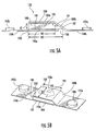
- Figure 5A is a side view of a sensor according to other embodiments of the present invention.
- Figure 5B is a top perspective view of the sensor of Figure 5A .
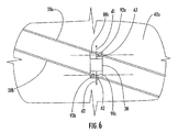
- Figure 6 is a greatly enlarged gage view of a sensor and attached leads for the roll of Figure 1 according to some embodiments of the present invention.
- the roll 20 includes a cylindrical core 22 (see Figure 2 ) and a cover 24 (typically formed of one or more polymeric materials) that encircles the core 22.
- a sensing system 26 for sensing an operating parameter, such as pressure or temperature includes a pair of electrical leads 28a, 28b and a plurality of sensors 30, each of which is at least partially embedded in the cover 24.
- a sensor being "embedded” in the cover means that the sensor is entirely contained within the cover, and a sensor being “embedded” in a particular layer or set of layers of the cover means that the sensor is entirely contained within that layer or set of layers.
- the sensing system 26 also includes a processor 32 that processes signals produced by the sensors 30.
- the core 22 is typically formed of a metallic material, such as steel or cast iron.
- the core 22 can be solid or hollow, and if hollow may include devices that can vary pressure or roll profile.
- the cover 24 can take any form and can be formed of any polymeric and/or elastomeric material recognized by those skilled in this art to be suitable for use with a roll.
- Exemplary materials include natural rubber, synthetic rubbers such as neoprene, styrene-butadiene (SBR), nitrile rubber, chlorosulfonated polyethylene (“CSPE” - also known under the trade name HYPALON), EDPM (the name given to an ethylene-propylene terpolymer formed of ethylene-propylene diene monomer), epoxy, and polyurethane.
- SBR styrene-butadiene
- CSPE chlorosulfonated polyethylene
- EDPM the name given to an ethylene-propylene terpolymer formed of ethylene-propylene diene monomer
- epoxy and polyurethane.
- the cover 24 may also include reinforcing and filler materials, additives, and the like. Exemplary additional materials are discussed
- the cover 24 will comprise multiple layers.
- Figures 2 and 3 illustrate the application of an inner base layer 42a, an outer base layer 42b and a topstock layer 70; additional layers, such as a "tie-in" layer between the outer base and topstock layers 42b, 70 and an adhesive layer between the core 22 and the inner base layer 42a, may also be included.
- the sensors 30 of the sensing system 26 are suitable for detecting an operating parameter of the roll 20, such as pressure.
- the sensors 30 typically include a substrate 80, electrodes 82, 84 attached to the top and bottom surfaces of the substrate, and a sheet of conductive material 88, 90 attached to each electrode.
- the sheets of conductive material 88, 90 extend away from the substrate in opposite directions.
- the substrate 80 comprises a piezoelectric material and the sensor is a piezoelectric sensor. Exemplary piezoelectric sensors are discussed in pending U.S. Patent Publication No. 2005/0261115 to Moore .
- Piezoelectric sensors can include any device that exhibits piezoelectricity when undergoing changes in pressure, temperature or other physical parameters. "Piezoelectricity” is defined as the generation of electricity or of electrical polarity in dielectric crystals subjected to mechanical or other stress, the magnitude of such electricity or electrical polarity being sufficient to distinguish it from electrical noise.
- Exemplary piezoelectric sensors include piezoelectric sensors formed of piezoelectric ceramic, such as PZT-type lead-zirgonate-titanate, quartz, synthetic quartz, tourmaline, gallium orthophosphate, CGG (Ca 3 Ga 2 Ge 4 O 14 ), lithium niobate, lithium tantalite, Rochelle salt, and lithium sulfate-monohydrate.
- the sensor material can have a Curie temperature of above 350°F (177°C), and in some instances 600°F (316°C) , which can enable accurate sensing at the temperatures often experienced by rolls in papermaking environments.
- the leads 28a, 28b of the sensing system 26 can be any signal-carrying members recognized by those skilled in this art as being suitable for the passage of electrical signals in a roll.
- the sheets of conductive material 88, 90 extend away from the substrate in opposite directions. The leads 28a, 28b contact the extended portions, sometimes called "wings.”
- the sensing system 26 includes a multiplexer 31 or other data collection device mounted to the end of the roll 20.
- the multiplexer 31 receives and collects signals from the sensors 30 and transmits them to a processer 32.
- the processor 32 is typically a personal computer or similar data exchange device, such as the distributive control system of a paper mill, that is operatively associated with the sensors 30 and that can process signals from the sensors 30 into useful, easily understood information.
- a wireless communication mode such as RF signaling
- Other alternative configurations include slip ring connectors that enable the signals to be transmitted from the sensors 30 to the processor 32. Suitable exemplary processing units are discussed in U.S. Patent Nos. 5,562,027 and 7,392,715 to Moore and 6,752,908 to Gustafson et al.
- the roll 20 can be manufactured in the manner described, for example, in pending U.S. Patent Publication No. 2005/0261115 , the disclosure of which is hereby incorporated herein in its entirety.
- the core 22 is covered with a portion of the cover 24 (such as the inner base layer 42a ).
- the inner base layer 42a can be applied with an extrusion nozzle (not shown), although the inner base layer 42a may be applied by other techniques known to those skilled in this art.
- the inner base layer 42a is formed of rubber or epoxy-based composite materials, and has a thickness of between about 0.030 and 0.350 inches (between about 0.76 and 9 mm).
- the leads 28a, 28b and sensors 30 of the sensor system 26 are installed ( Figure 2 ). Once the sensors 30 are in desired positions, they can be adhered in place. This may be carried out by any technique known to those skilled in this art; an exemplary technique is adhesive bonding.
- the outer base layer 42b is formed of rubber or epoxy-based composite materials and has a thickness of between about 0.030 and 0.350 inches (between about 0.76 and 9 mm), such that the sensors 30 are embedded in the base layer 42. Also, typically the outer base layer 42b will be formed of the same material as the inner base layer 42a.
- the present invention is intended to include rolls having covers that include only a base layer and top stock layer as well as rolls having covers with additional intermediate layers. Any intermediate layers would be applied over the outer base layer 42b prior to the application of the topstock layer 70.
- the topstock layer 70 is applied over the outer base layer 42b.
- the topstock layer 70 is typically formed of rubber or polyurethane, and may be applied via any technique known to those skilled in this art to be suitable for the application of a polymeric layer, although Figure 3 illustrates application via an extrusion nozzle 72.
- the topstock layer 70 is typically a polymeric material that has a hardness that is lower than that of the base layer 42.
- the topstock layer 70 is ordinarily between about 0.200 and 4.00 inches in thickness.
- Application of the top stock layer 70 is followed by curing, techniques for which are well-known to those skilled in this art and need not be described in detail herein.
- the completed roll 20 and cover 24 can then be used in a papermaking machine.
- the roll 20 is part of a nip press, wherein another roll or pressing device is positioned adjacent the roll 20 to form a nip through which a forming paper web can pass.
- another roll or pressing device is positioned adjacent the roll 20 to form a nip through which a forming paper web can pass.
- the sensing system 26 can provide pressure information for different axial locations along the cover 24, with each of the sensors 30 providing pressure information about a different axial location on the roll 20.
- the roll 20 and cover 24 rotate about the axis of the roll 20 at very high speeds.
- the sensor 30 will transmit a pulse generated by the pressure the mating roll exerts on the area of the cover 20 above the sensor 30.
- no sensor 30 is present in the nip, no significant pulses beyond the level of general noise are generated.
- each sensor 30 travels through the nip and provides pulses representative of the pressure at its corresponding location. Consequently, data in the form of pulses is generated by the sensors 30, transmitted along the leads 28a, 28b, and received in the multiplexer 31.
- 12-20 pulses are received per sensor 30; these individual pulses can be stored and processed into representative pressure signals for each sensor 30.
- the processor 32 Once the raw sensor data is collected, it is sent from the multiplexer 31 to the processor 32 for processing into an easily understood form, such as a pressure profile of the roll 20 along its length.
- FIGS 4A-4B illustrate in detail the sensor 30 according to some embodiments of the present invention.
- the sensor 30 includes the substrate 80.
- the substrate 80 is a piezoelectric material.
- the substrate 80 typically has a width W1 between about 2 mm and about 20 mm, a depth D1 between about 2 mm and about 20 mm, and a thickness t1 between about 0.5 mm and about 5 mm.
- the first electrode 82 overlies the top surface of the substrate 80 and the second electrode 84 underlies the bottom surface of the substrate 80.
- the electrodes 82, 84 typically have thicknesses of less than about 0.05 mm (0.002 inches).
- the first electrode 82 overlies the entire width W1 of the substrate 80.
- the second electrode 84 underlies only a portion of the width W1 of the substrate 80, thereby forming a gap 86 adjacent the bottom surface and a side surface 87 of the substrate 80.
- the gap 86 typically has a width of between about 0.5 mm and about 5 mm and spans the entire depth D1 of the substrate 80.
- the top surface and the side surface 87 of the substrate 80 form a right angle.
- a top portion 88a of the first sheet of conductive material 88 is attached to the first electrode 82.
- the first sheet of conductive material 88 is bent and attached to the side surface 87 of the substrate 80, thereby forming a side portion 88b of the first sheet of conductive material 88.
- the first sheet of conductive material 88 is bent again to extend in a first direction away from the bottom of the substrate 80 , thereby forming an extended portion 88c of the first sheet of conductive material 88.
- the side portion 88b is attached to the side surface 87 of the substrate 80 by any technique known to those skilled in this art; an exemplary technique is adhesive bonding via the use of adhesive transfer tape manufactured by 3MTM.
- the first sheet of conductive material 88 is attached to the side surface 87 of the substrate 80, the first sheet 88 does not span an unsupported distance as it is extended away from the substrate 80. The likelihood of catastrophic failure of the first sheet of conductive material 88 is greatly reduced because it is fully supported along its length.
- a bottom portion 90a of the second sheet of conductive material 90 is attached to the second electrode 84.
- the second sheet of conductive material 90 is extended in a second direction away from the bottom of the substrate 80, thereby forming an extended portion 90c of the second sheet of conductive material 90.
- the second direction associated with the second sheet of conductive material 90 is opposite the first direction associated with the first sheet of conductive material 88.
- the extended portions 88c, 90c serve as "wings" which may contact the leads 28a, 28b, as described in more detail below.
- the bottom portion 90a of the second sheet of conductive material 90 is attached to the second electrode 84 such that the gap 86 is preserved.
- the gap 86 serves to electrically isolate the electrodes 82, 84 as well as the sheets of conductive material 88, 90.
- the sheets of conductive material 88, 90 typically have thicknesses between about 0.001 and about 0.1 inches (between about 0.025 mm and about 2.5 mm).
- the extended portions 88c, 90c typically extend a distance between about 2 mm and about 20 mm away from the bottom of the substrate 80.
- the sheets of conductive material 88, 90 may be copper or any other conductive material.
- the sensor 30 includes lead mounting locations 92a, 92b, which may serve as connection points for the leads 28a, 28b.
- the first lead mounting location 92a is located on the extended portion 88c of the first sheet of conductive material 88 and the second lead mounting location 92b is located on the extended portion 90c of the second sheet of conductive material 90.
- the lead mounting locations 92a, 92b may be offset such the first lead mounting location 92a is positioned diagonally opposite the second lead mounting location 92b.
- the lead mounting locations 92a, 92b are solder dots.
- the sensor 30 may include an indicator 94 to clearly indicate the polarity of the electrodes 82, 84 and the sheets of conductive material 88, 90.
- the indicator 94 may be affixed to or imprinted on the top portion 88a of the first sheet of conductive material 88 ( i.e ., on the top of the sensor 30 ).
- the indicator 94 is an arrow.
- FIGS 5A-5B illustrate a sensor 130 according to some embodiments of the present invention.
- the sensor 130 includes a substrate 180.
- the substrate 180 is a piezoelectric material.
- the substrate 180 typically has a width W2 between about 2 mm and about 20 mm at its top surface, a width W3 between about 3 mm and about 21 mm at its bottom surface, a depth D2 between about 2 mm and about 20 mm, and a thickness t2 between about 0.5 mm and about 5 mm.
- a first electrode 182 overlies the top surface of the substrate 180 and a second electrode 184 underlies the bottom surface of the substrate 180.
- the electrodes 182, 184 typically have thicknesses of less than about 0.05 mm (0.002 inches).
- the first electrode 182 overlies the entire width W2 of the substrate 180.
- the second electrode 184 underlies only a portion of the width W3 of the substrate 180, thereby forming a gap 186 adjacent the bottom surface and a side surface 187 of the substrate 180.
- the gap 186 typically has a width of between about 0.5 mm and about 5 mm and spans the entire depth D2 of the substrate 180.
- the side surface 187 of the substrate 180 is sloped.
- the top surface and the side surface 187 of the substrate 180 form an obtuse angle A1.
- the obtuse angle A1 is typically between about 120 degrees and about 150 degrees. In some embodiments, the obtuse angle A1 is about 135 degrees.
- a top portion 188a of a first sheet of conductive material 188 is attached to the first electrode 182.
- the first sheet of conductive material 188 is bent and attached to the side surface 187 of the substrate 180, thereby forming a side portion 188b of the first sheet of conductive material 188.
- the first sheet of conductive material 188 is bent again to extend in a first direction away from the bottom of the substrate 180, thereby forming an extended portion 188c of the first sheet of conductive material 188.
- the side portion 188b is attached to the side surface 187 of the substrate 180 by any technique known to those skilled in this art; an exemplary technique is adhesive bonding via the use of adhesive transfer tape manufactured by 3MTM.
- the first sheet of conductive material 188 is attached to the side surface 187 of the substrate 180, the first sheet 188 does not span an unsupported distance as it is extended away from the substrate 180.
- the likelihood of catastrophic failure of the first sheet of conductive material 188 is greatly reduced because it is fully supported along its length.
- the sloped side surface 187 of the substrate 180 may offer additional advantages.
- the first sheet of conductive material 188 can be bent in a more gentle fashion ( i.e., it does not have to be bent at a right angle in two locations). Also, it is less likely that the first sheet of conductive material 188 will become detached from the sloped side surface 187 of the substrate 180.
- a bottom portion 190a of a second sheet of conductive material 190 is attached to the second electrode 184.
- the second sheet of conductive material 190 is extended in a second direction away from the bottom of the substrate 180, thereby forming an extended portion 190c of the second sheet of conductive material 190.
- the second direction associated with the second sheet of conductive material 190 is opposite the first direction associated with the first sheet of conductive material 188.
- the extended portions 188c, 190c serve as "wings" which may contact the leads 28a, 28b, as described in more detail below.
- the bottom portion 190a of the second sheet of conductive material 190 is attached to the second electrode 184 such that the gap 186 is preserved.
- the gap 186 serves to electrically isolate the electrodes 182, 184 as well as the sheets of conductive material 188, 190.
- the sheets of conductive material 188, 190 typically have thicknesses between about 0.001 and about 0.1 inches (between about 0.025mm and about 2.5mm).
- the extended portions 188c, 190c typically extend a distance between about 2 mm and about 20 mm away from the bottom surface of the substrate 180.
- the sheets of conductive material 188,190 may be copper or any other conductive material.
- the sensor 130 includes lead mounting locations 192a , 192b, which may serve as connection points for the leads 28a, 28b .
- the first lead mounting location 192a is located on the extended portion 188c of the first sheet of conductive material 188 and the second lead mounting location 192b is located on the extended portion 190c of the second sheet of conductive material 190.
- the lead mounting locations 192a, 192b may be offset such the first lead mounting location 192a is positioned diagonally opposite the second lead mounting location 192b.
- the lead mounting locations 192a, 192b are solder dots.
- the sensor 130 may include an indicator 194 to clearly indicate the polarity of the electrodes 182, 184 and the sheets of conductive material 188, 190.
- the indicator 194 may be affixed to or imprinted on the top portion 188a of the first sheet of conductive material 188 ( i . e ., on the top of the sensor 130).
- the indicator 194 is an arrow.
- the leads 28a, 28b may contact the sensor 30 at the extended portions 88c, 90c of the sheets of conductive material 88, 90.
- the leads 28a, 28b may form an oblique angle A2 with the first and second directions d1, d2 associated with the extended portions 88c, 90c.
- the leads 28a, 28b may form a right angle with the first and second directions d1, d2 associated with the extended portions 88c, 90c.
- the leads 28a, 28b may only contact diagonally opposite corners of the extended portions 88c, 90c.
- the angle A2 may be selected so that contact between the leads 28a, 28b and the sheets of conductive material 88, 90 is minimized.
- the oblique angle A2 is typically between about 1 degree and about 80 degrees. In some embodiments, the oblique angle A2 is between about 20 degrees and about 60 degrees.
- the sensor 30 may include lead mounting locations 92a, 92b on the extended portions 88c, 90c of the sheets of conductive material 88, 90.
- the lead mounting locations 92a, 92b may be offset such that they are positioned diagonally opposite each other. In this configuration, the lead mounting locations 92a, 92b are positioned to accept leads 28a, 28b that form the oblique angle A2 with the first and second directions d1, d2 associated with the extended portions 88c, 90c.
- the lead mounting locations 92a, 92b are solder dots.
- the leads 28a, 28b may overlie the extended portions 88c, 90c of the sheets of conductive material 88, 90. In some other embodiments, the leads 28a, 28b may underlie the extended portions 88c, 90c. In still other embodiments, one of the leads 28a, 28b may overlie one of the extended portions 88c, 90c and the other of the leads 28a, 28b may underlie the other of the extended portions 88c, 90c.
- the senor 130 may replace the sensor 30.
Landscapes
- Chemical & Material Sciences (AREA)
- Analytical Chemistry (AREA)
- Physics & Mathematics (AREA)
- General Physics & Mathematics (AREA)
- Force Measurement Appropriate To Specific Purposes (AREA)
- Paper (AREA)
- Rolls And Other Rotary Bodies (AREA)
- Press Drives And Press Lines (AREA)
- Measurement Of Length, Angles, Or The Like Using Electric Or Magnetic Means (AREA)
Description
- The present invention relates generally to to rolls for papermaking.
- In a typical papermaking process, a water slurry, or suspension, of cellulosic fibers (known as the paper "stock") is fed onto the top of the upper run of an endless belt of woven wire and/or synthetic material that travels between two or more rolls. The belt, often referred to as a "forming fabric," provides a papermaking surface on the upper surface of its upper run which operates as a filter to separate the cellulosic fibers of the paper stock from the aqueous medium, thereby forming a wet paper web. The aqueous medium drains through mesh openings of the forming fabric, known as drainage holes, by gravity or vacuum located on the lower surface of the upper run (i.e., the "machine side") of the fabric.
- After leaving the forming section, the paper web is transferred to a press section of the paper machine, where it is passed through the nips of one or more presses (often roller presses) covered with another fabric, typically referred to as a "press felt." Pressure from the presses removes additional moisture from the web; the moisture removal is often enhanced by the presence of a "batt" layer of the press felt. The paper is then transferred to a dryer section for further moisture removal. After drying, the paper is ready for secondary processing and packaging.
- Cylindrical rolls are typically utilized in different sections of a papermaking machine, such as the press section. Such rolls reside and operate in demanding environments in which they can be exposed to high dynamic loads and temperatures and aggressive or corrosive chemical agents. As an example, in a typical paper mill, rolls are used not only for transporting the fibrous web sheet between processing stations, but also, in the case of press section and calender rolls, for processing the web sheet itself into paper.
- Typically rolls used in papermaking are constructed with the location within the papermaking machine in mind, as rolls residing in different positions within the papermaking machines are required to perform different functions. Because papermaking rolls can have many different performance demands, and because replacing an entire metallic roll can be quite expensive, many papermaking rolls include a polymeric cover that surrounds the circumferential surface of a typically metallic core. By varying the material employed in the cover, the cover designer can provide the roll with different performance characteristics as the papermaking application demands. Also, repairing, regrinding or replacing a cover over a metallic roll can be considerably less expensive than the replacement of an entire metallic roll. Exemplary polymeric materials for covers include natural rubber, synthetic rubbers such as neoprene, styrene-butadiene (SBR), nitrile rubber, chlorosulfonated polyethylene ("CSPE" - also known under the trade name HYPALON® from DuPont), EDPM (the name given to an ethylene-propylene terpolymer formed of ethylene-propylene diene monomer), polyurethane, thermoset composites, and thermoplastic composites.
- In many instances, the roll cover will include at least two distinct layers: a base layer that overlies the core and provides a bond thereto; and a topstock layer that overlies and bonds to the base layer and serves the outer surface of the roll (some rolls will also include an intermediate "tie-in" layer sandwiched by the base and top stock layers). The layers for these materials are typically selected to provide the cover with a prescribed set of physical properties for operation. These can include the requisite strength, elastic modulus, and resistance to elevated temperature, water and harsh chemicals to withstand the papermaking environment. In addition, covers are typically designed to have a predetermined surface hardness that is appropriate for the process they are to perform, and they typically require that the paper sheet "release" from the cover without damage to the paper sheet. Also, in order to be economical, the cover should be abrasion- and wear-resistant.
- As the paper web is conveyed through a papermaking machine, it can be very important to understand the pressure profile experienced by the paper web. Variations in pressure can impact the amount of water drained from the web, which can affect the ultimate sheet moisture content, thickness, and other properties. The magnitude of pressure applied with a roll can, therefore, impact the quality of paper produced with the paper machine.
- It is known to include pressure and/or temperature sensors in the cover of an industrial roll. For example,
U. S. Patent No. 5,699,729 to Moschel et al. describes a roll with a helically-disposed leads that includes a plurality of pressure sensors embedded in the polymeric cover of the roll. The sensors are helically disposed in order to provide pressure readings at different axial locations along the length of the roll. Typically the sensors are connected to two leads which transmit sensor signals to a processor that processes the signals and provides pressure and position information. - The sensors typically include a substrate, such as a piezoelectric material, with electrodes attached to its top and bottom surfaces. Sheets of conductive material are attached to the electrodes and extended away from the substrate in opposite directions. The extended portions of conductive material (sometimes called "wings") serve as connection points for the leads. The two wings lie in substantially the same plane such that the sensor can lay flat. One wing is formed by extending the sheet attached to the bottom electrode directly away from the substrate. However, to form the other wing, the sheet attached to the top electrode is cantilevered from the top surface of the electrode and is deflected "down" to the level of the bottom wing. As a result, this sheet spans an unsupported distance and is susceptible to catastrophic failure at or near this unsupported section. This is especially the case during operation when the roll is exposed to high dynamic loads and temperatures and aggressive or corrosive chemical agents.
US 2005/026 1115 A1 discloses a papermaking roll according to the preamble of claim 1. - The present invention can address some of the issues raised by prior industrial rolls. As a first aspect, embodiments of the present invention are directed to a papermaking roll, comprising: a substantially cylindrical core having an outer surface and an internal lumen; a polymeric cover circumferentially overlying the core outer surface; and a sensing system comprising: a plurality of piezoelectric sensors at least partially embedded in the cover, the sensors configured to sense an operating parameter of the roll and provide signals related to the operating parameter; and a processor operatively associated with the sensors that processes signals provided by the sensors; characterized in that each of the plurality of sensors comprises: a substrate comprising a piezoelectric material, the substrate having a top surface, a bottom surface, and a side surface; a first electrode overlying the top surface of the substrate and a second electrode underlying only a portion of the bottom surface of the substrate, thereby forming a gap adjacent the bottom surface and a side surface of the substrate; a first sheet of conductive material attached to the first electrode and the side surface of the substrate and extended in a first direction away from the bottom surface of the substrate; and a second sheet of conductive material attached to the second electrode and extended in a second direction away from the bottom surface of the substrate, the second direction being opposite the first direction.
-
Figure 1 is a gage view of a roll and detecting system of the present invention. -
Figure 2 is a gage perspective view of the outer base layer being applied over the inner base layer, cables and sensors of the roll ofFigure 1 . -
Figure 3 is a gage perspective view of the topstock layer being applied over the outer base layer ofFigure 2 . -
Figure 4A is a side view of a sensor according to some embodiments of the present invention. -
Figure 4B is a top perspective view of the sensor ofFigure 4A . -
Figure 5A is a side view of a sensor according to other embodiments of the present invention. -
Figure 5B is a top perspective view of the sensor ofFigure 5A . -
Figure 6 is a greatly enlarged gage view of a sensor and attached leads for the roll ofFigure 1 according to some embodiments of the present invention. - The present invention will be described more particularly hereinafter with reference to the accompanying drawings. The invention is not intended to be limited to the illustrated embodiments; rather, these embodiments are intended to fully and completely disclose the invention to those skilled in this art. In the drawings, like numbers refer to like elements throughout. Thicknesses and dimensions of some components may be exaggerated for clarity.
- Well-known functions or constructions may not be described in detail for brevity and/or clarity.
- Referring now to the figures, a roll, designated broadly at 20, is illustrated in
Figure 1 . Theroll 20 includes a cylindrical core 22 (seeFigure 2 ) and a cover 24 (typically formed of one or more polymeric materials) that encircles thecore 22. Asensing system 26 for sensing an operating parameter, such as pressure or temperature, includes a pair ofelectrical leads sensors 30, each of which is at least partially embedded in thecover 24. As used herein, a sensor being "embedded" in the cover means that the sensor is entirely contained within the cover, and a sensor being "embedded" in a particular layer or set of layers of the cover means that the sensor is entirely contained within that layer or set of layers. Thesensing system 26 also includes aprocessor 32 that processes signals produced by thesensors 30. - The
core 22 is typically formed of a metallic material, such as steel or cast iron. Thecore 22 can be solid or hollow, and if hollow may include devices that can vary pressure or roll profile. - The
cover 24 can take any form and can be formed of any polymeric and/or elastomeric material recognized by those skilled in this art to be suitable for use with a roll. Exemplary materials include natural rubber, synthetic rubbers such as neoprene, styrene-butadiene (SBR), nitrile rubber, chlorosulfonated polyethylene ("CSPE" - also known under the trade name HYPALON), EDPM (the name given to an ethylene-propylene terpolymer formed of ethylene-propylene diene monomer), epoxy, and polyurethane. Thecover 24 may also include reinforcing and filler materials, additives, and the like. Exemplary additional materials are discussed inU.S. Patent Nos. 6,328,681 to Stephens ,6,375,602 to Jones , and6,981,935 to Gustafson . - In many instances, the
cover 24 will comprise multiple layers.Figures 2 and 3 illustrate the application of aninner base layer 42a, anouter base layer 42b and atopstock layer 70; additional layers, such as a "tie-in" layer between the outer base andtopstock layers inner base layer 42a, may also be included. - Referring again to
Figure 1 and toFigures 4A-4B , thesensors 30 of thesensing system 26 are suitable for detecting an operating parameter of theroll 20, such as pressure. As discussed in more detail below, thesensors 30 typically include asubstrate 80,electrodes conductive material conductive material substrate 80 comprises a piezoelectric material and the sensor is a piezoelectric sensor. Exemplary piezoelectric sensors are discussed in pendingU.S. Patent Publication No. 2005/0261115 to Moore . Piezoelectric sensors can include any device that exhibits piezoelectricity when undergoing changes in pressure, temperature or other physical parameters. "Piezoelectricity" is defined as the generation of electricity or of electrical polarity in dielectric crystals subjected to mechanical or other stress, the magnitude of such electricity or electrical polarity being sufficient to distinguish it from electrical noise. Exemplary piezoelectric sensors include piezoelectric sensors formed of piezoelectric ceramic, such as PZT-type lead-zirgonate-titanate, quartz, synthetic quartz, tourmaline, gallium orthophosphate, CGG (Ca3Ga2Ge4O14), lithium niobate, lithium tantalite, Rochelle salt, and lithium sulfate-monohydrate. In particular, the sensor material can have a Curie temperature of above 350°F (177°C), and in some instances 600°F (316°C) , which can enable accurate sensing at the temperatures often experienced by rolls in papermaking environments. - Still referring to
Figure 1 , theleads sensing system 26 can be any signal-carrying members recognized by those skilled in this art as being suitable for the passage of electrical signals in a roll. As discussed above, the sheets ofconductive material leads - The
sensing system 26 includes amultiplexer 31 or other data collection device mounted to the end of theroll 20. Themultiplexer 31 receives and collects signals from thesensors 30 and transmits them to aprocesser 32. Theprocessor 32 is typically a personal computer or similar data exchange device, such as the distributive control system of a paper mill, that is operatively associated with thesensors 30 and that can process signals from thesensors 30 into useful, easily understood information. In some embodiments, a wireless communication mode, such as RF signaling, is used to transmit the data collected from thesensors 30 from themultiplexer 31 to theprocessor 32. Other alternative configurations include slip ring connectors that enable the signals to be transmitted from thesensors 30 to theprocessor 32. Suitable exemplary processing units are discussed inU.S. Patent Nos. 5,562,027 and7,392,715 to Moore and6,752,908 to Gustafson et al. - The
roll 20 can be manufactured in the manner described, for example, in pendingU.S. Patent Publication No. 2005/0261115 , the disclosure of which is hereby incorporated herein in its entirety. In this method, initially the core 22 is covered with a portion of the cover 24 (such as theinner base layer 42a). Theinner base layer 42a can be applied with an extrusion nozzle (not shown), although theinner base layer 42a may be applied by other techniques known to those skilled in this art. Typically theinner base layer 42a is formed of rubber or epoxy-based composite materials, and has a thickness of between about 0.030 and 0.350 inches (between about 0.76 and 9 mm). - After the formation of the
inner base layer 42a, theleads sensors 30 of thesensor system 26 are installed (Figure 2 ). Once thesensors 30 are in desired positions, they can be adhered in place. This may be carried out by any technique known to those skilled in this art; an exemplary technique is adhesive bonding. - Referring again to
Figure 2 , once thesensors 30 and leads 28a, 28b have been positioned and affixed to theinner base layer 42a, the remainder of the base layer 42 (i.e., theouter base layer 42b) is applied.Figure 2 illustrates the application of theouter base layer 42b via anextrusion nozzle 52, although those skilled in this art will appreciate that the application of theouter base layer 42b can be carried out by any technique recognized as being suitable for such application. In a typical roll, theouter base layer 42b is formed of rubber or epoxy-based composite materials and has a thickness of between about 0.030 and 0.350 inches (between about 0.76 and 9 mm), such that thesensors 30 are embedded in the base layer 42. Also, typically theouter base layer 42b will be formed of the same material as theinner base layer 42a. - As noted above, the present invention is intended to include rolls having covers that include only a base layer and top stock layer as well as rolls having covers with additional intermediate layers. Any intermediate layers would be applied over the
outer base layer 42b prior to the application of thetopstock layer 70. - Turning now to
Figure 3 , thetopstock layer 70 is applied over theouter base layer 42b. Thetopstock layer 70 is typically formed of rubber or polyurethane, and may be applied via any technique known to those skilled in this art to be suitable for the application of a polymeric layer, althoughFigure 3 illustrates application via anextrusion nozzle 72. Thetopstock layer 70 is typically a polymeric material that has a hardness that is lower than that of the base layer 42. Thetopstock layer 70 is ordinarily between about 0.200 and 4.00 inches in thickness. Application of thetop stock layer 70 is followed by curing, techniques for which are well-known to those skilled in this art and need not be described in detail herein. - The completed
roll 20 and cover 24 can then be used in a papermaking machine. In some embodiments, theroll 20 is part of a nip press, wherein another roll or pressing device is positioned adjacent theroll 20 to form a nip through which a forming paper web can pass. In such environments, it can be important to monitor the pressure experienced by thecover 24, particularly in the nip area. Thesensing system 26 can provide pressure information for different axial locations along thecover 24, with each of thesensors 30 providing pressure information about a different axial location on theroll 20. - In operation, the
roll 20 and cover 24 rotate about the axis of theroll 20 at very high speeds. Each time one of thesensors 30 passes through the nip created by theroll 20 and a mating roll or press, thesensor 30 will transmit a pulse generated by the pressure the mating roll exerts on the area of thecover 20 above thesensor 30. When nosensor 30 is present in the nip, no significant pulses beyond the level of general noise are generated. Thus, as theroll 20 rotates, eachsensor 30 travels through the nip and provides pulses representative of the pressure at its corresponding location. Consequently, data in the form of pulses is generated by thesensors 30, transmitted along theleads multiplexer 31. In a typical data retrieval session, 12-20 pulses are received persensor 30; these individual pulses can be stored and processed into representative pressure signals for eachsensor 30. Once the raw sensor data is collected, it is sent from themultiplexer 31 to theprocessor 32 for processing into an easily understood form, such as a pressure profile of theroll 20 along its length. -
Figures 4A-4B illustrate in detail thesensor 30 according to some embodiments of the present invention. Thesensor 30 includes thesubstrate 80. Thesubstrate 80 is a piezoelectric material. Thesubstrate 80 typically has a width W1 between about 2 mm and about 20 mm, a depth D1 between about 2 mm and about 20 mm, and a thickness t1 between about 0.5 mm and about 5 mm. - The
first electrode 82 overlies the top surface of thesubstrate 80 and thesecond electrode 84 underlies the bottom surface of thesubstrate 80. Theelectrodes first electrode 82 overlies the entire width W1 of thesubstrate 80. Thesecond electrode 84 underlies only a portion of the width W1 of thesubstrate 80, thereby forming agap 86 adjacent the bottom surface and aside surface 87 of thesubstrate 80. Thegap 86 typically has a width of between about 0.5 mm and about 5 mm and spans the entire depth D1 of thesubstrate 80. In the illustrated embodiment, the top surface and theside surface 87 of thesubstrate 80 form a right angle. - A
top portion 88a of the first sheet ofconductive material 88 is attached to thefirst electrode 82. The first sheet ofconductive material 88 is bent and attached to theside surface 87 of thesubstrate 80, thereby forming aside portion 88b of the first sheet ofconductive material 88. The first sheet ofconductive material 88 is bent again to extend in a first direction away from the bottom of thesubstrate 80, thereby forming anextended portion 88c of the first sheet ofconductive material 88. Theside portion 88b is attached to theside surface 87 of thesubstrate 80 by any technique known to those skilled in this art; an exemplary technique is adhesive bonding via the use of adhesive transfer tape manufactured by 3M™. Because the first sheet ofconductive material 88 is attached to theside surface 87 of thesubstrate 80, thefirst sheet 88 does not span an unsupported distance as it is extended away from thesubstrate 80. The likelihood of catastrophic failure of the first sheet ofconductive material 88 is greatly reduced because it is fully supported along its length. - A
bottom portion 90a of the second sheet ofconductive material 90 is attached to thesecond electrode 84. The second sheet ofconductive material 90 is extended in a second direction away from the bottom of thesubstrate 80, thereby forming anextended portion 90c of the second sheet ofconductive material 90. The second direction associated with the second sheet ofconductive material 90 is opposite the first direction associated with the first sheet ofconductive material 88. In this regard, theextended portions leads - The
bottom portion 90a of the second sheet ofconductive material 90 is attached to thesecond electrode 84 such that thegap 86 is preserved. Thegap 86 serves to electrically isolate theelectrodes conductive material - The sheets of
conductive material extended portions substrate 80. The sheets ofconductive material - In some embodiments, the
sensor 30 includes lead mountinglocations leads lead mounting location 92a is located on theextended portion 88c of the first sheet ofconductive material 88 and the secondlead mounting location 92b is located on theextended portion 90c of the second sheet ofconductive material 90. As illustrated inFigure 4B , thelead mounting locations lead mounting location 92a is positioned diagonally opposite the secondlead mounting location 92b. In some embodiments, thelead mounting locations - As illustrated in
Figure 4B , thesensor 30 may include anindicator 94 to clearly indicate the polarity of theelectrodes conductive material indicator 94 may be affixed to or imprinted on thetop portion 88a of the first sheet of conductive material 88 (i.e., on the top of the sensor 30). In some embodiments, theindicator 94 is an arrow. -
Figures 5A-5B illustrate asensor 130 according to some embodiments of the present invention. Thesensor 130 includes asubstrate 180. Thesubstrate 180 is a piezoelectric material. Thesubstrate 180 typically has a width W2 between about 2 mm and about 20 mm at its top surface, a width W3 between about 3 mm and about 21 mm at its bottom surface, a depth D2 between about 2 mm and about 20 mm, and a thickness t2 between about 0.5 mm and about 5 mm. - A
first electrode 182 overlies the top surface of thesubstrate 180 and asecond electrode 184 underlies the bottom surface of thesubstrate 180. Theelectrodes first electrode 182 overlies the entire width W2 of thesubstrate 180. Thesecond electrode 184 underlies only a portion of the width W3 of thesubstrate 180, thereby forming agap 186 adjacent the bottom surface and aside surface 187 of thesubstrate 180. Thegap 186 typically has a width of between about 0.5 mm and about 5 mm and spans the entire depth D2 of thesubstrate 180. - As illustrated in
Figures 5A-5B , theside surface 187 of thesubstrate 180 is sloped. In this regard, the top surface and theside surface 187 of thesubstrate 180 form an obtuse angle A1. The obtuse angle A1 is typically between about 120 degrees and about 150 degrees. In some embodiments, the obtuse angle A1 is about 135 degrees. - A
top portion 188a of a first sheet ofconductive material 188 is attached to thefirst electrode 182. The first sheet ofconductive material 188 is bent and attached to theside surface 187 of thesubstrate 180, thereby forming aside portion 188b of the first sheet ofconductive material 188. The first sheet ofconductive material 188 is bent again to extend in a first direction away from the bottom of thesubstrate 180, thereby forming anextended portion 188c of the first sheet ofconductive material 188. Theside portion 188b is attached to theside surface 187 of thesubstrate 180 by any technique known to those skilled in this art; an exemplary technique is adhesive bonding via the use of adhesive transfer tape manufactured by 3M™. Because the first sheet ofconductive material 188 is attached to theside surface 187 of thesubstrate 180, thefirst sheet 188 does not span an unsupported distance as it is extended away from thesubstrate 180. The likelihood of catastrophic failure of the first sheet ofconductive material 188 is greatly reduced because it is fully supported along its length. The slopedside surface 187 of thesubstrate 180 may offer additional advantages. The first sheet ofconductive material 188 can be bent in a more gentle fashion (i.e., it does not have to be bent at a right angle in two locations). Also, it is less likely that the first sheet ofconductive material 188 will become detached from the slopedside surface 187 of thesubstrate 180. - A
bottom portion 190a of a second sheet ofconductive material 190 is attached to thesecond electrode 184. The second sheet ofconductive material 190 is extended in a second direction away from the bottom of thesubstrate 180, thereby forming anextended portion 190c of the second sheet ofconductive material 190. The second direction associated with the second sheet ofconductive material 190 is opposite the first direction associated with the first sheet ofconductive material 188. In this regard, theextended portions leads - The
bottom portion 190a of the second sheet ofconductive material 190 is attached to thesecond electrode 184 such that thegap 186 is preserved. Thegap 186 serves to electrically isolate theelectrodes conductive material - The sheets of
conductive material extended portions substrate 180. The sheets of conductive material 188,190 may be copper or any other conductive material. - In some embodiments, the
sensor 130 includes lead mountinglocations leads lead mounting location 192a is located on theextended portion 188c of the first sheet ofconductive material 188 and the secondlead mounting location 192b is located on theextended portion 190c of the second sheet ofconductive material 190. As illustrated inFigure 5B , thelead mounting locations lead mounting location 192a is positioned diagonally opposite the secondlead mounting location 192b. In some embodiments, thelead mounting locations - As illustrated in
Figure 5B , thesensor 130 may include anindicator 194 to clearly indicate the polarity of theelectrodes conductive material indicator 194 may be affixed to or imprinted on thetop portion 188a of the first sheet of conductive material 188 (i.e., on the top of the sensor 130). In some embodiments, theindicator 194 is an arrow. - Turning now to
Figure 6 , and as noted above, theleads sensor 30 at theextended portions conductive material Figure 6 , theleads extended portions leads extended portions - As illustrated in
Figure 6 , where theleads extended portions conductive material leads extended portions leads conductive material - In some embodiments, and as further illustrated in
Figure 6 , thesensor 30 may include lead mountinglocations extended portions conductive material lead mounting locations lead mounting locations leads extended portions lead mounting locations - As exemplified in
Figure 6 , theleads extended portions conductive material leads extended portions leads extended portions leads extended portions - Although the
sensor 30 is illustrated inFigure 6 , the sensor 130 (with correspondingextended portions conductive material locations sensor 30.
Claims (13)
- A papermaking roll (20), comprising:a substantially cylindrical core (22) having an outer surface and an internal lumen;a polymeric cover (24) circumferentially overlying the core outer surface; anda sensing system (26) comprising:a plurality of piezoelectric sensors (30, 130) at least partially embedded in the cover, the sensors configured to sense an operating parameter of the roll and provide signals related to the operating parameter; anda processor (32) operatively associated with the sensors that processes signals provided by the sensors;characterized in that each of the plurality of sensors comprises:a substrate (80, 180) comprising a piezoelectric material, the substrate having a top surface, a bottom surface, and a side surface;a first electrode (82, 182) overlying the top surface of the substrate and a second electrode (84, 184) underlying only a portion of the bottom surface of the substrate, thereby forming a gap (86, 186) adjacent the bottom surface and a side surface of the substrate;a first sheet of conductive material (88, 188) attached to the first electrode and the side surface of the substrate and extended in a first direction away from the bottom surface of the substrate; anda second sheet of conductive material (90, 190) attached to the second electrode and extended in a second direction away from the bottom surface of the substrate, the second direction being opposite the first direction.
- The roll as defined in Claim 1, wherein the top surface and the side surface of the substrate form a right angle.
- The roll as defined in Claim 1, wherein the top surface and the side surface of the substrate form an obtuse angle (A1).
- The roll as defined in any one of the preceding claims, wherein the sensing system further comprises electrical leads (28a, 28b) that interconnect each of the plurality of sensors.
- The roll as defined in any one of the preceding claims, wherein each of the plurality of sensors further comprises a first lead mounting location (92a, 192a) on the extended portion of the first sheet of conductive material and a second lead mounting location (92b, 192b) on the extended portion of the second sheet of conductive material.
- The roll as defined in Claim 5, wherein the sensing system further comprises electrical leads (28a, 28b) that interconnect each of the plurality of sensors at the lead mounting locations.
- The roll as defined in any one of Claims 5 and 6, wherein the lead mounting locations comprise solder dots.
- The roll as defined in any one of Claims 5-7, wherein the first lead mounting location is positioned diagonally opposite the second lead mounting location.
- The roll as defined in any one of Claims 4-8, wherein the electrical leads form an oblique angle (A2) between about 1 degree and about 80 degrees with the first and second directions.
- The roll as defined in any one of the preceding claims, wherein the sensors are configured to sense pressure.
- The roll defined in any one of the preceding claims, wherein the sensors include an indicator (94, 194) to indicate the polarity of the electrodes and sheets of conductive material.
- The roll as defined in any one of the preceding claims, wherein the cover includes a base layer (42) that circumferentially overlies the core and a topstock layer (70) that circumferentially overlies the base layer, and wherein the sensors are embedded in the base layer.
- The roll as defined in Claim 12, wherein the topstock layer is formed of a material selected from the group consisting of rubber and polyurethane.
Applications Claiming Priority (2)
| Application Number | Priority Date | Filing Date | Title |
|---|---|---|---|
| US12/489,711 US8236141B2 (en) | 2009-06-23 | 2009-06-23 | Industrial roll with sensors having conformable conductive sheets |
| PCT/US2010/038581 WO2011005423A2 (en) | 2009-06-23 | 2010-06-15 | Industrial roll with sensors having conformable conductive sheets |
Publications (2)
| Publication Number | Publication Date |
|---|---|
| EP2379805A2 EP2379805A2 (en) | 2011-10-26 |
| EP2379805B1 true EP2379805B1 (en) | 2012-12-05 |
Family
ID=43302669
Family Applications (1)
| Application Number | Title | Priority Date | Filing Date |
|---|---|---|---|
| EP10731856A Active EP2379805B1 (en) | 2009-06-23 | 2010-06-15 | Industrial roll with sensors having conformable conductive sheets |
Country Status (7)
| Country | Link |
|---|---|
| US (1) | US8236141B2 (en) |
| EP (1) | EP2379805B1 (en) |
| JP (1) | JP5181062B2 (en) |
| CN (1) | CN102264981B (en) |
| BR (1) | BRPI1006976A2 (en) |
| CA (1) | CA2749697C (en) |
| WO (1) | WO2011005423A2 (en) |
Families Citing this family (17)
| Publication number | Priority date | Publication date | Assignee | Title |
|---|---|---|---|---|
| US8475347B2 (en) * | 2010-06-04 | 2013-07-02 | Stowe Woodward Licensco, Llc | Industrial roll with multiple sensor arrays |
| AU2013209881B2 (en) | 2012-01-17 | 2015-04-30 | Stowe Woodward Licensco, Llc | System and method of determining the angular position of a rotating roll |
| EP2679721A1 (en) | 2012-06-26 | 2014-01-01 | Metso Paper Inc. | Sensor arrangement and a roll of a fiber web production line |
| US9540769B2 (en) | 2013-03-11 | 2017-01-10 | International Paper Company | Method and apparatus for measuring and removing rotational variability from a nip pressure profile of a covered roll of a nip press |
| US10378980B2 (en) | 2014-05-02 | 2019-08-13 | International Paper Company | Method and system associated with a sensing roll and a mating roll for collecting roll data |
| US9797788B2 (en) | 2014-05-02 | 2017-10-24 | International Paper Company | Method and system associated with a sensing roll including pluralities of sensors and a mating roll for collecting roll data |
| US9804044B2 (en) | 2014-05-02 | 2017-10-31 | International Paper Company | Method and system associated with a sensing roll and a mating roll for collecting data including first and second sensor arrays |
| US9650744B2 (en) | 2014-09-12 | 2017-05-16 | Stowe Woodward Licensco Llc | Suction roll with sensors for detecting operational parameters |
| DE102014115023A1 (en) * | 2014-10-16 | 2016-04-21 | Bwg Bergwerk- Und Walzwerk-Maschinenbau Gmbh | Flatness measuring roll with measuring bar in strip running direction |
| US9863827B2 (en) | 2015-06-10 | 2018-01-09 | International Paper Company | Monitoring machine wires and felts |
| US9677225B2 (en) | 2015-06-10 | 2017-06-13 | International Paper Company | Monitoring applicator rods |
| US9816232B2 (en) | 2015-06-10 | 2017-11-14 | International Paper Company | Monitoring upstream machine wires and felts |
| US9696226B2 (en) | 2015-06-10 | 2017-07-04 | International Paper Company | Count-based monitoring machine wires and felts |
| US9534970B1 (en) | 2015-06-10 | 2017-01-03 | International Paper Company | Monitoring oscillating components |
| US10370795B2 (en) | 2015-06-10 | 2019-08-06 | International Paper Company | Monitoring applicator rods and applicator rod nips |
| CN108699771B (en) | 2016-04-26 | 2019-12-03 | 斯托·伍德沃德许可有限责任公司 | Vacuum roll with through hole and blind drill pattern for improved land distance |
| FI130099B (en) * | 2022-02-16 | 2023-02-17 | Etteplan Oyj | A sensor device for detecting deformation of nip rolls |
Family Cites Families (65)
| Publication number | Priority date | Publication date | Assignee | Title |
|---|---|---|---|---|
| DE863133C (en) | 1951-07-19 | 1953-01-15 | Schoppe & Faeser Feinmechanik | Temperature sensor |
| US2815907A (en) * | 1955-01-20 | 1957-12-10 | Cons Electrodynamics Corp | Tape transport system |
| US3308476A (en) * | 1964-01-21 | 1967-03-07 | Kleesattel Claus | Resonant sensing devices |
| US3562883A (en) * | 1968-06-26 | 1971-02-16 | Shogo Kobayashi | Suction press roll for papermaking |
| US3665650A (en) * | 1969-10-22 | 1972-05-30 | Murray Way Corp | Abrasive belt control apparatus and method |
| US4016756A (en) * | 1972-06-08 | 1977-04-12 | Beloit Corporation | Nip load sensing device |
| US3962911A (en) * | 1974-11-21 | 1976-06-15 | Beloit Corporation | Method and apparatus for coupling signals from a rotating device with end shafts exposed |
| DE2837913C2 (en) * | 1978-08-31 | 1982-10-21 | ER-WE-PA Maschinenfabrik und Eisengießerei GmbH, 4006 Erkrath | Roller with controllable deflection, in particular for machines for producing and processing webs made of paper or plastic |
| DE3117398A1 (en) * | 1981-05-02 | 1982-11-18 | Escher Wyss AG, Zürich | "ASSEMBLY WITH A DEFLECTION ROLLER AND ASSOCIATED CONTROLLER" |
| US4366025A (en) * | 1981-06-04 | 1982-12-28 | Beloit Corporation | Suction press roll |
| DE3131799C2 (en) * | 1981-08-12 | 1984-08-30 | Kleinewefers Gmbh, 4150 Krefeld | Roller press for paper and similar webs, in particular calenders |
| US4445349A (en) * | 1981-11-17 | 1984-05-01 | White Consolidated Industries, Inc. | Variable crown roll shape control systems |
| DE3516535A1 (en) * | 1985-05-08 | 1986-11-13 | Kleinewefers Gmbh | ROLLER UNIT WITH BENT CONTROLLABLE AND TEMPERATURE ROLLER |
| US4871908A (en) * | 1986-02-03 | 1989-10-03 | The Babcock & Wilcox Company | Overload protection for fiber optic microbend sensor |
| CA1284681C (en) * | 1986-07-09 | 1991-06-04 | Alcan International Limited | Methods and apparatus for the detection and correction of roll eccentricity in rolling mills |
| DE3767476D1 (en) * | 1987-05-09 | 1991-02-21 | Kleinewefers Gmbh | METHOD FOR OPERATING A ROLLING MACHINE AND CONTROL ARRANGEMENT FOR CARRYING OUT THIS METHOD. |
| DE3736999A1 (en) * | 1987-10-31 | 1989-06-01 | Rosenstock Hans G | METHOD FOR MEASURING THE ROLLING FORCE ON ROLLING MILLS |
| US4898012A (en) * | 1988-04-22 | 1990-02-06 | United Engineering, Inc. | Roll bite gauge and profile measurement system for rolling mills |
| US5048353A (en) * | 1990-03-01 | 1991-09-17 | Beloit Corporation | Method and apparatus for roll profile measurement |
| US6006100A (en) * | 1990-05-25 | 1999-12-21 | Norand Corporation | Multi-level, hierarchical radio-frequency communication system |
| US5086220A (en) * | 1991-02-05 | 1992-02-04 | The Babcock & Wilcox Company | Radiation imaging fiber optic temperature distribution monitor |
| US5739626A (en) * | 1991-04-27 | 1998-04-14 | Ngk Spark Plug Co., Ltd. | Piezoelectric sensor |
| FI86771C (en) * | 1991-10-14 | 1992-10-12 | Valmet Paper Machinery Inc | Method and apparatus for measuring the nip power and / or pressure of a nip formed by a rotating roller or belt used in the manufacture of paper |
| FI89308C (en) * | 1992-09-16 | 1993-09-10 | Valmet Paper Machinery Inc | FOERFARANDE OCH ANORDNING FOER MAETNING AV NYPKRAFTEN OCH / ELLER -TRYCKET AV ETT NYP SOM BILDAS AV EN ROTERANDE VALS ELLER ETT BAND SOM ANVAENDS VID FRAMSTAELLNING AV PAPPER |
| JP3172286B2 (en) * | 1992-10-26 | 2001-06-04 | 三洋電機株式会社 | Pressing force measuring device in electronic component mounting device |
| JP3236098B2 (en) * | 1992-12-28 | 2001-12-04 | オリンパス光学工業株式会社 | Pressure sensor |
| FI93755C (en) * | 1993-07-07 | 1995-05-26 | Valmet Paper Machinery Inc | Suction roll of a paper machine |
| US5535240A (en) * | 1993-10-29 | 1996-07-09 | Airnet Communications Corporation | Transceiver apparatus employing wideband FFT channelizer and inverse FFT combiner for multichannel communication network |
| US5592875A (en) * | 1994-09-16 | 1997-01-14 | Stowe Woodward Licensco, Inc. | Roll having means for determining pressure distribution |
| US5562027A (en) * | 1995-02-16 | 1996-10-08 | Stowe Woodward Licensco, Inc. | Dynamic nip pressure and temperature sensing system |
| DE29506620U1 (en) * | 1995-04-19 | 1995-06-08 | Voith Sulzer Papiermaschinen GmbH, 89522 Heidenheim | Suction roll |
| FR2733591B1 (en) | 1995-04-26 | 1997-06-13 | Honeywell | PRESSURE SENSITIVE OPTICAL DEVICE AND PRESENCE DETECTION FLOOR |
| US5684871A (en) * | 1995-05-02 | 1997-11-04 | Apple Computer, Inc. | Method and apparatus for multi-mode infrared data transmission |
| US5799533A (en) * | 1995-05-12 | 1998-09-01 | Director-General Of Agency Of Industrial Science And Technology | Distributed pressure sensor and method for manufacturing the same |
| CA2177803A1 (en) * | 1995-06-01 | 1996-12-02 | Robert H. Moore | Nip pressure sensing system |
| US5684912A (en) * | 1995-10-18 | 1997-11-04 | Fico, Inc. | Optical fiber signal attenuator |
| JPH09219932A (en) * | 1996-02-13 | 1997-08-19 | Alps Electric Co Ltd | Wireless device charger |
| DE19647919A1 (en) * | 1996-11-20 | 1998-05-28 | Voith Sulzer Papiermasch Gmbh | Moving paper or cardboard web guide |
| US6341522B1 (en) * | 1996-12-13 | 2002-01-29 | Measurex Corporation | Water weight sensor array imbedded in a sheetmaking machine roll |
| FR2769379B1 (en) | 1997-10-03 | 2000-02-11 | France Telecom | DEVICE FOR THE OPERATION AND MAINTENANCE OF FIBER OPTIC NETWORKS |
| US5947401A (en) * | 1997-10-14 | 1999-09-07 | Niccum; Richard E | Motion picture film platter assembly for theatres |
| US6568285B1 (en) * | 1998-02-19 | 2003-05-27 | Stowe Woodward Llc | Nip width sensing system and method |
| US6375602B1 (en) * | 1998-07-23 | 2002-04-23 | Sw Paper Inc. | Supercalendar roll with composite cover |
| CA2279609C (en) * | 1998-08-06 | 2007-05-01 | Voith Sulzer Papiertechnik Patent Gmbh | Device to actively weaken undesirable vibrations in a rotating roll; device for treatment of a material web; specifically a paper or cardboard web |
| US6328681B1 (en) * | 1999-01-21 | 2001-12-11 | Stowe Woodward Inc. | Elastomeric roll cover with ultra high molecular weight polyethylene filler |
| US6441904B1 (en) * | 1999-03-04 | 2002-08-27 | Metso Paper Automation Oy | Method and apparatus for measuring properties of a moving fiber web |
| JP2000275123A (en) * | 1999-03-25 | 2000-10-06 | Tokai Rubber Ind Ltd | Distribution sensor |
| DE19918699B4 (en) * | 1999-04-26 | 2008-03-27 | Betriebsforschungsinstitut VDEh - Institut für angewandte Forschung GmbH | Measuring roller for determining flatness deviations |
| DE19920133A1 (en) | 1999-05-03 | 2000-11-09 | Voith Sulzer Papiertech Patent | Measurement of nip force in pressure nip gap between two web press rollers, has roller mantle fitted with one or more piezo quartz units |
| US6284103B1 (en) * | 1999-07-21 | 2001-09-04 | Voith Sulzer Paper Technology North America, Inc. | Suction roll shell in a paper-making machine and method of manufacturing same |
| US6361483B1 (en) * | 1999-10-22 | 2002-03-26 | Morrison Berkshire, Inc. | System for controlling vibration of a dynamic surface |
| US6429421B1 (en) | 2000-01-21 | 2002-08-06 | Luna Innovations, Inc. | Flexible fiber optic microbend device, with interlocking flexible fibers, sensors, and method use |
| US6617764B2 (en) * | 2000-09-13 | 2003-09-09 | University Of Dayton | High temperature piezoelectric sensor |
| EP1361950A1 (en) * | 2001-02-22 | 2003-11-19 | Metso Paper, Inc. | Measurement method and system in the manufacture of paper or paperboard |
| US6752908B2 (en) * | 2001-06-01 | 2004-06-22 | Stowe Woodward, Llc | Shoe press belt with system for detecting operational parameters |
| FI113466B (en) | 2001-12-20 | 2004-04-30 | Metso Paper Inc | Method and apparatus for observing the edge of a web |
| US6981935B2 (en) * | 2002-09-12 | 2006-01-03 | Stowe Woodward, L.L.C. | Suction roll with sensors for detecting temperature and/or pressure |
| US6892563B2 (en) * | 2002-11-26 | 2005-05-17 | Stowe Woodward Llc | Calibration apparatus and method for roll covers with embedded sensors |
| US6874232B2 (en) * | 2003-05-21 | 2005-04-05 | Stowe Woodward, Llc | Method for forming cover for industrial roll |
| US7185537B2 (en) * | 2003-06-04 | 2007-03-06 | Metso Paper, Inc. | Nip and loading analysis system |
| DE10329430B4 (en) | 2003-07-01 | 2005-05-04 | Koenig & Bauer Ag | Roller with integrated pressure sensor |
| MXPA06013172A (en) * | 2004-05-14 | 2007-02-13 | Stowe Woodward Llc | Nip press sensing system including a sensor strip having sensor interface electronics associated therewith and methods of operating the same. |
| US20050261115A1 (en) * | 2004-05-14 | 2005-11-24 | Myers Bigel Sibley & Sajovec, P.A. | Industrial roll with piezoelectric sensors for detecting pressure |
| US7392715B2 (en) * | 2004-10-29 | 2008-07-01 | Stowe Woodward Ag | Wireless sensors in roll covers |
| US7572214B2 (en) * | 2005-05-04 | 2009-08-11 | Stowe Woodward L.L.C. | Suction roll with sensors for detecting operational parameters having apertures |
-
2009
- 2009-06-23 US US12/489,711 patent/US8236141B2/en active Active
-
2010
- 2010-06-15 EP EP10731856A patent/EP2379805B1/en active Active
- 2010-06-15 CA CA2749697A patent/CA2749697C/en active Active
- 2010-06-15 BR BRPI1006976A patent/BRPI1006976A2/en not_active IP Right Cessation
- 2010-06-15 WO PCT/US2010/038581 patent/WO2011005423A2/en not_active Ceased
- 2010-06-15 JP JP2011549359A patent/JP5181062B2/en active Active
- 2010-06-15 CN CN201080003709.7A patent/CN102264981B/en active Active
Also Published As
| Publication number | Publication date |
|---|---|
| US20100319868A1 (en) | 2010-12-23 |
| JP5181062B2 (en) | 2013-04-10 |
| BRPI1006976A2 (en) | 2016-04-12 |
| WO2011005423A2 (en) | 2011-01-13 |
| CN102264981A (en) | 2011-11-30 |
| CA2749697A1 (en) | 2011-01-13 |
| US8236141B2 (en) | 2012-08-07 |
| CN102264981B (en) | 2014-03-12 |
| EP2379805A2 (en) | 2011-10-26 |
| WO2011005423A3 (en) | 2011-02-24 |
| JP2012516985A (en) | 2012-07-26 |
| CA2749697C (en) | 2013-08-20 |
Similar Documents
| Publication | Publication Date | Title |
|---|---|---|
| CA2749697C (en) | Industrial roll with sensors having conformable conductive sheets | |
| EP1753912B1 (en) | Industrial roll with piezoelectric sensors for detecting pressure | |
| EP2267219B1 (en) | Industrial roll with sensors arranged to self-identify angular location | |
| EP2392728B1 (en) | Industrial roll with multiple sensor arrays | |
| US7572214B2 (en) | Suction roll with sensors for detecting operational parameters having apertures | |
| US9557170B2 (en) | System and method of determining the angular position of a rotating roll | |
| EP2714989B1 (en) | Nip width sensing method and system for industrial rolls | |
| US10087028B2 (en) | Arrangement in a perforated roll of a fiber web machine and prefabricated sensor sheet for a perforated roll of a fiber web machine | |
| US9157184B2 (en) | Industrial roll with triggering system for sensors for operational parameters | |
| EP4709924A1 (en) | Belt for pulp or paper machine with sensors for detecting pressure during operation and press using same |
Legal Events
| Date | Code | Title | Description |
|---|---|---|---|
| PUAI | Public reference made under article 153(3) epc to a published international application that has entered the european phase |
Free format text: ORIGINAL CODE: 0009012 |
|
| 17P | Request for examination filed |
Effective date: 20110616 |
|
| AK | Designated contracting states |
Kind code of ref document: A2 Designated state(s): AL AT BE BG CH CY CZ DE DK EE ES FI FR GB GR HR HU IE IS IT LI LT LU LV MC MK MT NL NO PL PT RO SE SI SK SM TR |
|
| RIC1 | Information provided on ipc code assigned before grant |
Ipc: D21G 1/02 20060101ALI20120411BHEP Ipc: G01L 5/00 20060101ALI20120411BHEP Ipc: G01L 5/04 20060101ALI20120411BHEP Ipc: G01L 1/16 20060101ALI20120411BHEP Ipc: D21F 3/08 20060101AFI20120411BHEP |
|
| GRAP | Despatch of communication of intention to grant a patent |
Free format text: ORIGINAL CODE: EPIDOSNIGR1 |
|
| DAX | Request for extension of the european patent (deleted) | ||
| GRAS | Grant fee paid |
Free format text: ORIGINAL CODE: EPIDOSNIGR3 |
|
| GRAA | (expected) grant |
Free format text: ORIGINAL CODE: 0009210 |
|
| AK | Designated contracting states |
Kind code of ref document: B1 Designated state(s): AL AT BE BG CH CY CZ DE DK EE ES FI FR GB GR HR HU IE IS IT LI LT LU LV MC MK MT NL NO PL PT RO SE SI SK SM TR |
|
| REG | Reference to a national code |
Ref country code: GB Ref legal event code: FG4D |
|
| REG | Reference to a national code |
Ref country code: CH Ref legal event code: EP |
|
| REG | Reference to a national code |
Ref country code: AT Ref legal event code: REF Ref document number: 587365 Country of ref document: AT Kind code of ref document: T Effective date: 20121215 |
|
| REG | Reference to a national code |
Ref country code: IE Ref legal event code: FG4D |
|
| REG | Reference to a national code |
Ref country code: DE Ref legal event code: R096 Ref document number: 602010003993 Country of ref document: DE Effective date: 20130124 |
|
| REG | Reference to a national code |
Ref country code: SE Ref legal event code: TRGR |
|
| REG | Reference to a national code |
Ref country code: NO Ref legal event code: T2 Effective date: 20121205 |
|
| PG25 | Lapsed in a contracting state [announced via postgrant information from national office to epo] |
Ref country code: LT Free format text: LAPSE BECAUSE OF FAILURE TO SUBMIT A TRANSLATION OF THE DESCRIPTION OR TO PAY THE FEE WITHIN THE PRESCRIBED TIME-LIMIT Effective date: 20121205 Ref country code: ES Free format text: LAPSE BECAUSE OF FAILURE TO SUBMIT A TRANSLATION OF THE DESCRIPTION OR TO PAY THE FEE WITHIN THE PRESCRIBED TIME-LIMIT Effective date: 20130316 |
|
| REG | Reference to a national code |
Ref country code: NL Ref legal event code: VDEP Effective date: 20121205 |
|
| REG | Reference to a national code |
Ref country code: LT Ref legal event code: MG4D |
|
| PG25 | Lapsed in a contracting state [announced via postgrant information from national office to epo] |
Ref country code: GR Free format text: LAPSE BECAUSE OF FAILURE TO SUBMIT A TRANSLATION OF THE DESCRIPTION OR TO PAY THE FEE WITHIN THE PRESCRIBED TIME-LIMIT Effective date: 20130306 Ref country code: PL Free format text: LAPSE BECAUSE OF FAILURE TO SUBMIT A TRANSLATION OF THE DESCRIPTION OR TO PAY THE FEE WITHIN THE PRESCRIBED TIME-LIMIT Effective date: 20121205 Ref country code: SI Free format text: LAPSE BECAUSE OF FAILURE TO SUBMIT A TRANSLATION OF THE DESCRIPTION OR TO PAY THE FEE WITHIN THE PRESCRIBED TIME-LIMIT Effective date: 20121205 Ref country code: LV Free format text: LAPSE BECAUSE OF FAILURE TO SUBMIT A TRANSLATION OF THE DESCRIPTION OR TO PAY THE FEE WITHIN THE PRESCRIBED TIME-LIMIT Effective date: 20121205 |
|
| PG25 | Lapsed in a contracting state [announced via postgrant information from national office to epo] |
Ref country code: BE Free format text: LAPSE BECAUSE OF FAILURE TO SUBMIT A TRANSLATION OF THE DESCRIPTION OR TO PAY THE FEE WITHIN THE PRESCRIBED TIME-LIMIT Effective date: 20121205 Ref country code: BG Free format text: LAPSE BECAUSE OF FAILURE TO SUBMIT A TRANSLATION OF THE DESCRIPTION OR TO PAY THE FEE WITHIN THE PRESCRIBED TIME-LIMIT Effective date: 20130305 Ref country code: EE Free format text: LAPSE BECAUSE OF FAILURE TO SUBMIT A TRANSLATION OF THE DESCRIPTION OR TO PAY THE FEE WITHIN THE PRESCRIBED TIME-LIMIT Effective date: 20121205 Ref country code: IS Free format text: LAPSE BECAUSE OF FAILURE TO SUBMIT A TRANSLATION OF THE DESCRIPTION OR TO PAY THE FEE WITHIN THE PRESCRIBED TIME-LIMIT Effective date: 20130405 Ref country code: CZ Free format text: LAPSE BECAUSE OF FAILURE TO SUBMIT A TRANSLATION OF THE DESCRIPTION OR TO PAY THE FEE WITHIN THE PRESCRIBED TIME-LIMIT Effective date: 20121205 Ref country code: SK Free format text: LAPSE BECAUSE OF FAILURE TO SUBMIT A TRANSLATION OF THE DESCRIPTION OR TO PAY THE FEE WITHIN THE PRESCRIBED TIME-LIMIT Effective date: 20121205 |
|
| PG25 | Lapsed in a contracting state [announced via postgrant information from national office to epo] |
Ref country code: RO Free format text: LAPSE BECAUSE OF FAILURE TO SUBMIT A TRANSLATION OF THE DESCRIPTION OR TO PAY THE FEE WITHIN THE PRESCRIBED TIME-LIMIT Effective date: 20121205 Ref country code: NL Free format text: LAPSE BECAUSE OF FAILURE TO SUBMIT A TRANSLATION OF THE DESCRIPTION OR TO PAY THE FEE WITHIN THE PRESCRIBED TIME-LIMIT Effective date: 20121205 Ref country code: PT Free format text: LAPSE BECAUSE OF FAILURE TO SUBMIT A TRANSLATION OF THE DESCRIPTION OR TO PAY THE FEE WITHIN THE PRESCRIBED TIME-LIMIT Effective date: 20130405 |
|
| PLBE | No opposition filed within time limit |
Free format text: ORIGINAL CODE: 0009261 |
|
| STAA | Information on the status of an ep patent application or granted ep patent |
Free format text: STATUS: NO OPPOSITION FILED WITHIN TIME LIMIT |
|
| PG25 | Lapsed in a contracting state [announced via postgrant information from national office to epo] |
Ref country code: DK Free format text: LAPSE BECAUSE OF FAILURE TO SUBMIT A TRANSLATION OF THE DESCRIPTION OR TO PAY THE FEE WITHIN THE PRESCRIBED TIME-LIMIT Effective date: 20121205 |
|
| PGFP | Annual fee paid to national office [announced via postgrant information from national office to epo] |
Ref country code: NO Payment date: 20130627 Year of fee payment: 4 |
|
| 26N | No opposition filed |
Effective date: 20130906 |
|
| PG25 | Lapsed in a contracting state [announced via postgrant information from national office to epo] |
Ref country code: HR Free format text: LAPSE BECAUSE OF FAILURE TO SUBMIT A TRANSLATION OF THE DESCRIPTION OR TO PAY THE FEE WITHIN THE PRESCRIBED TIME-LIMIT Effective date: 20121205 Ref country code: CY Free format text: LAPSE BECAUSE OF FAILURE TO SUBMIT A TRANSLATION OF THE DESCRIPTION OR TO PAY THE FEE WITHIN THE PRESCRIBED TIME-LIMIT Effective date: 20121205 |
|
| REG | Reference to a national code |
Ref country code: DE Ref legal event code: R097 Ref document number: 602010003993 Country of ref document: DE Effective date: 20130906 |
|
| PG25 | Lapsed in a contracting state [announced via postgrant information from national office to epo] |
Ref country code: MC Free format text: LAPSE BECAUSE OF FAILURE TO SUBMIT A TRANSLATION OF THE DESCRIPTION OR TO PAY THE FEE WITHIN THE PRESCRIBED TIME-LIMIT Effective date: 20121205 |
|
| REG | Reference to a national code |
Ref country code: IE Ref legal event code: MM4A |
|
| PG25 | Lapsed in a contracting state [announced via postgrant information from national office to epo] |
Ref country code: IE Free format text: LAPSE BECAUSE OF NON-PAYMENT OF DUE FEES Effective date: 20130615 |
|
| REG | Reference to a national code |
Ref country code: CH Ref legal event code: PL |
|
| PG25 | Lapsed in a contracting state [announced via postgrant information from national office to epo] |
Ref country code: MT Free format text: LAPSE BECAUSE OF FAILURE TO SUBMIT A TRANSLATION OF THE DESCRIPTION OR TO PAY THE FEE WITHIN THE PRESCRIBED TIME-LIMIT Effective date: 20121205 |
|
| PG25 | Lapsed in a contracting state [announced via postgrant information from national office to epo] |
Ref country code: NO Free format text: LAPSE BECAUSE OF NON-PAYMENT OF DUE FEES Effective date: 20140630 Ref country code: LI Free format text: LAPSE BECAUSE OF NON-PAYMENT OF DUE FEES Effective date: 20140630 Ref country code: CH Free format text: LAPSE BECAUSE OF NON-PAYMENT OF DUE FEES Effective date: 20140630 |
|
| PG25 | Lapsed in a contracting state [announced via postgrant information from national office to epo] |
Ref country code: SM Free format text: LAPSE BECAUSE OF FAILURE TO SUBMIT A TRANSLATION OF THE DESCRIPTION OR TO PAY THE FEE WITHIN THE PRESCRIBED TIME-LIMIT Effective date: 20121205 |
|
| PG25 | Lapsed in a contracting state [announced via postgrant information from national office to epo] |
Ref country code: TR Free format text: LAPSE BECAUSE OF FAILURE TO SUBMIT A TRANSLATION OF THE DESCRIPTION OR TO PAY THE FEE WITHIN THE PRESCRIBED TIME-LIMIT Effective date: 20121205 |
|
| PG25 | Lapsed in a contracting state [announced via postgrant information from national office to epo] |
Ref country code: MK Free format text: LAPSE BECAUSE OF FAILURE TO SUBMIT A TRANSLATION OF THE DESCRIPTION OR TO PAY THE FEE WITHIN THE PRESCRIBED TIME-LIMIT Effective date: 20121205 Ref country code: LU Free format text: LAPSE BECAUSE OF NON-PAYMENT OF DUE FEES Effective date: 20130615 Ref country code: HU Free format text: LAPSE BECAUSE OF FAILURE TO SUBMIT A TRANSLATION OF THE DESCRIPTION OR TO PAY THE FEE WITHIN THE PRESCRIBED TIME-LIMIT; INVALID AB INITIO Effective date: 20100615 |
|
| REG | Reference to a national code |
Ref country code: FR Ref legal event code: PLFP Year of fee payment: 7 |
|
| REG | Reference to a national code |
Ref country code: FR Ref legal event code: PLFP Year of fee payment: 8 |
|
| REG | Reference to a national code |
Ref country code: FR Ref legal event code: PLFP Year of fee payment: 9 |
|
| PG25 | Lapsed in a contracting state [announced via postgrant information from national office to epo] |
Ref country code: AL Free format text: LAPSE BECAUSE OF FAILURE TO SUBMIT A TRANSLATION OF THE DESCRIPTION OR TO PAY THE FEE WITHIN THE PRESCRIBED TIME-LIMIT Effective date: 20121205 |
|
| P01 | Opt-out of the competence of the unified patent court (upc) registered |
Effective date: 20230524 |
|
| PGFP | Annual fee paid to national office [announced via postgrant information from national office to epo] |
Ref country code: SE Payment date: 20250627 Year of fee payment: 16 |
|
| PGFP | Annual fee paid to national office [announced via postgrant information from national office to epo] |
Ref country code: GB Payment date: 20260629 Year of fee payment: 17 |
|
| PGFP | Annual fee paid to national office [announced via postgrant information from national office to epo] |
Ref country code: IT Payment date: 20260622 Year of fee payment: 17 |
|
| PGFP | Annual fee paid to national office [announced via postgrant information from national office to epo] |
Ref country code: DE Payment date: 20260629 Year of fee payment: 17 |
|
| PGFP | Annual fee paid to national office [announced via postgrant information from national office to epo] |
Ref country code: FI Payment date: 20260625 Year of fee payment: 17 Ref country code: AT Payment date: 20260629 Year of fee payment: 17 |
|
| PGFP | Annual fee paid to national office [announced via postgrant information from national office to epo] |
Ref country code: FR Payment date: 20260625 Year of fee payment: 17 |