EP2378653A2 - Arrangement and method for controlling frequency converter modules - Google Patents
Arrangement and method for controlling frequency converter modules Download PDFInfo
- Publication number
- EP2378653A2 EP2378653A2 EP11160603A EP11160603A EP2378653A2 EP 2378653 A2 EP2378653 A2 EP 2378653A2 EP 11160603 A EP11160603 A EP 11160603A EP 11160603 A EP11160603 A EP 11160603A EP 2378653 A2 EP2378653 A2 EP 2378653A2
- Authority
- EP
- European Patent Office
- Prior art keywords
- branching
- frequency converter
- arrangement
- converter modules
- control means
- Prior art date
- Legal status (The legal status is an assumption and is not a legal conclusion. Google has not performed a legal analysis and makes no representation as to the accuracy of the status listed.)
- Withdrawn
Links
Images



Classifications
-
- H—ELECTRICITY
- H02—GENERATION; CONVERSION OR DISTRIBUTION OF ELECTRIC POWER
- H02M—APPARATUS FOR CONVERSION BETWEEN AC AND AC, BETWEEN AC AND DC, OR BETWEEN DC AND DC, AND FOR USE WITH MAINS OR SIMILAR POWER SUPPLY SYSTEMS; CONVERSION OF DC OR AC INPUT POWER INTO SURGE OUTPUT POWER; CONTROL OR REGULATION THEREOF
- H02M5/00—Conversion of AC power input into AC power output, e.g. for change of voltage, for change of frequency, for change of number of phases
- H02M5/40—Conversion of AC power input into AC power output, e.g. for change of voltage, for change of frequency, for change of number of phases with intermediate conversion into DC
- H02M5/42—Conversion of AC power input into AC power output, e.g. for change of voltage, for change of frequency, for change of number of phases with intermediate conversion into DC by static converters
-
- H—ELECTRICITY
- H02—GENERATION; CONVERSION OR DISTRIBUTION OF ELECTRIC POWER
- H02M—APPARATUS FOR CONVERSION BETWEEN AC AND AC, BETWEEN AC AND DC, OR BETWEEN DC AND DC, AND FOR USE WITH MAINS OR SIMILAR POWER SUPPLY SYSTEMS; CONVERSION OF DC OR AC INPUT POWER INTO SURGE OUTPUT POWER; CONTROL OR REGULATION THEREOF
- H02M7/00—Conversion of AC power input into DC power output; Conversion of DC power input into AC power output
- H02M7/42—Conversion of DC power input into AC power output without possibility of reversal
- H02M7/44—Conversion of DC power input into AC power output without possibility of reversal by static converters
- H02M7/48—Conversion of DC power input into AC power output without possibility of reversal by static converters using discharge tubes with control electrode or semiconductor devices with control electrode
- H02M7/493—Conversion of DC power input into AC power output without possibility of reversal by static converters using discharge tubes with control electrode or semiconductor devices with control electrode the static converters being arranged for operation in parallel
-
- H—ELECTRICITY
- H02—GENERATION; CONVERSION OR DISTRIBUTION OF ELECTRIC POWER
- H02J—ELECTRIC POWER NETWORKS; CIRCUIT ARRANGEMENTS OR SYSTEMS FOR SUPPLYING OR DISTRIBUTING ELECTRIC POWER; SYSTEMS FOR STORING ELECTRIC ENERGY
- H02J3/00—Circuit arrangements for AC mains or AC distribution networks
- H02J3/007—Arrangements for selectively connecting one or more loads to one or more power sources or power lines
- H02J3/0073—Arrangements for selectively connecting one or more loads to one or more power sources or power lines by providing alternative feeding paths when the main path fails
-
- H—ELECTRICITY
- H02—GENERATION; CONVERSION OR DISTRIBUTION OF ELECTRIC POWER
- H02J—ELECTRIC POWER NETWORKS; CIRCUIT ARRANGEMENTS OR SYSTEMS FOR SUPPLYING OR DISTRIBUTING ELECTRIC POWER; SYSTEMS FOR STORING ELECTRIC ENERGY
- H02J2105/00—Networks for supplying or distributing electric power characterised by their spatial reach or by the load
- H02J2105/30—Networks for supplying or distributing electric power characterised by their spatial reach or by the load the load networks being external to vehicles, i.e. exchanging power with vehicles
- H02J2105/31—Networks for supplying or distributing electric power characterised by their spatial reach or by the load the load networks being external to vehicles, i.e. exchanging power with vehicles for ships or vessels
Definitions
- the invention relates to frequency converters and particularly to arrangements in which a high-power frequency converter may be divided into a plurality of low-power frequency converters and, as a result, various loads may be connected to them.
- An electric drive typically comprises at least a power stage, a control means controlling the power stage, and a load, the operation of which is controlled by the power stage and the control means thereof.
- the power stage and its control are here referred to as a frequency converter.
- a frequency converter At its simplest, such an arrangement may be, for instance, a motor that is rotated by a frequency converter, which is controlled by a control card.
- power stages may be connected in parallel to control the same load. The power stages may thus be controlled by the same control means.
- a high-power frequency converter comprising a plurality of power stages may be used for controlling one heavy load for some time, and when this heavy load is not needed, the same power stages may be utilised for providing a plurality of lower power frequency converters. It is thus not necessary to provide each load with its own frequency converter. This saves costs and space.
- a frequency converter module refers to a module that comprises a power stage and may be controlled by said control means.
- the branching means combines the connections from the control means to the frequency converter modules into one connection.
- loads loading the frequency converters may be selected by switching means.
- An advantage of the method and system of the invention is user-friendliness, which can be achieved with low costs. Also, error susceptibility decreases with respect to the prior art.
- FIG. 1 shows a simplified block diagram of an arrangement of the invention for controlling frequency converter modules.
- the arrangement comprises at least two control means R.1 to R. m (m ⁇ 2) for controlling the frequency converter modules. Of these control means, the active ones are selected by selection means SEL.
- the arrangement also comprises two or more frequency converter modules I.1 to I.n (n ⁇ 2) and two or more loads M.1 to M.k (k ⁇ 2).
- the frequency converter modules I.1 to I.n are connected to the loads by switching means Z, the number n of which corresponds to that of frequency converter modules.
- the connection means Z may be used for selecting the frequency converter module(s) supplying power to each load. In other words, the load to which the frequency converter module supplies power is selected by the switching means.
- Each switching means Z.1 to Z.n is arranged to establish a connection between one frequency converter module I.1 to I. n and one load M.1 to M.k at a time.
- An individual switching means Z.1 to Z.n may also refer to a direct connection between a frequency converter module and a load.
- the arrangement of the invention comprises first branching means X and second branching means Y for establishing connections between the control means R.1 to R. m and the frequency converter modules I.1 to I. n .
- the first branching means X comprise m first branching means and the second branching means Y comprise n second branching means.
- the second branching means Y comprise at least one branching device, by which a connection may be established between a frequency converter module and two or more first branching means.
- Such a branching device may be, for instance, an optical passive branching unit or an electric device by which the functionality of an optical branching unit may be implemented between a frequency converter module and two or more first branching means X.1 to X. m .
- Connections may also be electric, in which case the branching device implements the functionality of an electric branching unit.
- combinations of optical and electric connections are possible.
- An example is a branching unit, by which an electric connection is branched to several optical connections. Similar branching devices may also be used in the first branching means X.
- Each control means R.1 to R. m is connected to a first branching means X.1 to X. m .
- Each first branching means X.1 to X. m serves to establish a connection between each control means R.1 to R. m and one or more second branching means Y.1 to Y. n .
- the first branching means X.1 to X. m may be adapted to convert a connection from an individual control means R.1 to R. m into several connections.
- a connection can refer to a uni- or bidirectional data transmission connection.
- the first branching means X.1 to X. m may be simplified as a direct connection, if there is only one connection to the second branching means Y.
- a direct connection can refer to, for example, an optical fibre or a pair of optical fibres from one of the control means R.1 to R. m to one of the second branching means Y directly.
- a direct connection may also be an electric connection, such as a connection realized by copper conductors.
- the second branching means Y serve to establish a connection between each frequency converter module I.1 to I. n and one or more first branching means X.
- Each frequency converter module I.1 to I. n is connected to a second branching means Y.1 to Y. n.
- the second branching means Y.1 to Y.n may be simplified as a direct connection, if there is only one connection to the first branching means X.
- the second branching means Y always comprise at least one branching device, by which a connection may be established between a frequency converter module and two or more first branching means.
- FIG. 2 shows an embodiment of the invention, in which the control means R.1 controls both frequency converter modules I.1 and I.2 in the first operating mode.
- the first branching means X.1 branches the connection to the branching means Y.1 and the branching means Y.2, from which there are connections to the frequency converter modules I.1 and I.2.
- Power is supplied to the load M.1 by both frequency converter modules I.1 and I.2, because in this operating mode a switching means Z.2 is in a state where there is a connection from the frequency converter module I.2 to the load M.1. No power is supplied to the load M.2.
- control means R.2 and R.3 are active.
- the control means R.2 controls the frequency converter module I.1 supplying power to the load M.1.
- the control means R.3 controls the frequency converter module I.2 supplying power to the load M.2, because the switching means Z.2 is in a state where there is a connection from the frequency converter module I.2 to the load M.2.
- the first branching means X.1 is a branching device, and the second and third of the first branching means X are simplified as direct connections in this embodiment.
- the active control means are selected by a selection means SEL.
- the switching means Z for loads may be in connection with the selection means SEL for control means and act responsive to the selection means. In this case, simultaneously with selecting the operating mode for the control means, the operating mode for the switching means may also be selected. It is thus possible to choose the operating mode of the entire arrangement with one select operation.
- the branching device When the branching device is an electric device, it can be configured in such a manner that also the operating mode of that particular branching means may be selected.
- the second branching means Y may be adapted to operate responsive to the selection means SEL.
- the branching means obtains the selection information, it may establish a point-to-point connection, for example.
- the branching means thus serves as a selector, by which, for instance in the case of the second branching means, the control means controlling the frequency converter module can be selected.
- the branching means serve as a selector, the control means need not necessarily be activated separately.
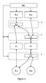
- FIG 3 shows an embodiment, in which the selection means SEL are used for controlling the second branching means Y and the switching means Z.
- the operating modes of the embodiment correspond to those shown in Figure 2 .
- the load M.1 is supplied by the frequency converter modules I.1 and I.2, which are controlled by the control means R.1.
- the frequency converter module I.1 is controlled by the control means R.1 and the frequency converter module I.2 by the control means R.2 in the second operating mode.
- the second branching means connected to the frequency converter module I.1 is simplified as a direct connection, and thus the frequency converter module I.1 is always controlled by the control means R.1.
- the second frequency converter module I.2, for its part, is controlled by either the control means R.1 (the first operating mode) or the control means R.2 (the second operating mode).
- the second branching means Y.2 is configured in such a manner that it can be used for selecting which one of the afore-mentioned control means controls the frequency converter module I.2.
- the selection means SEL are used for selecting the mode of the second branching means Y and that of the switching means. If necessary, it is also possible to control the control means directly by means of the selection means SEL by setting them active or inactive, for instance.
- the branching means in the first and second branching means may also comprise a plurality of electric devices, optical branching units and/or electric branching units connected to one another.
- the first and second branching means may also be integrated into a device implementing the functionality of both branching means.
- the arrangement according to the invention may also serve as a generator drive, in which case the load serves as a generator and power is directed from the load to the frequency converter. From the frequency converter, power may be supplied forward to a mains system, for example.
- FIG. 4 shows an embodiment of the invention for use in ships.
- the selection means may be used for selecting an operating mode in which six frequency converter modules I.1 to I.6 are connected in parallel for supplying a ship propeller drive M.1, or an operating mode in which each frequency converter module is connected to its own motor M.2 to M.7 rotating a belt conveyor drive used for unloading cargo.
- the selection means SEL for the control units is a switch, which may be used for selecting which control units are supplied with electric power and are thus active. Electric power is supplied to a control means R.1 or a group of controls means R.2 to R.6.
- Each frequency converter module I.1 to I.6 of the embodiment is connected via an optical fibre to the branching devices serving as second branching means Y.1 to Y.6.
- These branching devices may be implemented by a passive optical Y branching unit, where a light arriving at the input is distributed to the outputs.
- the branching devices may also be implemented by an electric device.
- the control means R.1 is connected via an optical fibre to a branching device serving as the first branching means X.1. It may be implemented by an afore-mentioned electric device, for instance.
- the control means R.1 controls the frequency converter modules I.1 to I.6 by means of connections established by the first branching means X.1 and the second branching means Y.1 to Y.6.
- the first branching means X.1 branches the connection from the control means R.1 to the second branching means Y.1 to Y.6.
- the second branching means Y.1 to Y.6 may also transmit information to the inactive control means R.2 to R.7. However, since they are inactive, they do not react to the information.
- the switching means Z are set to mode A, whereby the frequency converter modules I.1 to I.6 are connected in parallel to supply the ship propeller drive M.1.
- each control means R.2 to R.7 controls its own frequency converter module I.1 to I.6 in accordance with Figure 4 .
- the second branching means Y six point-to-point connections are established between the control means R.2 to R.7 and the frequency converter modules I.1 to I.6.
- the switching means Z are set to mode B, whereby each frequency converter module I.1 to I.6 is connected to its own motor M.2 to M.7.
- the same frequency converter modules I.1 to I.6 may be used for providing one high-power drive, or it may be used as a lower power drive (1/6 of the high-power drive) by controlling each module separately.
Landscapes
- Engineering & Computer Science (AREA)
- Power Engineering (AREA)
- Inverter Devices (AREA)
- Ac-Ac Conversion (AREA)
- Control Of Multiple Motors (AREA)
Abstract
Description
- The invention relates to frequency converters and particularly to arrangements in which a high-power frequency converter may be divided into a plurality of low-power frequency converters and, as a result, various loads may be connected to them.
- An electric drive typically comprises at least a power stage, a control means controlling the power stage, and a load, the operation of which is controlled by the power stage and the control means thereof. The power stage and its control are here referred to as a frequency converter. At its simplest, such an arrangement may be, for instance, a motor that is rotated by a frequency converter, which is controlled by a control card. If necessary, power stages may be connected in parallel to control the same load. The power stages may thus be controlled by the same control means.
- In certain processes, a high-power frequency converter comprising a plurality of power stages may be used for controlling one heavy load for some time, and when this heavy load is not needed, the same power stages may be utilised for providing a plurality of lower power frequency converters. It is thus not necessary to provide each load with its own frequency converter. This saves costs and space.
- However, it is difficult to manage such an arrangement by applying the prior art. Configuration of various combinations of control means and electric machines may be complicated and subject to errors.
- It is thus an object of the invention to develop a method and an apparatus implementing the method in such a manner that the above-mentioned problem is solved. The object of the invention is achieved by a method and a system, which are characterized by what is disclosed in the independent claims. The preferred embodiments of the invention are disclosed in the dependent claims.
- The invention is based on the idea that it is easy to replace control means controlling frequency converter modules by means of branching means. In this document, a frequency converter module refers to a module that comprises a power stage and may be controlled by said control means. The branching means combines the connections from the control means to the frequency converter modules into one connection. In addition, loads loading the frequency converters may be selected by switching means.
- An advantage of the method and system of the invention is user-friendliness, which can be achieved with low costs. Also, error susceptibility decreases with respect to the prior art.
- The invention will be described in greater detail in connection with the preferred embodiments and with reference to the accompanying drawings, in which:
-
Figure 1 shows a simplified block diagram of an arrangement of the invention for controlling frequency converter modules; -
Figure 2 shows an embodiment of the invention, in which some of first and second branching means are simplified as direct connections; -
Figure 3 shows an embodiment, in which a second branching means and switching means are controlled by selection means, and -
Figure 4 shows an embodiment of the invention for use in ships. -
Figure 1 shows a simplified block diagram of an arrangement of the invention for controlling frequency converter modules. The arrangement comprises at least two control means R.1 to R.m (m ≥ 2) for controlling the frequency converter modules. Of these control means, the active ones are selected by selection means SEL. The arrangement also comprises two or more frequency converter modules I.1 to I.n (n ≥ 2) and two or more loads M.1 to M.k (k ≥ 2). The frequency converter modules I.1 to I.n are connected to the loads by switching means Z, the number n of which corresponds to that of frequency converter modules. The connection means Z may be used for selecting the frequency converter module(s) supplying power to each load. In other words, the load to which the frequency converter module supplies power is selected by the switching means. Each switching means Z.1 to Z.n is arranged to establish a connection between one frequency converter module I.1 to I. n and one load M.1 to M.k at a time. An individual switching means Z.1 to Z.n may also refer to a direct connection between a frequency converter module and a load. - In addition, the arrangement of the invention comprises first branching means X and second branching means Y for establishing connections between the control means R.1 to R.m and the frequency converter modules I.1 to I.n. The first branching means X comprise m first branching means and the second branching means Y comprise n second branching means. The second branching means Y comprise at least one branching device, by which a connection may be established between a frequency converter module and two or more first branching means. Such a branching device may be, for instance, an optical passive branching unit or an electric device by which the functionality of an optical branching unit may be implemented between a frequency converter module and two or more first branching means X.1 to X.m. Connections may also be electric, in which case the branching device implements the functionality of an electric branching unit. In addition, combinations of optical and electric connections are possible. An example is a branching unit, by which an electric connection is branched to several optical connections. Similar branching devices may also be used in the first branching means X.
- Each control means R.1 to R.m is connected to a first branching means X.1 to X.m. Each first branching means X.1 to X.m serves to establish a connection between each control means R.1 to R.m and one or more second branching means Y.1 to Y.n. The first branching means X.1 to X.m may be adapted to convert a connection from an individual control means R.1 to R.m into several connections. Thus, it is possible to use one control means R.1 to R.m for controlling a plurality of frequency converter modules I.1 to I.n. In this document, a connection can refer to a uni- or bidirectional data transmission connection. The first branching means X.1 to X.m may be simplified as a direct connection, if there is only one connection to the second branching means Y. A direct connection can refer to, for example, an optical fibre or a pair of optical fibres from one of the control means R.1 to R.m to one of the second branching means Y directly. Instead of an optical connection, a direct connection may also be an electric connection, such as a connection realized by copper conductors.
- Like the first branching means X, the second branching means Y serve to establish a connection between each frequency converter module I.1 to I.n and one or more first branching means X. Each frequency converter module I.1 to I.n is connected to a second branching means Y.1 to Y.n. As in the above, the second branching means Y.1 to Y.n may be simplified as a direct connection, if there is only one connection to the first branching means X. However, the second branching means Y always comprise at least one branching device, by which a connection may be established between a frequency converter module and two or more first branching means.
-
Figure 2 shows an embodiment of the invention, in which the control means R.1 controls both frequency converter modules I.1 and I.2 in the first operating mode. The first branching means X.1 branches the connection to the branching means Y.1 and the branching means Y.2, from which there are connections to the frequency converter modules I.1 and I.2. Power is supplied to the load M.1 by both frequency converter modules I.1 and I.2, because in this operating mode a switching means Z.2 is in a state where there is a connection from the frequency converter module I.2 to the load M.1. No power is supplied to the load M.2. In the second operating mode, control means R.2 and R.3 are active. The control means R.2 controls the frequency converter module I.1 supplying power to the load M.1. The control means R.3 controls the frequency converter module I.2 supplying power to the load M.2, because the switching means Z.2 is in a state where there is a connection from the frequency converter module I.2 to the load M.2. The first branching means X.1 is a branching device, and the second and third of the first branching means X are simplified as direct connections in this embodiment. The active control means are selected by a selection means SEL. - The switching means Z for loads may be in connection with the selection means SEL for control means and act responsive to the selection means. In this case, simultaneously with selecting the operating mode for the control means, the operating mode for the switching means may also be selected. It is thus possible to choose the operating mode of the entire arrangement with one select operation.
- When the branching device is an electric device, it can be configured in such a manner that also the operating mode of that particular branching means may be selected. For instance, the second branching means Y may be adapted to operate responsive to the selection means SEL. When the branching means obtains the selection information, it may establish a point-to-point connection, for example. The branching means thus serves as a selector, by which, for instance in the case of the second branching means, the control means controlling the frequency converter module can be selected. When the branching means serve as a selector, the control means need not necessarily be activated separately.
-
Figure 3 shows an embodiment, in which the selection means SEL are used for controlling the second branching means Y and the switching means Z. The operating modes of the embodiment correspond to those shown inFigure 2 . In the first operating mode, the load M.1 is supplied by the frequency converter modules I.1 and I.2, which are controlled by the control means R.1. In this embodiment, unlike inFigure 2 , the frequency converter module I.1 is controlled by the control means R.1 and the frequency converter module I.2 by the control means R.2 in the second operating mode. The second branching means connected to the frequency converter module I.1 is simplified as a direct connection, and thus the frequency converter module I.1 is always controlled by the control means R.1. The second frequency converter module I.2, for its part, is controlled by either the control means R.1 (the first operating mode) or the control means R.2 (the second operating mode). The second branching means Y.2 is configured in such a manner that it can be used for selecting which one of the afore-mentioned control means controls the frequency converter module I.2. The selection means SEL are used for selecting the mode of the second branching means Y and that of the switching means. If necessary, it is also possible to control the control means directly by means of the selection means SEL by setting them active or inactive, for instance. - The branching means in the first and second branching means may also comprise a plurality of electric devices, optical branching units and/or electric branching units connected to one another. The first and second branching means may also be integrated into a device implementing the functionality of both branching means.
- The arrangement according to the invention may also serve as a generator drive, in which case the load serves as a generator and power is directed from the load to the frequency converter. From the frequency converter, power may be supplied forward to a mains system, for example.
-
Figure 4 shows an embodiment of the invention for use in ships. The selection means may be used for selecting an operating mode in which six frequency converter modules I.1 to I.6 are connected in parallel for supplying a ship propeller drive M.1, or an operating mode in which each frequency converter module is connected to its own motor M.2 to M.7 rotating a belt conveyor drive used for unloading cargo. The selection means SEL for the control units is a switch, which may be used for selecting which control units are supplied with electric power and are thus active. Electric power is supplied to a control means R.1 or a group of controls means R.2 to R.6. - Each frequency converter module I.1 to I.6 of the embodiment is connected via an optical fibre to the branching devices serving as second branching means Y.1 to Y.6. These branching devices may be implemented by a passive optical Y branching unit, where a light arriving at the input is distributed to the outputs. Alternatively, the branching devices may also be implemented by an electric device. The control means R.1 is connected via an optical fibre to a branching device serving as the first branching means X.1. It may be implemented by an afore-mentioned electric device, for instance.
- When the arrangement is used in an operating mode in which the control means R.1 is active, the control means R.1 controls the frequency converter modules I.1 to I.6 by means of connections established by the first branching means X.1 and the second branching means Y.1 to Y.6. The first branching means X.1 branches the connection from the control means R.1 to the second branching means Y.1 to Y.6. The second branching means Y.1 to Y.6 may also transmit information to the inactive control means R.2 to R.7. However, since they are inactive, they do not react to the information. In this operating mode, the switching means Z are set to mode A, whereby the frequency converter modules I.1 to I.6 are connected in parallel to supply the ship propeller drive M.1.
- When the arrangement of the embodiment is once again in the operating mode in which the control means R.2 to R.7 are active, each control means R.2 to R.7 controls its own frequency converter module I.1 to I.6 in accordance with
Figure 4 . By means of the second branching means Y, six point-to-point connections are established between the control means R.2 to R.7 and the frequency converter modules I.1 to I.6. In this operating mode, the switching means Z are set to mode B, whereby each frequency converter module I.1 to I.6 is connected to its own motor M.2 to M.7. Thus, the same frequency converter modules I.1 to I.6 may be used for providing one high-power drive, or it may be used as a lower power drive (1/6 of the high-power drive) by controlling each module separately. - It is obvious to a person skilled in the art that the basic idea of the invention may be implemented in many different ways. The invention and its embodiments are thus not restricted to the examples described above, but may vary within the scope of the claims.
Claims (14)
- An arrangement for controlling frequency converter modules of an electric drive, characterized in that the arrangement comprises
two or more control means (R.1 - R.m),
two or more frequency converter modules (I.1 to I.n),
two or more loads (M.1 to M.k), and switching means (Z) for connecting the frequency converter modules to the different loads of the arrangement,
selection means (SEL) for selecting active control means,
first branching means (X) and second branching means (Y), the first branching means (X) being arranged to establish connections between each control means (R.1 to R.m) and one or more second branching means (Y.1 to Y.n), and the second branching means (Y) being arranged to establish connections between each frequency converter module (I.1 to I.n) and one or more first branching means (X.1 to X.m) in such a manner that the second branching means (Y) comprise at least one branching device arranged to establish a connection between a frequency converter module (I.1 to I.n) and two or more first branching means (X.1 to X.m). - An arrangement as claimed in claim 1, characterized in that the frequency converter modules are arranged to control alternatively a first motor (M.1) or several motors (M.2 to M.k) having less power than the first motor (M.1).
- An arrangement as claimed in claim 1 or 2, characterized in that the arrangement is an electric drive for use in ships.
- An arrangement as claimed in any one of claims 1 to 3, characterized in that connections between the control means (R.1 to R.m) and the first branching means (X), connections between the first branching means (X) and the second branching means (Y) and connections between the second branching means (Y) and the frequency converter modules (I.1 to I.n) are implemented by an optical fibre.
- An arrangement as claimed in any one of claims 1 to 4, characterized in that the branching means comprise one or more branching devices, the branching device comprising two passive optical Y branching units.
- An arrangement as claimed in any one of claims 1 to 5, characterized in that the branching means comprise one or more electric devices, the device being arranged to implement the functionality of one or more branching devices, the branching device comprising means for implementing the functionality of two optical Y branching units.
- An arrangement as claimed in any one of claims 1 to 6, characterized in that the means (SEL) for selecting active control means is a selector, which may be used for selecting the control means (R.1 to R.m) to which electric power is supplied.
- An arrangement as claimed in any one of claims 1 to 7, characterized in that the first branching means (X) comprise one or more electric devices, by which a connection between a control unit and two or more second branching means may be established.
- An arrangement as claimed in any one of claims 1 to 8, characterized in that each switching means (Z.1 to Z.n) is arranged to establish one connection between one frequency converter module (I.1 to I.n) and one load (M.1 to M.k) at a time.
- An arrangement as claimed in any one of claims 1 to 9, characterized in that the switching means (Z) are arranged to operate responsive to the selection means (SEL).
- An arrangement as claimed in any one of claims 1 to 10, characterized in that the second branching means (Y) are arranged to operate responsive to the selection means (SEL).
- An arrangement as claimed in any one of claims 1 to 11, characterized in that the first branching means (X) and the second branching means (Y) are integrated into a device that is arranged to implement the functionality of both branching means.
- An arrangement as claimed in any one of claims 1 to 12, characterized in that the arrangement comprises, selectable by the selection means,
a first operating mode, in which the frequency converter modules are connected to supply a ship propeller drive, and
a second operating mode, in which each frequency converter module is connected to its own motor, the motors being arranged to rotate a belt conveyor drive used for unloading cargo. - A method for controlling frequency converter modules in connection with an electric drive arrangement, the arrangement comprising two or more control means, two or more frequency converter modules, two or more loads, and one or more switching means for connecting the frequency converter modules to the different loads of the arrangement, characterized in that the method comprises the steps of
selecting active control means, by which the frequency converter modules are controlled,
selecting loads loading the frequency converter modules by means of the switching means,
establishing a connection between each control means and one or more frequency converter modules for controlling the frequency converter modules by branching the connection from each control means to one or more connections and combining one or more afore-mentioned branched connection into one connection to the frequency converter module, and
controlling the frequency converter modules loaded by the loads by means of the control means.
Applications Claiming Priority (1)
| Application Number | Priority Date | Filing Date | Title |
|---|---|---|---|
| FI20105395A FI122161B (en) | 2010-04-15 | 2010-04-15 | Arrangement and procedure for controlling frequency modules |
Publications (2)
| Publication Number | Publication Date |
|---|---|
| EP2378653A2 true EP2378653A2 (en) | 2011-10-19 |
| EP2378653A3 EP2378653A3 (en) | 2017-06-07 |
Family
ID=42133239
Family Applications (1)
| Application Number | Title | Priority Date | Filing Date |
|---|---|---|---|
| EP11160603.4A Withdrawn EP2378653A3 (en) | 2010-04-15 | 2011-03-31 | Arrangement and method for controlling frequency converter modules |
Country Status (4)
| Country | Link |
|---|---|
| US (1) | US8581528B2 (en) |
| EP (1) | EP2378653A3 (en) |
| CN (1) | CN102223117B (en) |
| FI (1) | FI122161B (en) |
Families Citing this family (4)
| Publication number | Priority date | Publication date | Assignee | Title |
|---|---|---|---|---|
| US8228009B2 (en) * | 2009-07-27 | 2012-07-24 | Parker-Hannifin Corporation | Twin motor actuator |
| US9325273B2 (en) | 2013-09-30 | 2016-04-26 | General Electric Company | Method and system for driving electric machines |
| CN105305890B (en) * | 2015-09-30 | 2019-02-12 | 武汉船用机械有限责任公司 | A motor control system |
| CN111585497A (en) * | 2020-05-25 | 2020-08-25 | 中国舰船研究设计中心 | Electric transmission system based on time-sharing multiplexing of frequency converter |
Family Cites Families (19)
| Publication number | Priority date | Publication date | Assignee | Title |
|---|---|---|---|---|
| US4661714A (en) * | 1985-06-17 | 1987-04-28 | Satterthwaite J Glenn | Electric marine propulsion system |
| JPH06121473A (en) | 1992-10-06 | 1994-04-28 | Mitsubishi Electric Corp | Variable voltage variable frequency converter switching device |
| US6037752A (en) * | 1997-06-30 | 2000-03-14 | Hamilton Sundstrand Corporation | Fault tolerant starting/generating system |
| DE19739917A1 (en) | 1997-09-11 | 1999-03-18 | Siemens Ag | System for supplying electromotive consumers with electrical energy |
| DE19821251A1 (en) | 1998-05-12 | 1999-11-18 | Csm Gmbh | Drive system for a spinning machine with a number of spindle drive motors |
| ATE365391T1 (en) | 2001-01-22 | 2007-07-15 | Siemens Ag | ENERGY SYSTEM FOR WATERCRAFT |
| CN2478281Y (en) | 2001-04-25 | 2002-02-20 | 张金榜 | Switching device for multiple frequency transformer and motor |
| DE10215822B4 (en) | 2002-04-10 | 2013-03-07 | Sew-Eurodrive Gmbh & Co. Kg | Inverter system and procedure |
| JP2004192693A (en) | 2002-12-10 | 2004-07-08 | Matsushita Electric Ind Co Ltd | Motor control device |
| JP4140552B2 (en) * | 2004-04-28 | 2008-08-27 | トヨタ自動車株式会社 | Automotive power supply device and automobile equipped with the same |
| US7439634B2 (en) * | 2004-08-24 | 2008-10-21 | Honeywell International Inc. | Electrical starting, generation, conversion and distribution system architecture for a more electric vehicle |
| US20060071559A1 (en) * | 2004-09-30 | 2006-04-06 | Michael Hanson | Individually and redundantly addressable solid-state power controllers on multiple modules in a power distribution assembly |
| DE102005025573A1 (en) * | 2005-06-03 | 2006-12-07 | Ellenberger & Poensgen Gmbh | Multiplexing system for boats or caravans |
| RU2383451C1 (en) * | 2006-01-17 | 2010-03-10 | Абб Швайц Аг | Drive fuel-electric system |
| FR2899734B1 (en) * | 2006-04-05 | 2016-04-15 | Thales Sa | DEVICE FOR SUPPLYING A PLURALITY OF LOADS FROM AN ELECTRIC POWER SUPPLY NETWORK |
| FR2907760B1 (en) * | 2006-10-25 | 2009-06-12 | Airbus France Sas | SYSTEM AND METHOD FOR POWER SUPPLY ON BOARD AN AIRCRAFT. |
| CN1949660A (en) | 2006-11-09 | 2007-04-18 | 智勇 | Intelligent controller for seamless embedded frequency change speed regulating system |
| US7952306B2 (en) * | 2007-06-01 | 2011-05-31 | Progress Rail Services Corp | Power system with multiple generator units |
| CN201260148Y (en) | 2008-08-19 | 2009-06-17 | 钟祥市金汉江纤维素有限公司 | Apparatus for remote controlling multiple different devices by one frequency transformer |
-
2010
- 2010-04-15 FI FI20105395A patent/FI122161B/en active IP Right Grant
-
2011
- 2011-03-31 EP EP11160603.4A patent/EP2378653A3/en not_active Withdrawn
- 2011-04-12 US US13/084,858 patent/US8581528B2/en active Active
- 2011-04-14 CN CN201110096349.6A patent/CN102223117B/en active Active
Non-Patent Citations (1)
| Title |
|---|
| None |
Also Published As
| Publication number | Publication date |
|---|---|
| US20110254473A1 (en) | 2011-10-20 |
| FI20105395A0 (en) | 2010-04-15 |
| CN102223117B (en) | 2014-06-04 |
| FI122161B (en) | 2011-09-15 |
| EP2378653A3 (en) | 2017-06-07 |
| CN102223117A (en) | 2011-10-19 |
| US8581528B2 (en) | 2013-11-12 |
Similar Documents
| Publication | Publication Date | Title |
|---|---|---|
| EP2378653A2 (en) | Arrangement and method for controlling frequency converter modules | |
| US20110260652A1 (en) | Wireless light control system with control apparatus and method thereof | |
| JP6156754B2 (en) | Power management for electronic devices | |
| CN102439944B (en) | Architecture with optimized interface for aircraft hybrid cabin control panel system | |
| RU2007116767A (en) | POWER SUPPLY SYSTEM AND CONTROL OF ELECTRICAL EQUIPMENT OF THE ENGINE OF THE AIRCRAFT ENGINE AND ITS EQUIPMENT | |
| CN110275805B (en) | Full-automatic test system for MCU chip | |
| CN101902661A (en) | Power supply system, communication device and power supply control method | |
| US20170093310A1 (en) | Bluetooth motor controller, brushless direct current motor, and multi-motor system comprising the same | |
| CN113141132A (en) | Control method, system and equipment for driving multiple motors to operate | |
| US11031633B2 (en) | Ship or power plant voltage supply system | |
| CN103685594B (en) | Electronic equipment and addressing method | |
| AU2021287623A1 (en) | Method and arrangements in an electric mining machine | |
| CN105549472B (en) | A kind of anchoring system and its control method | |
| EP3323280A1 (en) | A method of operating an agricultural system having a tractor and an implement, an agricultural system, and a computer program product | |
| CN1881141B (en) | Apparatus and method for performing multiple functions using a unique port in a wireless terminal | |
| KR101587468B1 (en) | Speed control apparatus and method of multi motor | |
| CN106557141A (en) | A kind of electronic equipment | |
| JP2011176904A (en) | Distributed power supply system, control method, program, and recording medium | |
| US8515583B2 (en) | Machine motion control system for testing electronic components | |
| EP4518142A1 (en) | Electrical system for cable transportation plant or power generation plant | |
| US20230136636A1 (en) | Solenoid valve control device | |
| CN201842093U (en) | Traction system and control device for traction system | |
| CN109888496B (en) | Phased array antenna beam control device and system | |
| EP1837131A1 (en) | Manipulator, for example an industrial robot, and drive device for a manipulator | |
| JP2003348887A (en) | Test system for motor driver |
Legal Events
| Date | Code | Title | Description |
|---|---|---|---|
| AK | Designated contracting states |
Kind code of ref document: A2 Designated state(s): AL AT BE BG CH CY CZ DE DK EE ES FI FR GB GR HR HU IE IS IT LI LT LU LV MC MK MT NL NO PL PT RO RS SE SI SK SM TR |
|
| AX | Request for extension of the european patent |
Extension state: BA ME |
|
| PUAI | Public reference made under article 153(3) epc to a published international application that has entered the european phase |
Free format text: ORIGINAL CODE: 0009012 |
|
| PUAL | Search report despatched |
Free format text: ORIGINAL CODE: 0009013 |
|
| AK | Designated contracting states |
Kind code of ref document: A3 Designated state(s): AL AT BE BG CH CY CZ DE DK EE ES FI FR GB GR HR HU IE IS IT LI LT LU LV MC MK MT NL NO PL PT RO RS SE SI SK SM TR |
|
| AX | Request for extension of the european patent |
Extension state: BA ME |
|
| RIC1 | Information provided on ipc code assigned before grant |
Ipc: H02J 3/00 20060101ALI20170428BHEP Ipc: H02M 5/458 20060101AFI20170428BHEP |
|
| PUAL | Search report despatched |
Free format text: ORIGINAL CODE: 0009013 |
|
| STAA | Information on the status of an ep patent application or granted ep patent |
Free format text: STATUS: REQUEST FOR EXAMINATION WAS MADE |
|
| STAA | Information on the status of an ep patent application or granted ep patent |
Free format text: STATUS: THE APPLICATION HAS BEEN WITHDRAWN |
|
| 17P | Request for examination filed |
Effective date: 20170713 |
|
| RBV | Designated contracting states (corrected) |
Designated state(s): AL AT BE BG CH CY CZ DE DK EE ES FI FR GB GR HR HU IE IS IT LI LT LU LV MC MK MT NL NO PL PT RO RS SE SI SK SM TR |
|
| 18W | Application withdrawn |
Effective date: 20170814 |