EP2378321A1 - Holey fiber - Google Patents
Holey fiber Download PDFInfo
- Publication number
- EP2378321A1 EP2378321A1 EP09801905A EP09801905A EP2378321A1 EP 2378321 A1 EP2378321 A1 EP 2378321A1 EP 09801905 A EP09801905 A EP 09801905A EP 09801905 A EP09801905 A EP 09801905A EP 2378321 A1 EP2378321 A1 EP 2378321A1
- Authority
- EP
- European Patent Office
- Prior art keywords
- holes
- mode
- holey fiber
- equal
- micrometers
- Prior art date
- Legal status (The legal status is an assumption and is not a legal conclusion. Google has not performed a legal analysis and makes no representation as to the accuracy of the status listed.)
- Withdrawn
Links
- 239000000835 fiber Substances 0.000 title claims abstract description 65
- 238000005253 cladding Methods 0.000 claims abstract description 10
- 238000005452 bending Methods 0.000 claims description 32
- 230000001902 propagating effect Effects 0.000 abstract description 3
- 238000004364 calculation method Methods 0.000 description 26
- 238000009826 distribution Methods 0.000 description 9
- 239000011521 glass Substances 0.000 description 8
- 230000000644 propagated effect Effects 0.000 description 8
- 238000000034 method Methods 0.000 description 7
- 239000013307 optical fiber Substances 0.000 description 6
- 230000003287 optical effect Effects 0.000 description 4
- 230000002238 attenuated effect Effects 0.000 description 2
- 230000000694 effects Effects 0.000 description 2
- 238000012681 fiber drawing Methods 0.000 description 2
- 230000012447 hatching Effects 0.000 description 2
- 238000003754 machining Methods 0.000 description 2
- 239000007787 solid Substances 0.000 description 2
- VYPSYNLAJGMNEJ-UHFFFAOYSA-N Silicium dioxide Chemical compound O=[Si]=O VYPSYNLAJGMNEJ-UHFFFAOYSA-N 0.000 description 1
- 230000005540 biological transmission Effects 0.000 description 1
- 230000008878 coupling Effects 0.000 description 1
- 238000010168 coupling process Methods 0.000 description 1
- 238000005859 coupling reaction Methods 0.000 description 1
- 239000002019 doping agent Substances 0.000 description 1
- 238000004519 manufacturing process Methods 0.000 description 1
- 235000012239 silicon dioxide Nutrition 0.000 description 1
- 238000004088 simulation Methods 0.000 description 1
Images





Classifications
-
- G—PHYSICS
- G02—OPTICS
- G02B—OPTICAL ELEMENTS, SYSTEMS OR APPARATUS
- G02B6/00—Light guides; Structural details of arrangements comprising light guides and other optical elements, e.g. couplings
- G02B6/02—Optical fibres with cladding with or without a coating
- G02B6/02295—Microstructured optical fibre
- G02B6/02314—Plurality of longitudinal structures extending along optical fibre axis, e.g. holes
- G02B6/02342—Plurality of longitudinal structures extending along optical fibre axis, e.g. holes characterised by cladding features, i.e. light confining region
- G02B6/02366—Single ring of structures, e.g. "air clad"
-
- G—PHYSICS
- G02—OPTICS
- G02B—OPTICAL ELEMENTS, SYSTEMS OR APPARATUS
- G02B6/00—Light guides; Structural details of arrangements comprising light guides and other optical elements, e.g. couplings
- G02B6/02—Optical fibres with cladding with or without a coating
- G02B6/02004—Optical fibres with cladding with or without a coating characterised by the core effective area or mode field radius
- G02B6/02009—Large effective area or mode field radius, e.g. to reduce nonlinear effects in single mode fibres
Definitions
- the present invention relates to a holey fiber.
- a holey fiber is a new type of optical fiber that includes a core portion positioned at a core thereof, and a cladding portion having a plurality of holes arranged around the core portion.
- this optical fiber an average refractive index of the cladding portion is reduced by the holes, and the core portion is caused to propagate light using the principle of total reflection of light.
- this holey fiber because it is possible to reduce optical nonlinearity by increasing an effective core area, application of the optical fiber as a low-nonlinear transmission medium to optical communications or to power delivery to transmit high power light for laser machining and the like is expected.
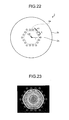
- FIG. 22 is a schematic cross-sectional view of the holey fiber described in Non-patent Literature 1.
- a holey fiber 2 includes a core portion 2a, and a cladding portion 2b positioned around the core portion 2a and having 18 holes 2c formed around the core portion 2a.
- the holes 2c each have a hole diameter of d1, and are arranged on lattice points forming a hexagon selected from lattice points of a triangular lattice. According to Non-patent Literature 1, in the holey fiber 2 depicted in FIG.
- the effective core area becomes very large at 1400 ⁇ m 2 when a wavelength is 1064 nanometers
- a confinement loss of the LP01 mode that is a fundamental mode of a propagation mode becomes small at equal to or smaller than 0.3 dB/m
- a confinement loss of the LP11 mode that is a higher-order mode of second order becomes large at 1 dB/m
- the holey fiber 2 is considered to be capable of achieving a substantial single-mode operation.
- Non-patent Literature 1 it is assumed that the holey fiber 2 of a length of 1 meter to 2 meters is used. Therefore, the holey fiber 2 is considered to perform the substantial single-mode operation as long as a difference between the confinement loss of the LP11 mode and the confinement loss of the LP01 mode for a total length is equal to or larger than 0.7 dB. Furthermore, a bending loss upon bending the holey fiber 2 with a radius of 100 millimeters is described to be about 4.4 to 4.5 dB/m. A distance r1 from a center 01 of the hexagon formed by the holes 2c to an apex is 36 micrometers when A is 12.0 micrometers as described above.
- Non-patent Literature 1 Y. Tsuchida, et al., "Design of Single-Mode Leakage Channel Fibers with Large-Mode-Area and Low Bending Loss", OECC 2008, P-9
- laser light beams used in laser machining are preferably isotropically circular. Therefore, it is preferable for a holey fiber to have a field distribution of propagated light that is circular. Further, it is also preferable for a holey fiber practically used in optical communications to have a field distribution of propagated light that is circular to reduce a connection loss with another optical fiber.
- FIG. 23 depicts a field distribution of light having a wavelength of 1064 nanometers propagated through the holey fiber 2 depicted in FIG. 22 .
- intensity of a field at a center portion is 1.0, and from the center, each range having the intensity attenuated by 10% is illustrated with a different hatching.
- the holey fiber 2 has a field distribution of light that is hexagonal, and thus has propagated light of a shape that is far from a preferable shape.
- the present invention has been made in view of the above, and an object of the invention is to provide a holey fiber capable of propagating light in a form preferable for practical uses while achieving a substantial single-mode operation and low nonlinearity.
- a holey fiber includes: a core portion; and a cladding portion positioned around a periphery of the core portion and having holes arranged circularly around the core portion.
- 12 to 36 of the holes are arranged circularly at a radius of 36 to 48 micrometers around an approximate center of the core portion, a hole diameter is in a range of 2.0 to 11.0 micrometers, and at a wavelength of 1064 nanometers, a single-mode operation is substantially performed and an effective core area is equal to or greater than 1500 ⁇ m 2 .
- the holey fiber according to the invention further has a length for which a difference between a confinement loss of a fundamental mode and a confinement loss of a higher-order mode of second order in a total length is equal to or greater than 0.7 dB at the wavelength of 1064 nanometers.
- a bending loss upon bending with a radius of 100 millimeters at the wavelength of 1064 nanometers is equal to or smaller than 10 dB/m.
- the present invention achieves an effect that it is possible to realize a holey fiber capable of propagating light in a form preferable for practical uses while achieving a substantial single-mode operation and low nonlinearity.
- FIG. 1 is a schematic cross-sectional view of a holey fiber 1 according to an embodiment of the present invention.
- the holey fiber 1 includes a core portion 1a, and a cladding portion 1b positioned around a periphery of the core portion 1a.
- the core portion 1a and the cladding portion 1b are made of pure silica glass not added with a dopant for adjusting a refractive index.
- the cladding portion 1b includes holes 1c arranged around the core portion 1a.
- the number of the holes 1c is 18, and the holes 1c are arranged circularly around a center 0 of the core portion 1a.
- a radius r of a circle formed by the holes 1c (hereinafter, "hole arrangement radius") is 36 micrometers. When a hole diameter (diameter) d of the holes 1c is 5.5 micrometers.
- FIG. 2 depicts a field distribution of light having a wavelength of 1064 nanometers propagated through the holey fiber 1 depicted in FIG. 1 .
- intensity of a field at a center portion is 1.0, and a different hatching is used to show, from the center, each range in which the intensity is attenuated by 10%.
- the holey fiber 1 has the field distribution of light that is circular, which is of a shape preferable for practical uses.
- the number of holes, the hole arrangement radius, and the hole diameter of the holey fiber 1 are set as described above, when the wavelength is 1064 nanometers, an effective core area of the LP01 mode that is a fundamental mode becomes very large at 1812 ⁇ m 2 which is equal to or larger than 1500 ⁇ m 2 , the confinement loss of the LP01 mode becomes small at 0.25 dB/m, which is equal to or smaller than 0.3 dB/m, and the confinement loss of the LP11 mode becomes large at 1.28 dB/m, which is equal to larger than 1 dB/m. Consequently, when a length equal to or larger than 1 meter is used, it is possible to achieve a substantial single-mode operation.
- the bending loss when the holey fiber 1 is bent with a diameter of 100 millimeters as is done when the holey fiber is wound around a bobbin or the like, the bending loss is about 4.4 dB/m, which is equal to or smaller than 10 dB/m, which is preferable for practical uses.
- the bending loss refers to a bending loss upon bending with a radius of 100 millimeters.
- the numbers of holes are the same, values of the hole arrangement radius r of the holey fiber 1 and the distance r1 of the holey fiber 2 are the same, and also values of the bending loss are substantially the same.
- the holey fiber 1 has a larger effective core area of 1812 ⁇ m 2 .
- a holey fiber with holes circularly arranged similarly to those of the holey fiber 1 depicted in FIG. 1 if the number of holes n is 12 to 36, the hole arrangement radius r is 36 to 48 micrometers, and the hole radius d is in a range of 2.0 to 11.0 micrometers, it is possible to realize a holey fiber substantially achieving the single-mode operation at the wavelength of 1064 nanometers and having the effective core area equal to or larger than 1500 ⁇ m 2 .
- FEM finite element method
- a calculation result is explained for a holey fiber having holes circularly arranged similarly to those of the holey fiber 1 depicted in FIG. 1 when the number of holes n is set to be 12, 18, 24, and 36 and the hole arrangement radius r is set to be 36 micrometers, 39 micrometers, 42 micrometers, and 45 micrometers.
- the wavelength used in each calculation is 1064 nanometers.
- FIG. 3 depicts a relationship between the hole diameter d and the confinement loss of the fundamental mode when the number of holes n is 12.
- a line L1 indicates where the confinement loss is 0.3 dB/m.
- d for each r, there is a range of d for which the confinement loss of the fundamental mode becomes equal to or smaller than 0.3 dB/m.
- FIG. 4 depicts a relationship between the hole diameter d and the confinement loss of the higher-order mode of second order when the number of holes n is 12.
- d the confinement loss of the higher-order mode of second order becomes equal to or larger than 1.0 dB/m.
- a confinement loss of a higher-order mode higher than the higher-order mode of second order is also equal to or larger than 1.0 dB/m. Therefore, only the higher-order mode of second order is considered below as the higher-order mode.
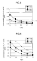
- FIG. 5 depicts a relationship between the hole diameter d and the confinement loss of the fundamental mode when the number of holes n is 18.
- a line L2 indicates where the confinement loss is 0.3 dB/m.
- d the confinement loss of the fundamental mode becomes equal to or smaller than 0.3 dB/m.
- FIG. 6 depicts a relationship between the hole diameter d and the confinement loss of the higher-order mode when the number of holes n is 18. As depicted in FIG. 6 , for each r, there is a range of d for which the confinement loss of the higher-order mode becomes equal to or larger than 1.0 dB/m.
- FIG. 7 depicts a relationship between the hole diameter d and the confinement loss of the fundamental mode when the number of holes n is 24.
- a line L3 indicates where the confinement loss is 0.3 dB/m.
- d the confinement loss of the fundamental mode becomes equal to or smaller than 0.3 dB/m.
- FIG. 8 depicts a relationship between the hole diameter d and the confinement loss of the higher-order mode when the number of holes n is 24. As depicted in FIG. 8 , for each r, there is a range of d for which the confinement loss of the higher-order mode becomes equal to or larger than 1.0 dB/m.
- FIG. 9 depicts a relationship between the hole diameter d and the confinement loss of the fundamental mode when the number of holes n is 36.
- a line L4 indicates where the confinement loss is 0.3 dB/m.
- d the confinement loss of the fundamental mode becomes equal to or smaller than 0.3 dB/m.
- FIG. 10 depicts a relationship between the hole diameter d and the confinement loss of the higher-order mode when the number of holes n is 36. As depicted in FIG. 10 , for each r, there is a range of d for which the confinement loss of the higher-order mode becomes equal to or larger than 1.0 dB/m.
- FIG. 11 depicts values of the hole diameter d at which the confinement loss of the fundamental mode is equal to or smaller than 0.3 dB/m, the confinement loss of the higher-order mode is equal to or larger than 1.0 dB/m, and the substantial single-mode operation is achieved, with respect to combinations of the hole arrangement radius r and the number of holes n.
- d there are values of d at which the substantial single-mode operation is achieved for each combination of the hole arrangement radius r and the number of holes n.
- d at which the substantial single-mode operation is achieved is in a range of 9.5 to 11.0 micrometers when the number of holes n is 12, in a range of 5.5 to 6.5 micrometers when the number of holes n is 18, in a range of 3.9 to 4.5 micrometers when the number of holes n is 24, and in a range of 2.2 to 2.4 micrometers when the number of holes n is 36.
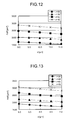
- FIG. 12 depicts a relationship between the hole diameter d and an effective core area Aeff when the number of holes n is 12.
- the effective core area Aeff is equal to or larger than 1500 ⁇ m 2 at d of 11.0 micrometers or smaller, for all of the values of the hole arrangement radius r.
- FIG. 13 depicts a relationship between the hole diameter d and the effective core area Aeff when the number of holes n is 18.
- the effective core area Aeff is equal to or larger than 1500 ⁇ m 2 at d of 7.0 micrometers or smaller, for all of the values of the hole arrangement radius r.
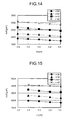
- FIG. 14 depicts a relationship between the hole diameter d and the effective core area Aeff when the number of holes n is 24.
- the effective core area Aeff is equal to or larger than 1500 ⁇ m 2 at d of 5.5 micrometers or smaller, for all of the values of the hole arrangement radius r.
- FIG. 15 depicts a relationship between the hole diameter d and the effective core area Aeff when the number of holes n is 36.
- the effective core area Aeff is equal to or larger than 1500 ⁇ m 2 at d in a range of 2.0 to 3.5 micrometers, for all of the values of the hole arrangement radius r.
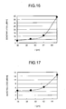
- FIG. 16 depicts a relationship between the hole arrangement radius r and the bending loss when the number of holes n is 12.
- the hole diameter d is set to be the values depicted in FIG. 11 according to each value of the hole arrangement radius r. For example, d is 9.5 ⁇ m when r is 36 ⁇ m.
- the bending loss of the holey fiber increases as the hole arrangement radius r is increased. Therefore, by setting the hole arrangement radius r to be equal to or smaller than a predetermined value as appropriate, it is possible to achieve a desired bending loss. For example, when r is 36 micrometers or 39 micrometers, the bending loss becomes 3.13 dB/m or 5.66 dB/m respectively, which is equal to or smaller than 10 dB/m.
- FIG. 17 depicts a relationship between the hole arrangement radius r and the bending loss when the number of holes n is 18.
- the hole diameter d is set to be the values depicted in FIG. 11 according to each value of the hole arrangement radius r.
- the bending loss becomes equal to or smaller than 6.17 dB/m.
- FIG. 18 depicts a relationship between the hole arrangement radius r and the bending loss when the number of holes n is 24.
- the hole diameter d is set to be the values depicted in FIG. 11 according to each value of the hole arrangement radius r.
- the bending loss becomes equal to or smaller than 6.82 dB/m.
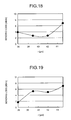
- FIG. 19 depicts a relationship between the hole arrangement radius r and the bending loss when the number of holes n is 36.
- the hole diameter d is set to be the values depicted in FIG. 11 according to each value of the hole arrangement radius r.
- the bending loss becomes equal to or smaller than 7.03 dB/m.
- FIG. 20 depicts calculation examples 1 to 14 of some of the results depicted in FIGS. 3 to 19 and of an example with the hole arrangement radius r of 48 micrometers.
- "n" represents the number of holes
- "d” represents a hole diameter
- "r” represents a hole arrangement radius
- "Aeff” represents an effective core area.
- the confinement loss is equal to or smaller than 0.3 dB/m in the LP01 mode, and is equal to or larger than 1.0 dB/m in the LP11 mode, the single-mode operation is substantially achieved, and the effective core area is equal to or larger than 1500 ⁇ m 2 .
- the bending loss is equal to or smaller than 10 dB/m.
- the confinement loss of the LP01 mode equal to or smaller than 0.3 dB/m and the confinement loss of the LP11 mode equal to larger than 1.0 dB/m are considered to be conditions of the substantial single-mode operation, and combinations of the number of holes n, the hole diameter d, and the hole arrangement radius r satisfying these conditions are depicted.
- these conditions of the confinement loss are assumed for a case of using the holey fiber of about 1 meter in length, and the holey fiber according to the present invention is not limited thereto. For example, as depicted in FIGS.
- the holey fiber has a length for which a difference between the confinement loss of the LP01 mode and the confinement loss of the LP11 mode in a total length is equal to or larger than 0.7 dB, it is possible to achieve the substantial single-mode operation. Therefore, such a holey fiber is included in the present invention.
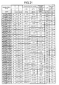
- FIG. 21 depicts calculation examples 15 to 44 of a confinement loss, a bending loss, and a shortest length for combinations of the number of holes n, the hole diameter d, and the hole arrangement radius r.
- the structure of the holey fiber is similar to that of the holey fiber 1 depicted in FIG. 1 .
- the shortest length refers to the shortest length at which the difference between the confinement loss of the LP01 mode and the confinement loss of the LP11 mode in a total length becomes 0.7 dB or greater, i.e., a length at which the difference becomes 0.7 dB.
- This shortest length is expressed as 0.7/(B-A) [m], where A [dB/m] represents a value of the confinement loss of the LP01 mode, and B [dB/m] represents a value of the confinement loss of the LP11 mode.
- the shortest length is 0.6 meter. That is, for the combination of the number of holes n of 24, the hole diameter d of 4.5 micrometers, and the hole arrangement radius r of 48 micrometers as in the calculation example 15, the substantial single-mode operation is achieved even if the length is very short at 0.6 meter.
- the shortest length is 260.6 meters. That is, for the combination of the number of holes n of 24, the hole diameter d of 7.5 micrometers, and the hole arrangement radius r of 48 micrometers as in the calculation example 18, the substantial single-mode operation is achieved when the length is made equal to or larger than 260.6 meters.
- the shortest length is 0.5 meter. That is, for the combination of the number of holes n of 24, the hole diameter d of 4.5 micrometers, and the hole arrangement radius r of 45 micrometers as in the calculation example 19, a substantial single-mode operation is achieved even when the length is very short at 0.5 meter.
- the shortest length is 210.6 meters. That is, in the combination of the number of holes n of 24, the hole diameter d of 7.5 micrometers, and the hole arrangement radius r of 45 micrometers as in the calculation example 22, a substantial single-mode operation is achieved when the length is made equal to or larger than 210.6 meters.
- the hole diameter d is set larger.
- the hole diameter d is set larger than that in the calculation example 19.
- the bending loss is 7.96 ⁇ 10 -2 dB/m in the calculation example 18 and is 2.14 ⁇ 10 -2 dB/m in the calculation example 22, which are equal to or smaller than 0.1 dB/m.
- the effective core area of the LP01 mode is equal to larger than 1500 ⁇ m 2
- FIG. 21 a shortest length of the holey fiber for which the difference between the confinement loss of the LP01 mode and the confinement loss of the LP11 mode becomes equal to or larger than 0.7 dB in the total length is illustrated. It is possible to achieve the single mode operation more infallibly and thus it is even more preferable if the holey fiber has a length for which the difference between the confinement losses becomes equal to or larger than 3.0 dB.
- the holey fiber according to the present invention may be manufactured by the following method. For example, a stack-and-draw method of arranging a solid glass rod to be a core portion near a center axis of a hollow glass tube, arranging hollow glass capillaries to form holes around the glass rod, forming an optical-fiber preform by further filling a solid glass rod around them, and fiber drawing the preform.
- the glass capillaries for forming the holes around the glass rod to be the core portion are naturally arranged along a clean circle, and thus it is possible to manufacture the holey fiber easily.
- a method of perforating holes in a circular arrangement through a glass rod optical-fiber preform, and fiber drawing may be used.
- the holey fiber according to the present invention is useful for optical communications or power delivery or the like, and is particularly suitable for transmitting high-power light.
Landscapes
- Physics & Mathematics (AREA)
- General Physics & Mathematics (AREA)
- Optics & Photonics (AREA)
- Optical Fibers, Optical Fiber Cores, And Optical Fiber Bundles (AREA)
Abstract
Description
- The present invention relates to a holey fiber.
- A holey fiber is a new type of optical fiber that includes a core portion positioned at a core thereof, and a cladding portion having a plurality of holes arranged around the core portion. In this optical fiber, an average refractive index of the cladding portion is reduced by the holes, and the core portion is caused to propagate light using the principle of total reflection of light. In this holey fiber, because it is possible to reduce optical nonlinearity by increasing an effective core area, application of the optical fiber as a low-nonlinear transmission medium to optical communications or to power delivery to transmit high power light for laser machining and the like is expected.
- To further increase an effective core area of a holey fiber, a holey fiber with a structure formed with holes forming only one layer around a core portion has been disclosed (Non-patent Literature 1).
FIG. 22 is a schematic cross-sectional view of the holey fiber described inNon-patent Literature 1. Aholey fiber 2 includes acore portion 2a, and acladding portion 2b positioned around thecore portion 2a and having 18holes 2c formed around thecore portion 2a. Theholes 2c each have a hole diameter of d1, and are arranged on lattice points forming a hexagon selected from lattice points of a triangular lattice. According toNon-patent Literature 1, in theholey fiber 2 depicted inFIG. 22 , when A, which is a lattice constant, i.e., an interval between theholes 2c, is 12.0 micrometers (µm) and d1/Λ is 0.48 (i.e., d1 is 5.76 micrometers), the effective core area becomes very large at 1400 µm2 when a wavelength is 1064 nanometers, a confinement loss of the LP01 mode that is a fundamental mode of a propagation mode becomes small at equal to or smaller than 0.3 dB/m, a confinement loss of the LP11 mode that is a higher-order mode of second order becomes large at 1 dB/m, and thus theholey fiber 2 is considered to be capable of achieving a substantial single-mode operation. InNon-patent Literature 1, it is assumed that theholey fiber 2 of a length of 1 meter to 2 meters is used. Therefore, theholey fiber 2 is considered to perform the substantial single-mode operation as long as a difference between the confinement loss of the LP11 mode and the confinement loss of the LP01 mode for a total length is equal to or larger than 0.7 dB. Furthermore, a bending loss upon bending theholey fiber 2 with a radius of 100 millimeters is described to be about 4.4 to 4.5 dB/m. A distance r1 from acenter 01 of the hexagon formed by theholes 2c to an apex is 36 micrometers when A is 12.0 micrometers as described above. - Non-patent Literature 1: Y. Tsuchida, et al., "Design of Single-Mode Leakage Channel Fibers with Large-Mode-Area and Low Bending Loss", OECC 2008, P-9
- For example, laser light beams used in laser machining are preferably isotropically circular. Therefore, it is preferable for a holey fiber to have a field distribution of propagated light that is circular. Further, it is also preferable for a holey fiber practically used in optical communications to have a field distribution of propagated light that is circular to reduce a connection loss with another optical fiber.
- However, as a result of calculating a field distribution of light having a wavelength of 1064 nanometers propagated through the
holey fiber 2 of the structure depicted inFIG. 22 , the inventors of the present invention have found out the following.FIG. 23 depicts a field distribution of light having a wavelength of 1064 nanometers propagated through theholey fiber 2 depicted inFIG. 22 . InFIG. 23 , intensity of a field at a center portion is 1.0, and from the center, each range having the intensity attenuated by 10% is illustrated with a different hatching. As depicted inFIG. 23 , theholey fiber 2 has a field distribution of light that is hexagonal, and thus has propagated light of a shape that is far from a preferable shape. - The present invention has been made in view of the above, and an object of the invention is to provide a holey fiber capable of propagating light in a form preferable for practical uses while achieving a substantial single-mode operation and low nonlinearity.
- To solve the above described problems and achieve the object, a holey fiber according to the invention includes: a core portion; and a cladding portion positioned around a periphery of the core portion and having holes arranged circularly around the core portion. In this holey fiber, 12 to 36 of the holes are arranged circularly at a radius of 36 to 48 micrometers around an approximate center of the core portion, a hole diameter is in a range of 2.0 to 11.0 micrometers, and at a wavelength of 1064 nanometers, a single-mode operation is substantially performed and an effective core area is equal to or greater than 1500 µm2.
- Further, the holey fiber according to the invention further has a length for which a difference between a confinement loss of a fundamental mode and a confinement loss of a higher-order mode of second order in a total length is equal to or greater than 0.7 dB at the wavelength of 1064 nanometers.
- Further, in the holey fiber according to the invention, a bending loss upon bending with a radius of 100 millimeters at the wavelength of 1064 nanometers is equal to or smaller than 10 dB/m.
- The present invention achieves an effect that it is possible to realize a holey fiber capable of propagating light in a form preferable for practical uses while achieving a substantial single-mode operation and low nonlinearity.
-
- [
FIG. 1] FIG. 1 is a schematic cross-sectional view of a holey fiber according to an embodiment. - [
FIG. 2] FIG. 2 depicts a field distribution of light having a wavelength of 1064 nanometers propagated through the holey fiber depicted inFIG. 1 . - [
FIG. 3] FIG. 3 depicts a relationship between a hole diameter d and a confinement loss of a fundamental mode when the number of holes n is 12. - [
FIG. 4] FIG. 4 depicts a relationship between the hole diameter d and a confinement loss of a higher-order mode of second order when the number of holes n is 12. - [
FIG. 5] FIG. 5 depicts a relationship between the hole diameter d and the confinement loss of the fundamental mode when the number of holes n is 18. - [
FIG. 6] FIG. 6 depicts a relationship between the hole diameter d and the confinement loss of a higher-order mode when the number of holes n is 18. - [
FIG. 7] FIG. 7 depicts a relationship between the hole diameter d and the confinement loss of the fundamental mode when the number of holes n is 24. - [
FIG. 8] FIG. 8 depicts a relationship between the hole diameter d and the confinement loss of the higher-order mode when the number of holes n is 24. - [
FIG. 9] FIG. 9 depicts a relationship between the hole diameter d and the confinement loss of the fundamental mode when the number of holes n is 36. - [
FIG. 10] FIG. 10 depicts a relationship between the hole diameter d and the confinement loss of the higher-order mode when the number of holes n is 36. - [
FIG. 11] FIG. 11 depicts values of the hole diameter d for a substantial single-mode operation with respect to combinations of a hole arrangement radius r and the number of holes n. - [
FIG. 12] FIG. 12 depicts a relationship between the hole diameter d and an effective core area Aeff when the number of holes n is 12. - [
FIG. 13] FIG. 13 depicts a relationship between the hole diameter d and the effective core area Aeff when the number of holes n is 18. - [
FIG. 14] FIG. 14 depicts a relationship between the hole diameter d and the effective core area Aeff when the number of holes n is 24. - [
FIG. 15] FIG. 15 depicts a relationship between the hole diameter d and the effective core area Aeff when the number of holes n is 36. - [
FIG. 16] FIG. 16 depicts a relationship between the hole arrangement radius r and a bending loss when the number of holes n is 12. - [
FIG. 17] FIG. 17 depicts a relationship between the hole arrangement radius r and the bending loss when the number of holes n is 18. - [
FIG. 18] FIG. 18 depicts a relationship between the hole arrangement radius r and the bending loss when the number of holes n is 24. - [
FIG. 19] FIG. 19 depicts a relationship between the hole arrangement radius r and the bending loss when the number of holes n is 36. - [
FIG. 20] FIG. 20 depicts calculation examples 1 to 14 of some of the results depicted inFIGS. 3 to 19 and of an example with the hole arrangement radius r of 48 micrometers. - [
FIG. 21] FIG. 21 depicts calculation examples 15 to 44 of a confinement loss, a bending loss, and a shortest length for combinations of the number of holes n, the hole diameter d, and the hole arrangement radius r. - [
FIG. 22] FIG. 22 is a schematic cross-sectional view of a holey fiber described in Non-patentLiterature 1. - [
FIG. 23] FIG. 23 depicts a field distribution of light having a wavelength of 1064 nanometers propagated through the holey fiber depicted inFIG. 22 . - Embodiments of a holey fiber according to the present invention will be explained below in detail with reference to the accompanying drawings. The present invention is not limited by these embodiments. Terms not particularly defined in the present specification follow the definitions and measuring methods in the ITU-T (International Telecommunication Union) G.650.1.
-
FIG. 1 is a schematic cross-sectional view of aholey fiber 1 according to an embodiment of the present invention. As depicted inFIG. 1 , theholey fiber 1 includes acore portion 1a, and acladding portion 1b positioned around a periphery of thecore portion 1a. Thecore portion 1a and thecladding portion 1b are made of pure silica glass not added with a dopant for adjusting a refractive index. - The
cladding portion 1b includesholes 1c arranged around thecore portion 1a. The number of theholes 1c is 18, and theholes 1c are arranged circularly around acenter 0 of thecore portion 1a. A radius r of a circle formed by theholes 1c (hereinafter, "hole arrangement radius") is 36 micrometers. When a hole diameter (diameter) d of theholes 1c is 5.5 micrometers. -
FIG. 2 depicts a field distribution of light having a wavelength of 1064 nanometers propagated through theholey fiber 1 depicted inFIG. 1 . InFIG. 2 , intensity of a field at a center portion is 1.0, and a different hatching is used to show, from the center, each range in which the intensity is attenuated by 10%. As depicted inFIG. 2 , theholey fiber 1 has the field distribution of light that is circular, which is of a shape preferable for practical uses. - Further, because the number of holes, the hole arrangement radius, and the hole diameter of the
holey fiber 1 are set as described above, when the wavelength is 1064 nanometers, an effective core area of the LP01 mode that is a fundamental mode becomes very large at 1812 µm2 which is equal to or larger than 1500 µm2, the confinement loss of the LP01 mode becomes small at 0.25 dB/m, which is equal to or smaller than 0.3 dB/m, and the confinement loss of the LP11 mode becomes large at 1.28 dB/m, which is equal to larger than 1 dB/m. Consequently, when a length equal to or larger than 1 meter is used, it is possible to achieve a substantial single-mode operation. Further, when theholey fiber 1 is bent with a diameter of 100 millimeters as is done when the holey fiber is wound around a bobbin or the like, the bending loss is about 4.4 dB/m, which is equal to or smaller than 10 dB/m, which is preferable for practical uses. Hereinafter, the bending loss refers to a bending loss upon bending with a radius of 100 millimeters. - Comparing the
holey fiber 1 with theholey fiber 2 depicted inFIG. 22 , the numbers of holes are the same, values of the hole arrangement radius r of theholey fiber 1 and the distance r1 of theholey fiber 2 are the same, and also values of the bending loss are substantially the same. However, theholey fiber 1 has a larger effective core area of 1812 µm2. - In a holey fiber with holes circularly arranged similarly to those of the
holey fiber 1 depicted inFIG. 1 , if the number of holes n is 12 to 36, the hole arrangement radius r is 36 to 48 micrometers, and the hole radius d is in a range of 2.0 to 11.0 micrometers, it is possible to realize a holey fiber substantially achieving the single-mode operation at the wavelength of 1064 nanometers and having the effective core area equal to or larger than 1500 µm2. Explanation is given below with reference to a calculation result using a finite element method (FEM) simulation. - A calculation result is explained for a holey fiber having holes circularly arranged similarly to those of the
holey fiber 1 depicted inFIG. 1 when the number of holes n is set to be 12, 18, 24, and 36 and the hole arrangement radius r is set to be 36 micrometers, 39 micrometers, 42 micrometers, and 45 micrometers. The wavelength used in each calculation is 1064 nanometers. -
FIG. 3 depicts a relationship between the hole diameter d and the confinement loss of the fundamental mode when the number of holes n is 12. InFIG. 3 , a line L1 indicates where the confinement loss is 0.3 dB/m. As depicted inFIG. 3 , for each r, there is a range of d for which the confinement loss of the fundamental mode becomes equal to or smaller than 0.3 dB/m. -
FIG. 4 depicts a relationship between the hole diameter d and the confinement loss of the higher-order mode of second order when the number of holes n is 12. As depicted inFIG. 4 , for each r, there is a range of d for which the confinement loss of the higher-order mode of second order becomes equal to or larger than 1.0 dB/m. When the confinement loss of the higher-order mode of second order is equal to or larger than 1.0 dB/m, a confinement loss of a higher-order mode higher than the higher-order mode of second order is also equal to or larger than 1.0 dB/m. Therefore, only the higher-order mode of second order is considered below as the higher-order mode. -
FIG. 5 depicts a relationship between the hole diameter d and the confinement loss of the fundamental mode when the number of holes n is 18. InFIG. 5 , a line L2 indicates where the confinement loss is 0.3 dB/m. As depicted inFIG. 5 , for each r, there is a range of d for which the confinement loss of the fundamental mode becomes equal to or smaller than 0.3 dB/m. -
FIG. 6 depicts a relationship between the hole diameter d and the confinement loss of the higher-order mode when the number of holes n is 18. As depicted inFIG. 6 , for each r, there is a range of d for which the confinement loss of the higher-order mode becomes equal to or larger than 1.0 dB/m. -
FIG. 7 depicts a relationship between the hole diameter d and the confinement loss of the fundamental mode when the number of holes n is 24. InFIG. 7 , a line L3 indicates where the confinement loss is 0.3 dB/m. As depicted inFIG. 7 , for each r, there is a range of d for which the confinement loss of the fundamental mode becomes equal to or smaller than 0.3 dB/m. -
FIG. 8 depicts a relationship between the hole diameter d and the confinement loss of the higher-order mode when the number of holes n is 24. As depicted inFIG. 8 , for each r, there is a range of d for which the confinement loss of the higher-order mode becomes equal to or larger than 1.0 dB/m. -
FIG. 9 depicts a relationship between the hole diameter d and the confinement loss of the fundamental mode when the number of holes n is 36. InFIG. 9 , a line L4 indicates where the confinement loss is 0.3 dB/m. As depicted inFIG. 9 , for each r, there is a range of d for which the confinement loss of the fundamental mode becomes equal to or smaller than 0.3 dB/m. -
FIG. 10 depicts a relationship between the hole diameter d and the confinement loss of the higher-order mode when the number of holes n is 36. As depicted inFIG. 10 , for each r, there is a range of d for which the confinement loss of the higher-order mode becomes equal to or larger than 1.0 dB/m. -
FIG. 11 depicts values of the hole diameter d at which the confinement loss of the fundamental mode is equal to or smaller than 0.3 dB/m, the confinement loss of the higher-order mode is equal to or larger than 1.0 dB/m, and the substantial single-mode operation is achieved, with respect to combinations of the hole arrangement radius r and the number of holes n. As depicted inFIG. 11 , there are values of d at which the substantial single-mode operation is achieved for each combination of the hole arrangement radius r and the number of holes n. That is, d at which the substantial single-mode operation is achieved is in a range of 9.5 to 11.0 micrometers when the number of holes n is 12, in a range of 5.5 to 6.5 micrometers when the number of holes n is 18, in a range of 3.9 to 4.5 micrometers when the number of holes n is 24, and in a range of 2.2 to 2.4 micrometers when the number of holes n is 36. - Next,
FIG. 12 depicts a relationship between the hole diameter d and an effective core area Aeff when the number of holes n is 12. As depicted inFIG. 12 , the effective core area Aeff is equal to or larger than 1500 µm2 at d of 11.0 micrometers or smaller, for all of the values of the hole arrangement radius r. -
FIG. 13 depicts a relationship between the hole diameter d and the effective core area Aeff when the number of holes n is 18. As depicted inFIG. 13 , the effective core area Aeff is equal to or larger than 1500 µm2 at d of 7.0 micrometers or smaller, for all of the values of the hole arrangement radius r. -
FIG. 14 depicts a relationship between the hole diameter d and the effective core area Aeff when the number of holes n is 24. As depicted inFIG. 14 , the effective core area Aeff is equal to or larger than 1500 µm2 at d of 5.5 micrometers or smaller, for all of the values of the hole arrangement radius r. -
FIG. 15 depicts a relationship between the hole diameter d and the effective core area Aeff when the number of holes n is 36. As depicted inFIG. 15 , the effective core area Aeff is equal to or larger than 1500 µm2 at d in a range of 2.0 to 3.5 micrometers, for all of the values of the hole arrangement radius r. - Next,
FIG. 16 depicts a relationship between the hole arrangement radius r and the bending loss when the number of holes n is 12. The hole diameter d is set to be the values depicted inFIG. 11 according to each value of the hole arrangement radius r. For example, d is 9.5 µm when r is 36 µm. As depicted inFIG. 16 , the bending loss of the holey fiber increases as the hole arrangement radius r is increased. Therefore, by setting the hole arrangement radius r to be equal to or smaller than a predetermined value as appropriate, it is possible to achieve a desired bending loss. For example, when r is 36 micrometers or 39 micrometers, the bending loss becomes 3.13 dB/m or 5.66 dB/m respectively, which is equal to or smaller than 10 dB/m. -
FIG. 17 depicts a relationship between the hole arrangement radius r and the bending loss when the number of holes n is 18. The hole diameter d is set to be the values depicted inFIG. 11 according to each value of the hole arrangement radius r. As depicted inFIG. 17 , when r is equal to or smaller than 42 micrometers, for example, the bending loss becomes equal to or smaller than 6.17 dB/m. -
FIG. 18 depicts a relationship between the hole arrangement radius r and the bending loss when the number of holes n is 24. The hole diameter d is set to be the values depicted inFIG. 11 according to each value of the hole arrangement radius r. As depicted inFIG. 18 , when r is equal to or smaller than 45 micrometers, for example, the bending loss becomes equal to or smaller than 6.82 dB/m. -
FIG. 19 depicts a relationship between the hole arrangement radius r and the bending loss when the number of holes n is 36. The hole diameter d is set to be the values depicted inFIG. 11 according to each value of the hole arrangement radius r. As depicted inFIG. 19 , when r is equal to or smaller than 45 micrometers, for example, the bending loss becomes equal to or smaller than 7.03 dB/m. - Next,
FIG. 20 depicts calculation examples 1 to 14 of some of the results depicted inFIGS. 3 to 19 and of an example with the hole arrangement radius r of 48 micrometers. InFIG. 20 , "n" represents the number of holes, "d" represents a hole diameter, "r" represents a hole arrangement radius, and "Aeff" represents an effective core area. As depicted inFIG. 20 , in all of the calculation examples 1 to 14, the confinement loss is equal to or smaller than 0.3 dB/m in the LP01 mode, and is equal to or larger than 1.0 dB/m in the LP11 mode, the single-mode operation is substantially achieved, and the effective core area is equal to or larger than 1500 µm2. In the calculation examples 1, 2, 4, 5, and 7 to 14, the bending loss is equal to or smaller than 10 dB/m. - In
FIGS. 11 and20 , the confinement loss of the LP01 mode equal to or smaller than 0.3 dB/m and the confinement loss of the LP11 mode equal to larger than 1.0 dB/m are considered to be conditions of the substantial single-mode operation, and combinations of the number of holes n, the hole diameter d, and the hole arrangement radius r satisfying these conditions are depicted. However, these conditions of the confinement loss are assumed for a case of using the holey fiber of about 1 meter in length, and the holey fiber according to the present invention is not limited thereto. For example, as depicted inFIGS. 3 to 10 , even if the confinement loss of the LP01 mode is larger than 0.3 dB/m or the confinement loss of the LP11 mode is smaller than 1.0 dB/m, as long as the holey fiber has a length for which a difference between the confinement loss of the LP01 mode and the confinement loss of the LP11 mode in a total length is equal to or larger than 0.7 dB, it is possible to achieve the substantial single-mode operation. Therefore, such a holey fiber is included in the present invention. -
FIG. 21 depicts calculation examples 15 to 44 of a confinement loss, a bending loss, and a shortest length for combinations of the number of holes n, the hole diameter d, and the hole arrangement radius r. In these calculation examples 15 to 44, the structure of the holey fiber is similar to that of theholey fiber 1 depicted inFIG. 1 . The shortest length refers to the shortest length at which the difference between the confinement loss of the LP01 mode and the confinement loss of the LP11 mode in a total length becomes 0.7 dB or greater, i.e., a length at which the difference becomes 0.7 dB. This shortest length is expressed as 0.7/(B-A) [m], where A [dB/m] represents a value of the confinement loss of the LP01 mode, and B [dB/m] represents a value of the confinement loss of the LP11 mode. - For example, in the calculation example 15 in
FIG. 21 , while the confinement loss of the LP01 mode is 0.411 dB/m, which is larger than 0.3 dB/m, the shortest length is 0.6 meter. That is, for the combination of the number of holes n of 24, the hole diameter d of 4.5 micrometers, and the hole arrangement radius r of 48 micrometers as in the calculation example 15, the substantial single-mode operation is achieved even if the length is very short at 0.6 meter. - In the calculation example 18, while the confinement loss of the LP11 mode is 6.59 × 10⁻³ dB/m, which is considerately smaller than 1.0 dB/m, the shortest length is 260.6 meters. That is, for the combination of the number of holes n of 24, the hole diameter d of 7.5 micrometers, and the hole arrangement radius r of 48 micrometers as in the calculation example 18, the substantial single-mode operation is achieved when the length is made equal to or larger than 260.6 meters.
- In the calculation example 19, the shortest length is 0.5 meter. That is, for the combination of the number of holes n of 24, the hole diameter d of 4.5 micrometers, and the hole arrangement radius r of 45 micrometers as in the calculation example 19, a substantial single-mode operation is achieved even when the length is very short at 0.5 meter.
- In the calculation example 22, when the confinement loss of the LP11 mode is 3.94 × 10⁻³ dB/m, which is much smaller than 1.0 dB/m, the shortest length is 210.6 meters. That is, in the combination of the number of holes n of 24, the hole diameter d of 7.5 micrometers, and the hole arrangement radius r of 45 micrometers as in the calculation example 22, a substantial single-mode operation is achieved when the length is made equal to or larger than 210.6 meters.
- In the calculation example 18, while the number of holes n and the hole arrangement radius r are the same as those in the calculation example 15, the hole diameter d is set larger. Similarly, in the calculation example 22, the hole diameter d is set larger than that in the calculation example 19. When the hole diameter d is set larger in this way, confinement of light into the core portion increases. Therefore, it is possible to obtain a holey fiber that has a small bending loss, for which mode coupling of the fundamental mode and the higher-order mode due to bending is suppressed, and the single-mode operation is more infallibly maintained. For example, the bending loss is 7.96 × 10⁻² dB/m in the calculation example 18 and is 2.14 × 10⁻² dB/m in the calculation example 22, which are equal to or smaller than 0.1 dB/m.
- In all of the calculation examples 15 to 44 in
FIG. 21 , the effective core area of the LP01 mode is equal to larger than 1500 µm2 - In
FIG. 21 , a shortest length of the holey fiber for which the difference between the confinement loss of the LP01 mode and the confinement loss of the LP11 mode becomes equal to or larger than 0.7 dB in the total length is illustrated. It is possible to achieve the single mode operation more infallibly and thus it is even more preferable if the holey fiber has a length for which the difference between the confinement losses becomes equal to or larger than 3.0 dB. To make the difference between the confinement losses equal to or larger than 3.0 dB, if a value of the confinement loss of the LP01 mode is 1.96 × 10⁻³ dB/m and a value of the confinement loss of the LP11 mode is 1.39 × 10⁻² dB/m, the length is set to be equal to or larger than 251.3 meters (= 3.0 / (1.39 × 10⁻² - 1.96 × 10⁻³), as illustrated by the calculation example 33. - The holey fiber according to the present invention may be manufactured by the following method. For example, a stack-and-draw method of arranging a solid glass rod to be a core portion near a center axis of a hollow glass tube, arranging hollow glass capillaries to form holes around the glass rod, forming an optical-fiber preform by further filling a solid glass rod around them, and fiber drawing the preform. According to this method, the glass capillaries for forming the holes around the glass rod to be the core portion are naturally arranged along a clean circle, and thus it is possible to manufacture the holey fiber easily. Further, instead of this method, a method of perforating holes in a circular arrangement through a glass rod optical-fiber preform, and fiber drawing may be used.
- As described above, the holey fiber according to the present invention is useful for optical communications or power delivery or the like, and is particularly suitable for transmitting high-power light.
-
- 1, 2
- holey fiber
- a, 2a
- core portion
- 1b, 2b
- cladding portion
- 1c, 2c
- hole
- L1 to L4
- line
- O, O1
- center
Claims (3)
- A holey fiber comprising:a core portion; anda cladding portion positioned around a periphery of the core portion and having holes arranged circularly around the core portion, wherein12 to 36 of the holes are arranged circularly at a radius of 36 to 48 micrometers around an approximate center of the core portion,a hole diameter is in a range of 2.0 to 11.0 micrometers, andat a wavelength of 1064 nanometers, a single-mode operation is substantially performed and an effective core area is equal to or greater than 1500 µm2.
- The holey fiber according to claim 1, further comprising a length for which a difference between a confinement loss of a fundamental mode and a confinement loss of a higher-order mode of second order in a total length is equal to or greater than 0.7 dB at the wavelength of 1064 nanometers.
- The holey fiber according to claim 1 or 2, wherein a bending loss upon bending with a radius of 100 millimeters at the wavelength of 1064 nanometers is equal to or smaller than 10 dB/m.
Applications Claiming Priority (2)
| Application Number | Priority Date | Filing Date | Title |
|---|---|---|---|
| JP2008318795 | 2008-12-15 | ||
| PCT/JP2009/062588 WO2010070946A1 (en) | 2008-12-15 | 2009-07-10 | Holey fiber |
Publications (2)
| Publication Number | Publication Date |
|---|---|
| EP2378321A1 true EP2378321A1 (en) | 2011-10-19 |
| EP2378321A4 EP2378321A4 (en) | 2014-07-30 |
Family
ID=42268624
Family Applications (1)
| Application Number | Title | Priority Date | Filing Date |
|---|---|---|---|
| EP09801905.2A Withdrawn EP2378321A4 (en) | 2008-12-15 | 2009-07-10 | Holey fiber |
Country Status (3)
| Country | Link |
|---|---|
| EP (1) | EP2378321A4 (en) |
| JP (1) | JP5228063B2 (en) |
| WO (1) | WO2010070946A1 (en) |
Family Cites Families (3)
| Publication number | Priority date | Publication date | Assignee | Title |
|---|---|---|---|---|
| JP2003021759A (en) * | 2001-07-10 | 2003-01-24 | Sumitomo Electric Ind Ltd | Optical fiber |
| US7787729B2 (en) * | 2005-05-20 | 2010-08-31 | Imra America, Inc. | Single mode propagation in fibers and rods with large leakage channels |
| US7283714B1 (en) * | 2006-12-15 | 2007-10-16 | Ipg Photonics Corporation | Large mode area fiber for low-loss transmission and amplification of single mode lasers |
-
2009
- 2009-07-10 EP EP09801905.2A patent/EP2378321A4/en not_active Withdrawn
- 2009-07-10 WO PCT/JP2009/062588 patent/WO2010070946A1/en not_active Ceased
- 2009-07-10 JP JP2010542896A patent/JP5228063B2/en not_active Expired - Fee Related
Also Published As
| Publication number | Publication date |
|---|---|
| EP2378321A4 (en) | 2014-07-30 |
| WO2010070946A1 (en) | 2010-06-24 |
| JP5228063B2 (en) | 2013-07-03 |
| JPWO2010070946A1 (en) | 2012-05-24 |
Similar Documents
| Publication | Publication Date | Title |
|---|---|---|
| Takenaga et al. | Reduction of crosstalk by trench-assisted multi-core fiber | |
| US10197727B2 (en) | Large core holey fibers | |
| US20100150507A1 (en) | Holey fiber | |
| JP4175259B2 (en) | Microstructured optical fiber and optical fiber ribbon using it, optical connector, optical fiber array, optical connection member | |
| JP5324012B2 (en) | Multi-core optical fiber and optical transmission system | |
| JP5416059B2 (en) | Optical fiber | |
| JP5679420B2 (en) | Solid photonic bandgap fiber, fiber module and fiber amplifier using the fiber, and fiber laser | |
| US8787720B2 (en) | Optical fiber | |
| EP2293126A1 (en) | Holey fiber | |
| JPWO2008093870A1 (en) | Optical transmission system and dispersion compensating optical fiber | |
| WO2012108467A1 (en) | Optical fiber and optical transmission system | |
| WO2011115146A1 (en) | Holey fiber | |
| US20110026890A1 (en) | Holey fibers | |
| EP2071369A1 (en) | Holey fiber | |
| JP4130424B2 (en) | Hole assisted optical fiber | |
| US7903919B2 (en) | Holey fiber | |
| US20110091176A1 (en) | Holey fibers | |
| US20100266250A1 (en) | Dispersion shift optical fiber | |
| WO2006006604A1 (en) | Hole assist type holey fiber and low bending loss multimode holey fiber | |
| JP6048890B2 (en) | Optical fiber | |
| JP5356466B2 (en) | Holey fiber | |
| JP5228063B2 (en) | Holey fiber | |
| JP5771569B2 (en) | Optical fiber | |
| JP2012163802A (en) | Fiber fuse stopper, optical connector, optical transmission system and fiber fuse stop method | |
| Ramachandran et al. | Scaling to ultra-large-A eff using higher-order-mode fibers |
Legal Events
| Date | Code | Title | Description |
|---|---|---|---|
| PUAI | Public reference made under article 153(3) epc to a published international application that has entered the european phase |
Free format text: ORIGINAL CODE: 0009012 |
|
| 17P | Request for examination filed |
Effective date: 20101129 |
|
| AK | Designated contracting states |
Kind code of ref document: A1 Designated state(s): AT BE BG CH CY CZ DE DK EE ES FI FR GB GR HR HU IE IS IT LI LT LU LV MC MK MT NL NO PL PT RO SE SI SK SM TR |
|
| DAX | Request for extension of the european patent (deleted) | ||
| A4 | Supplementary search report drawn up and despatched |
Effective date: 20140626 |
|
| RIC1 | Information provided on ipc code assigned before grant |
Ipc: G02B 6/00 20060101AFI20140620BHEP Ipc: G02B 6/02 20060101ALI20140620BHEP Ipc: G02B 6/032 20060101ALI20140620BHEP |
|
| STAA | Information on the status of an ep patent application or granted ep patent |
Free format text: STATUS: EXAMINATION IS IN PROGRESS |
|
| 17Q | First examination report despatched |
Effective date: 20170404 |
|
| STAA | Information on the status of an ep patent application or granted ep patent |
Free format text: STATUS: THE APPLICATION IS DEEMED TO BE WITHDRAWN |
|
| 18D | Application deemed to be withdrawn |
Effective date: 20170815 |