EP2378241A1 - Position detector and position detection method - Google Patents
Position detector and position detection method Download PDFInfo
- Publication number
- EP2378241A1 EP2378241A1 EP11161184A EP11161184A EP2378241A1 EP 2378241 A1 EP2378241 A1 EP 2378241A1 EP 11161184 A EP11161184 A EP 11161184A EP 11161184 A EP11161184 A EP 11161184A EP 2378241 A1 EP2378241 A1 EP 2378241A1
- Authority
- EP
- European Patent Office
- Prior art keywords
- outputs
- positions
- sensor units
- segment
- position detector
- Prior art date
- Legal status (The legal status is an assumption and is not a legal conclusion. Google has not performed a legal analysis and makes no representation as to the accuracy of the status listed.)
- Granted
Links
Images



Classifications
-
- G—PHYSICS
- G01—MEASURING; TESTING
- G01D—MEASURING NOT SPECIALLY ADAPTED FOR A SPECIFIC VARIABLE; ARRANGEMENTS FOR MEASURING TWO OR MORE VARIABLES NOT COVERED IN A SINGLE OTHER SUBCLASS; TARIFF METERING APPARATUS; MEASURING OR TESTING NOT OTHERWISE PROVIDED FOR
- G01D5/00—Mechanical means for transferring the output of a sensing member; Means for converting the output of a sensing member to another variable where the form or nature of the sensing member does not constrain the means for converting; Transducers not specially adapted for a specific variable
- G01D5/12—Mechanical means for transferring the output of a sensing member; Means for converting the output of a sensing member to another variable where the form or nature of the sensing member does not constrain the means for converting; Transducers not specially adapted for a specific variable using electric or magnetic means
- G01D5/244—Mechanical means for transferring the output of a sensing member; Means for converting the output of a sensing member to another variable where the form or nature of the sensing member does not constrain the means for converting; Transducers not specially adapted for a specific variable using electric or magnetic means influencing characteristics of pulses or pulse trains; generating pulses or pulse trains
- G01D5/24471—Error correction
- G01D5/24495—Error correction using previous values
-
- B—PERFORMING OPERATIONS; TRANSPORTING
- B65—CONVEYING; PACKING; STORING; HANDLING THIN OR FILAMENTARY MATERIAL
- B65G—TRANSPORT OR STORAGE DEVICES, e.g. CONVEYORS FOR LOADING OR TIPPING, SHOP CONVEYOR SYSTEMS OR PNEUMATIC TUBE CONVEYORS
- B65G1/00—Storing articles, individually or in orderly arrangement, in warehouses or magazines
- B65G1/02—Storage devices
- B65G1/04—Storage devices mechanical
-
- G—PHYSICS
- G01—MEASURING; TESTING
- G01D—MEASURING NOT SPECIALLY ADAPTED FOR A SPECIFIC VARIABLE; ARRANGEMENTS FOR MEASURING TWO OR MORE VARIABLES NOT COVERED IN A SINGLE OTHER SUBCLASS; TARIFF METERING APPARATUS; MEASURING OR TESTING NOT OTHERWISE PROVIDED FOR
- G01D5/00—Mechanical means for transferring the output of a sensing member; Means for converting the output of a sensing member to another variable where the form or nature of the sensing member does not constrain the means for converting; Transducers not specially adapted for a specific variable
- G01D5/12—Mechanical means for transferring the output of a sensing member; Means for converting the output of a sensing member to another variable where the form or nature of the sensing member does not constrain the means for converting; Transducers not specially adapted for a specific variable using electric or magnetic means
- G01D5/244—Mechanical means for transferring the output of a sensing member; Means for converting the output of a sensing member to another variable where the form or nature of the sensing member does not constrain the means for converting; Transducers not specially adapted for a specific variable using electric or magnetic means influencing characteristics of pulses or pulse trains; generating pulses or pulse trains
- G01D5/245—Mechanical means for transferring the output of a sensing member; Means for converting the output of a sensing member to another variable where the form or nature of the sensing member does not constrain the means for converting; Transducers not specially adapted for a specific variable using electric or magnetic means influencing characteristics of pulses or pulse trains; generating pulses or pulse trains using a variable number of pulses in a train
Definitions
- the present invention relates to a position detector for detecting positions of a moving object such as a traveling vehicle, a transfer apparatus, a head of a working machine or a workpiece. Further, the present invention relates to a position detection method.
- This position detector uses a combination of magnetizable material and non-magnetizable material or a magnet or the like as a mark, and uses coil arrays to determine positions based on the mark. That is, phases of signals outputted from coil arrays are different depending on the relative position to the mark, and the difference are used to determine the position based on the mark. Further, in the case where a plurality of marks are present, an offset is stored for each of the marks, and the offset is added to the position based on the mark to determine an absolute position.
- a case where a range of measuring the position is large will be considered. It is assumed that a movement stroke of a moving object, or the entire length of a travel route is large. In order to continuously detect the position in the case where the measurement range is large, it is effective to provide a pair of position detectors at least on left and right sides of the moving object, provide the marks on left and right sides of the moving route of the moving object, and detect the marks using any of the position detectors all the time (Patent Publication 2: JP2008-140144A ). However, the inventor found that, at the time of switching between a pair of left and right position detectors, the indicator value indicating the position of the moving object changes discontinuously. If the position changes discontinuously, large noises will be inputted to a servo system operated based on the indicator value from the position detectors disadvantageously.
- a plurality of sensor units are provided for continuously detecting positions, and an object of the present invention is to prevent discontinuous changes of outputs of the position in a segment where two or more sensor units each outputting positions are present.
- the present invention relates to a position detector having a plurality of sensor units each configured to determine positions.
- the position detector selectively uses the sensor units for outputting positions of a moving object.
- the position detector includes a smoothing unit for generating positional outputs by combining outputs from a plurality of the sensor units in a segment where the plurality of sensor units output positions together, for allowing the positional outputs to change continuously from a start to an end of the segment.
- the present invention relates to a position detection method using a position detector having a plurality of sensor units each configured to determine positions.
- the position detector selectively uses the sensor units for outputting positions of a moving object.
- the method includes the step of generating positional outputs using a smoothing unit of the position detector by combining outputs from a plurality of the sensor units in a segment where the plurality of sensor units output positions together, for allowing the positional outputs to change continuously from a start to an end of the segment.
- the position detector may be mounted in the moving object to detect marks on the ground.
- marks may be provided on the moving object, and the position detector on the ground may detect the marks of the moving object to determine the position of the moving object.
- the position of the moving object can be determined by simple interpolation computation.
- any one of, e.g., a pair of the sensor units may be referred to as L or R.
- L may be the sensor unit on the right side
- R may be the sensor unit on the left side.
- an exponential function is required for computation, it is not possible to suitably determine the position at high speed. Errors are compressed in an area where y is about 0.5. Therefore, the burden applied to the external servo system becomes large.
- each of the plurality of sensor units is a coil array.
- the position detector includes a common power supply for driving a plurality of coil arrays, a detection circuit for converting the outputs from the coil array into outputs of the detection circuit, and a switch for selectively inputting outputs from the plurality of coil arrays to use the detection circuit as a common detection circuit shared between the plurality of coil arrays.
- the switch is switched in the segment to convert the outputs from the plurality of coil arrays alternately into the outputs of the common detection circuit. In this manner, not only the detection circuit can be shared but also the difference in the indicator value of the position due to variation of the detection circuit can be eliminated.
- the difference in the indicator value of the position is due to the use of different detection circuits in addition to installation precision of marks and variation of each sensor unit. Therefore, by using the common detection circuit, the difference resulting from the use of detection circuits can be eliminated from the beginning.
- a prediction computation unit for performing extrapolation of time series data of positions based on an output from each coil array to positions at current time to determine a temporal current position of each coil array.
- the smoothing unit respective outputs of the temporal current positions of the coil arrays are combined to generate the position of the moving object.
- FIGS. 1 to 7 show the embodiment.
- reference numerals m1, m2 denote magnetic marks provided along left and right sides of a travel rail for moving objects (not shown), e.g., overhead traveling vehicles in the embodiment.
- the mark is a combination of magnetizable material and non-magnetizable material, or a permanent magnet or the like.
- a position detector 2 is attached to a moving object (not shown), and made up of a pair of left and right coil arrays L, R (left and right sensor units), a common alternating current power supply circuit for driving the coil arrays L, R, a common detection circuit 6, and a smoothing unit 8.
- the coil arrays L, R have the same structure.
- a layout of coils of the coil arrays L, R is shown in FIG. 2 .
- four coils C1-1 to C1-4 are arranged in one set, and likewise, coils C2-1 to C2-4 are arranged in one set, and coils C3-1 to C3-4 are arranged in one set.
- the other coils are arranged in the same manner.
- Two outputs are collected from four coils of each set as outputs P1, P2 of the coil arrays.
- the coils C1-1 to C3-4 are arranged in series in the order of C1-1, C1-2, C1-3, C1-4, C2-1, C2-2, ... etc.
- FIG. 3 shows structure of a detection circuit 6 or the like.
- An alternating current power supply circuit 4 includes a timer 12 having a clock circuit, a table 13 for reading a signal corresponding to sin ⁇ t from the timer 12, and a D/A converter 14 for performing D/A conversion of the outputs of the table 13 to output a signal a ⁇ sin ⁇ t corresponding to the alternating current waveform voltage.
- timing where the alternating current signal sin ⁇ t becomes 0 is important.
- the counter 22 as described later is reset.
- the clock outputs from the timer 12 are latched, and the time ti is outputted.
- ⁇ denotes a phase relative to the mark, and denotes displacement based on the mark.
- the value obtained by adding an offset to ⁇ is an indicator value of positions of each sensor unit.
- a pair of signals P1, P2 are obtained from the coil arrays L, R. Since there are two sets of the coil arrays, two sets of signals (P1L, P2L), (P1R, P2R) are outputted to the detection circuit 6. In the detection circuit 6, the signals (P1L, P2L) and (P1F, P2R) are switched alternately by a switch 16 for processing.
- Reference numerals 18, 19 denote a pair of operational amplifiers. The operation amplifier 18 obtains a signal corresponding to b ⁇ cos ⁇ ⁇ sin ⁇ t, and the operational amplifier 19 obtains a signal corresponding to b ⁇ sin ⁇ ⁇ sin ⁇ t.
- a phase shifter 20 advances the phase of ⁇ t of the operational amplifier 19 by 90° to output a signal corresponding to b ⁇ sin ⁇ ⁇ cos ⁇ t.
- the signal is delayed by ⁇ /2 of ⁇ t, and negative to positive conversion or positive to negative conversion is performed.
- An adder 21 adds the signal of b ⁇ cos ⁇ ⁇ sin ⁇ t from the operational amplifier 18 to the signal of b ⁇ sin ⁇ ⁇ cos ⁇ t from the phase shifter 20, and outputs a signal corresponding to b ⁇ sin ( ⁇ t + ⁇ ) using addition theorem.
- ⁇ denotes a position of the coil array relative to the magnetic mark in the phase in a range of 0 to 2 ⁇ , i.e., ⁇ is a position based on the magnetic mark.
- the counter 22 is reset by a signal from the timer 12. Then, the time until sin( ⁇ t + ⁇ ) becomes 0 is counted. Conversely, the time until sin ⁇ t becomes 0 after sin( ⁇ t + ⁇ ) became 0 may be counted.
- Data of ⁇ is obtained from the counter 22. Since this data is based on the magnetic mark, an offset correction unit 30 performs offset correction of the data, and converts the data into an indicator value Di of positions of the moving object.
- the series of processing as described above is performed for left and right magnetic marks m1, m2 alternately.
- an indicator value DiL and time series data of the detection time tiL are obtained.
- an indicator value DiR and time series data of the detection time tiR are obtained.
- a prediction computation unit 32 performs prediction computation of the current position DiL based on the coil array L using the time series data from the coil array L in the memory 31. Likewise, the prediction computation unit 32 performs prediction computation of the current position DiR based on the coil array R using the time series data from the coil array R. In a segment where only the coil array L is valid, prediction computation for only the current position based on the coil array L is performed. Likewise, in a segment where only the coil array R is valid, prediction computation for only the current position based on the coil array R is performed. Prediction computation is at least performed in a segment where both of the coil array L and the coil array R are valid (overlapping area). In the embodiment, weighted averaging is performed as smoothing. As shown in FIG.
- a smoothing unit 8 averages prediction computation values of two current values regarding the coil array L and the coil array R using X/L1 as a weight, and outputs an indicator value D of the current position.
- the meaning of X/L1 is shown in FIG. 4 .
- FIG. 4 shows smoothing of indicator values from the coil arrays L, R.
- the coil array L On the left side in FIG. 4 , only the coil array L is valid.
- the right side in FIG. 4 only the coil array R is valid.
- a segment where both of the coil array L and the coil array R are valid is present between the left side and right side of FIG. 4 .
- This segment is a target of smoothing.
- the length of the segment is L1.
- smoothing is performed as shown by a double line in FIG. 4 .
- indicator values are outputted from the coil arrays L, R at timings of vertical lines in FIG. 4 .
- Prediction computation of these indicator values are performed by the prediction computation unit to convert the indicator values into a continuous indicator value.
- FIG. 5 schematically shows processing from prediction computation to calculation of the indicator value after smoothing.
- a graph in an upper portion of FIG. 5 shows the indicator value DL from the left coil array L.
- the indicator value DL is generated in a cycle of about 10Hz of the alternating current power supply signal.
- the indicator value DR from the right coil array R is generated in a cycle of about 10kHz.
- the time interval of obtaining the indicator value is twice as large as the time interval in the other segment.
- the indicator values from the pair of coils L, R cannot be obtained at the same time. Therefore, indicator values at arbitrary points are temporarily determined.
- the temporarily determined indicator values are averaged using the weight w to generate the indicator value D(t) at the time t.
- the weight w is X/L1.
- FIG. 6 shows a processing algorithm in the overlapping segment where both of the coil arrays L and R are valid.
- step 1 an indicator value from the coil array L and the time series data of the detection time are stored.
- step 2 outputs DR from the coil array R and time series data of the detection time are stored. Step 1 and step 2 are performed alternately.
- step 3 with respect to the coil array L, the indicator value DR at the current time r is determined by extrapolation of the time series data obtained from the coil array L.
- the indicator value DR at the current time is determined by extrapolation.
- Step 3 and Step 4 are performed alternately as well.
- step 5 the two extrapolated values are weight averaged to determine the current position.
- Determination of the relative position X in the overlapping segment is substantially equal to determination of indicator value D. For example, a value calculated from the previous indicator value D is used as X. In the case of carrying out processing more precisely, X is determined from the previous indicator value, and the current indicator value D is determined from X. Then, X is determined again based on the current indicator value D, and then, the current indicator value D is determined again.
- FIG. 7 shows detection circuits according to a modified embodiment.
- a pair of coil arrays L, R are driven by a common alternating current power supply circuit made up of the timer 12, the table 13, and the D/A converter 14.
- the circuit of FIG. 7 is the same as that shown in FIG. 3 .
- a pair of detection circuits are provided, and outputs from the separate detection circuits are smoothed by a smoothing unit 8 in accordance with the manner shown in FIG. 4 . Therefore, in an offset correction unit 30', offset correction of only one indicator value from one coil is performed. Further, since the indicator values from left and right coil arrays can be obtained substantially at the same time, prediction computation is omitted.
- FIG. 7 shows detection circuits according to a modified embodiment.
- the pair of detection circuits are required. Additionally, since the signals from the left and right coil arrays L, R are processed by the separate detection circuits, errors based on the variation in the characteristics of the detection circuits occur. In other respect, the detection circuit of FIG. 7 are the same as the detection circuit 6 shown in FIG. 3 .
- the components such as the offset correction unit 30, the memory 31, the prediction computation unit 32, the smoothing unit 8, the timer 12, the table 13, the D/A converter 14 may be provided as discrete circuits. Alternatively, these components may be provided as computer structure made up of hardware and software.
Landscapes
- Physics & Mathematics (AREA)
- General Physics & Mathematics (AREA)
- Engineering & Computer Science (AREA)
- Mechanical Engineering (AREA)
- Measurement Of Length, Angles, Or The Like Using Electric Or Magnetic Means (AREA)
- Transmission And Conversion Of Sensor Element Output (AREA)
- Length Measuring Devices With Unspecified Measuring Means (AREA)
- Optical Transform (AREA)
Abstract
Description
- The present invention relates to a position detector for detecting positions of a moving object such as a traveling vehicle, a transfer apparatus, a head of a working machine or a workpiece. Further, the present invention relates to a position detection method.
- The applicant developed a sensor for measuring positions of a moving object such as a traveling vehicle, a transportation apparatus, a transfer apparatus, a head of a working machine or a workpiece (e.g., Patent Publication 1:
JP2009-2660A - Next, for example, a case where a range of measuring the position is large will be considered. It is assumed that a movement stroke of a moving object, or the entire length of a travel route is large. In order to continuously detect the position in the case where the measurement range is large, it is effective to provide a pair of position detectors at least on left and right sides of the moving object, provide the marks on left and right sides of the moving route of the moving object, and detect the marks using any of the position detectors all the time (Patent Publication 2:
JP2008-140144A - In the present invention, a plurality of sensor units are provided for continuously detecting positions, and an object of the present invention is to prevent discontinuous changes of outputs of the position in a segment where two or more sensor units each outputting positions are present.
- The present invention relates to a position detector having a plurality of sensor units each configured to determine positions. The position detector selectively uses the sensor units for outputting positions of a moving object.
The position detector includes a smoothing unit for generating positional outputs by combining outputs from a plurality of the sensor units in a segment where the plurality of sensor units output positions together, for allowing the positional outputs to change continuously from a start to an end of the segment. - Further, the present invention relates to a position detection method using a position detector having a plurality of sensor units each configured to determine positions. The position detector selectively uses the sensor units for outputting positions of a moving object. The method includes the step of generating positional outputs using a smoothing unit of the position detector by combining outputs from a plurality of the sensor units in a segment where the plurality of sensor units output positions together, for allowing the positional outputs to change continuously from a start to an end of the segment. In this specification, description regarding the position detector is directly applicable to the position detection method, and conversely, description regarding the position detection method is directly applicable to description regarding the position detector.
- In this manner, at the time of switching the sensor units, in a segment where outputs from a plurality of sensor units are obtained, the outputs (indicator values) of the position does not change discontinuously. Therefore, no excessive burden is applied to the servo system or the like using the signal from the position detector. The position detector may be mounted in the moving object to detect marks on the ground. Alternatively, marks may be provided on the moving object, and the position detector on the ground may detect the marks of the moving object to determine the position of the moving object.
- Preferably, in the segment, an outputs D of the position detector is determined based on an equation of D = DL-(DL-DR) × X/L1, where DL denotes positions based on outputs from a first sensor unit of the plurality of sensor units, DR denotes positions based on outputs from a second sensor unit of the plurality of sensor units, L1 denotes length of the segment in a moving direction of the moving object, X denotes a relative position of the moving object in the segment, X = 0 on a side where only the first sensor unit is valid, and X = L1 on a side where only the second sensor unit is valid. In this manner, the position of the moving object can be determined by simple interpolation computation. Further, the difference between outputs of the sensor units are dispersed over the entire length of the segment. It should be noted that any one of, e.g., a pair of the sensor units may be referred to as L or R. In the above equation, the suffixes L and R may not correspond to left and right sides physically. L may be the sensor unit on the right side, and R may be the sensor unit on the left side. However, in this approach, at the position where X = 1 and the position where X = L1, though the position is continuous, it does not change smoothly. For the purpose of smoothing of the position, for example, assuming that y = X/L1 - 0.5 and DL - DR = C, a function of C(y) = 1/(1 + exp (-n × y)), D = DL + C or the like may be used. This is a sigmoid function used in neural network where n is a positive number, e.g., in a range of 5 to 100. If y = -0.5, this function has a value of about 0. If y= 0, this function has a value of 1/2. If y = 0.5, this function has a value of about 1. However, since an exponential function is required for computation, it is not possible to suitably determine the position at high speed. Errors are compressed in an area where y is about 0.5. Therefore, the burden applied to the external servo system becomes large.
- More preferably, each of the plurality of sensor units is a coil array. The position detector includes a common power supply for driving a plurality of coil arrays, a detection circuit for converting the outputs from the coil array into outputs of the detection circuit, and a switch for selectively inputting outputs from the plurality of coil arrays to use the detection circuit as a common detection circuit shared between the plurality of coil arrays. The switch is switched in the segment to convert the outputs from the plurality of coil arrays alternately into the outputs of the common detection circuit. In this manner, not only the detection circuit can be shared but also the difference in the indicator value of the position due to variation of the detection circuit can be eliminated. The difference in the indicator value of the position is due to the use of different detection circuits in addition to installation precision of marks and variation of each sensor unit. Therefore, by using the common detection circuit, the difference resulting from the use of detection circuits can be eliminated from the beginning.
- Particularly preferably, in the segment, a prediction computation unit is provided for performing extrapolation of time series data of positions based on an output from each coil array to positions at current time to determine a temporal current position of each coil array. In the smoothing unit, respective outputs of the temporal current positions of the coil arrays are combined to generate the position of the moving object. By sharing the detection circuit, since the sensor units are used alternately, in each of the individual sensor units, the cycle of obtaining the outputs from the sensor unit is doubled. In the meanwhile, in order to determine the position, it is necessary to obtain the indicator values from the plurality of sensor units at the same time. Therefore, by extrapolation of the indicator values from the sensor units to determine temporal current positions, the position of the moving object can be determined all the time without being affected by the influence resulting from sharing of the detection circuit.
-
- [
FIG. 1 ]
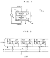
FIG. 1 is a diagram showing magnetic marks, coil arrays, a detection circuit, and a smoothing unit according to an embodiment. - [
FIG. 2 ]
FIG. 2 is a block diagram showing the coil array according to the embodiment. - [
FIG. 3 ]
FIG. 3 is a block diagram showing the detection circuit and the smoothing unit according to the embodiment. - [
FIG. 4 ]
FIG. 4 includes graphs showing smoothing at the time of switching the coil arrays and the weight w of each coil array. - [
FIG. 5 ]
FIG. 5 includes graphs showing prediction of the current position based on signals from coil arrays and smoothing. - [
FIG. 6 ]
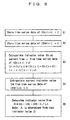
FIG. 6 is a flow chart showing an algorithm of smoothing. - [
FIG. 7 ]
FIG. 7 is a block diagram showing detection circuits and a smoothing unit according to a modified embodiment. - Hereinafter, an embodiment in the most preferred form for carrying out the present invention will be described. The scope of the invention shall be determined according to understanding of a person skilled in the art based on the description of the claims in consideration of the description of the specification and techniques known in this technical field.
-
FIGS. 1 to 7 show the embodiment. In the drawings, reference numerals m1, m2 denote magnetic marks provided along left and right sides of a travel rail for moving objects (not shown), e.g., overhead traveling vehicles in the embodiment. For example, the mark is a combination of magnetizable material and non-magnetizable material, or a permanent magnet or the like. Aposition detector 2 is attached to a moving object (not shown), and made up of a pair of left and right coil arrays L, R (left and right sensor units), a common alternating current power supply circuit for driving the coil arrays L, R, acommon detection circuit 6, and asmoothing unit 8. - The coil arrays L, R have the same structure. A layout of coils of the coil arrays L, R is shown in
FIG. 2 . For example, four coils C1-1 to C1-4 are arranged in one set, and likewise, coils C2-1 to C2-4 are arranged in one set, and coils C3-1 to C3-4 are arranged in one set. The other coils are arranged in the same manner. Two outputs are collected from four coils of each set as outputs P1, P2 of the coil arrays. Further, the coils C1-1 to C3-4 are arranged in series in the order of C1-1, C1-2, C1-3, C1-4, C2-1, C2-2, ... etc. -
FIG. 3 shows structure of adetection circuit 6 or the like. An alternating currentpower supply circuit 4 includes atimer 12 having a clock circuit, a table 13 for reading a signal corresponding to sinωt from thetimer 12, and a D/A converter 14 for performing D/A conversion of the outputs of the table 13 to output a signal a × sinωt corresponding to the alternating current waveform voltage. In thedetection circuit 6, timing where the alternating current signal sinωt becomes 0 is important. At this timing, thecounter 22 as described later is reset. In thedetection circuit 6, when sin(ωt + α) becomes 0, the clock outputs from thetimer 12 are latched, and the time ti is outputted. α denotes a phase relative to the mark, and denotes displacement based on the mark. The value obtained by adding an offset to α is an indicator value of positions of each sensor unit. - As shown in
FIG. 2 , a pair of signals P1, P2 are obtained from the coil arrays L, R. Since there are two sets of the coil arrays, two sets of signals (P1L, P2L), (P1R, P2R) are outputted to thedetection circuit 6. In thedetection circuit 6, the signals (P1L, P2L) and (P1F, P2R) are switched alternately by aswitch 16 for processing.Reference numerals operation amplifier 18 obtains a signal corresponding to b × cosα × sinωt, and theoperational amplifier 19 obtains a signal corresponding to b × sinα × sinωt. Aphase shifter 20 advances the phase of ωt of theoperational amplifier 19 by 90° to output a signal corresponding to b × sinα × cosωt. For this purpose, for example, the signal is delayed by π/2 of ωt, and negative to positive conversion or positive to negative conversion is performed. Anadder 21 adds the signal of b × cosα × sinωt from theoperational amplifier 18 to the signal of b × sinα × cosωt from thephase shifter 20, and outputs a signal corresponding to b × sin (ωt + α) using addition theorem. - α denotes a position of the coil array relative to the magnetic mark in the phase in a range of 0 to 2π, i.e., α is a position based on the magnetic mark. Each time sinωt becomes 0, the
counter 22 is reset by a signal from thetimer 12. Then, the time until sin(ωt + α) becomes 0 is counted. Conversely, the time until sinωt becomes 0 after sin(ωt + α) became 0 may be counted. Data of α is obtained from thecounter 22. Since this data is based on the magnetic mark, an offsetcorrection unit 30 performs offset correction of the data, and converts the data into an indicator value Di of positions of the moving object. The series of processing as described above is performed for left and right magnetic marks m1, m2 alternately. For the left magnetic mark m1, an indicator value DiL and time series data of the detection time tiL are obtained. For the right magnetic mark m2, an indicator value DiR and time series data of the detection time tiR are obtained. These two types of time series data are stored in amemory 31. - A
prediction computation unit 32 performs prediction computation of the current position DiL based on the coil array L using the time series data from the coil array L in thememory 31. Likewise, theprediction computation unit 32 performs prediction computation of the current position DiR based on the coil array R using the time series data from the coil array R. In a segment where only the coil array L is valid, prediction computation for only the current position based on the coil array L is performed. Likewise, in a segment where only the coil array R is valid, prediction computation for only the current position based on the coil array R is performed. Prediction computation is at least performed in a segment where both of the coil array L and the coil array R are valid (overlapping area). In the embodiment, weighted averaging is performed as smoothing. As shown inFIG. 4 , a smoothingunit 8 averages prediction computation values of two current values regarding the coil array L and the coil array R using X/L1 as a weight, and outputs an indicator value D of the current position. The meaning of X/L1 is shown inFIG. 4 . -
FIG. 4 shows smoothing of indicator values from the coil arrays L, R. On the left side inFIG. 4 , only the coil array L is valid. On the right side inFIG. 4 , only the coil array R is valid. A segment where both of the coil array L and the coil array R are valid is present between the left side and right side ofFIG. 4 . This segment is a target of smoothing. The length of the segment is L1. In this segment, smoothing is performed as shown by a double line inFIG. 4 . In this segment, indicator values are outputted from the coil arrays L, R at timings of vertical lines inFIG. 4 . Prediction computation of these indicator values are performed by the prediction computation unit to convert the indicator values into a continuous indicator value. The weight of the signal of the coil array L is 100% at the start of a segment where X= 0, and the weight of the signal of the coil array R is 100% at the end of a segment where X = L1. For example, the weight changes linearly between these points. -
FIG. 5 schematically shows processing from prediction computation to calculation of the indicator value after smoothing. A graph in an upper portion ofFIG. 5 shows the indicator value DL from the left coil array L. For example, the indicator value DL is generated in a cycle of about 10Hz of the alternating current power supply signal. Likewise, the indicator value DR from the right coil array R is generated in a cycle of about 10kHz. In the area where both of the two coil arrays are valid, since the detection circuit is switched alternately, the time interval of obtaining the indicator value is twice as large as the time interval in the other segment. Further, the indicator values from the pair of coils L, R cannot be obtained at the same time. Therefore, indicator values at arbitrary points are temporarily determined. Then, as shown in a graph in a lower portion ofFIG. 5 , the temporarily determined indicator values are averaged using the weight w to generate the indicator value D(t) at the time t. The weight w is X/L1. -
FIG. 6 shows a processing algorithm in the overlapping segment where both of the coil arrays L and R are valid. Instep 1, an indicator value from the coil array L and the time series data of the detection time are stored. Instep 2, outputs DR from the coil array R and time series data of the detection time are stored.Step 1 andstep 2 are performed alternately. In step 3, with respect to the coil array L, the indicator value DR at the current time r is determined by extrapolation of the time series data obtained from the coil array L. Likewise, instep 4, with respect to the coil array R, the indicator value DR at the current time is determined by extrapolation. Step 3 andStep 4 are performed alternately as well. Instep 5, the two extrapolated values are weight averaged to determine the current position. Determination of the relative position X in the overlapping segment is substantially equal to determination of indicator value D. For example, a value calculated from the previous indicator value D is used as X. In the case of carrying out processing more precisely, X is determined from the previous indicator value, and the current indicator value D is determined from X. Then, X is determined again based on the current indicator value D, and then, the current indicator value D is determined again. -
FIG. 7 shows detection circuits according to a modified embodiment. A pair of coil arrays L, R are driven by a common alternating current power supply circuit made up of thetimer 12, the table 13, and the D/A converter 14. In this respect, the circuit ofFIG. 7 is the same as that shown inFIG. 3 . In the circuit ofFIG. 7 , a pair of detection circuits are provided, and outputs from the separate detection circuits are smoothed by a smoothingunit 8 in accordance with the manner shown inFIG. 4 . Therefore, in an offset correction unit 30', offset correction of only one indicator value from one coil is performed. Further, since the indicator values from left and right coil arrays can be obtained substantially at the same time, prediction computation is omitted. In the circuit shown inFIG. 7 , the pair of detection circuits are required. Additionally, since the signals from the left and right coil arrays L, R are processed by the separate detection circuits, errors based on the variation in the characteristics of the detection circuits occur. In other respect, the detection circuit ofFIG. 7 are the same as thedetection circuit 6 shown inFIG. 3 . - In the embodiment, the following advantages are obtained.
- (1) In the overlapping segment where signals are obtained from both of the pair of coils, the outputs from the position detector do not change discontinuously. Therefore, no excessive load is applied to the servo system or the like using the signal from the position detector for control.
- (2) By determining the positional outputs as D = DL - (DL - DR) × X/L1, the position can be determined by simple computation. Further, the errors can be dispersed over the entire overlapping segment.
- (3) Sharing of the detection circuit is advantageous in terms of cost, and no errors due to variation of the detection circuit occur.
- (4) By predicting the current position based on the prediction computation unit, since the detection circuit is shared, it becomes possible to solve the problem that the left and right indicator values cannot be obtained at the same time. Further, the current indicator value can be predicted substantially at any position. Further, also in segments other than the overlapping segment, the indicator value can be outputted regardless of the alternating current cycle of driving the coil arrays.
- The components such as the offset
correction unit 30, thememory 31, theprediction computation unit 32, the smoothingunit 8, thetimer 12, the table 13, the D/A converter 14 may be provided as discrete circuits. Alternatively, these components may be provided as computer structure made up of hardware and software. -
- 2:
- position detector
- 4:
- alternating current power supply circuit
- 6:
- detection circuit
- 8:
- smoothing unit
- 10, 11:
- signal line
- 12:
- timer
- 13:
- table
- 14:
- D/A converter
- 16:
- switch
- 18, 19:
- operational amplifier
- 20:
- phase shifter
- 21:
- adder
- 22:
- counter
- 30:
- offset correction segment
- 31:
- memory
- 32:
- prediction computation segment
- m1, m2:
- magnetic mark
- L, R:
- coil array
- C1-1 to C3-4:
- coil
- D:
- indicator value
- t:
- time
- P1, P2:
- outputs of coil array
- L1:
- length of overlapping portion
- X:
- relative coordinate in overlapping portion
Claims (5)
- A position detector having a plurality of sensor units each configured to determine positions, the position detector selectively using the sensor units for outputting positions of a moving object,
the position detector including a smoothing unit for generating positional outputs indicating the positions of the moving object by combining outputs from the plurality of the sensor units in a segment where the plurality of sensor units output positions together and are valid, in such a way that the positional outputs change continuously from a start to an end of the segment. - The position detector according to claim 1, in the segment, the positional outputs D being determined based on an equation of D = DL-(DL-DR) × X/L1, where DL denotes positions based on outputs from a first sensor unit of the plurality of sensor units, DR denotes positions based on outputs from a second sensor unit of the plurality of sensor units, L1 denotes length of the segment along a moving direction of the moving object, X denotes relative positions of the moving object in the segment, X = 0 on a side where only the first sensor unit is valid, and X = L1 on a side where only the second sensor unit is valid.
- The position detector according to claim 1, the plurality of sensor units each comprising a coil array,
the position detector including:a common power supply for driving a plurality of coil arrays;a detection circuit for converting the outputs from the coil arrays into the positional outputs; anda switch for selectively inputting outputs from the plurality of coil arrays to the detection circuit in such a way that the detection circuit is shared between the plurality of coil arrays,the switch being switched in the segment to convert the outputs from the plurality of coil arrays alternately into the positional outputs by the detection circuit. - The position detector according to claim 3, a prediction computation unit being provided for extrapolating time series data of positions based on outputs from each coil array to positions at current time as the temporal current positions by each coil array,
in the smoothing unit, the temporal current positions by the coil arrays being combined to generate the positional outputs. - A position detection method by a position detector having a plurality of sensor units each configured to determine positions, the position detector selectively using the sensor units for outputting positions of a moving object, the method including the step of:generating positional outputs indicating the positions of the moving object with a smoothing unit in the position detector by combining outputs from the plurality of the sensor units in a segment where the plurality of sensor units output positions together and are valid, in such a way that the positional outputs to change continuously from a start to an end of the segment.
Applications Claiming Priority (1)
| Application Number | Priority Date | Filing Date | Title |
|---|---|---|---|
| JP2010091107A JP5007753B2 (en) | 2010-04-12 | 2010-04-12 | Position sensor |
Publications (2)
| Publication Number | Publication Date |
|---|---|
| EP2378241A1 true EP2378241A1 (en) | 2011-10-19 |
| EP2378241B1 EP2378241B1 (en) | 2016-08-31 |
Family
ID=44314204
Family Applications (1)
| Application Number | Title | Priority Date | Filing Date |
|---|---|---|---|
| EP11161184.4A Active EP2378241B1 (en) | 2010-04-12 | 2011-04-05 | Position detector and position detection method |
Country Status (7)
| Country | Link |
|---|---|
| US (1) | US8854034B2 (en) |
| EP (1) | EP2378241B1 (en) |
| JP (1) | JP5007753B2 (en) |
| KR (1) | KR101420118B1 (en) |
| CN (1) | CN102235883B (en) |
| SG (1) | SG175500A1 (en) |
| TW (1) | TWI493308B (en) |
Cited By (1)
| Publication number | Priority date | Publication date | Assignee | Title |
|---|---|---|---|---|
| CN103688227A (en) * | 2011-07-22 | 2014-03-26 | 村田机械株式会社 | Mobile body system and walking control method of the mobile body |
Families Citing this family (8)
| Publication number | Priority date | Publication date | Assignee | Title |
|---|---|---|---|---|
| JP4835960B2 (en) | 2009-04-24 | 2011-12-14 | 村田機械株式会社 | Mobile system |
| JP6377335B2 (en) * | 2013-10-28 | 2018-08-22 | 日本電産サンキョー株式会社 | Data detection method and detection device in detection device |
| JP7438660B2 (en) | 2017-11-30 | 2024-02-27 | キヤノン株式会社 | Conveyance systems, conveyance methods, and article manufacturing methods |
| EP3706297A1 (en) * | 2019-03-07 | 2020-09-09 | B&R Industrial Automation GmbH | Method for controlling a long stator linear motor |
| CN114067546B (en) * | 2020-07-29 | 2023-04-18 | 深圳绿米联创科技有限公司 | Position detection method and device and electronic equipment |
| JP7455694B2 (en) | 2020-07-29 | 2024-03-26 | 株式会社Fuji | Mobile object control method and mobile object control system |
| US12276768B2 (en) * | 2020-08-12 | 2025-04-15 | Selskabet Af 6. April 2010 Aps | Suspension of electromagnetic receiver coil |
| KR102293015B1 (en) | 2021-03-24 | 2021-08-24 | 주식회사 비카누스 | Path and sensor data matching system based on spatial information |
Citations (5)
| Publication number | Priority date | Publication date | Assignee | Title |
|---|---|---|---|---|
| US4589038A (en) * | 1983-07-14 | 1986-05-13 | Honeywell Gmbh | Position sensor |
| US20080113102A1 (en) * | 2006-11-13 | 2008-05-15 | Takashi Arai | Agents for the surface treatment of zinc or zinc alloy products |
| JP2008140144A (en) | 2006-12-01 | 2008-06-19 | Murata Mach Ltd | Traveling cart and its system |
| US20080238413A1 (en) * | 2007-03-26 | 2008-10-02 | General Electric Company | Electromagnetic tracking method and system |
| JP2009002660A (en) | 2007-06-19 | 2009-01-08 | Murata Mach Ltd | Linear scale |
Family Cites Families (12)
| Publication number | Priority date | Publication date | Assignee | Title |
|---|---|---|---|---|
| JP2648181B2 (en) * | 1988-08-31 | 1997-08-27 | オ−クマ株式会社 | Linear encoder |
| US5311116A (en) * | 1992-04-02 | 1994-05-10 | Electronic Development, Inc. | Multi-channel electromagnetically transparent voltage waveform monitor link |
| JP4043793B2 (en) * | 2002-01-31 | 2008-02-06 | オークマ株式会社 | Mobile device |
| US6910657B2 (en) * | 2003-05-30 | 2005-06-28 | Raytheon Company | System and method for locating a target and guiding a vehicle toward the target |
| JP4027345B2 (en) | 2004-05-24 | 2007-12-26 | ファナック株式会社 | Optical encoder |
| US7432497B2 (en) * | 2005-09-29 | 2008-10-07 | Mitutoyo Corporation | Absolute linear encoder |
| GB2432063B (en) * | 2005-11-01 | 2009-09-09 | Zetex Semiconductors Plc | A multiplexer |
| JP4214533B2 (en) * | 2006-08-10 | 2009-01-28 | 村田機械株式会社 | Mobile system |
| JP4217918B2 (en) * | 2006-11-28 | 2009-02-04 | 村田機械株式会社 | Mobile system |
| JP2009014454A (en) * | 2007-07-03 | 2009-01-22 | Tokai Rika Co Ltd | Position detection device |
| JP4922338B2 (en) * | 2008-04-25 | 2012-04-25 | エーエスエムエル ネザーランズ ビー.ブイ. | Position control system, lithographic apparatus, and method for controlling the position of a movable object |
| JP4438882B2 (en) * | 2008-05-12 | 2010-03-24 | 村田機械株式会社 | Mobile system |
-
2010
- 2010-04-12 JP JP2010091107A patent/JP5007753B2/en active Active
-
2011
- 2011-03-25 CN CN201110080184.3A patent/CN102235883B/en active Active
- 2011-03-28 SG SG2011021672A patent/SG175500A1/en unknown
- 2011-03-28 KR KR1020110027795A patent/KR101420118B1/en active Active
- 2011-04-05 EP EP11161184.4A patent/EP2378241B1/en active Active
- 2011-04-06 US US13/080,920 patent/US8854034B2/en active Active
- 2011-04-11 TW TW100112392A patent/TWI493308B/en active
Patent Citations (5)
| Publication number | Priority date | Publication date | Assignee | Title |
|---|---|---|---|---|
| US4589038A (en) * | 1983-07-14 | 1986-05-13 | Honeywell Gmbh | Position sensor |
| US20080113102A1 (en) * | 2006-11-13 | 2008-05-15 | Takashi Arai | Agents for the surface treatment of zinc or zinc alloy products |
| JP2008140144A (en) | 2006-12-01 | 2008-06-19 | Murata Mach Ltd | Traveling cart and its system |
| US20080238413A1 (en) * | 2007-03-26 | 2008-10-02 | General Electric Company | Electromagnetic tracking method and system |
| JP2009002660A (en) | 2007-06-19 | 2009-01-08 | Murata Mach Ltd | Linear scale |
Cited By (2)
| Publication number | Priority date | Publication date | Assignee | Title |
|---|---|---|---|---|
| CN103688227A (en) * | 2011-07-22 | 2014-03-26 | 村田机械株式会社 | Mobile body system and walking control method of the mobile body |
| CN103688227B (en) * | 2011-07-22 | 2017-03-15 | 村田机械株式会社 | Mobile body system and walking control method of the mobile body |
Also Published As
| Publication number | Publication date |
|---|---|
| CN102235883B (en) | 2015-09-09 |
| KR20110114442A (en) | 2011-10-19 |
| CN102235883A (en) | 2011-11-09 |
| TW201144960A (en) | 2011-12-16 |
| EP2378241B1 (en) | 2016-08-31 |
| TWI493308B (en) | 2015-07-21 |
| JP5007753B2 (en) | 2012-08-22 |
| US20110248707A1 (en) | 2011-10-13 |
| JP2011220874A (en) | 2011-11-04 |
| KR101420118B1 (en) | 2014-07-16 |
| US8854034B2 (en) | 2014-10-07 |
| SG175500A1 (en) | 2011-11-28 |
Similar Documents
| Publication | Publication Date | Title |
|---|---|---|
| EP2378241B1 (en) | Position detector and position detection method | |
| CN102804566B (en) | Position detection device for movable magnet type linear motor | |
| US8294391B2 (en) | Moving body system and method of determining initial position of moving body | |
| KR101610473B1 (en) | Apparatus and method for compensating for position error of resolver | |
| US20110109252A1 (en) | Linear scale, linear motor, and linear motor controller | |
| US9455650B2 (en) | Two-dimensional locating method of motion platform based on magnetic steel array | |
| US20160041005A1 (en) | Magnetic Position Sensor and Position Detecting Method | |
| JP2013025639A (en) | Moving body system and traveling control method for moving body | |
| TWI611163B (en) | Displacement sensor and displacement detection method | |
| CN113710997B (en) | Magnetic sensing system, detection device and magnetic interference biasing method | |
| CN113272627A (en) | Position sensor for long-stroke linear permanent magnet motor | |
| JP5783410B2 (en) | MOBILE SYSTEM AND MOBILE POSITION DETECTING METHOD | |
| EP2559970B1 (en) | Displacement sensor and method for detecting displacement | |
| JP2007171081A (en) | Position detection method | |
| KR20130114455A (en) | A system for detecting position and velocity of motor | |
| JP2023041534A (en) | magnetic encoder | |
| JP2004028623A (en) | Slide position detection device and xy table using the same | |
| JPH0287071A (en) | Detecting device of speed |
Legal Events
| Date | Code | Title | Description |
|---|---|---|---|
| AK | Designated contracting states |
Kind code of ref document: A1 Designated state(s): AL AT BE BG CH CY CZ DE DK EE ES FI FR GB GR HR HU IE IS IT LI LT LU LV MC MK MT NL NO PL PT RO RS SE SI SK SM TR |
|
| AX | Request for extension of the european patent |
Extension state: BA ME |
|
| PUAI | Public reference made under article 153(3) epc to a published international application that has entered the european phase |
Free format text: ORIGINAL CODE: 0009012 |
|
| 17P | Request for examination filed |
Effective date: 20120418 |
|
| 17Q | First examination report despatched |
Effective date: 20150710 |
|
| GRAP | Despatch of communication of intention to grant a patent |
Free format text: ORIGINAL CODE: EPIDOSNIGR1 |
|
| INTG | Intention to grant announced |
Effective date: 20160324 |
|
| GRAS | Grant fee paid |
Free format text: ORIGINAL CODE: EPIDOSNIGR3 |
|
| GRAA | (expected) grant |
Free format text: ORIGINAL CODE: 0009210 |
|
| AK | Designated contracting states |
Kind code of ref document: B1 Designated state(s): AL AT BE BG CH CY CZ DE DK EE ES FI FR GB GR HR HU IE IS IT LI LT LU LV MC MK MT NL NO PL PT RO RS SE SI SK SM TR |
|
| REG | Reference to a national code |
Ref country code: CH Ref legal event code: EP Ref country code: GB Ref legal event code: FG4D |
|
| REG | Reference to a national code |
Ref country code: IE Ref legal event code: FG4D |
|
| REG | Reference to a national code |
Ref country code: DE Ref legal event code: R096 Ref document number: 602011029757 Country of ref document: DE |
|
| REG | Reference to a national code |
Ref country code: AT Ref legal event code: REF Ref document number: 825382 Country of ref document: AT Kind code of ref document: T Effective date: 20161015 |
|
| REG | Reference to a national code |
Ref country code: LT Ref legal event code: MG4D |
|
| REG | Reference to a national code |
Ref country code: NL Ref legal event code: MP Effective date: 20160831 |
|
| REG | Reference to a national code |
Ref country code: AT Ref legal event code: MK05 Ref document number: 825382 Country of ref document: AT Kind code of ref document: T Effective date: 20160831 |
|
| PG25 | Lapsed in a contracting state [announced via postgrant information from national office to epo] |
Ref country code: RS Free format text: LAPSE BECAUSE OF FAILURE TO SUBMIT A TRANSLATION OF THE DESCRIPTION OR TO PAY THE FEE WITHIN THE PRESCRIBED TIME-LIMIT Effective date: 20160831 Ref country code: HR Free format text: LAPSE BECAUSE OF FAILURE TO SUBMIT A TRANSLATION OF THE DESCRIPTION OR TO PAY THE FEE WITHIN THE PRESCRIBED TIME-LIMIT Effective date: 20160831 Ref country code: NO Free format text: LAPSE BECAUSE OF FAILURE TO SUBMIT A TRANSLATION OF THE DESCRIPTION OR TO PAY THE FEE WITHIN THE PRESCRIBED TIME-LIMIT Effective date: 20161130 Ref country code: FI Free format text: LAPSE BECAUSE OF FAILURE TO SUBMIT A TRANSLATION OF THE DESCRIPTION OR TO PAY THE FEE WITHIN THE PRESCRIBED TIME-LIMIT Effective date: 20160831 Ref country code: LT Free format text: LAPSE BECAUSE OF FAILURE TO SUBMIT A TRANSLATION OF THE DESCRIPTION OR TO PAY THE FEE WITHIN THE PRESCRIBED TIME-LIMIT Effective date: 20160831 |
|
| PG25 | Lapsed in a contracting state [announced via postgrant information from national office to epo] |
Ref country code: SE Free format text: LAPSE BECAUSE OF FAILURE TO SUBMIT A TRANSLATION OF THE DESCRIPTION OR TO PAY THE FEE WITHIN THE PRESCRIBED TIME-LIMIT Effective date: 20160831 Ref country code: LV Free format text: LAPSE BECAUSE OF FAILURE TO SUBMIT A TRANSLATION OF THE DESCRIPTION OR TO PAY THE FEE WITHIN THE PRESCRIBED TIME-LIMIT Effective date: 20160831 Ref country code: AT Free format text: LAPSE BECAUSE OF FAILURE TO SUBMIT A TRANSLATION OF THE DESCRIPTION OR TO PAY THE FEE WITHIN THE PRESCRIBED TIME-LIMIT Effective date: 20160831 Ref country code: ES Free format text: LAPSE BECAUSE OF FAILURE TO SUBMIT A TRANSLATION OF THE DESCRIPTION OR TO PAY THE FEE WITHIN THE PRESCRIBED TIME-LIMIT Effective date: 20160831 Ref country code: GR Free format text: LAPSE BECAUSE OF FAILURE TO SUBMIT A TRANSLATION OF THE DESCRIPTION OR TO PAY THE FEE WITHIN THE PRESCRIBED TIME-LIMIT Effective date: 20161201 Ref country code: NL Free format text: LAPSE BECAUSE OF FAILURE TO SUBMIT A TRANSLATION OF THE DESCRIPTION OR TO PAY THE FEE WITHIN THE PRESCRIBED TIME-LIMIT Effective date: 20160831 |
|
| PG25 | Lapsed in a contracting state [announced via postgrant information from national office to epo] |
Ref country code: RO Free format text: LAPSE BECAUSE OF FAILURE TO SUBMIT A TRANSLATION OF THE DESCRIPTION OR TO PAY THE FEE WITHIN THE PRESCRIBED TIME-LIMIT Effective date: 20160831 Ref country code: EE Free format text: LAPSE BECAUSE OF FAILURE TO SUBMIT A TRANSLATION OF THE DESCRIPTION OR TO PAY THE FEE WITHIN THE PRESCRIBED TIME-LIMIT Effective date: 20160831 |
|
| PG25 | Lapsed in a contracting state [announced via postgrant information from national office to epo] |
Ref country code: PL Free format text: LAPSE BECAUSE OF FAILURE TO SUBMIT A TRANSLATION OF THE DESCRIPTION OR TO PAY THE FEE WITHIN THE PRESCRIBED TIME-LIMIT Effective date: 20160831 Ref country code: DK Free format text: LAPSE BECAUSE OF FAILURE TO SUBMIT A TRANSLATION OF THE DESCRIPTION OR TO PAY THE FEE WITHIN THE PRESCRIBED TIME-LIMIT Effective date: 20160831 Ref country code: PT Free format text: LAPSE BECAUSE OF FAILURE TO SUBMIT A TRANSLATION OF THE DESCRIPTION OR TO PAY THE FEE WITHIN THE PRESCRIBED TIME-LIMIT Effective date: 20170102 Ref country code: SK Free format text: LAPSE BECAUSE OF FAILURE TO SUBMIT A TRANSLATION OF THE DESCRIPTION OR TO PAY THE FEE WITHIN THE PRESCRIBED TIME-LIMIT Effective date: 20160831 Ref country code: BG Free format text: LAPSE BECAUSE OF FAILURE TO SUBMIT A TRANSLATION OF THE DESCRIPTION OR TO PAY THE FEE WITHIN THE PRESCRIBED TIME-LIMIT Effective date: 20161130 Ref country code: BE Free format text: LAPSE BECAUSE OF FAILURE TO SUBMIT A TRANSLATION OF THE DESCRIPTION OR TO PAY THE FEE WITHIN THE PRESCRIBED TIME-LIMIT Effective date: 20160831 Ref country code: SM Free format text: LAPSE BECAUSE OF FAILURE TO SUBMIT A TRANSLATION OF THE DESCRIPTION OR TO PAY THE FEE WITHIN THE PRESCRIBED TIME-LIMIT Effective date: 20160831 Ref country code: CZ Free format text: LAPSE BECAUSE OF FAILURE TO SUBMIT A TRANSLATION OF THE DESCRIPTION OR TO PAY THE FEE WITHIN THE PRESCRIBED TIME-LIMIT Effective date: 20160831 |
|
| REG | Reference to a national code |
Ref country code: DE Ref legal event code: R097 Ref document number: 602011029757 Country of ref document: DE |
|
| PG25 | Lapsed in a contracting state [announced via postgrant information from national office to epo] |
Ref country code: IT Free format text: LAPSE BECAUSE OF FAILURE TO SUBMIT A TRANSLATION OF THE DESCRIPTION OR TO PAY THE FEE WITHIN THE PRESCRIBED TIME-LIMIT Effective date: 20160831 |
|
| PLBE | No opposition filed within time limit |
Free format text: ORIGINAL CODE: 0009261 |
|
| STAA | Information on the status of an ep patent application or granted ep patent |
Free format text: STATUS: NO OPPOSITION FILED WITHIN TIME LIMIT |
|
| 26N | No opposition filed |
Effective date: 20170601 |
|
| PG25 | Lapsed in a contracting state [announced via postgrant information from national office to epo] |
Ref country code: SI Free format text: LAPSE BECAUSE OF FAILURE TO SUBMIT A TRANSLATION OF THE DESCRIPTION OR TO PAY THE FEE WITHIN THE PRESCRIBED TIME-LIMIT Effective date: 20160831 |
|
| REG | Reference to a national code |
Ref country code: CH Ref legal event code: PL |
|
| GBPC | Gb: european patent ceased through non-payment of renewal fee |
Effective date: 20170405 |
|
| REG | Reference to a national code |
Ref country code: IE Ref legal event code: MM4A |
|
| REG | Reference to a national code |
Ref country code: FR Ref legal event code: ST Effective date: 20171229 |
|
| PG25 | Lapsed in a contracting state [announced via postgrant information from national office to epo] |
Ref country code: FR Free format text: LAPSE BECAUSE OF NON-PAYMENT OF DUE FEES Effective date: 20170502 Ref country code: MC Free format text: LAPSE BECAUSE OF FAILURE TO SUBMIT A TRANSLATION OF THE DESCRIPTION OR TO PAY THE FEE WITHIN THE PRESCRIBED TIME-LIMIT Effective date: 20160831 |
|
| PG25 | Lapsed in a contracting state [announced via postgrant information from national office to epo] |
Ref country code: LU Free format text: LAPSE BECAUSE OF NON-PAYMENT OF DUE FEES Effective date: 20170405 Ref country code: GB Free format text: LAPSE BECAUSE OF NON-PAYMENT OF DUE FEES Effective date: 20170405 Ref country code: LI Free format text: LAPSE BECAUSE OF NON-PAYMENT OF DUE FEES Effective date: 20170430 Ref country code: CH Free format text: LAPSE BECAUSE OF NON-PAYMENT OF DUE FEES Effective date: 20170430 |
|
| PG25 | Lapsed in a contracting state [announced via postgrant information from national office to epo] |
Ref country code: IE Free format text: LAPSE BECAUSE OF NON-PAYMENT OF DUE FEES Effective date: 20170405 |
|
| PG25 | Lapsed in a contracting state [announced via postgrant information from national office to epo] |
Ref country code: MT Free format text: LAPSE BECAUSE OF NON-PAYMENT OF DUE FEES Effective date: 20170405 |
|
| PG25 | Lapsed in a contracting state [announced via postgrant information from national office to epo] |
Ref country code: AL Free format text: LAPSE BECAUSE OF FAILURE TO SUBMIT A TRANSLATION OF THE DESCRIPTION OR TO PAY THE FEE WITHIN THE PRESCRIBED TIME-LIMIT Effective date: 20160831 |
|
| PG25 | Lapsed in a contracting state [announced via postgrant information from national office to epo] |
Ref country code: HU Free format text: LAPSE BECAUSE OF FAILURE TO SUBMIT A TRANSLATION OF THE DESCRIPTION OR TO PAY THE FEE WITHIN THE PRESCRIBED TIME-LIMIT; INVALID AB INITIO Effective date: 20110405 |
|
| PG25 | Lapsed in a contracting state [announced via postgrant information from national office to epo] |
Ref country code: CY Free format text: LAPSE BECAUSE OF NON-PAYMENT OF DUE FEES Effective date: 20160831 |
|
| PG25 | Lapsed in a contracting state [announced via postgrant information from national office to epo] |
Ref country code: MK Free format text: LAPSE BECAUSE OF FAILURE TO SUBMIT A TRANSLATION OF THE DESCRIPTION OR TO PAY THE FEE WITHIN THE PRESCRIBED TIME-LIMIT Effective date: 20160831 |
|
| PG25 | Lapsed in a contracting state [announced via postgrant information from national office to epo] |
Ref country code: TR Free format text: LAPSE BECAUSE OF FAILURE TO SUBMIT A TRANSLATION OF THE DESCRIPTION OR TO PAY THE FEE WITHIN THE PRESCRIBED TIME-LIMIT Effective date: 20160831 |
|
| PG25 | Lapsed in a contracting state [announced via postgrant information from national office to epo] |
Ref country code: IS Free format text: LAPSE BECAUSE OF FAILURE TO SUBMIT A TRANSLATION OF THE DESCRIPTION OR TO PAY THE FEE WITHIN THE PRESCRIBED TIME-LIMIT Effective date: 20161231 |
|
| PGFP | Annual fee paid to national office [announced via postgrant information from national office to epo] |
Ref country code: DE Payment date: 20250319 Year of fee payment: 15 |