EP2378135B1 - Differential sequence hydraulic valve - Google Patents
Differential sequence hydraulic valve Download PDFInfo
- Publication number
- EP2378135B1 EP2378135B1 EP20110162339 EP11162339A EP2378135B1 EP 2378135 B1 EP2378135 B1 EP 2378135B1 EP 20110162339 EP20110162339 EP 20110162339 EP 11162339 A EP11162339 A EP 11162339A EP 2378135 B1 EP2378135 B1 EP 2378135B1
- Authority
- EP
- European Patent Office
- Prior art keywords
- valve
- slide
- pressure
- fact
- port
- Prior art date
- Legal status (The legal status is an assumption and is not a legal conclusion. Google has not performed a legal analysis and makes no representation as to the accuracy of the status listed.)
- Not-in-force
Links
- 230000003247 decreasing effect Effects 0.000 claims description 21
- 230000036316 preload Effects 0.000 claims description 7
- 230000007704 transition Effects 0.000 claims 1
- 238000013459 approach Methods 0.000 description 6
- 238000010586 diagram Methods 0.000 description 6
- 238000006073 displacement reaction Methods 0.000 description 5
- 230000000694 effects Effects 0.000 description 4
- 230000007423 decrease Effects 0.000 description 2
- 238000007599 discharging Methods 0.000 description 1
- 238000000227 grinding Methods 0.000 description 1
- 238000003801 milling Methods 0.000 description 1
- 230000001737 promoting effect Effects 0.000 description 1
- 238000007789 sealing Methods 0.000 description 1
- 239000002699 waste material Substances 0.000 description 1
Images



Classifications
-
- F—MECHANICAL ENGINEERING; LIGHTING; HEATING; WEAPONS; BLASTING
- F15—FLUID-PRESSURE ACTUATORS; HYDRAULICS OR PNEUMATICS IN GENERAL
- F15B—SYSTEMS ACTING BY MEANS OF FLUIDS IN GENERAL; FLUID-PRESSURE ACTUATORS, e.g. SERVOMOTORS; DETAILS OF FLUID-PRESSURE SYSTEMS, NOT OTHERWISE PROVIDED FOR
- F15B13/00—Details of servomotor systems ; Valves for servomotor systems
- F15B13/02—Fluid distribution or supply devices characterised by their adaptation to the control of servomotors
- F15B13/04—Fluid distribution or supply devices characterised by their adaptation to the control of servomotors for use with a single servomotor
- F15B13/042—Fluid distribution or supply devices characterised by their adaptation to the control of servomotors for use with a single servomotor operated by fluid pressure
Definitions
- the present invention relates to the field of the differential sequence hydraulic valves having a double adjustment which manage the opening and closure of an oil passage between two ports of the valve, based on an outer pressure signal acting on the piloting port of the valve itself.
- sequence valves are used in systems in which the event order is determined by the pressure in the circuit itself.
- a possible application is in the load sensing hydraulic circuits dedicated to the management of a differential load of an accumulator.
- a second possible application refers to the low flow rate hydraulic systems supplied by an accumulator loaded by a fixed-displacement pump.
- the valve in such circuit, has the function of discharging the flow rate of the same pump when the accumulator is loaded.
- a third possible application refers to the low flow rate hydraulic systems having a fixed-displacement dedicated to the management of a differential load of an accumulator.
- the valve in object suitably inserted in such types of circuits, enables to increase the hydraulic circuit pressure in order to load an accumulator to a pressure value predetermined by the increasing adjustment of the valve itself.
- the part of the circuit supplied by the accumulator works between two pressure levels determined by a differential typical of the valve in object.
- sequence valves characterized by different double increasing and decreasing adjustment pressures, whose detailed description will be given in the following.
- pilot outer drainage valves characterized by a main stage which, in the rest position, closes the oil passage between the ports and by a double adjustment pilot stage.
- Such valve must be coupled to a logic element, which determines the closure and opening of the passage for the oil delivered by the pump.
- Both the described valves have been designed to work in systems requiring high working flow rate, but they are not adapted to work in load sensing circuits, both with a LS pump, and with a pressure compensator.
- the sizes of the oil passages in the above described systems are not adapted to manage a flow rate signal as required in this type of system.
- the piloted systems are instable with low work flow rates and a response time longer than the one of a direct operation approach.
- a differential sequence hydraulic valve according the preamble of the claim 1 is known from EP1906030 .
- Another object of the present invention is to provide a differential sequence double adjustment valve having a compact arrangement and reduced exchanging times.
- the valve operates by opening (if it is normally closed) or closing (if it is normally opened) the passage between the two ways dedicated to the oil flow.
- the increasing adjustment pressure value is always greater than the one of the decreasing adjustment pressure and the ratio between the two values is determined by the differential valve.
- the valve is branched with respect to the main line supplied by the pump.
- the valve in such circuit is branched with respect to the main line supplied by the pump and it discharges the flow rate of the same pump, when the accumulator is loaded.
- the valve is in series to the pump.
- the hydraulic diagram of an example of application of the four-way outer drainage valve is shown; said valve is characterized by a main stage, which, in the rest position, closes the oil passage between the ports 1 and 2 and a pilot double adjustment stage (see also Figure 4.1 ).
- the pilot stage When the pilot pressure, during the pressure increase, reaches the increasing adjustment pressure, the pilot stage operates by driving the main stage which opens the passage between the ports 1 and 2.
- the pilot stage operates by closing the main stage, restoring the rest condition.
- valve is used in circuits managing a differential load of an hydraulic accumulator.
- the valve determines a deliver pressure increase, in order to enable the loading of the accumulator, when the valve is in a closed rest position, in other words it is not piloted.
- valve is opened, when the pressure in the accumulator is greater than the decreasing adjustment pressure.
- valve also if opened, throttles the passage by forming a power loss.
- the valve In order to reduce at the maximum such loss, it is necessary to have large oil passages.
- a main disadvantage of this kind of valve is due to the fact that for keeping switched the same, it is necessary to have a continuous passage of oil from the port 1 to the drainage port 4 and this causes a flow rate loss and consequently a power loss.
- valve is not adapted to work with load sensing circuits, both with a LS pump and a pressure compensator; for said circuits (whose application is shown in Figure 1.1 ) it is necessary to act on the signal LS for managing the load of the accumulator and it is not necessary to have any valve in series to the pump. Particularly, it is necessary to connect the pressure main line to the line LS in order to have the greatest flow rate and pressure in order to load the accumulator.
- valve When the accumulator is loaded, the valve must close again for interrupting the passage connecting the pump to its signal LS.
- Figure 2.2 illustrates the hydraulic circuit of an example of application of the outer piloting three-way valve; (see also Figure 4.2 ).
- Such valve substantially comprises a valve pilot stage of Figure 4.1 (described before) and it is normally coupled to a logic element.
- Such approach enables to obtain high work flow rates in the system, by always draining the drainage oil through the described valve in order to keep opened the logic element.
- a further disadvantage for both the described approaches is due to the fact that the sizes of the oil passages, typical of the cited circuits, formed by a main element and a pilot stage, are not adapted to manage a low flow rate signal as required by this kind of circuit.
- the pilot systems are instable in presence of low working flow rates and have response time greater than the one of a direct operation approach.
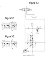
- Figure 3.1 illustrates the hydraulic complete symbol of the invention in a normally closed version
- Figure3.2 illustrates the complete hydraulic symbol of the invention in a normally opened version.
- Figure 3.3 shows the hydraulic diagram of a typical application of the valve, in other words a load sensing circuit managing the differential load of an accumulator.
- Figure 5.1 instead illustrates a cross-section of the valve of the invention, in a normally opened version with highlighted different details of the same.
- Figure 5.2 - 5.5 illustrate the valve in the different positions which it takes during the switching.
- the invention refers to a direct slide four-ways differential double adjustment valve having an outer pilot, normally opened or normally closed, wherein:
- the value of the adjustment increasing pressure is always greater than the one of the adjustment decreasing pressure and the ratio between such values is determined by the valve differential.
- FIG. 5.1 A cross-section of the valve, generally indicated at 20, in a normally opened version is shown in Figure 5.1 , while the corresponding hydraulic diagram is shown in Figure 3.2 .
- number 1 indicates the piloting port of the valve 20
- number 2 indicates the flow rate passage inlet port
- number 3 indicates the flow rate passage outlet port
- number 4 indicates the drainage port of the same, which must be connected to the drain.
- number 6 indicates the cartridge of the valve in which a slide 5 moves, having a pushing area A5.
- number 8 indicates the piston having a pushing area A8, moving inside the bushing 9.
- the bushing 9 is coaxial with respect to the cartridge, so that to enable the piston 8 and the slide 5 to axially move abutting one against the other in the inner gauged hole.
- Number 7 indicates the secondary spring having the function of keeping together the two components 5 and 8 during the operation.
- Number 11 indicates resilient means, in the example a main spring, acting on the outer end of the piston 8 (that is opposed to the slide 5), used for generating a force opposing to the piloting pressure, in order to obtain the desired adjustment pressure of the valve, while 12 indicates the registering screw used for precharging the spring 11.
- Number 10 indicates the spring-holder, the cartridge 6 is coupled to it by a thread and a calking not shown in the figure.
- the switching of the valve 20, to the normally opened arrangement occurs when the connection between the ports 2 and 3 is interrupted due to the closure of the holes crown present on the port 2 of the cartridge 6, by the corner S2 present on the slide 5 (see also Figure 5.3 ).
- valve 20 differential that is the ratio between the increasing adjustment and the decreasing adjustment, is given by the ratio between these two pushing areas.
- Figure 5.1 illustrates the valve in the rest arrangement, that is without a pressure on the piloting port 1.
- the slide 5 is balanced because the port 1 and the chamber C are at the same pressure p1.
- the piston 8 is subjected to the pressure p1 present in the chamber C and to the drainage pressure present in chamber D.
- the piston 8 does not move until the pressure p1 does not generate a force such to balance the spring 11 force, at the same time the slide 5 remains stopped due to the secondary spring 7 action which keeps it integral to the piston 8.
- the piston 8 is now balanced (chambers C and D are both at the drainage pressure), while the slide 5 is at pressure p1 at the port 1 and at the drainage pressure in chamber C.
- the force opposing the main spring 11 increases because with the same pressure p1, the pushing area passes from the value A8 of the piston to the greater value A5 of the slide.
- the increasing pilot pressure value equals the preload force of the spring seen in the Figure 5.2 arrangement, divided by the piston area A8; as soon as it is passed this position, it is lost the equilibrium condition on the slide so that it is quickly pushed to the stop.
- this port is closed (see Figure 5.5 ).
- the port 1 is connected to the drainage only during the switching from the position shown in Figure 5.2 to the one shown in Figure 5.4 .
- the presence of the drainage port 4 is provided for taking the pressure of the same drainage in chamber C in order to promote the described switching of the valve and to avoid the counter pressure in chamber D of the spring space.
- the valve having reached the stop position, remains in this position until the port 1 pressure reaches the decreasing pressure value of the valve 20.
- Such pressure value as it will be shown, equals the spring preload force seen in the Figure 5.4 arrangement, divided by the slide area A8.
- valve port 1 is still isolated (the overlapping is absent) both from chamber B and chamber C which are at the drainage pressure.
- the slide 5 is pushed by the pressure p1 on the area A5 and is balanced by the spring 11 force. Since area A5 is greater than the piston area A8, the equilibrium pressure is less than the adjustment increasing pressure of the valve 20.
- the pressure level is less than the value of the increasing adjustment, so that, once again, the slide-piston assembly is not in equilibrium, because the spring 11 force is greater than the pressure p1 value (it is equal to the decreasing adjustment pressure) multiplied by the area of the piston A8.
- the switching operation is generated when the port 2 is still closed (see Figure 5.4 ). Instead, at rest, this port is opened (see Figure 5.1 ).
- the described switching operation of the normally opened valve 20 is the same as the one of the normally closed valve 20, the difference being that the passage between the ports 2 is located at the opposed logic state in each arrangement of the valve (see Figures 5.1 - 5.5 ).
- Figure 5.1 illustrates the flap D used for reducing the effect of the flow forces at the opening of the port on the port 2 of the valve 20.
- the flow forces effect can also appear at the opening of the shoulders S1 and S3.
- Such holes modify the speed at which the chambers B and C can modify their pressure level, particularly by passing from the drainage pressure to the one of the piloting port 1.
- a further possible action enabling to modify such switching times consists of inserting a further dowel in position G in Figure 5.1 , which for the sake of simplicity has been represented by a broken line square inside the conduit to chamber B.
- holes F1, F2 and/or dowel G By changing the size of holes F1, F2 and/or dowel G, enables to optimize the switching times in order to improve the system stability in which the valve is inserted.
- the main advantage of maintaining separated the components is due to the fact that it is not necessary to have a coaxial thrust between the inner diameter of the bushing 9 and the cartridge 6, the slide 5 and the piston 8 must freely slide in these areas.
- a further advantage is due to the fact that the grinding of a single component on two diameters is certainly more complex than the one on two separate components.
- a further constructive variant can be implemented by inserting drilled dowels inside the slide 5 instead of the adjusted holes F1, F2 (adapted to communicate the inner chambers B and C with the ports 1 and 4), for more easily adapting the valve 20 to the different needs of the system in which the valve is located, without modifying the shape of the slide.
Landscapes
- Engineering & Computer Science (AREA)
- Physics & Mathematics (AREA)
- Fluid Mechanics (AREA)
- Mechanical Engineering (AREA)
- General Engineering & Computer Science (AREA)
- Fluid-Pressure Circuits (AREA)
- Multiple-Way Valves (AREA)
Description
- The present invention relates to the field of the differential sequence hydraulic valves having a double adjustment which manage the opening and closure of an oil passage between two ports of the valve, based on an outer pressure signal acting on the piloting port of the valve itself.
- As said, generally the sequence valves are used in systems in which the event order is determined by the pressure in the circuit itself.
- A possible application is in the load sensing hydraulic circuits dedicated to the management of a differential load of an accumulator.
- A second possible application refers to the low flow rate hydraulic systems supplied by an accumulator loaded by a fixed-displacement pump. The valve, in such circuit, has the function of discharging the flow rate of the same pump when the accumulator is loaded.
- A third possible application refers to the low flow rate hydraulic systems having a fixed-displacement dedicated to the management of a differential load of an accumulator.
- The valve in object, suitably inserted in such types of circuits, enables to increase the hydraulic circuit pressure in order to load an accumulator to a pressure value predetermined by the increasing adjustment of the valve itself.
- When the accumulator pressure decreases below a specific pressure value, equals to the decreasing adjustment pressure of the valve, the valve itself operates by determining again the accumulator load.
- Therefore, the part of the circuit supplied by the accumulator works between two pressure levels determined by a differential typical of the valve in object.
- There are known different types of sequence valves characterized by different double increasing and decreasing adjustment pressures, whose detailed description will be given in the following. Particularly, there are four-way pilot outer drainage valves, characterized by a main stage which, in the rest position, closes the oil passage between the ports and by a double adjustment pilot stage.
- Disadvantageously, in order to keep switched this type of valve, it is necessary to have a continuous flow of oil from the inlet port to the drainage port: this fact determines a flow rate loss and consequently a waste of power.
- There is a second type of valve characterized by a double adjustment pressure.
- It is an outer piloting three-way valve substantially comprising a pilot stage of the above mentioned valve. Such valve must be coupled to a logic element, which determines the closure and opening of the passage for the oil delivered by the pump.
- Also in this approach, it is always necessary to drain the discharge oil through the cited valve in order to keep opened the logic element.
- Both the described valves have been designed to work in systems requiring high working flow rate, but they are not adapted to work in load sensing circuits, both with a LS pump, and with a pressure compensator. The sizes of the oil passages in the above described systems are not adapted to manage a flow rate signal as required in this type of system. In fact, the piloted systems are instable with low work flow rates and a response time longer than the one of a direct operation approach.
- A differential sequence hydraulic valve according the preamble of the
claim 1 is known fromEP1906030 . - It is an object of the present invention to solve the above mentioned disadvantages and all the disadvantages of the prior art, by providing a double adjustment differential sequence valve which does not have an oil drainage to the discharge when it is switched.
- Another object of the present invention is to provide a differential sequence double adjustment valve having a compact arrangement and reduced exchanging times.
- More specifically, it is a direct slide, four-way, double adjustment, differential valve having an outer pilot, usually opened or usually closed.
- Operatively, in the pilot pressure increasing step, once it has been reached the adjustment increasing value, the valve operates by opening (if it is normally closed) or closing (if it is normally opened) the passage between the two ways dedicated to the oil flow.
- In the pilot pressure decreasing step, once it has been reached the decreasing adjustment value, the valve goes back to the starting arrangement.
- The increasing adjustment pressure value is always greater than the one of the decreasing adjustment pressure and the ratio between the two values is determined by the differential valve.
-
- The main advantage of the present invention is due to the fact the valve keeps the switched position thanks to the pressure signal present at the port 1: therefore it is not necessary to drain the oil flow rate through the drainage port.
- The second advantage is due to the fact that is a slide valve, so it is not required the presence of a sealing element piloting the main stage of the valve: the slide of the valve in fact operates both as a pilot stage and as a main stage. Anyway, the valve can manage a flow rate passing between the two ports which is greater than the one of an oil signal.
- A further advantage is due to the fact that the valve has a direct operation: this enables an switching dynamics which is more controllable than the one of a piloted operation valve. Particularly, it is possible to have lower exchange times with a greater dynamic stability of the pressures of the system.
- At last, the presence of throttles on the slide enables to act on the operating times, in order to further increase the stability of the circuit in which is inserted.
- Said objects and advantages are all met by the differential sequence hydraulic valve, object of the present invention, which is characterized by the attached claims.
- This and other features will be better understood by the following description of some embodiments shown as an illustrative and non limiting example in the attached drawings.
-
Figures 1.1, 1.2, 1.3 : show the hydraulic diagrams of three application examples of the valve, in which the same has been shown schematically, -
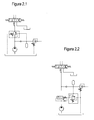
Figures 2.1, 2.2 : show the hydraulic diagrams of two application examples of the valves according to the prior art, -
Figures 3.1, 3.2, 3.3 : show the hydraulic symbols of the invention and an example of application, -
Figures 4.1, 4.2 : show the hydraulic symbols and the cross-sections of the two types of valves of the prior art, -
Figure 5.1 : shows the implementation of the invention with different highlighted details which make up the valve, -
Figures 5.2 - 5.5 : show the valve in the different positions which it takes during the switching. - With reference to
Figure 1.1 , it is shown a first application of the valve of the invention. - It is a load sensing hydraulic system dedicated to the management of a differential load of an accumulator. In such circuit, the valve is branched with respect to the main line supplied by the pump.
- With reference to
Figure 1.2 , it is shown a second application of the valve of the invention. - It is a low flow rate hydraulic system supplied by an accumulator loaded by a fixed-displacement pump. The valve in such circuit is branched with respect to the main line supplied by the pump and it discharges the flow rate of the same pump, when the accumulator is loaded.
- With reference to
Figure 1.3 , it is shown a third application of the valve of the invention. - It is a low flow rate hydraulic system having a fixed-displacement pump dedicated to the management of a differential load of an accumulator. In such circuit, the valve is in series to the pump.
- Particularly, with reference to
Figures 2.1, 2.2 , hydraulic diagrams of two examples using the valves according to the prior art are shown. - The first example of the prior art is shown in
Figure 2.1 . - The hydraulic diagram of an example of application of the four-way outer drainage valve is shown; said valve is characterized by a main stage, which, in the rest position, closes the oil passage between the
ports Figure 4.1 ). - When the pilot pressure, during the pressure increase, reaches the increasing adjustment pressure, the pilot stage operates by driving the main stage which opens the passage between the
ports - Instead, when the pressure, during the decreasing step, reaches the decreasing adjustment value, the pilot stage operates by closing the main stage, restoring the rest condition.
- Usually, such type of valve is used in circuits managing a differential load of an hydraulic accumulator.
- It is connected to a fixed-displacement pump and it is connected in series to the pump itself.
- Operatively, the valve determines a deliver pressure increase, in order to enable the loading of the accumulator, when the valve is in a closed rest position, in other words it is not piloted.
- Instead, the valve is opened, when the pressure in the accumulator is greater than the decreasing adjustment pressure.
- In such condition, the valve, also if opened, throttles the passage by forming a power loss. In order to reduce at the maximum such loss, it is necessary to have large oil passages.
- A main disadvantage of this kind of valve is due to the fact that for keeping switched the same, it is necessary to have a continuous passage of oil from the
port 1 to thedrainage port 4 and this causes a flow rate loss and consequently a power loss. - In addition, such type of valve is not adapted to work with load sensing circuits, both with a LS pump and a pressure compensator; for said circuits (whose application is shown in
Figure 1.1 ) it is necessary to act on the signal LS for managing the load of the accumulator and it is not necessary to have any valve in series to the pump. Particularly, it is necessary to connect the pressure main line to the line LS in order to have the greatest flow rate and pressure in order to load the accumulator. - When the accumulator is loaded, the valve must close again for interrupting the passage connecting the pump to its signal LS.
- It is necessary that the sequence valve should be normally opened.
- There is a second type of valve characterized by a double adjustment pressure.
- The second example of the prior art is shown in
Figure 2.2 which illustrates the hydraulic circuit of an example of application of the outer piloting three-way valve; (see alsoFigure 4.2 ). - Such valve substantially comprises a valve pilot stage of
Figure 4.1 (described before) and it is normally coupled to a logic element. Such approach enables to obtain high work flow rates in the system, by always draining the drainage oil through the described valve in order to keep opened the logic element. - A further disadvantage for both the described approaches, is due to the fact that the sizes of the oil passages, typical of the cited circuits, formed by a main element and a pilot stage, are not adapted to manage a low flow rate signal as required by this kind of circuit. In fact, the pilot systems are instable in presence of low working flow rates and have response time greater than the one of a direct operation approach.
-
Figure 3.1 illustrates the hydraulic complete symbol of the invention in a normally closed version, whileFigure3.2 illustrates the complete hydraulic symbol of the invention in a normally opened version. - Instead,
Figure 3.3 shows the hydraulic diagram of a typical application of the valve, in other words a load sensing circuit managing the differential load of an accumulator. -
Figure 5.1 instead illustrates a cross-section of the valve of the invention, in a normally opened version with highlighted different details of the same. -
Figure 5.2 - 5.5 illustrate the valve in the different positions which it takes during the switching. - The invention refers to a direct slide four-ways differential double adjustment valve having an outer pilot, normally opened or normally closed, wherein:
- during the pilot increasing pressure step, once it has been reached the increasing adjustment value, the valve operates by opening (if it is normally closed) or closing (if it is normally opened) the passage between the two ways dedicated to the oil passage, while
- during the pilot decreasing pressure step, once it has been reached the decreasing adjustment value, the valve returns to the starting arrangement.
- The value of the adjustment increasing pressure is always greater than the one of the adjustment decreasing pressure and the ratio between such values is determined by the valve differential.
- A cross-section of the valve, generally indicated at 20, in a normally opened version is shown in
Figure 5.1 , while the corresponding hydraulic diagram is shown inFigure 3.2 . - In both the figures,
number 1 indicates the piloting port of thevalve 20,number 2 indicates the flow rate passage inlet port,number 3 indicates the flow rate passage outlet port, andnumber 4 indicates the drainage port of the same, which must be connected to the drain. - By observing
Figure 5.1 , it is possible to list the main components making up thevalve 20 in the usually opened arrangement. - Particularly,
number 6 indicates the cartridge of the valve in which aslide 5 moves, having a pushing area A5. - Instead,
number 8 indicates the piston having a pushing area A8, moving inside thebushing 9. Thebushing 9 is coaxial with respect to the cartridge, so that to enable thepiston 8 and theslide 5 to axially move abutting one against the other in the inner gauged hole. -
Number 7 indicates the secondary spring having the function of keeping together the twocomponents -
Number 11 indicates resilient means, in the example a main spring, acting on the outer end of the piston 8 (that is opposed to the slide 5), used for generating a force opposing to the piloting pressure, in order to obtain the desired adjustment pressure of the valve, while 12 indicates the registering screw used for precharging thespring 11. -
Number 10 indicates the spring-holder, thecartridge 6 is coupled to it by a thread and a calking not shown in the figure. - In order to take the drainage signal of the
port 4 in the spring side chamber D, two millings FR are made on thecartridge 6 sides at the thread used for connecting thecartridge 6 to the spring-holder 10. - The switching of the
valve 20, to the normally opened arrangement, occurs when the connection between theports port 2 of thecartridge 6, by the corner S2 present on the slide 5 (see alsoFigure 5.3 ). - The double adjustment of the valve is ensured by the difference between the pushing area A5 of the
slide 5 and the pushing area A8 of thepiston 8. - Particularly, the
valve 20 differential, that is the ratio between the increasing adjustment and the decreasing adjustment, is given by the ratio between these two pushing areas. - By modifying such areas, it is possible to modify the differential of the same valve.
- In the following the valve exchange operation will be described with reference to the normally opened version shown in
Figure 5.1 . -
Figure 5.1 illustrates the valve in the rest arrangement, that is without a pressure on the pilotingport 1. - In such arrangement, it is enabled the oil passage between the
ports - Assuming the pressure at the
same port 1 increases to a value p1 such not to pilot the valve, the same value p1 through the hole F1 enters the chamber B, then passes in chamber C through the holes F3. Since the shoulder S3 is provided with a positive overlapping with respect to holes of thevalve ports 4, the chambers B and C are isolated from the drainage of the same. - In such condition, the
slide 5 is balanced because theport 1 and the chamber C are at the same pressure p1. Thepiston 8 is subjected to the pressure p1 present in the chamber C and to the drainage pressure present in chamber D. - A force formed by the product between the pressure p1 and the pushing area A8, opposed by the pre-load force of the
main spring 11, is formed on thepiston 8. - The
piston 8 does not move until the pressure p1 does not generate a force such to balance thespring 11 force, at the same time theslide 5 remains stopped due to thesecondary spring 7 action which keeps it integral to thepiston 8. - When p1 is greater than the preload of the
spring 11, thepiston 8 and theslide 5, thanks to thespring 7 action, move upwardly, by reducing theport 2 opening and by reducing the shoulder S3 overlapping towards the holes of thevalve 20port 4. - When the overlapping arrangement of such shoulder due to the pressure p1 is absent (see
Figure 5.2 ), it is reached the switching position of the valve and the pressure p1 equals the switching increasing pressure ofvalve 20. - A further slight increase of pressure p1 in fact determines the opening of the holes of the
port 4 by the shoulder S3 of theslide 5. - During this operation, the chamber B and consequently chamber C, through the holes F3 are connected to the
port 4, so the pressure in chamber C decreases to the drainage pressure. - The
piston 8 is now balanced (chambers C and D are both at the drainage pressure), while theslide 5 is at pressure p1 at theport 1 and at the drainage pressure in chamber C. - The force opposing the
main spring 11 increases because with the same pressure p1, the pushing area passes from the value A8 of the piston to the greater value A5 of the slide. - Therefore, the system equilibrium fails and the
slide 5 is moved to the stop with thepiston 8. - To summarize, the increasing pilot pressure value equals the preload force of the spring seen in the
Figure 5.2 arrangement, divided by the piston area A8; as soon as it is passed this position, it is lost the equilibrium condition on the slide so that it is quickly pushed to the stop. - It is to be noted that the exchange operation is generated when the
port 2 is still opened (seeFigure 5.2 ). - Instead, at the stop, this port is closed (see
Figure 5.5 ). - It is very important to note that both in the rest position and in the stop position, the piloting
port 1,port 2, andport 3 are isolated from the drainage port. Therefore, it is not necessary to have an oil passage for keeping piloted thevalve 20. - The
port 1 is connected to the drainage only during the switching from the position shown inFigure 5.2 to the one shown inFigure 5.4 . - It is to be noted that once it is passed the position in
Figure 5.2 , that is the starting switching positions, thevalve 20 does not find a next equilibrium position until it reaches the stop position (seeFigure 5.5 ), so that the exchange time is very low. - Therefore, the presence of the
drainage port 4 is provided for taking the pressure of the same drainage in chamber C in order to promote the described switching of the valve and to avoid the counter pressure in chamber D of the spring space. - The valve, having reached the stop position, remains in this position until the
port 1 pressure reaches the decreasing pressure value of thevalve 20. - Such pressure value, as it will be shown, equals the spring preload force seen in the
Figure 5.4 arrangement, divided by the slide area A8. - More specifically, during the decreasing pressure step at the
port 1 of the valve, there are not any changes until it is reached the arrangement shown inFigure 5.4 . In such condition, thevalve port 1 is still isolated (the overlapping is absent) both from chamber B and chamber C which are at the drainage pressure. - Therefore, the
slide 5 is pushed by the pressure p1 on the area A5 and is balanced by thespring 11 force. Since area A5 is greater than the piston area A8, the equilibrium pressure is less than the adjustment increasing pressure of thevalve 20. - As soon as the shoulder S1 opens the
port 1, the pressure in chambers B and C starts to reach again the value p1, so that the pushing area contrasting thespring 11 is again equal to A8, that is it is the area of thepiston 8. - The pressure level is less than the value of the increasing adjustment, so that, once again, the slide-piston assembly is not in equilibrium, because the
spring 11 force is greater than the pressure p1 value (it is equal to the decreasing adjustment pressure) multiplied by the area of the piston A8. - This fact determines that the
valve 20 is pushed in the rest position shown inFigure 5.1 . - Also in this case, the switching operation is generated when the
port 2 is still closed (seeFigure 5.4 ). Instead, at rest, this port is opened (seeFigure 5.1 ). The described switching operation of the normally openedvalve 20 is the same as the one of the normally closedvalve 20, the difference being that the passage between theports 2 is located at the opposed logic state in each arrangement of the valve (seeFigures 5.1 - 5.5 ). During the switching operation, there are other forces beside the forces of thespring 11 and pressure p1. Such forces are the flow forces generated near the openings or near the closure of the openings. - For reducing the effect, it is possible to introduce some flaps which are segments of the slide having an increased diameter.
-
Figure 5.1 illustrates the flap D used for reducing the effect of the flow forces at the opening of the port on theport 2 of thevalve 20. - The flow forces effect can also appear at the opening of the shoulders S1 and S3.
- Anyway, it is possible to position flaps also on the shoulders S1 and S3 in order to avoid such effects.
- A further factor occurring during the switching operation, is shown by the sizes of the holes F1 and F2 present on the
slide 5. - Such holes modify the speed at which the chambers B and C can modify their pressure level, particularly by passing from the drainage pressure to the one of the piloting
port 1. - By changing the size of such holes it is possible to act on the switching speed by promoting the increasing steady one of the pressure, rather than the steady decreasing one or vice versa.
- A further possible action enabling to modify such switching times consists of inserting a further dowel in position G in
Figure 5.1 , which for the sake of simplicity has been represented by a broken line square inside the conduit to chamber B. - By changing the size of holes F1, F2 and/or dowel G, enables to optimize the switching times in order to improve the system stability in which the valve is inserted.
- It is possible to substitute said two separated components, the
slide 5 and thepiston 8 for a single component. - The main advantage of maintaining separated the components is due to the fact that it is not necessary to have a coaxial thrust between the inner diameter of the
bushing 9 and thecartridge 6, theslide 5 and thepiston 8 must freely slide in these areas. - A further advantage is due to the fact that the grinding of a single component on two diameters is certainly more complex than the one on two separate components.
- The disadvantage of the approach shown in
Figure 5.1 is represented by the necessity of using thesecondary spring 7 which would be not necessary if thecomponents - A further constructive variant can be implemented by inserting drilled dowels inside the
slide 5 instead of the adjusted holes F1, F2 (adapted to communicate the inner chambers B and C with theports 1 and 4), for more easily adapting thevalve 20 to the different needs of the system in which the valve is located, without modifying the shape of the slide.
Claims (10)
- Externally piloted double adjustment differential four-ways direct slide (5) valve (20), normally opened or normally closed, of the type comprising: a piloting port (1), inlet, outlet and flow rate passage ports (2, 3), a drainage port (4), connected to a drain; said ports (1, 2, 3, 4) being made in a cartridge (6) of valve (20) in which the slide (5) is freely movable inside a corresponding hole having an area (A5); a piston (8), having a pushing area (A8), in turn axially slidable inside a bushing (9) coaxial with said cartridge (6); wherein the valve (20) has a rest position, in which the connection between the ports (2) and (3) is opened, when the valve is normally opened or closed when the valve is normally closed, and a stop position, in which the connection between the ports (2) and (3) is closed in case the valve is normally opened or opened in case the valve is normally closed; characterized by the fact that the resilient means (11) act against said piston (8) on the side opposite to the slide (5), whose preload determines the valve (20) adjustment; said valve (20) defining two limit positions, wherein also in the stop position the pilot port (1) and ports (2) and (3) are isolated from the drainage port (4).
- Valve (20) according to claim 1, characterized by the fact the port (1) is connected to the drainage (4) only during the switching step which starts:a. during the increasing pilot pressure step when the pilot pressure at the port (1) reaches the increasing adjustment pressure value, equal to the value of the spring (11) preload force divided by the area (A8) of the piston (8),b. during the pilot decreasing pressure step, when the pressure at the piloting port (1) reaches the decreasing adjustment pressure value, equal to the spring (11) preload force divided by the area (A5) of the slide (5), once it has been passed the switching starting position, said valve (20) does not find a successive equilibrium position until it reaches, during the increasing pressure step, the stop position, during the decreasing pressure step, the rest position; the effective exchange position, that is when it is opened or closed the connection between the ports (2) and (3), it is always inside this transition step.
- Valve (20) according to claim 1 and 2, characterized by the fact the adjustment increasing pressure value is always greater than the one of the decreasing adjustment pressure and the ratio between such values equals the valve differential, which can be computed also as the ratio between the slide (5) pushing area (A5) and the piston (8) pushing area (A8).
- Valve (20) according to claim 1 and 2, characterized by the fact the switching operation, during the increasing steady state of the pressure, rather than in the decreasing steady state, is adjusted, with reference to the operation speed, by the size of holes (F1) and (F2), on the slide (5), adapted to communicate the inner chambers (B) and (C) with the ports (1) and (4).
- Valve (20) according to claim 4, characterized by the fact it comprises a further dowel (G) inside the chamber (B) conduit.
- Valve (20) according to claim 4 or 5, characterized by the fact it comprises drilled dowels inside the slide (5) instead of the adjusted holes (F1, F2), for more easily adapting the valve (20) to the different needs of a plant in which it is located the valve without modifying the shape of the slide (5).
- Valve (20) according to claim 1, characterized by the fact the slide (5) and piston (8) are separate elements and a secondary spring (7) keeps integral said two components (5) and (8) during the operation.
- Valve (20) according to claim 1, characterized by the fact the slide (5) and piston (8) are combined and integral in a single component.
- Valve (20) according to claim 1, characterized by the fact it further comprises flaps for limiting the flow forces generating, during the exchange operation, near the opening of the ports or near the closing of the same.
- Valve (20) according to claim 9, characterized by the fact said flaps are segments having an increased diameter on the slide (5).
Applications Claiming Priority (1)
| Application Number | Priority Date | Filing Date | Title |
|---|---|---|---|
| ITPR2010A000026A IT1399545B1 (en) | 2010-04-13 | 2010-04-13 | HYDRAULIC VALVE OF DIFFERENTIAL SEQUENCE. |
Publications (2)
| Publication Number | Publication Date |
|---|---|
| EP2378135A1 EP2378135A1 (en) | 2011-10-19 |
| EP2378135B1 true EP2378135B1 (en) | 2012-12-19 |
Family
ID=43128200
Family Applications (1)
| Application Number | Title | Priority Date | Filing Date |
|---|---|---|---|
| EP20110162339 Not-in-force EP2378135B1 (en) | 2010-04-13 | 2011-04-13 | Differential sequence hydraulic valve |
Country Status (2)
| Country | Link |
|---|---|
| EP (1) | EP2378135B1 (en) |
| IT (1) | IT1399545B1 (en) |
Cited By (2)
| Publication number | Priority date | Publication date | Assignee | Title |
|---|---|---|---|---|
| DE102014226153A1 (en) * | 2014-12-17 | 2016-06-23 | Zf Friedrichshafen Ag | Device for unlocking pressure-less closed pressure-locked hydraulically actuated switching elements of a transmission of a motor vehicle |
| CN108223475A (en) * | 2018-02-05 | 2018-06-29 | 陈艳艳 | A kind of compact one way sequence valve |
Families Citing this family (3)
| Publication number | Priority date | Publication date | Assignee | Title |
|---|---|---|---|---|
| FI124594B (en) | 2013-04-03 | 2014-10-31 | Wärtsilä Finland Oy | Directional valve for a fluid engineering system |
| CN112460079A (en) * | 2020-12-10 | 2021-03-09 | 山东泰丰智能控制股份有限公司 | Energy accumulator module for increasing response speed |
| CN116181745B (en) * | 2023-03-07 | 2026-05-05 | 山河智能特种装备有限公司 | A hydraulic system with oil leakage protection, engineering machinery and oil leakage protection method |
Family Cites Families (3)
| Publication number | Priority date | Publication date | Assignee | Title |
|---|---|---|---|---|
| DE3605980A1 (en) * | 1985-03-05 | 1986-10-16 | Barmag Barmer Maschinenfabrik Ag, 5630 Remscheid | Proportional valve with pressure-difference balance |
| DE10104101A1 (en) * | 2000-02-10 | 2001-08-16 | Luk Lamellen & Kupplungsbau | Pressure control valve e.g. for start-up coupling of motor vehicle, has working chamber connected via throttle connection to the supply pressure point |
| KR100780897B1 (en) * | 2006-09-28 | 2007-11-30 | 볼보 컨스트럭션 이키프먼트 홀딩 스웨덴 에이비 | Heavy Duty Pressure Controls |
-
2010
- 2010-04-13 IT ITPR2010A000026A patent/IT1399545B1/en active
-
2011
- 2011-04-13 EP EP20110162339 patent/EP2378135B1/en not_active Not-in-force
Cited By (2)
| Publication number | Priority date | Publication date | Assignee | Title |
|---|---|---|---|---|
| DE102014226153A1 (en) * | 2014-12-17 | 2016-06-23 | Zf Friedrichshafen Ag | Device for unlocking pressure-less closed pressure-locked hydraulically actuated switching elements of a transmission of a motor vehicle |
| CN108223475A (en) * | 2018-02-05 | 2018-06-29 | 陈艳艳 | A kind of compact one way sequence valve |
Also Published As
| Publication number | Publication date |
|---|---|
| EP2378135A1 (en) | 2011-10-19 |
| IT1399545B1 (en) | 2013-04-19 |
| ITPR20100026A1 (en) | 2011-10-14 |
Similar Documents
| Publication | Publication Date | Title |
|---|---|---|
| KR102156446B1 (en) | Hydraulic system of Construction machinery | |
| EP2378135A1 (en) | Differential sequence hydraulic valve | |
| US9550521B2 (en) | Hydraulic steering arrangement | |
| US9874884B2 (en) | Valve block having a valve assembly | |
| US8479769B2 (en) | Hydraulic valve device | |
| US10024342B2 (en) | Load sensing control circuit | |
| CN105697764B (en) | The hydraulic control unit of form locking switching element for speed changer | |
| JPH102436A (en) | Cartridge valve | |
| US20190203743A1 (en) | Hydraulic no-back device | |
| CN104132016A (en) | Three-way flow valve, load sensing multi-way valve, hydraulic system and construction machinery | |
| EP2330303B1 (en) | Device for controlling a pilot pressure signal | |
| CN108662222A (en) | A kind of pilot-operated type threeway proportional pressure-reducing valve | |
| CN103671058B (en) | Adjustment equipment and hydrostatic pump for hydrostatic pump | |
| US6095177A (en) | Precontrolled 3-way pressure control valve | |
| EP2568182B1 (en) | Dual positive displacement pump pressure regulating control | |
| US20180163889A1 (en) | Valve, in particular proportional pressure regulating valve | |
| CN105247224B (en) | Hydraulic valve arrangement | |
| US7603940B2 (en) | Hydraulic controller arrangement | |
| JP5708618B2 (en) | Hydraulic control valve | |
| US20120006427A1 (en) | Hydraulic Valve Device | |
| US20070272889A1 (en) | Valve | |
| CN204082831U (en) | Accumulator charging valve assembly | |
| CN104295781A (en) | Safety throttle valve | |
| US9695843B2 (en) | Hydraulic load-sensing control arrangement | |
| CN108302222B (en) | Valve assembly for double circuit - Summierung |
Legal Events
| Date | Code | Title | Description |
|---|---|---|---|
| AK | Designated contracting states |
Kind code of ref document: A1 Designated state(s): AL AT BE BG CH CY CZ DE DK EE ES FI FR GB GR HR HU IE IS IT LI LT LU LV MC MK MT NL NO PL PT RO RS SE SI SK SM TR |
|
| AX | Request for extension of the european patent |
Extension state: BA ME |
|
| PUAI | Public reference made under article 153(3) epc to a published international application that has entered the european phase |
Free format text: ORIGINAL CODE: 0009012 |
|
| 17P | Request for examination filed |
Effective date: 20120417 |
|
| GRAP | Despatch of communication of intention to grant a patent |
Free format text: ORIGINAL CODE: EPIDOSNIGR1 |
|
| GRAS | Grant fee paid |
Free format text: ORIGINAL CODE: EPIDOSNIGR3 |
|
| GRAA | (expected) grant |
Free format text: ORIGINAL CODE: 0009210 |
|
| AK | Designated contracting states |
Kind code of ref document: B1 Designated state(s): AL AT BE BG CH CY CZ DE DK EE ES FI FR GB GR HR HU IE IS IT LI LT LU LV MC MK MT NL NO PL PT RO RS SE SI SK SM TR |
|
| REG | Reference to a national code |
Ref country code: GB Ref legal event code: FG4D |
|
| REG | Reference to a national code |
Ref country code: CH Ref legal event code: EP |
|
| REG | Reference to a national code |
Ref country code: AT Ref legal event code: REF Ref document number: 589572 Country of ref document: AT Kind code of ref document: T Effective date: 20130115 |
|
| REG | Reference to a national code |
Ref country code: DE Ref legal event code: R096 Ref document number: 602011000614 Country of ref document: DE Effective date: 20130228 |
|
| PG25 | Lapsed in a contracting state [announced via postgrant information from national office to epo] |
Ref country code: NO Free format text: LAPSE BECAUSE OF FAILURE TO SUBMIT A TRANSLATION OF THE DESCRIPTION OR TO PAY THE FEE WITHIN THE PRESCRIBED TIME-LIMIT Effective date: 20130319 Ref country code: ES Free format text: LAPSE BECAUSE OF FAILURE TO SUBMIT A TRANSLATION OF THE DESCRIPTION OR TO PAY THE FEE WITHIN THE PRESCRIBED TIME-LIMIT Effective date: 20130330 Ref country code: SE Free format text: LAPSE BECAUSE OF FAILURE TO SUBMIT A TRANSLATION OF THE DESCRIPTION OR TO PAY THE FEE WITHIN THE PRESCRIBED TIME-LIMIT Effective date: 20121219 Ref country code: LT Free format text: LAPSE BECAUSE OF FAILURE TO SUBMIT A TRANSLATION OF THE DESCRIPTION OR TO PAY THE FEE WITHIN THE PRESCRIBED TIME-LIMIT Effective date: 20121219 Ref country code: HR Free format text: LAPSE BECAUSE OF FAILURE TO SUBMIT A TRANSLATION OF THE DESCRIPTION OR TO PAY THE FEE WITHIN THE PRESCRIBED TIME-LIMIT Effective date: 20121219 Ref country code: FI Free format text: LAPSE BECAUSE OF FAILURE TO SUBMIT A TRANSLATION OF THE DESCRIPTION OR TO PAY THE FEE WITHIN THE PRESCRIBED TIME-LIMIT Effective date: 20121219 |
|
| REG | Reference to a national code |
Ref country code: NL Ref legal event code: VDEP Effective date: 20121219 Ref country code: AT Ref legal event code: MK05 Ref document number: 589572 Country of ref document: AT Kind code of ref document: T Effective date: 20121219 |
|
| REG | Reference to a national code |
Ref country code: LT Ref legal event code: MG4D |
|
| PG25 | Lapsed in a contracting state [announced via postgrant information from national office to epo] |
Ref country code: GR Free format text: LAPSE BECAUSE OF FAILURE TO SUBMIT A TRANSLATION OF THE DESCRIPTION OR TO PAY THE FEE WITHIN THE PRESCRIBED TIME-LIMIT Effective date: 20130320 Ref country code: SI Free format text: LAPSE BECAUSE OF FAILURE TO SUBMIT A TRANSLATION OF THE DESCRIPTION OR TO PAY THE FEE WITHIN THE PRESCRIBED TIME-LIMIT Effective date: 20121219 Ref country code: LV Free format text: LAPSE BECAUSE OF FAILURE TO SUBMIT A TRANSLATION OF THE DESCRIPTION OR TO PAY THE FEE WITHIN THE PRESCRIBED TIME-LIMIT Effective date: 20121219 |
|
| PG25 | Lapsed in a contracting state [announced via postgrant information from national office to epo] |
Ref country code: AT Free format text: LAPSE BECAUSE OF FAILURE TO SUBMIT A TRANSLATION OF THE DESCRIPTION OR TO PAY THE FEE WITHIN THE PRESCRIBED TIME-LIMIT Effective date: 20121219 Ref country code: SK Free format text: LAPSE BECAUSE OF FAILURE TO SUBMIT A TRANSLATION OF THE DESCRIPTION OR TO PAY THE FEE WITHIN THE PRESCRIBED TIME-LIMIT Effective date: 20121219 Ref country code: IS Free format text: LAPSE BECAUSE OF FAILURE TO SUBMIT A TRANSLATION OF THE DESCRIPTION OR TO PAY THE FEE WITHIN THE PRESCRIBED TIME-LIMIT Effective date: 20130419 Ref country code: CZ Free format text: LAPSE BECAUSE OF FAILURE TO SUBMIT A TRANSLATION OF THE DESCRIPTION OR TO PAY THE FEE WITHIN THE PRESCRIBED TIME-LIMIT Effective date: 20121219 Ref country code: BE Free format text: LAPSE BECAUSE OF FAILURE TO SUBMIT A TRANSLATION OF THE DESCRIPTION OR TO PAY THE FEE WITHIN THE PRESCRIBED TIME-LIMIT Effective date: 20121219 Ref country code: EE Free format text: LAPSE BECAUSE OF FAILURE TO SUBMIT A TRANSLATION OF THE DESCRIPTION OR TO PAY THE FEE WITHIN THE PRESCRIBED TIME-LIMIT Effective date: 20121219 Ref country code: RS Free format text: LAPSE BECAUSE OF FAILURE TO SUBMIT A TRANSLATION OF THE DESCRIPTION OR TO PAY THE FEE WITHIN THE PRESCRIBED TIME-LIMIT Effective date: 20121219 Ref country code: BG Free format text: LAPSE BECAUSE OF FAILURE TO SUBMIT A TRANSLATION OF THE DESCRIPTION OR TO PAY THE FEE WITHIN THE PRESCRIBED TIME-LIMIT Effective date: 20130319 |
|
| PG25 | Lapsed in a contracting state [announced via postgrant information from national office to epo] |
Ref country code: RO Free format text: LAPSE BECAUSE OF FAILURE TO SUBMIT A TRANSLATION OF THE DESCRIPTION OR TO PAY THE FEE WITHIN THE PRESCRIBED TIME-LIMIT Effective date: 20121219 Ref country code: PL Free format text: LAPSE BECAUSE OF FAILURE TO SUBMIT A TRANSLATION OF THE DESCRIPTION OR TO PAY THE FEE WITHIN THE PRESCRIBED TIME-LIMIT Effective date: 20121219 Ref country code: PT Free format text: LAPSE BECAUSE OF FAILURE TO SUBMIT A TRANSLATION OF THE DESCRIPTION OR TO PAY THE FEE WITHIN THE PRESCRIBED TIME-LIMIT Effective date: 20130419 Ref country code: NL Free format text: LAPSE BECAUSE OF FAILURE TO SUBMIT A TRANSLATION OF THE DESCRIPTION OR TO PAY THE FEE WITHIN THE PRESCRIBED TIME-LIMIT Effective date: 20121219 |
|
| PLBE | No opposition filed within time limit |
Free format text: ORIGINAL CODE: 0009261 |
|
| STAA | Information on the status of an ep patent application or granted ep patent |
Free format text: STATUS: NO OPPOSITION FILED WITHIN TIME LIMIT |
|
| PG25 | Lapsed in a contracting state [announced via postgrant information from national office to epo] |
Ref country code: DK Free format text: LAPSE BECAUSE OF FAILURE TO SUBMIT A TRANSLATION OF THE DESCRIPTION OR TO PAY THE FEE WITHIN THE PRESCRIBED TIME-LIMIT Effective date: 20121219 |
|
| 26N | No opposition filed |
Effective date: 20130920 |
|
| PG25 | Lapsed in a contracting state [announced via postgrant information from national office to epo] |
Ref country code: CY Free format text: LAPSE BECAUSE OF FAILURE TO SUBMIT A TRANSLATION OF THE DESCRIPTION OR TO PAY THE FEE WITHIN THE PRESCRIBED TIME-LIMIT Effective date: 20121219 Ref country code: MC Free format text: LAPSE BECAUSE OF FAILURE TO SUBMIT A TRANSLATION OF THE DESCRIPTION OR TO PAY THE FEE WITHIN THE PRESCRIBED TIME-LIMIT Effective date: 20121219 |
|
| REG | Reference to a national code |
Ref country code: DE Ref legal event code: R097 Ref document number: 602011000614 Country of ref document: DE Effective date: 20130920 |
|
| REG | Reference to a national code |
Ref country code: IE Ref legal event code: MM4A |
|
| PG25 | Lapsed in a contracting state [announced via postgrant information from national office to epo] |
Ref country code: IE Free format text: LAPSE BECAUSE OF NON-PAYMENT OF DUE FEES Effective date: 20130413 |
|
| PGFP | Annual fee paid to national office [announced via postgrant information from national office to epo] |
Ref country code: DE Payment date: 20140418 Year of fee payment: 4 Ref country code: FR Payment date: 20140422 Year of fee payment: 4 Ref country code: IT Payment date: 20140430 Year of fee payment: 4 |
|
| REG | Reference to a national code |
Ref country code: CH Ref legal event code: PL |
|
| PG25 | Lapsed in a contracting state [announced via postgrant information from national office to epo] |
Ref country code: CH Free format text: LAPSE BECAUSE OF NON-PAYMENT OF DUE FEES Effective date: 20140430 Ref country code: LI Free format text: LAPSE BECAUSE OF NON-PAYMENT OF DUE FEES Effective date: 20140430 |
|
| PG25 | Lapsed in a contracting state [announced via postgrant information from national office to epo] |
Ref country code: MT Free format text: LAPSE BECAUSE OF FAILURE TO SUBMIT A TRANSLATION OF THE DESCRIPTION OR TO PAY THE FEE WITHIN THE PRESCRIBED TIME-LIMIT Effective date: 20121219 |
|
| PG25 | Lapsed in a contracting state [announced via postgrant information from national office to epo] |
Ref country code: SM Free format text: LAPSE BECAUSE OF FAILURE TO SUBMIT A TRANSLATION OF THE DESCRIPTION OR TO PAY THE FEE WITHIN THE PRESCRIBED TIME-LIMIT Effective date: 20121219 |
|
| PG25 | Lapsed in a contracting state [announced via postgrant information from national office to epo] |
Ref country code: TR Free format text: LAPSE BECAUSE OF FAILURE TO SUBMIT A TRANSLATION OF THE DESCRIPTION OR TO PAY THE FEE WITHIN THE PRESCRIBED TIME-LIMIT Effective date: 20121219 |
|
| PG25 | Lapsed in a contracting state [announced via postgrant information from national office to epo] |
Ref country code: LU Free format text: LAPSE BECAUSE OF NON-PAYMENT OF DUE FEES Effective date: 20130413 Ref country code: HU Free format text: LAPSE BECAUSE OF FAILURE TO SUBMIT A TRANSLATION OF THE DESCRIPTION OR TO PAY THE FEE WITHIN THE PRESCRIBED TIME-LIMIT; INVALID AB INITIO Effective date: 20110413 Ref country code: MK Free format text: LAPSE BECAUSE OF FAILURE TO SUBMIT A TRANSLATION OF THE DESCRIPTION OR TO PAY THE FEE WITHIN THE PRESCRIBED TIME-LIMIT Effective date: 20121219 |
|
| REG | Reference to a national code |
Ref country code: DE Ref legal event code: R119 Ref document number: 602011000614 Country of ref document: DE |
|
| GBPC | Gb: european patent ceased through non-payment of renewal fee |
Effective date: 20150413 |
|
| PG25 | Lapsed in a contracting state [announced via postgrant information from national office to epo] |
Ref country code: DE Free format text: LAPSE BECAUSE OF NON-PAYMENT OF DUE FEES Effective date: 20151103 Ref country code: GB Free format text: LAPSE BECAUSE OF NON-PAYMENT OF DUE FEES Effective date: 20150413 Ref country code: IT Free format text: LAPSE BECAUSE OF NON-PAYMENT OF DUE FEES Effective date: 20150413 |
|
| REG | Reference to a national code |
Ref country code: FR Ref legal event code: ST Effective date: 20151231 |
|
| PG25 | Lapsed in a contracting state [announced via postgrant information from national office to epo] |
Ref country code: FR Free format text: LAPSE BECAUSE OF NON-PAYMENT OF DUE FEES Effective date: 20150430 |
|
| PG25 | Lapsed in a contracting state [announced via postgrant information from national office to epo] |
Ref country code: AL Free format text: LAPSE BECAUSE OF FAILURE TO SUBMIT A TRANSLATION OF THE DESCRIPTION OR TO PAY THE FEE WITHIN THE PRESCRIBED TIME-LIMIT Effective date: 20121219 |