EP2377495A1 - Spinal implant - Google Patents
Spinal implant Download PDFInfo
- Publication number
- EP2377495A1 EP2377495A1 EP20100305406 EP10305406A EP2377495A1 EP 2377495 A1 EP2377495 A1 EP 2377495A1 EP 20100305406 EP20100305406 EP 20100305406 EP 10305406 A EP10305406 A EP 10305406A EP 2377495 A1 EP2377495 A1 EP 2377495A1
- Authority
- EP
- European Patent Office
- Prior art keywords
- component
- core
- implant
- tether
- core component
- Prior art date
- Legal status (The legal status is an assumption and is not a legal conclusion. Google has not performed a legal analysis and makes no representation as to the accuracy of the status listed.)
- Withdrawn
Links
Images




Classifications
-
- A—HUMAN NECESSITIES
- A61—MEDICAL OR VETERINARY SCIENCE; HYGIENE
- A61F—FILTERS IMPLANTABLE INTO BLOOD VESSELS; PROSTHESES; DEVICES PROVIDING PATENCY TO, OR PREVENTING COLLAPSING OF, TUBULAR STRUCTURES OF THE BODY, e.g. STENTS; ORTHOPAEDIC, NURSING OR CONTRACEPTIVE DEVICES; FOMENTATION; TREATMENT OR PROTECTION OF EYES OR EARS; BANDAGES, DRESSINGS OR ABSORBENT PADS; FIRST-AID KITS
- A61F2/00—Filters implantable into blood vessels; Prostheses, i.e. artificial substitutes or replacements for parts of the body; Appliances for connecting them with the body; Devices providing patency to, or preventing collapsing of, tubular structures of the body, e.g. stents
- A61F2/02—Prostheses implantable into the body
- A61F2/30—Joints
- A61F2/44—Joints for the spine, e.g. vertebrae or spinal discs
- A61F2/442—Intervertebral or spinal discs, e.g. resilient
- A61F2/4425—Intervertebral or spinal discs, e.g. resilient made of articulated components
-
- A—HUMAN NECESSITIES
- A61—MEDICAL OR VETERINARY SCIENCE; HYGIENE
- A61F—FILTERS IMPLANTABLE INTO BLOOD VESSELS; PROSTHESES; DEVICES PROVIDING PATENCY TO, OR PREVENTING COLLAPSING OF, TUBULAR STRUCTURES OF THE BODY, e.g. STENTS; ORTHOPAEDIC, NURSING OR CONTRACEPTIVE DEVICES; FOMENTATION; TREATMENT OR PROTECTION OF EYES OR EARS; BANDAGES, DRESSINGS OR ABSORBENT PADS; FIRST-AID KITS
- A61F2/00—Filters implantable into blood vessels; Prostheses, i.e. artificial substitutes or replacements for parts of the body; Appliances for connecting them with the body; Devices providing patency to, or preventing collapsing of, tubular structures of the body, e.g. stents
- A61F2/02—Prostheses implantable into the body
- A61F2/30—Joints
- A61F2/44—Joints for the spine, e.g. vertebrae or spinal discs
- A61F2/4455—Joints for the spine, e.g. vertebrae or spinal discs for the fusion of spinal bodies, e.g. intervertebral fusion of adjacent spinal bodies, e.g. fusion cages
-
- A—HUMAN NECESSITIES
- A61—MEDICAL OR VETERINARY SCIENCE; HYGIENE
- A61F—FILTERS IMPLANTABLE INTO BLOOD VESSELS; PROSTHESES; DEVICES PROVIDING PATENCY TO, OR PREVENTING COLLAPSING OF, TUBULAR STRUCTURES OF THE BODY, e.g. STENTS; ORTHOPAEDIC, NURSING OR CONTRACEPTIVE DEVICES; FOMENTATION; TREATMENT OR PROTECTION OF EYES OR EARS; BANDAGES, DRESSINGS OR ABSORBENT PADS; FIRST-AID KITS
- A61F2/00—Filters implantable into blood vessels; Prostheses, i.e. artificial substitutes or replacements for parts of the body; Appliances for connecting them with the body; Devices providing patency to, or preventing collapsing of, tubular structures of the body, e.g. stents
- A61F2/02—Prostheses implantable into the body
- A61F2/30—Joints
- A61F2002/30001—Additional features of subject-matter classified in A61F2/28, A61F2/30 and subgroups thereof
- A61F2002/30003—Material related properties of the prosthesis or of a coating on the prosthesis
- A61F2002/30004—Material related properties of the prosthesis or of a coating on the prosthesis the prosthesis being made from materials having different values of a given property at different locations within the same prosthesis
- A61F2002/30016—Material related properties of the prosthesis or of a coating on the prosthesis the prosthesis being made from materials having different values of a given property at different locations within the same prosthesis differing in hardness, e.g. Vickers, Shore, Brinell
-
- A—HUMAN NECESSITIES
- A61—MEDICAL OR VETERINARY SCIENCE; HYGIENE
- A61F—FILTERS IMPLANTABLE INTO BLOOD VESSELS; PROSTHESES; DEVICES PROVIDING PATENCY TO, OR PREVENTING COLLAPSING OF, TUBULAR STRUCTURES OF THE BODY, e.g. STENTS; ORTHOPAEDIC, NURSING OR CONTRACEPTIVE DEVICES; FOMENTATION; TREATMENT OR PROTECTION OF EYES OR EARS; BANDAGES, DRESSINGS OR ABSORBENT PADS; FIRST-AID KITS
- A61F2/00—Filters implantable into blood vessels; Prostheses, i.e. artificial substitutes or replacements for parts of the body; Appliances for connecting them with the body; Devices providing patency to, or preventing collapsing of, tubular structures of the body, e.g. stents
- A61F2/02—Prostheses implantable into the body
- A61F2/30—Joints
- A61F2002/30001—Additional features of subject-matter classified in A61F2/28, A61F2/30 and subgroups thereof
- A61F2002/30108—Shapes
- A61F2002/30199—Three-dimensional shapes
- A61F2002/30224—Three-dimensional shapes cylindrical
- A61F2002/30225—Flat cylinders, i.e. discs
-
- A—HUMAN NECESSITIES
- A61—MEDICAL OR VETERINARY SCIENCE; HYGIENE
- A61F—FILTERS IMPLANTABLE INTO BLOOD VESSELS; PROSTHESES; DEVICES PROVIDING PATENCY TO, OR PREVENTING COLLAPSING OF, TUBULAR STRUCTURES OF THE BODY, e.g. STENTS; ORTHOPAEDIC, NURSING OR CONTRACEPTIVE DEVICES; FOMENTATION; TREATMENT OR PROTECTION OF EYES OR EARS; BANDAGES, DRESSINGS OR ABSORBENT PADS; FIRST-AID KITS
- A61F2/00—Filters implantable into blood vessels; Prostheses, i.e. artificial substitutes or replacements for parts of the body; Appliances for connecting them with the body; Devices providing patency to, or preventing collapsing of, tubular structures of the body, e.g. stents
- A61F2/02—Prostheses implantable into the body
- A61F2/30—Joints
- A61F2002/30001—Additional features of subject-matter classified in A61F2/28, A61F2/30 and subgroups thereof
- A61F2002/30108—Shapes
- A61F2002/30199—Three-dimensional shapes
- A61F2002/30224—Three-dimensional shapes cylindrical
- A61F2002/30235—Three-dimensional shapes cylindrical tubular, e.g. sleeves
-
- A—HUMAN NECESSITIES
- A61—MEDICAL OR VETERINARY SCIENCE; HYGIENE
- A61F—FILTERS IMPLANTABLE INTO BLOOD VESSELS; PROSTHESES; DEVICES PROVIDING PATENCY TO, OR PREVENTING COLLAPSING OF, TUBULAR STRUCTURES OF THE BODY, e.g. STENTS; ORTHOPAEDIC, NURSING OR CONTRACEPTIVE DEVICES; FOMENTATION; TREATMENT OR PROTECTION OF EYES OR EARS; BANDAGES, DRESSINGS OR ABSORBENT PADS; FIRST-AID KITS
- A61F2/00—Filters implantable into blood vessels; Prostheses, i.e. artificial substitutes or replacements for parts of the body; Appliances for connecting them with the body; Devices providing patency to, or preventing collapsing of, tubular structures of the body, e.g. stents
- A61F2/02—Prostheses implantable into the body
- A61F2/30—Joints
- A61F2002/30001—Additional features of subject-matter classified in A61F2/28, A61F2/30 and subgroups thereof
- A61F2002/30316—The prosthesis having different structural features at different locations within the same prosthesis; Connections between prosthetic parts; Special structural features of bone or joint prostheses not otherwise provided for
- A61F2002/30329—Connections or couplings between prosthetic parts, e.g. between modular parts; Connecting elements
- A61F2002/30462—Connections or couplings between prosthetic parts, e.g. between modular parts; Connecting elements retained or tied with a rope, string, thread, wire or cable
-
- A—HUMAN NECESSITIES
- A61—MEDICAL OR VETERINARY SCIENCE; HYGIENE
- A61F—FILTERS IMPLANTABLE INTO BLOOD VESSELS; PROSTHESES; DEVICES PROVIDING PATENCY TO, OR PREVENTING COLLAPSING OF, TUBULAR STRUCTURES OF THE BODY, e.g. STENTS; ORTHOPAEDIC, NURSING OR CONTRACEPTIVE DEVICES; FOMENTATION; TREATMENT OR PROTECTION OF EYES OR EARS; BANDAGES, DRESSINGS OR ABSORBENT PADS; FIRST-AID KITS
- A61F2/00—Filters implantable into blood vessels; Prostheses, i.e. artificial substitutes or replacements for parts of the body; Appliances for connecting them with the body; Devices providing patency to, or preventing collapsing of, tubular structures of the body, e.g. stents
- A61F2/02—Prostheses implantable into the body
- A61F2/30—Joints
- A61F2002/30001—Additional features of subject-matter classified in A61F2/28, A61F2/30 and subgroups thereof
- A61F2002/30316—The prosthesis having different structural features at different locations within the same prosthesis; Connections between prosthetic parts; Special structural features of bone or joint prostheses not otherwise provided for
- A61F2002/30329—Connections or couplings between prosthetic parts, e.g. between modular parts; Connecting elements
- A61F2002/30476—Connections or couplings between prosthetic parts, e.g. between modular parts; Connecting elements locked by an additional locking mechanism
- A61F2002/30484—Mechanically expandable devices located on the first prosthetic part for locking into or onto the second prosthetic part
-
- A—HUMAN NECESSITIES
- A61—MEDICAL OR VETERINARY SCIENCE; HYGIENE
- A61F—FILTERS IMPLANTABLE INTO BLOOD VESSELS; PROSTHESES; DEVICES PROVIDING PATENCY TO, OR PREVENTING COLLAPSING OF, TUBULAR STRUCTURES OF THE BODY, e.g. STENTS; ORTHOPAEDIC, NURSING OR CONTRACEPTIVE DEVICES; FOMENTATION; TREATMENT OR PROTECTION OF EYES OR EARS; BANDAGES, DRESSINGS OR ABSORBENT PADS; FIRST-AID KITS
- A61F2/00—Filters implantable into blood vessels; Prostheses, i.e. artificial substitutes or replacements for parts of the body; Appliances for connecting them with the body; Devices providing patency to, or preventing collapsing of, tubular structures of the body, e.g. stents
- A61F2/02—Prostheses implantable into the body
- A61F2/30—Joints
- A61F2002/30001—Additional features of subject-matter classified in A61F2/28, A61F2/30 and subgroups thereof
- A61F2002/30316—The prosthesis having different structural features at different locations within the same prosthesis; Connections between prosthetic parts; Special structural features of bone or joint prostheses not otherwise provided for
- A61F2002/30329—Connections or couplings between prosthetic parts, e.g. between modular parts; Connecting elements
- A61F2002/30476—Connections or couplings between prosthetic parts, e.g. between modular parts; Connecting elements locked by an additional locking mechanism
- A61F2002/30495—Connections or couplings between prosthetic parts, e.g. between modular parts; Connecting elements locked by an additional locking mechanism using a locking ring
-
- A—HUMAN NECESSITIES
- A61—MEDICAL OR VETERINARY SCIENCE; HYGIENE
- A61F—FILTERS IMPLANTABLE INTO BLOOD VESSELS; PROSTHESES; DEVICES PROVIDING PATENCY TO, OR PREVENTING COLLAPSING OF, TUBULAR STRUCTURES OF THE BODY, e.g. STENTS; ORTHOPAEDIC, NURSING OR CONTRACEPTIVE DEVICES; FOMENTATION; TREATMENT OR PROTECTION OF EYES OR EARS; BANDAGES, DRESSINGS OR ABSORBENT PADS; FIRST-AID KITS
- A61F2/00—Filters implantable into blood vessels; Prostheses, i.e. artificial substitutes or replacements for parts of the body; Appliances for connecting them with the body; Devices providing patency to, or preventing collapsing of, tubular structures of the body, e.g. stents
- A61F2/02—Prostheses implantable into the body
- A61F2/30—Joints
- A61F2002/30001—Additional features of subject-matter classified in A61F2/28, A61F2/30 and subgroups thereof
- A61F2002/30316—The prosthesis having different structural features at different locations within the same prosthesis; Connections between prosthetic parts; Special structural features of bone or joint prostheses not otherwise provided for
- A61F2002/30535—Special structural features of bone or joint prostheses not otherwise provided for
- A61F2002/30594—Special structural features of bone or joint prostheses not otherwise provided for slotted, e.g. radial or meridian slot ending in a polar aperture, non-polar slots, horizontal or arcuate slots
-
- A—HUMAN NECESSITIES
- A61—MEDICAL OR VETERINARY SCIENCE; HYGIENE
- A61F—FILTERS IMPLANTABLE INTO BLOOD VESSELS; PROSTHESES; DEVICES PROVIDING PATENCY TO, OR PREVENTING COLLAPSING OF, TUBULAR STRUCTURES OF THE BODY, e.g. STENTS; ORTHOPAEDIC, NURSING OR CONTRACEPTIVE DEVICES; FOMENTATION; TREATMENT OR PROTECTION OF EYES OR EARS; BANDAGES, DRESSINGS OR ABSORBENT PADS; FIRST-AID KITS
- A61F2/00—Filters implantable into blood vessels; Prostheses, i.e. artificial substitutes or replacements for parts of the body; Appliances for connecting them with the body; Devices providing patency to, or preventing collapsing of, tubular structures of the body, e.g. stents
- A61F2/02—Prostheses implantable into the body
- A61F2/30—Joints
- A61F2002/30001—Additional features of subject-matter classified in A61F2/28, A61F2/30 and subgroups thereof
- A61F2002/30621—Features concerning the anatomical functioning or articulation of the prosthetic joint
- A61F2002/30649—Ball-and-socket joints
-
- A—HUMAN NECESSITIES
- A61—MEDICAL OR VETERINARY SCIENCE; HYGIENE
- A61F—FILTERS IMPLANTABLE INTO BLOOD VESSELS; PROSTHESES; DEVICES PROVIDING PATENCY TO, OR PREVENTING COLLAPSING OF, TUBULAR STRUCTURES OF THE BODY, e.g. STENTS; ORTHOPAEDIC, NURSING OR CONTRACEPTIVE DEVICES; FOMENTATION; TREATMENT OR PROTECTION OF EYES OR EARS; BANDAGES, DRESSINGS OR ABSORBENT PADS; FIRST-AID KITS
- A61F2/00—Filters implantable into blood vessels; Prostheses, i.e. artificial substitutes or replacements for parts of the body; Appliances for connecting them with the body; Devices providing patency to, or preventing collapsing of, tubular structures of the body, e.g. stents
- A61F2/02—Prostheses implantable into the body
- A61F2/30—Joints
- A61F2002/30001—Additional features of subject-matter classified in A61F2/28, A61F2/30 and subgroups thereof
- A61F2002/30621—Features concerning the anatomical functioning or articulation of the prosthetic joint
- A61F2002/30649—Ball-and-socket joints
- A61F2002/3065—Details of the ball-shaped head
-
- A—HUMAN NECESSITIES
- A61—MEDICAL OR VETERINARY SCIENCE; HYGIENE
- A61F—FILTERS IMPLANTABLE INTO BLOOD VESSELS; PROSTHESES; DEVICES PROVIDING PATENCY TO, OR PREVENTING COLLAPSING OF, TUBULAR STRUCTURES OF THE BODY, e.g. STENTS; ORTHOPAEDIC, NURSING OR CONTRACEPTIVE DEVICES; FOMENTATION; TREATMENT OR PROTECTION OF EYES OR EARS; BANDAGES, DRESSINGS OR ABSORBENT PADS; FIRST-AID KITS
- A61F2/00—Filters implantable into blood vessels; Prostheses, i.e. artificial substitutes or replacements for parts of the body; Appliances for connecting them with the body; Devices providing patency to, or preventing collapsing of, tubular structures of the body, e.g. stents
- A61F2/02—Prostheses implantable into the body
- A61F2/30—Joints
- A61F2002/30001—Additional features of subject-matter classified in A61F2/28, A61F2/30 and subgroups thereof
- A61F2002/30621—Features concerning the anatomical functioning or articulation of the prosthetic joint
- A61F2002/30649—Ball-and-socket joints
- A61F2002/30654—Details of the concave socket
-
- A—HUMAN NECESSITIES
- A61—MEDICAL OR VETERINARY SCIENCE; HYGIENE
- A61F—FILTERS IMPLANTABLE INTO BLOOD VESSELS; PROSTHESES; DEVICES PROVIDING PATENCY TO, OR PREVENTING COLLAPSING OF, TUBULAR STRUCTURES OF THE BODY, e.g. STENTS; ORTHOPAEDIC, NURSING OR CONTRACEPTIVE DEVICES; FOMENTATION; TREATMENT OR PROTECTION OF EYES OR EARS; BANDAGES, DRESSINGS OR ABSORBENT PADS; FIRST-AID KITS
- A61F2/00—Filters implantable into blood vessels; Prostheses, i.e. artificial substitutes or replacements for parts of the body; Appliances for connecting them with the body; Devices providing patency to, or preventing collapsing of, tubular structures of the body, e.g. stents
- A61F2/02—Prostheses implantable into the body
- A61F2/30—Joints
- A61F2002/30001—Additional features of subject-matter classified in A61F2/28, A61F2/30 and subgroups thereof
- A61F2002/30621—Features concerning the anatomical functioning or articulation of the prosthetic joint
- A61F2002/30649—Ball-and-socket joints
- A61F2002/30662—Ball-and-socket joints with rotation-limiting means
-
- A—HUMAN NECESSITIES
- A61—MEDICAL OR VETERINARY SCIENCE; HYGIENE
- A61F—FILTERS IMPLANTABLE INTO BLOOD VESSELS; PROSTHESES; DEVICES PROVIDING PATENCY TO, OR PREVENTING COLLAPSING OF, TUBULAR STRUCTURES OF THE BODY, e.g. STENTS; ORTHOPAEDIC, NURSING OR CONTRACEPTIVE DEVICES; FOMENTATION; TREATMENT OR PROTECTION OF EYES OR EARS; BANDAGES, DRESSINGS OR ABSORBENT PADS; FIRST-AID KITS
- A61F2/00—Filters implantable into blood vessels; Prostheses, i.e. artificial substitutes or replacements for parts of the body; Appliances for connecting them with the body; Devices providing patency to, or preventing collapsing of, tubular structures of the body, e.g. stents
- A61F2/02—Prostheses implantable into the body
- A61F2/30—Joints
- A61F2/30767—Special external or bone-contacting surface, e.g. coating for improving bone ingrowth
- A61F2/30771—Special external or bone-contacting surface, e.g. coating for improving bone ingrowth applied in original prostheses, e.g. holes or grooves
- A61F2002/30772—Apertures or holes, e.g. of circular cross section
- A61F2002/30784—Plurality of holes
- A61F2002/30785—Plurality of holes parallel
-
- A—HUMAN NECESSITIES
- A61—MEDICAL OR VETERINARY SCIENCE; HYGIENE
- A61F—FILTERS IMPLANTABLE INTO BLOOD VESSELS; PROSTHESES; DEVICES PROVIDING PATENCY TO, OR PREVENTING COLLAPSING OF, TUBULAR STRUCTURES OF THE BODY, e.g. STENTS; ORTHOPAEDIC, NURSING OR CONTRACEPTIVE DEVICES; FOMENTATION; TREATMENT OR PROTECTION OF EYES OR EARS; BANDAGES, DRESSINGS OR ABSORBENT PADS; FIRST-AID KITS
- A61F2/00—Filters implantable into blood vessels; Prostheses, i.e. artificial substitutes or replacements for parts of the body; Appliances for connecting them with the body; Devices providing patency to, or preventing collapsing of, tubular structures of the body, e.g. stents
- A61F2/02—Prostheses implantable into the body
- A61F2/30—Joints
- A61F2/30767—Special external or bone-contacting surface, e.g. coating for improving bone ingrowth
- A61F2/30771—Special external or bone-contacting surface, e.g. coating for improving bone ingrowth applied in original prostheses, e.g. holes or grooves
- A61F2002/30772—Apertures or holes, e.g. of circular cross section
- A61F2002/3079—Stepped or enlarged apertures, e.g. having discrete diameter changes
-
- A—HUMAN NECESSITIES
- A61—MEDICAL OR VETERINARY SCIENCE; HYGIENE
- A61F—FILTERS IMPLANTABLE INTO BLOOD VESSELS; PROSTHESES; DEVICES PROVIDING PATENCY TO, OR PREVENTING COLLAPSING OF, TUBULAR STRUCTURES OF THE BODY, e.g. STENTS; ORTHOPAEDIC, NURSING OR CONTRACEPTIVE DEVICES; FOMENTATION; TREATMENT OR PROTECTION OF EYES OR EARS; BANDAGES, DRESSINGS OR ABSORBENT PADS; FIRST-AID KITS
- A61F2/00—Filters implantable into blood vessels; Prostheses, i.e. artificial substitutes or replacements for parts of the body; Appliances for connecting them with the body; Devices providing patency to, or preventing collapsing of, tubular structures of the body, e.g. stents
- A61F2/02—Prostheses implantable into the body
- A61F2/30—Joints
- A61F2/30767—Special external or bone-contacting surface, e.g. coating for improving bone ingrowth
- A61F2/30771—Special external or bone-contacting surface, e.g. coating for improving bone ingrowth applied in original prostheses, e.g. holes or grooves
- A61F2002/30795—Blind bores, e.g. of circular cross-section
- A61F2002/30813—Stepped or enlarged blind bores, e.g. having discrete diameter changes
-
- A—HUMAN NECESSITIES
- A61—MEDICAL OR VETERINARY SCIENCE; HYGIENE
- A61F—FILTERS IMPLANTABLE INTO BLOOD VESSELS; PROSTHESES; DEVICES PROVIDING PATENCY TO, OR PREVENTING COLLAPSING OF, TUBULAR STRUCTURES OF THE BODY, e.g. STENTS; ORTHOPAEDIC, NURSING OR CONTRACEPTIVE DEVICES; FOMENTATION; TREATMENT OR PROTECTION OF EYES OR EARS; BANDAGES, DRESSINGS OR ABSORBENT PADS; FIRST-AID KITS
- A61F2/00—Filters implantable into blood vessels; Prostheses, i.e. artificial substitutes or replacements for parts of the body; Appliances for connecting them with the body; Devices providing patency to, or preventing collapsing of, tubular structures of the body, e.g. stents
- A61F2/02—Prostheses implantable into the body
- A61F2/30—Joints
- A61F2/30767—Special external or bone-contacting surface, e.g. coating for improving bone ingrowth
- A61F2/30771—Special external or bone-contacting surface, e.g. coating for improving bone ingrowth applied in original prostheses, e.g. holes or grooves
- A61F2002/30841—Sharp anchoring protrusions for impaction into the bone, e.g. sharp pins, spikes
- A61F2002/30843—Pyramidally-shaped
-
- A—HUMAN NECESSITIES
- A61—MEDICAL OR VETERINARY SCIENCE; HYGIENE
- A61F—FILTERS IMPLANTABLE INTO BLOOD VESSELS; PROSTHESES; DEVICES PROVIDING PATENCY TO, OR PREVENTING COLLAPSING OF, TUBULAR STRUCTURES OF THE BODY, e.g. STENTS; ORTHOPAEDIC, NURSING OR CONTRACEPTIVE DEVICES; FOMENTATION; TREATMENT OR PROTECTION OF EYES OR EARS; BANDAGES, DRESSINGS OR ABSORBENT PADS; FIRST-AID KITS
- A61F2/00—Filters implantable into blood vessels; Prostheses, i.e. artificial substitutes or replacements for parts of the body; Appliances for connecting them with the body; Devices providing patency to, or preventing collapsing of, tubular structures of the body, e.g. stents
- A61F2/02—Prostheses implantable into the body
- A61F2/30—Joints
- A61F2/30767—Special external or bone-contacting surface, e.g. coating for improving bone ingrowth
- A61F2/30771—Special external or bone-contacting surface, e.g. coating for improving bone ingrowth applied in original prostheses, e.g. holes or grooves
- A61F2002/30841—Sharp anchoring protrusions for impaction into the bone, e.g. sharp pins, spikes
- A61F2002/30845—Sharp anchoring protrusions for impaction into the bone, e.g. sharp pins, spikes with cutting edges
-
- A—HUMAN NECESSITIES
- A61—MEDICAL OR VETERINARY SCIENCE; HYGIENE
- A61F—FILTERS IMPLANTABLE INTO BLOOD VESSELS; PROSTHESES; DEVICES PROVIDING PATENCY TO, OR PREVENTING COLLAPSING OF, TUBULAR STRUCTURES OF THE BODY, e.g. STENTS; ORTHOPAEDIC, NURSING OR CONTRACEPTIVE DEVICES; FOMENTATION; TREATMENT OR PROTECTION OF EYES OR EARS; BANDAGES, DRESSINGS OR ABSORBENT PADS; FIRST-AID KITS
- A61F2/00—Filters implantable into blood vessels; Prostheses, i.e. artificial substitutes or replacements for parts of the body; Appliances for connecting them with the body; Devices providing patency to, or preventing collapsing of, tubular structures of the body, e.g. stents
- A61F2/02—Prostheses implantable into the body
- A61F2/30—Joints
- A61F2/30767—Special external or bone-contacting surface, e.g. coating for improving bone ingrowth
- A61F2/30771—Special external or bone-contacting surface, e.g. coating for improving bone ingrowth applied in original prostheses, e.g. holes or grooves
- A61F2002/30878—Special external or bone-contacting surface, e.g. coating for improving bone ingrowth applied in original prostheses, e.g. holes or grooves with non-sharp protrusions, for instance contacting the bone for anchoring, e.g. keels, pegs, pins, posts, shanks, stems, struts
-
- A—HUMAN NECESSITIES
- A61—MEDICAL OR VETERINARY SCIENCE; HYGIENE
- A61F—FILTERS IMPLANTABLE INTO BLOOD VESSELS; PROSTHESES; DEVICES PROVIDING PATENCY TO, OR PREVENTING COLLAPSING OF, TUBULAR STRUCTURES OF THE BODY, e.g. STENTS; ORTHOPAEDIC, NURSING OR CONTRACEPTIVE DEVICES; FOMENTATION; TREATMENT OR PROTECTION OF EYES OR EARS; BANDAGES, DRESSINGS OR ABSORBENT PADS; FIRST-AID KITS
- A61F2/00—Filters implantable into blood vessels; Prostheses, i.e. artificial substitutes or replacements for parts of the body; Appliances for connecting them with the body; Devices providing patency to, or preventing collapsing of, tubular structures of the body, e.g. stents
- A61F2/02—Prostheses implantable into the body
- A61F2/30—Joints
- A61F2/30767—Special external or bone-contacting surface, e.g. coating for improving bone ingrowth
- A61F2/30771—Special external or bone-contacting surface, e.g. coating for improving bone ingrowth applied in original prostheses, e.g. holes or grooves
- A61F2002/30878—Special external or bone-contacting surface, e.g. coating for improving bone ingrowth applied in original prostheses, e.g. holes or grooves with non-sharp protrusions, for instance contacting the bone for anchoring, e.g. keels, pegs, pins, posts, shanks, stems, struts
- A61F2002/30884—Fins or wings, e.g. longitudinal wings for preventing rotation within the bone cavity
-
- A—HUMAN NECESSITIES
- A61—MEDICAL OR VETERINARY SCIENCE; HYGIENE
- A61F—FILTERS IMPLANTABLE INTO BLOOD VESSELS; PROSTHESES; DEVICES PROVIDING PATENCY TO, OR PREVENTING COLLAPSING OF, TUBULAR STRUCTURES OF THE BODY, e.g. STENTS; ORTHOPAEDIC, NURSING OR CONTRACEPTIVE DEVICES; FOMENTATION; TREATMENT OR PROTECTION OF EYES OR EARS; BANDAGES, DRESSINGS OR ABSORBENT PADS; FIRST-AID KITS
- A61F2/00—Filters implantable into blood vessels; Prostheses, i.e. artificial substitutes or replacements for parts of the body; Appliances for connecting them with the body; Devices providing patency to, or preventing collapsing of, tubular structures of the body, e.g. stents
- A61F2/02—Prostheses implantable into the body
- A61F2/30—Joints
- A61F2/30767—Special external or bone-contacting surface, e.g. coating for improving bone ingrowth
- A61F2/30771—Special external or bone-contacting surface, e.g. coating for improving bone ingrowth applied in original prostheses, e.g. holes or grooves
- A61F2002/30878—Special external or bone-contacting surface, e.g. coating for improving bone ingrowth applied in original prostheses, e.g. holes or grooves with non-sharp protrusions, for instance contacting the bone for anchoring, e.g. keels, pegs, pins, posts, shanks, stems, struts
- A61F2002/30891—Plurality of protrusions
- A61F2002/30892—Plurality of protrusions parallel
-
- A—HUMAN NECESSITIES
- A61—MEDICAL OR VETERINARY SCIENCE; HYGIENE
- A61F—FILTERS IMPLANTABLE INTO BLOOD VESSELS; PROSTHESES; DEVICES PROVIDING PATENCY TO, OR PREVENTING COLLAPSING OF, TUBULAR STRUCTURES OF THE BODY, e.g. STENTS; ORTHOPAEDIC, NURSING OR CONTRACEPTIVE DEVICES; FOMENTATION; TREATMENT OR PROTECTION OF EYES OR EARS; BANDAGES, DRESSINGS OR ABSORBENT PADS; FIRST-AID KITS
- A61F2/00—Filters implantable into blood vessels; Prostheses, i.e. artificial substitutes or replacements for parts of the body; Appliances for connecting them with the body; Devices providing patency to, or preventing collapsing of, tubular structures of the body, e.g. stents
- A61F2/02—Prostheses implantable into the body
- A61F2/30—Joints
- A61F2/30767—Special external or bone-contacting surface, e.g. coating for improving bone ingrowth
- A61F2/30771—Special external or bone-contacting surface, e.g. coating for improving bone ingrowth applied in original prostheses, e.g. holes or grooves
- A61F2002/30904—Special external or bone-contacting surface, e.g. coating for improving bone ingrowth applied in original prostheses, e.g. holes or grooves serrated profile, i.e. saw-toothed
-
- A—HUMAN NECESSITIES
- A61—MEDICAL OR VETERINARY SCIENCE; HYGIENE
- A61F—FILTERS IMPLANTABLE INTO BLOOD VESSELS; PROSTHESES; DEVICES PROVIDING PATENCY TO, OR PREVENTING COLLAPSING OF, TUBULAR STRUCTURES OF THE BODY, e.g. STENTS; ORTHOPAEDIC, NURSING OR CONTRACEPTIVE DEVICES; FOMENTATION; TREATMENT OR PROTECTION OF EYES OR EARS; BANDAGES, DRESSINGS OR ABSORBENT PADS; FIRST-AID KITS
- A61F2/00—Filters implantable into blood vessels; Prostheses, i.e. artificial substitutes or replacements for parts of the body; Appliances for connecting them with the body; Devices providing patency to, or preventing collapsing of, tubular structures of the body, e.g. stents
- A61F2/02—Prostheses implantable into the body
- A61F2/30—Joints
- A61F2/44—Joints for the spine, e.g. vertebrae or spinal discs
- A61F2/442—Intervertebral or spinal discs, e.g. resilient
- A61F2/4425—Intervertebral or spinal discs, e.g. resilient made of articulated components
- A61F2002/443—Intervertebral or spinal discs, e.g. resilient made of articulated components having two transversal endplates and at least one intermediate component
-
- A—HUMAN NECESSITIES
- A61—MEDICAL OR VETERINARY SCIENCE; HYGIENE
- A61F—FILTERS IMPLANTABLE INTO BLOOD VESSELS; PROSTHESES; DEVICES PROVIDING PATENCY TO, OR PREVENTING COLLAPSING OF, TUBULAR STRUCTURES OF THE BODY, e.g. STENTS; ORTHOPAEDIC, NURSING OR CONTRACEPTIVE DEVICES; FOMENTATION; TREATMENT OR PROTECTION OF EYES OR EARS; BANDAGES, DRESSINGS OR ABSORBENT PADS; FIRST-AID KITS
- A61F2220/00—Fixations or connections for prostheses classified in groups A61F2/00 - A61F2/26 or A61F2/82 or A61F9/00 or A61F11/00 or subgroups thereof
- A61F2220/0025—Connections or couplings between prosthetic parts, e.g. between modular parts; Connecting elements
-
- A—HUMAN NECESSITIES
- A61—MEDICAL OR VETERINARY SCIENCE; HYGIENE
- A61F—FILTERS IMPLANTABLE INTO BLOOD VESSELS; PROSTHESES; DEVICES PROVIDING PATENCY TO, OR PREVENTING COLLAPSING OF, TUBULAR STRUCTURES OF THE BODY, e.g. STENTS; ORTHOPAEDIC, NURSING OR CONTRACEPTIVE DEVICES; FOMENTATION; TREATMENT OR PROTECTION OF EYES OR EARS; BANDAGES, DRESSINGS OR ABSORBENT PADS; FIRST-AID KITS
- A61F2220/00—Fixations or connections for prostheses classified in groups A61F2/00 - A61F2/26 or A61F2/82 or A61F9/00 or A61F11/00 or subgroups thereof
- A61F2220/0025—Connections or couplings between prosthetic parts, e.g. between modular parts; Connecting elements
- A61F2220/0075—Connections or couplings between prosthetic parts, e.g. between modular parts; Connecting elements sutured, ligatured or stitched, retained or tied with a rope, string, thread, wire or cable
-
- A—HUMAN NECESSITIES
- A61—MEDICAL OR VETERINARY SCIENCE; HYGIENE
- A61F—FILTERS IMPLANTABLE INTO BLOOD VESSELS; PROSTHESES; DEVICES PROVIDING PATENCY TO, OR PREVENTING COLLAPSING OF, TUBULAR STRUCTURES OF THE BODY, e.g. STENTS; ORTHOPAEDIC, NURSING OR CONTRACEPTIVE DEVICES; FOMENTATION; TREATMENT OR PROTECTION OF EYES OR EARS; BANDAGES, DRESSINGS OR ABSORBENT PADS; FIRST-AID KITS
- A61F2230/00—Geometry of prostheses classified in groups A61F2/00 - A61F2/26 or A61F2/82 or A61F9/00 or A61F11/00 or subgroups thereof
- A61F2230/0063—Three-dimensional shapes
- A61F2230/0069—Three-dimensional shapes cylindrical
-
- A—HUMAN NECESSITIES
- A61—MEDICAL OR VETERINARY SCIENCE; HYGIENE
- A61F—FILTERS IMPLANTABLE INTO BLOOD VESSELS; PROSTHESES; DEVICES PROVIDING PATENCY TO, OR PREVENTING COLLAPSING OF, TUBULAR STRUCTURES OF THE BODY, e.g. STENTS; ORTHOPAEDIC, NURSING OR CONTRACEPTIVE DEVICES; FOMENTATION; TREATMENT OR PROTECTION OF EYES OR EARS; BANDAGES, DRESSINGS OR ABSORBENT PADS; FIRST-AID KITS
- A61F2250/00—Special features of prostheses classified in groups A61F2/00 - A61F2/26 or A61F2/82 or A61F9/00 or A61F11/00 or subgroups thereof
- A61F2250/0014—Special features of prostheses classified in groups A61F2/00 - A61F2/26 or A61F2/82 or A61F9/00 or A61F11/00 or subgroups thereof having different values of a given property or geometrical feature, e.g. mechanical property or material property, at different locations within the same prosthesis
- A61F2250/0019—Special features of prostheses classified in groups A61F2/00 - A61F2/26 or A61F2/82 or A61F9/00 or A61F11/00 or subgroups thereof having different values of a given property or geometrical feature, e.g. mechanical property or material property, at different locations within the same prosthesis differing in hardness, e.g. Vickers, Shore, Brinell
Definitions
- the present invention is directed to spinal implants.
- the present disclosure relates to spinal implants, and particularly, spinal implants for intervertebral space.
- a spinal implant comprises a first component, a second component, a core and a tether.
- the first component comprises a first exterior surface configured for engaging a first vertebra, and a first interior surface opposing the first exterior surface.
- the second component comprises a second exterior surface configured for engaging a second vertebra, and a second interior surface opposing the second exterior surface.
- the core is configured to interface with the first interior surface and the second interior surface, and the tether configured to contact the first component and the second component.
- the tether is material for maintaining the core in place between the first and second components, and the tether is not configured to attach to the first component or the second component.
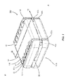
- Figure 1 is an isometric view of a spinal implant for placement in a disc space between adjacent vertebral bodies;
- Figure 2 is an exploded, isometric view of the spinal implant of Figure 1 ;
- Figure 3 is a cross-sectional, isometric view of implant along and in the direction of line III-III of Figure 1 ;
- Figure 4 is an isometric view of the core of the implant of Figure 1 ;
- Figure 5 is an isometric view of the second component of the implant of Figure 1 ;
- Figure 6 is a front view of the implant of Figure 1 after it is implanted in a disc space between adjacent vertebral bodies;
- Figure 7 is a cross-sectional, isometric view of an implant
- Figure 7A is an isometric view of a core of the implant of Figure 7 ;
- Figure 7B is an isometric view of a second component of the implant of Figure 7 ;
- Figure 8 is a cross-sectional, isometric view of an implant
- Figure 8A is an isometric view of a core of the implant of Figure 8 ;
- Figure 8B is an isometric view of a second component of the implant of Figure 8 ;
- Figure 9 is a cross-sectional, isometric view of an implant
- Figure 9A is an isometric view of a core of the implant of Figure 9 ;
- Figure 9B is an isometric view of a second component of the implant of Figure 9 ;
- Figure 10 is a cross-sectional, isometric view of an implant
- Figure 10A is an isometric view of a core of the implant of Figure 10 ;
- Figure 10B is an isometric view of a second component of the implant of Figure 10 ;
- Figure 11 is a cross-sectional, isometric view of an implant
- Figure 11A is an isometric view of a core of the implant of Figure 11 ;
- Figure 11B is an isometric view of a second component of the implant of Figure 11 ;
- Figure 12 is a cross-sectional, isometric view of an implant
- Figure 12A is an isometric view of a core of the implant of Figure 12 ;
- Figure 12B is an isometric view of a second component of the implant of Figure 12 .
- FIG 1 shows an isometric view of a spinal implant 100 for placement in a disc space between adjacent vertebral bodies.
- the implant 100 comprises a first component 10, a second component 10A, a core 30 and a tether 40.
- the tether 40 comprises a first tether component 40A and a second tether component 40B.
- the first component 10 comprises a first exterior surface 10E configured for engaging a first vertebra, and a first interior surface opposing the first exterior surface 10E.
- the second component 10A comprises a second exterior surface configured for engaging a second vertebra, and a second interior surface opposing the second exterior surface.
- the core 30 is configured to interface with the first interior surface and the second interior surface.
- the tether 40 is configured to contact the first component 10 and the second component 10A, wherein the tether 40 is material for maintaining the core 30 in place between the first and second components 10 and 10A, and wherein the tether 40 is not configured to attach to the first component 10 or the second component 10A.
- the core 30 is not attached to the first interior surface or the second interior surface.
- the core 30 is not attached to the first component 10 or the second component 10A.
- the tether 40 is not attached to the first component 10 or the second component 10A. Further, as shown in Figure 1 , the tether 40 is not attached to the core 30.
- the tether 40 is configured to contact the first exterior surface 10E and the second exterior surface. More specifically, as shown in Figure 1 , the first component 10 has a first recess 12 and a second recess 14 for maintaining the tether 40 in position for maintaining the core 30 in place between the first interior surface and the second interior surface. Similarly, as shown in Figure 1 , the second component 10A has a first recess 12A and a second recess 14A for maintaining the tether 40 in position for maintaining the core 30 in place between the first interior surface and the second interior surface.
- implant 100 further comprises structures 11 to help affix the first component 10 to a vertebral body.
- Structure 11 may be anchors, keels, spikes, pegs, teeth, prongs, ridges, or similar structures to help component 10 affix to a vertebral body.
- structures 11 are shown as a plurality or ridge of teeth.
- structures 11A help affix the second component 10A to a vertebral body.
- reference marker A represents an anterior side of a vertebral body
- reference marker P represents a posterior side of a vertebral body after implant 100 is implanted in its intended position.
- implant 100 may be inserted from the anterior side of the vertebral bodies with a posterior side of the implant 100 (the side closer to reference marker P) entering the disc space prior to an anterior side of the implant 100 (the side closer to reference marker A).
- Surface coatings such as Hydroxyapatite (HA), plasma spray or beading also may be used instead of or in addition to respective structure 11 or 11A to help affix their respective components 10 or 10A to their respective vertebral bodies.
- FIG 2 shows an exploded, isometric view of the spinal implant 100 of Figure 1 .
- the implant 100 comprises a first component 10, a second component 10A, a core 30 and a tether 40.
- the core 30 comprises a first core component 32 and a second core component 42.
- the first core component 32 and the second core component 42 are distinct portions of the core 30 and are not attached to each other.
- the first core component 32 is located in the substantial center of the implant 100.
- first tether component 40A and the second tether component 40B are distinct portions of the tether 40 and are not attached to each other.
- the tether components 40A and 40B not being attached to each other and not attached to the first and second components 10 and 10A may help in manufacturing of the implant 100, may help provide improved motion of the implant 100 and may help better control rotational movements of the implant 100.
- the first tether component 40A and the second tether component 40B have areas 40AX and 40BX, respectively, in order to form respective loops of tether material.
- Areas 40AX and 40BX may represent a knot, fusing together or other manner of joining the tether material, but note that the first tether component 40A and the second tether component 40B may not need distinct areas such as areas 40AX and 40BX that are schematically shown larger than the other portions of the tethers 40A and 40B, respectively, to form respective loops of tether material.
- first core component 32 is not necessarily located in the exact center of the implant 100, it is located in the substantial center of the implant 100. Specifically, the exact center in all planes of the implant 100 may be difficult to determine, but at least in the embodiment of Figure 2 as shown, the first core component is located in the substantial center of the implant 100, and in the case of spinal implants, this location of the first core component 32 helps the implant 100 properly perform one of its functions of maintaining disc height (i.e., the proper distance between the adjacent vertebrae).
- the spinal implant 100 may serve as a fusion device or may serve as a motion-preserving device.
- the first core component 32 and the second core component 42 provide a degree of flexibility or compliance to the spinal implant 100.
- the first core component 32 and the second core component 42 may be made of the same material or may be made of different materials. Suitable materials include, but are not limited to, any one or any combination of a metal, polymer, ceramic, or other biocompatible material.
- a suitable material for the first core component 32 and/or the second core component 42 may be a viscoelastic material, and more specifically, may be any one or combination of polycarbonurethane ("PCU"), polyurethane ("PU”), polyethelene, silicone and hydrogel.
- PCU polycarbonurethane
- PU polyurethane
- the first core component 32 and the second core component 42 may have different material properties.
- the first core component 32 may be harder than the second core component 42.
- the first core component 32 may help maintain disc height and the second core component 42 may help balance the implant 100 and help the implant's overall motion, e.g., help it achieve desired flexion, extension and rotation.
- the first component 10 and the second component 10A may be made of any metal or non-metal biocompatible material. Suitable materials include, but are not limited to, any one or combination of Titanium Alloys, commercially available Titanium, stainless steel, polyetheretherketone (“PEEK”), cobalt chrome (“CoCr”), polyethylene, and ultra high molecular weight polyethylene (“UHMWPE”).
- Suitable materials include, but are not limited to, any one or combination of Titanium Alloys, commercially available Titanium, stainless steel, polyetheretherketone (“PEEK”), cobalt chrome (“CoCr”), polyethylene, and ultra high molecular weight polyethylene (“UHMWPE”).
- the tether 40 may be made of any one or combination of a cloth, metal, solid polymer, fabric, mesh, or other biocompatible material. Some polymer materials may include any one or combination of polyethylene, polyester, polyvinyl, polyvinyl alcohol, polyacrylonitrile, polyamide, polytetrafluoroethylene, poly-paraphenylene and terephthalamide. Further, the tether 40 may be made of a suture wire of polyester or polyethylene. In addition, the material for the tether 40 may be elastic, woven, knitted, braided or flexible.
- Some woven, knitted or braided materials may, for example, include nylon, Dacron®, and/or woven fibers or filaments of polyester, polyethelene, polypropylene, polyetheretherketone ("PEEK”), polytetrafluoroethylene (“PTFE”), woven PEEK, and/or Bionate® or Pursil® manufactured by DMS PTG, Inc. of Berkeley, California.
- Some elastic materials may, for example, include latex, rubber, silicone, polyurethane, silicone-polyurethane copolymers, and/or polyolefin rubbers.
- suitable materials may, for example, include Gore-Tex®, Kevlar®, Spectra, polyether, polycarbonate urethane, shape memory material with pseudo elastic or superelastic characteristics, metals, metal alloys, and polymers, braided polymers, synthetic resorbable materials such as polyactide, polygycolide, polyorthoester, calcium phosphate, and/or glass, nonresorbable polyethylene, cellulose, materials that are potentially absorbable, and/or materials that are used in making artificial ligaments. Further, suitable materials should be non-biodegradable and non-resorbable. In addition to woven, braided, or knitted structures, the tether 40 also may be composed of non-woven structures such as non-woven mesh, or chained structures.
- Figure 3 shows a cross-sectional, isometric view of implant 100 along and in the direction of line III-III of Figure 1 .
- Figure 3 shows the first exterior surface 10E and the first interior surface 10I of the first component 10.
- the first exterior surface 10E comprises the structures 11 and the second recess 14.
- second tether component 40B Also visible in Figure 3 is second tether component 40B.
- the first interior surface 10I comprises a first central inner surface 5, a first annular inner surface 7, and a first separation surface 6 located between the central inner surface 5 and the annular inner surface 7.
- the first interior surface 10I further comprises a first wall surface 9.
- first wall surface 9 comprises two constituent wall surfaces.
- First wall surface 9 may take on other shapes or forms and may, for example, comprise a single wall surface situated at a right angle to annular surface 7.
- first interior surface 10I and its constituent surfaces may take on different shapes and forms than that shown in Figure 3 .
- interior surface 10I helps maintain the core 30 in place between the first and second components 10 and 10A and helps maintain the core components 32 and 42 in proper position.
- Figure 3 shows the second exterior surface 10AE and the second interior surface 10AI of the second component 10A.
- the second interior surface 10AI comprises a second central inner surface 5A, a second annular inner surface 7A, and a second separation surface 6A located between the second central inner surface 5A and the second annular inner surface 7A.
- the second interior surface 10AI further comprises a second wall surface 9A.
- second wall surface 9A comprises two constituent wall surfaces.
- second wall surface 9A may take on other shapes or forms and may, for example, comprise a single wall surface situated at a right angle to annular surface 7A.
- second interior surface 10AI and its constituent surfaces may take on different shapes and forms than that shown in Figure 3 .
- interior surface 10AI helps maintain the core 30 in place between the first and second components 10 and 10A and helps maintain the core components 32 and 42 in proper position.
- Figure 3 shows that the first core component 32 and the second core component 42.
- the first core component 32 comprises a superior surface 31 and an inferior surface 33.
- the second core component 42 comprises a superior surface 41 and an inferior surface 43.
- the superior surface 31 of the first core component 32 contacts the first central inner surface 5, and the inferior surface 33 of the first core component 32 contacts the second central inner surface 5A.
- the superior surface 41 of the second core component 42 contacts the first annular inner surface 7, and the inferior surface 43 of the second core component 42 contacts the second annular inner surface 7A.
- Implant 100 as shown in Figure 3 is designed for a disc space requiring a certain amount of lordosis. That is, the thickness of the first component 10 and the second component 10A increases from the posterior side to the anterior side. Specifically, with respect to the first component 10, for example, the distance between the first exterior surface 10E and the first interior surface 10I increases from the posterior side to the anterior side.
- implant 100 as shown is designed to accommodate a disc space having a certain amount of lordosis
- implant 100 may be designed to accommodate a disc space having a certain amount of kyphosis (wherein the thickness of implant 100 or either one or both of components 10 and 10A decreases from the posterior side to the anterior side) or neither lordosis or kyphosis (wherein the thickness of implant 100 and the thickness of each of the components 10 and 10A does not vary from the posterior side to the anterior side).
- Figure 4 shows an isometric view of the core 30 of implant 100. Specifically, Figure 4 shows the first core component 32 and the second core component 42. Further, Figure 4 shows the superior surface 31 of the first core component 32 as well as the superior surface 41 and inferior surface 43 of the second core component 42.
- Figure 5 shows an isometric view of the second component 10A of implant 100. Specifically, Figure 5 shows the second interior surface 10AI of the second component 10A. Figure 5 further shows the second wall surface 9A, the second central inner surface 5A, the second annular inner surface 7A, and the second separation surface 6A located between the second central inner surface 5A and the second annular inner surface 7A. Also, Figure 5 shows respective parts of the first recess 12A and the second recess 14A for maintaining the tether 40 in position for maintaining the core 30 in place between the first interior surface 10I and the second interior surface 10AI.
- the parts of the recesses 12A and 14A that are located on the anterior side of the implant 100 are larger than those parts of the recesses 12A and 14A that are located on the posterior side of the implant 100.
- the larger parts of recesses 12A and 14A are intended to accommodate areas 40AX and 40BX of tether 40, respectively.
- Figure 6 shows a front view of spinal implant 100 in its intended position after it is implanted in a disc space 50 between adjacent vertebral bodies V1 and V2. Specifically, Figure 6 shows implant 100 in position between vertebral bodies V1 and V2 from the anterior direction A. As depicted in Figure 6 , reference markers L represent lateral sides of the vertebral bodies V1 and V2.
- Figure 6 shows the first component 10, the second component 10A, the core 30 and the tether 40.
- Figure 6 shows the second core component 42 of core 30 and the first tether component 40A and the second tether component 40B of tether 40.
- the first exterior surface 10E engages vertebral body V1 and the second exterior surface 10AE engages second vertebral body V2.
- FIG. 6 shows structures 11 and 11A to help respective components 10 and 10A affix to vertebral bodies V1 and V2, respectively.
- disc space 50 comprises tissue 52.
- tissue 52 may comprise, for example, annulus fibrosus tissue that surrounds nucleus pulposus tissue of an intervertebral disc.
- first and second interior surface 101 and 10AI and its constituent surfaces may have different shapes and forms than that shown in those previous figures.
- Figures 7-12 show various implants, each depicting a different embodiment of first and second interior surfaces and core combinations.
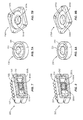
- Figure 7 shows a cross-sectional, isometric view of implant 200 (along and in the direction of a line similar to that of III-III of Figure 1 ).
- Figure 7A shows an isometric view of a core 130 of implant 200.
- Figure 7B shows an isometric view of a second component 110A of implant 200.
- Figures 7 and 7A show a core 130 that comprises a first core component 132 and a second core component 142.
- Figures 7 and 7A show a superior surface 131 of the first core component 132 and the superior surface 131 has a substantially concave shape.
- Figures 7 and 7A show a superior surface 141 of the second core component 142 and the superior surface 141 has a substantially flat shape.
- Figure 7 shows a first central inner surface 105, a first annular inner surface 107, and a first angled wall 104 adjacent the central inner surface 105.
- Figures 7 and 7B show a second central inner surface 105A, a second annular inner surface 107A, and a second angled wall 104A adjacent the central inner surface 105A.
- central inner surfaces 105 and 105A are shaped (specifically having substantially convex surfaces) to accommodate the first core component 132
- annular surfaces 107 and 107A are shaped (specifically having substantially flat surfaces) to accommodate the second core component 142.
- the angled walls 104 and 104A may, for example, help contain the first core component 132 in its intended position, i.e., at the substantial center of implant 200.
- Figure 8 shows a cross-sectional, isometric view of implant 300 (along and in the direction of a line similar to that of III-III of Figure 1 ).
- Figure 8A shows an isometric view of a core 230 of implant 300.
- Figure 8B shows an isometric view of a second component 210A of implant 300.
- Figures 8 and 8A show a core 230 that comprises a first core component 232 and a second core component 242.
- Figures 8 and 8A show a superior surface 231 of the first core component 232 and the superior surface 231 has a substantially convex shape.
- Figures 8 and 8A show a superior surface 241 of the second core component 242 and the superior surface 241 has a substantially flat shape.
- Figure 8 shows a first central inner surface 205, a first annular inner surface 207, and a first angled wall 204 adjacent the central inner surface 205.
- Figures 7 and 7B show a second central inner surface 205A, a second annular inner surface 207A, and a second angled wall 204A adjacent the second central inner surface 205A.
- central inner surfaces 205 and 205A are shaped (specifically having substantially concave surfaces) to accommodate the first core component 232
- annular surfaces 207 and 207A are shaped (specifically having substantially flat surfaces) to accommodate the second core component 242.
- the angled walls 204 and 204A may, for example, help contain first core component 232 in its intended position, i.e., at the substantial center of implant 300.
- Figure 9 shows a cross-sectional, isometric view of implant 400 (along and in the direction of a line similar to that of III-III of Figure 1 ).
- Figure 9A shows an isometric view of a core 330 of implant 400.
- Figure 9B shows an isometric view of a second component 310A of implant 400.
- Figures 9 and 9A show a core 330 that comprises a first core component 332, a second core component 342 and core members 335 connecting the first core component 332 to the second core component 342.
- Figures 9 and 9A show a superior surface 331 of the first core component 332 and the superior surface 331 has a substantially flat shape.
- Figures 9 and 9A show a superior surface 341 of the second core component 342 and the superior surface 341 has a substantially flat shape. Also, Figure 9 shows a first inner surface 307, and Figures 9 and 9B show a second inner surface 307A. As shown in Figures 9, 9A and 9B , inner surfaces 307 and 307A are shaped (specifically having substantially flat surfaces) to accommodate the first core component 332 and the second core component 342.
- Figure 10 shows a cross-sectional, isometric view of implant 500 (along and in the direction of a line similar to that of III-III of Figure 1 ).
- Figure 10A shows an isometric view of a core 430 of implant 500.
- Figure 10B shows an isometric view of a second component 410A of implant 500.
- Figures 10 and 10A show a core 430 that comprises a first core component 432, a second core component 442 and a core member 435 connecting the first core component 432 to the second core component 442.
- Figures 10 and 10A show a superior surface 431 of the first core component 432 and the superior surface 431 has a substantially flat shape.
- Figures 10 and 10A shows a superior surface 441 of the second core component 442 and the superior surface 441 has a substantially flat shape. Also, Figure 10 shows a first inner surface 407, and Figures 10 and 10B show a second inner surface 407A. As shown in Figures 10, 10A and 10B , inner surfaces 407 and 407A are shaped (having substantially flat surfaces) to accommodate the first core component 432 and the second core component 442.
- Figure 11 shows a cross-sectional, isometric view of implant 600 (along and in the direction of a line similar to that of III-III of Figure 1 ).
- Figure 11A shows an isometric view of a core 530 of implant 600.
- Figure 11B shows an isometric view of a second component 510A of implant 600.
- Figures 11 and 11A show a core 530 that comprises a first core component 532 and a second core component 542.
- Figures 11 and 11A show a first superior surface 531 and a second superior surface 533 of the first core component 532 and both the first superior surface 531 and the second superior surface 533 are substantially flat.
- Figures 11 and 11A show a superior surface 541 of the second core component 542 and the superior surface 541 has a substantially flat shape. Also, Figure 11 shows a first central inner surface 505, a first annular inner surface 507, and a first separation surface 506 located between the first central inner surface 505 and the first annular inner surface 507. Similarly, Figures 11 and 11B show a second central inner surface 505A, a second annular inner surface 507A, and a second separation surface 506A located between the second central inner surface 505A and the second annular inner surface 507A.
- central inner surfaces 505 and 505A and separation surfaces 506 and 506A are shaped (having substantially flat surfaces) to accommodate the first core component 532
- annular surfaces 507 and 507A are shaped (having substantially flat surfaces) to accommodate the second core component 542.
- the central inner surfaces 505 and 505A and separation surfaces 506 and 506A, and their respective orientation to each other may, for example, help contain the first core component 532 in its intended position, i.e., at the substantial center of implant 600.
- Figure 12 shows a cross-sectional, isometric view of implant 600 (along and in the direction of a line similar to that of III-III of Figure 1 ).
- Figure 12A shows an isometric view of a core 630 of implant 700.
- Figure 12B shows an isometric view of a second component 610A of implant 700.
- Figures 12 and 12A show a core 630 that comprises a first core component 632 and a second core component 642.
- Figures 12 and 12A show a first superior surface 631 and a second superior surface 633 of the first core component 632 and both the first superior surface 631 and the second superior surface 633 have substantially flat shapes.
- Figures 12 and 12A show a superior surface 641 of the second core component 642 and the superior surface 641 has a substantially flat shape. Also, Figure 12 shows a first central inner surface 605, a first annular inner surface 607, and a first separation surface 606 located between the first central inner surface 605 and the first annular inner surface 607. Similarly, Figures 12 and 12B show a second central inner surface 605A, a second annular inner surface 607A, and a second separation surface 606A located between the second central inner surface 605A and the second annular inner surface 607A.
- central inner surfaces 605 and 605A and separation surfaces 606 and 606A are shaped (having substantially flat surfaces) to accommodate the first core component 632
- annular surfaces 607 and 607A are shaped (having substantially flat surfaces) to accommodate the second core component 642.
- the central inner surfaces 605 and 605A and separation surfaces 606 and 606A, and their respective orientation to each other may, for example, help contain first core component 632 in its intended position, i.e., at the substantial center of implant 700.
- prostheses 100, 200, 300, 400, 500, 600 and 700 are shown as motion-preserving devices, but can be modified to be fusion devices.
- all of the prostheses above are described as being configured to affix to an endplate of a vertebral body and a vertical surface of a vertebral body that is an anterior surface of a vertebral body, all of the prostheses above may be configured to affix to a posterior surface of a vertebral body, a lateral surface of a vertebral body instead of or as well as an anterior surface of a vertebral body, or any plurality or combination or such surfaces.
Landscapes
- Health & Medical Sciences (AREA)
- Engineering & Computer Science (AREA)
- Biomedical Technology (AREA)
- Neurology (AREA)
- Orthopedic Medicine & Surgery (AREA)
- Cardiology (AREA)
- Oral & Maxillofacial Surgery (AREA)
- Transplantation (AREA)
- Heart & Thoracic Surgery (AREA)
- Vascular Medicine (AREA)
- Life Sciences & Earth Sciences (AREA)
- Animal Behavior & Ethology (AREA)
- General Health & Medical Sciences (AREA)
- Public Health (AREA)
- Veterinary Medicine (AREA)
- Prostheses (AREA)
Abstract
Description
- The present invention is directed to spinal implants.
- The present disclosure relates to spinal implants, and particularly, spinal implants for intervertebral space.
- A spinal implant is disclosed. The spinal implant comprises a first component, a second component, a core and a tether. The first component comprises a first exterior surface configured for engaging a first vertebra, and a first interior surface opposing the first exterior surface. The second component comprises a second exterior surface configured for engaging a second vertebra, and a second interior surface opposing the second exterior surface. The core is configured to interface with the first interior surface and the second interior surface, and the tether configured to contact the first component and the second component. The tether is material for maintaining the core in place between the first and second components, and the tether is not configured to attach to the first component or the second component.
- Additional aspects and features of the present disclosure will be apparent from the detailed description and claims as set forth below.
-
Figure 1 is an isometric view of a spinal implant for placement in a disc space between adjacent vertebral bodies; -
Figure 2 is an exploded, isometric view of the spinal implant ofFigure 1 ; -
Figure 3 is a cross-sectional, isometric view of implant along and in the direction of line III-III ofFigure 1 ; -
Figure 4 is an isometric view of the core of the implant ofFigure 1 ; -
Figure 5 is an isometric view of the second component of the implant ofFigure 1 ; -
Figure 6 is a front view of the implant ofFigure 1 after it is implanted in a disc space between adjacent vertebral bodies; -
Figure 7 is a cross-sectional, isometric view of an implant; -
Figure 7A is an isometric view of a core of the implant ofFigure 7 ; -
Figure 7B is an isometric view of a second component of the implant ofFigure 7 ; -
Figure 8 is a cross-sectional, isometric view of an implant; -
Figure 8A is an isometric view of a core of the implant ofFigure 8 ; -
Figure 8B is an isometric view of a second component of the implant ofFigure 8 ; -
Figure 9 is a cross-sectional, isometric view of an implant; -
Figure 9A is an isometric view of a core of the implant ofFigure 9 ; -
Figure 9B is an isometric view of a second component of the implant ofFigure 9 ; -
Figure 10 is a cross-sectional, isometric view of an implant; -
Figure 10A is an isometric view of a core of the implant ofFigure 10 ; -
Figure 10B is an isometric view of a second component of the implant ofFigure 10 ; -
Figure 11 is a cross-sectional, isometric view of an implant; -
Figure 11A is an isometric view of a core of the implant ofFigure 11 ; -
Figure 11B is an isometric view of a second component of the implant ofFigure 11 ; -
Figure 12 is a cross-sectional, isometric view of an implant; -
Figure 12A is an isometric view of a core of the implant ofFigure 12 ; and -
Figure 12B is an isometric view of a second component of the implant ofFigure 12 . - For the purposes of promoting an understanding of the principles of the invention, reference will now be made to the embodiments, or examples, illustrated in the drawings and specific language will be used to describe the same. It will nevertheless be understood that no limitation of the scope of the invention is thereby intended. Any alterations and further modifications in the described embodiments, and any further applications of the principles of the invention as described herein are contemplated as would normally occur to one skilled in the art to which the invention relates.
-
Figure 1 shows an isometric view of aspinal implant 100 for placement in a disc space between adjacent vertebral bodies. Theimplant 100 comprises afirst component 10, asecond component 10A, acore 30 and atether 40. As shown inFigure 1 , thetether 40 comprises afirst tether component 40A and asecond tether component 40B. Thefirst component 10 comprises a firstexterior surface 10E configured for engaging a first vertebra, and a first interior surface opposing the firstexterior surface 10E. Thesecond component 10A comprises a second exterior surface configured for engaging a second vertebra, and a second interior surface opposing the second exterior surface. Thecore 30 is configured to interface with the first interior surface and the second interior surface. Thetether 40 is configured to contact thefirst component 10 and thesecond component 10A, wherein thetether 40 is material for maintaining thecore 30 in place between the first andsecond components tether 40 is not configured to attach to thefirst component 10 or thesecond component 10A. - As shown in
implant 100 ofFigure 1 , thecore 30 is not attached to the first interior surface or the second interior surface. Thus, as shown, thecore 30 is not attached to thefirst component 10 or thesecond component 10A. Also, as shown inFigure 1 , thetether 40 is not attached to thefirst component 10 or thesecond component 10A. Further, as shown inFigure 1 , thetether 40 is not attached to thecore 30. - As shown in
Figure 1 , thetether 40 is configured to contact the firstexterior surface 10E and the second exterior surface. More specifically, as shown inFigure 1 , thefirst component 10 has afirst recess 12 and asecond recess 14 for maintaining thetether 40 in position for maintaining thecore 30 in place between the first interior surface and the second interior surface. Similarly, as shown inFigure 1 , thesecond component 10A has afirst recess 12A and asecond recess 14A for maintaining thetether 40 in position for maintaining thecore 30 in place between the first interior surface and the second interior surface. - As shown in
Figure 1 ,implant 100 further comprisesstructures 11 to help affix thefirst component 10 to a vertebral body.Structure 11 may be anchors, keels, spikes, pegs, teeth, prongs, ridges, or similar structures to help component 10 affix to a vertebral body. As shown inFigure 1 ,structures 11 are shown as a plurality or ridge of teeth. Similarly, as shown,structures 11A help affix thesecond component 10A to a vertebral body. As depicted inFigure 1 , reference marker A represents an anterior side of a vertebral body, whereas reference marker P represents a posterior side of a vertebral body afterimplant 100 is implanted in its intended position. Specifically, as shown,implant 100 may be inserted from the anterior side of the vertebral bodies with a posterior side of the implant 100 (the side closer to reference marker P) entering the disc space prior to an anterior side of the implant 100 (the side closer to reference marker A). Surface coatings such as Hydroxyapatite (HA), plasma spray or beading also may be used instead of or in addition torespective structure respective components -
Figure 2 shows an exploded, isometric view of thespinal implant 100 ofFigure 1 . Theimplant 100 comprises afirst component 10, asecond component 10A, acore 30 and atether 40. As shown inFigure 2 , thecore 30 comprises afirst core component 32 and asecond core component 42. Also, as schematically shown inFigure 2 , thefirst core component 32 and thesecond core component 42 are distinct portions of thecore 30 and are not attached to each other. Further, as shown inFigure 2 , thefirst core component 32 is located in the substantial center of theimplant 100. - Also, as shown in
Figure 2 , thefirst tether component 40A and thesecond tether component 40B are distinct portions of thetether 40 and are not attached to each other. Thetether components second components implant 100, may help provide improved motion of theimplant 100 and may help better control rotational movements of theimplant 100. Also, as shown inFigure 2 , thefirst tether component 40A and thesecond tether component 40B have areas 40AX and 40BX, respectively, in order to form respective loops of tether material. Areas 40AX and 40BX may represent a knot, fusing together or other manner of joining the tether material, but note that thefirst tether component 40A and thesecond tether component 40B may not need distinct areas such as areas 40AX and 40BX that are schematically shown larger than the other portions of thetethers - The term "substantial" (or "substantially") as used herein may be applied to modify any quantitative representation which could permissibly vary without resulting in a change in the basic function to which it is related. For example, while the
first core component 32 is not necessarily located in the exact center of theimplant 100, it is located in the substantial center of theimplant 100. Specifically, the exact center in all planes of theimplant 100 may be difficult to determine, but at least in the embodiment ofFigure 2 as shown, the first core component is located in the substantial center of theimplant 100, and in the case of spinal implants, this location of thefirst core component 32 helps theimplant 100 properly perform one of its functions of maintaining disc height (i.e., the proper distance between the adjacent vertebrae). - The
spinal implant 100 may serve as a fusion device or may serve as a motion-preserving device. In the case of a motion-preserving implant, thefirst core component 32 and thesecond core component 42 provide a degree of flexibility or compliance to thespinal implant 100. Thefirst core component 32 and thesecond core component 42 may be made of the same material or may be made of different materials. Suitable materials include, but are not limited to, any one or any combination of a metal, polymer, ceramic, or other biocompatible material. In the case of a motion-preserving implant, a suitable material for thefirst core component 32 and/or thesecond core component 42 may be a viscoelastic material, and more specifically, may be any one or combination of polycarbonurethane ("PCU"), polyurethane ("PU"), polyethelene, silicone and hydrogel. Further, thefirst core component 32 and thesecond core component 42 may have different material properties. For example, if made of the same or different materials, thefirst core component 32 may be harder than thesecond core component 42. When, for example, thefirst core component 32 is harder than thesecond component 42, thefirst core component 32 may help maintain disc height and thesecond core component 42 may help balance theimplant 100 and help the implant's overall motion, e.g., help it achieve desired flexion, extension and rotation. - The
first component 10 and thesecond component 10A may be made of any metal or non-metal biocompatible material. Suitable materials include, but are not limited to, any one or combination of Titanium Alloys, commercially available Titanium, stainless steel, polyetheretherketone ("PEEK"), cobalt chrome ("CoCr"), polyethylene, and ultra high molecular weight polyethylene ("UHMWPE"). - The
tether 40 may be made of any one or combination of a cloth, metal, solid polymer, fabric, mesh, or other biocompatible material. Some polymer materials may include any one or combination of polyethylene, polyester, polyvinyl, polyvinyl alcohol, polyacrylonitrile, polyamide, polytetrafluoroethylene, poly-paraphenylene and terephthalamide. Further, thetether 40 may be made of a suture wire of polyester or polyethylene. In addition, the material for thetether 40 may be elastic, woven, knitted, braided or flexible. Some woven, knitted or braided materials may, for example, include nylon, Dacron®, and/or woven fibers or filaments of polyester, polyethelene, polypropylene, polyetheretherketone ("PEEK"), polytetrafluoroethylene ("PTFE"), woven PEEK, and/or Bionate® or Pursil® manufactured by DMS PTG, Inc. of Berkeley, California. Some elastic materials may, for example, include latex, rubber, silicone, polyurethane, silicone-polyurethane copolymers, and/or polyolefin rubbers. Other suitable materials may, for example, include Gore-Tex®, Kevlar®, Spectra, polyether, polycarbonate urethane, shape memory material with pseudo elastic or superelastic characteristics, metals, metal alloys, and polymers, braided polymers, synthetic resorbable materials such as polyactide, polygycolide, polyorthoester, calcium phosphate, and/or glass, nonresorbable polyethylene, cellulose, materials that are potentially absorbable, and/or materials that are used in making artificial ligaments. Further, suitable materials should be non-biodegradable and non-resorbable. In addition to woven, braided, or knitted structures, thetether 40 also may be composed of non-woven structures such as non-woven mesh, or chained structures. -
Figure 3 shows a cross-sectional, isometric view ofimplant 100 along and in the direction of line III-III ofFigure 1 .Figure 3 shows the firstexterior surface 10E and the first interior surface 10I of thefirst component 10. As shown inFigure 3 , the firstexterior surface 10E comprises thestructures 11 and thesecond recess 14. Also visible inFigure 3 issecond tether component 40B. As shown inFigure 3 , the first interior surface 10I comprises a first centralinner surface 5, a first annularinner surface 7, and afirst separation surface 6 located between the centralinner surface 5 and the annularinner surface 7. Also, as shown inFigure 3 , the first interior surface 10I further comprises afirst wall surface 9. As shown inFigure 3 ,first wall surface 9 comprises two constituent wall surfaces.First wall surface 9, however, may take on other shapes or forms and may, for example, comprise a single wall surface situated at a right angle toannular surface 7. Similarly, first interior surface 10I and its constituent surfaces may take on different shapes and forms than that shown inFigure 3 . As shown inFigure 3 , interior surface 10I helps maintain the core 30 in place between the first andsecond components core components - Also,
Figure 3 shows the second exterior surface 10AE and the second interior surface 10AI of thesecond component 10A. As shown inFigure 3 , the second interior surface 10AI comprises a second centralinner surface 5A, a second annularinner surface 7A, and asecond separation surface 6A located between the second centralinner surface 5A and the second annularinner surface 7A. Also, as shown inFigure 3 , the second interior surface 10AI further comprises asecond wall surface 9A. As shown inFigure 3 , and as withfirst wall surface 9,second wall surface 9A comprises two constituent wall surfaces. Similarly,second wall surface 9A, however, may take on other shapes or forms and may, for example, comprise a single wall surface situated at a right angle toannular surface 7A. Similarly, second interior surface 10AI and its constituent surfaces may take on different shapes and forms than that shown inFigure 3 . As shown inFigure 3 , interior surface 10AI helps maintain the core 30 in place between the first andsecond components core components - Also,
Figure 3 shows that thefirst core component 32 and thesecond core component 42. As shown inFigure 3 , thefirst core component 32 comprises asuperior surface 31 and aninferior surface 33. Similarly, thesecond core component 42 comprises asuperior surface 41 and aninferior surface 43. As shown inFigure 3 , thesuperior surface 31 of thefirst core component 32 contacts the first centralinner surface 5, and theinferior surface 33 of thefirst core component 32 contacts the second centralinner surface 5A. Further, as shown inFigure 3 , thesuperior surface 41 of thesecond core component 42 contacts the first annularinner surface 7, and theinferior surface 43 of thesecond core component 42 contacts the second annularinner surface 7A. -
Implant 100 as shown inFigure 3 is designed for a disc space requiring a certain amount of lordosis. That is, the thickness of thefirst component 10 and thesecond component 10A increases from the posterior side to the anterior side. Specifically, with respect to thefirst component 10, for example, the distance between the firstexterior surface 10E and the first interior surface 10I increases from the posterior side to the anterior side. Althoughimplant 100 as shown is designed to accommodate a disc space having a certain amount of lordosis,implant 100 may be designed to accommodate a disc space having a certain amount of kyphosis (wherein the thickness ofimplant 100 or either one or both ofcomponents implant 100 and the thickness of each of thecomponents -
Figure 4 shows an isometric view of thecore 30 ofimplant 100. Specifically,Figure 4 shows thefirst core component 32 and thesecond core component 42. Further,Figure 4 shows thesuperior surface 31 of thefirst core component 32 as well as thesuperior surface 41 andinferior surface 43 of thesecond core component 42. -
Figure 5 shows an isometric view of thesecond component 10A ofimplant 100. Specifically,Figure 5 shows the second interior surface 10AI of thesecond component 10A.Figure 5 further shows thesecond wall surface 9A, the second centralinner surface 5A, the second annularinner surface 7A, and thesecond separation surface 6A located between the second centralinner surface 5A and the second annularinner surface 7A. Also,Figure 5 shows respective parts of thefirst recess 12A and thesecond recess 14A for maintaining thetether 40 in position for maintaining the core 30 in place between the first interior surface 10I and the second interior surface 10AI. As shown inFigure 5 , the parts of therecesses implant 100 are larger than those parts of therecesses implant 100. In the case ofimplant 100, the larger parts ofrecesses tether 40, respectively. Note that it is possible to form thefirst tether component 40A and asecond tether component 40B with a constant cross-sectional area or thickness throughout so that the parts of therecesses implant 100 may be of the same size of the parts of therecess implant 100. -
Figure 6 shows a front view ofspinal implant 100 in its intended position after it is implanted in adisc space 50 between adjacent vertebral bodies V1 and V2. Specifically,Figure 6 showsimplant 100 in position between vertebral bodies V1 and V2 from the anterior direction A. As depicted inFigure 6 , reference markers L represent lateral sides of the vertebral bodies V1 and V2.Figure 6 shows thefirst component 10, thesecond component 10A, thecore 30 and thetether 40. Specifically,Figure 6 shows thesecond core component 42 ofcore 30 and thefirst tether component 40A and thesecond tether component 40B oftether 40. The firstexterior surface 10E engages vertebral body V1 and the second exterior surface 10AE engages second vertebral body V2. Also,Figure 6 showsstructures respective components Figure 6 ,disc space 50 comprisestissue 52. Note that whileimplant 100 may be implanted in adisc space 50 andcertain tissue 52 may be left intact to, for example, promote healing of the affected area,such tissue 52 may be completely removed so that only implant 100 resides in thedisc space 50 after implantation.Tissue 52 may comprise, for example, annulus fibrosus tissue that surrounds nucleus pulposus tissue of an intervertebral disc. - As mentioned with respect to
Figures 3 ,4 and5 , the first and secondinterior surface 101 and 10AI and its constituent surfaces may have different shapes and forms than that shown in those previous figures. For example,Figures 7-12 show various implants, each depicting a different embodiment of first and second interior surfaces and core combinations. -
Figure 7 shows a cross-sectional, isometric view of implant 200 (along and in the direction of a line similar to that of III-III ofFigure 1 ).Figure 7A shows an isometric view of acore 130 ofimplant 200.Figure 7B shows an isometric view of asecond component 110A ofimplant 200. Specifically,Figures 7 and 7A show a core 130 that comprises afirst core component 132 and asecond core component 142. Further,Figures 7 and 7A show asuperior surface 131 of thefirst core component 132 and thesuperior surface 131 has a substantially concave shape.Figures 7 and 7A show asuperior surface 141 of thesecond core component 142 and thesuperior surface 141 has a substantially flat shape. Also,Figure 7 shows a first centralinner surface 105, a first annularinner surface 107, and a firstangled wall 104 adjacent the centralinner surface 105. Similarly,Figures 7 and 7B show a second centralinner surface 105A, a second annularinner surface 107A, and a secondangled wall 104A adjacent the centralinner surface 105A. As shown inFigures 7, 7A and 7B , centralinner surfaces first core component 132, andannular surfaces second core component 142. Theangled walls first core component 132 in its intended position, i.e., at the substantial center ofimplant 200. -
Figure 8 shows a cross-sectional, isometric view of implant 300 (along and in the direction of a line similar to that of III-III ofFigure 1 ).Figure 8A shows an isometric view of acore 230 ofimplant 300.Figure 8B shows an isometric view of asecond component 210A ofimplant 300. Specifically,Figures 8 and 8A show a core 230 that comprises afirst core component 232 and asecond core component 242. Further,Figures 8 and 8A show asuperior surface 231 of thefirst core component 232 and thesuperior surface 231 has a substantially convex shape.Figures 8 and 8A show asuperior surface 241 of thesecond core component 242 and thesuperior surface 241 has a substantially flat shape. Also,Figure 8 shows a first centralinner surface 205, a first annularinner surface 207, and a firstangled wall 204 adjacent the centralinner surface 205. Similarly,Figures 7 and 7B show a second centralinner surface 205A, a second annularinner surface 207A, and a secondangled wall 204A adjacent the second centralinner surface 205A. As shown inFigures 8, 8A and 8B , centralinner surfaces first core component 232, andannular surfaces second core component 242. Theangled walls first core component 232 in its intended position, i.e., at the substantial center ofimplant 300. -
Figure 9 shows a cross-sectional, isometric view of implant 400 (along and in the direction of a line similar to that of III-III ofFigure 1 ).Figure 9A shows an isometric view of acore 330 ofimplant 400.Figure 9B shows an isometric view of asecond component 310A ofimplant 400. Specifically,Figures 9 and 9A show a core 330 that comprises afirst core component 332, asecond core component 342 andcore members 335 connecting thefirst core component 332 to thesecond core component 342. Further,Figures 9 and 9A show asuperior surface 331 of thefirst core component 332 and thesuperior surface 331 has a substantially flat shape.Figures 9 and 9A show asuperior surface 341 of thesecond core component 342 and thesuperior surface 341 has a substantially flat shape. Also,Figure 9 shows a firstinner surface 307, andFigures 9 and 9B show a secondinner surface 307A. As shown inFigures 9, 9A and 9B ,inner surfaces first core component 332 and thesecond core component 342. -
Figure 10 shows a cross-sectional, isometric view of implant 500 (along and in the direction of a line similar to that of III-III ofFigure 1 ).Figure 10A shows an isometric view of acore 430 ofimplant 500.Figure 10B shows an isometric view of asecond component 410A ofimplant 500. Specifically,Figures 10 and 10A show a core 430 that comprises a first core component 432, asecond core component 442 and acore member 435 connecting the first core component 432 to thesecond core component 442. Further,Figures 10 and 10A show asuperior surface 431 of the first core component 432 and thesuperior surface 431 has a substantially flat shape.Figures 10 and 10A shows asuperior surface 441 of thesecond core component 442 and thesuperior surface 441 has a substantially flat shape. Also,Figure 10 shows a firstinner surface 407, andFigures 10 and 10B show a secondinner surface 407A. As shown inFigures 10, 10A and 10B ,inner surfaces second core component 442. -
Figure 11 shows a cross-sectional, isometric view of implant 600 (along and in the direction of a line similar to that of III-III ofFigure 1 ).Figure 11A shows an isometric view of acore 530 ofimplant 600.Figure 11B shows an isometric view of asecond component 510A ofimplant 600. Specifically,Figures 11 and 11A show a core 530 that comprises afirst core component 532 and asecond core component 542. Further,Figures 11 and 11A show a firstsuperior surface 531 and a secondsuperior surface 533 of thefirst core component 532 and both the firstsuperior surface 531 and the secondsuperior surface 533 are substantially flat.Figures 11 and 11A show asuperior surface 541 of thesecond core component 542 and thesuperior surface 541 has a substantially flat shape. Also,Figure 11 shows a first centralinner surface 505, a first annularinner surface 507, and afirst separation surface 506 located between the first centralinner surface 505 and the first annularinner surface 507. Similarly,Figures 11 and 11B show a second centralinner surface 505A, a second annularinner surface 507A, and asecond separation surface 506A located between the second centralinner surface 505A and the second annularinner surface 507A. As shown inFigures 11, 11A and 11B , centralinner surfaces separation surfaces first core component 532, andannular surfaces second core component 542. The centralinner surfaces separation surfaces first core component 532 in its intended position, i.e., at the substantial center ofimplant 600. -
Figure 12 shows a cross-sectional, isometric view of implant 600 (along and in the direction of a line similar to that of III-III ofFigure 1 ).Figure 12A shows an isometric view of acore 630 ofimplant 700.Figure 12B shows an isometric view of asecond component 610A ofimplant 700. Specifically,Figures 12 and 12A show a core 630 that comprises afirst core component 632 and asecond core component 642. Further,Figures 12 and 12A show a firstsuperior surface 631 and a secondsuperior surface 633 of thefirst core component 632 and both the firstsuperior surface 631 and the secondsuperior surface 633 have substantially flat shapes.Figures 12 and 12A show asuperior surface 641 of thesecond core component 642 and thesuperior surface 641 has a substantially flat shape. Also,Figure 12 shows a first centralinner surface 605, a first annularinner surface 607, and afirst separation surface 606 located between the first centralinner surface 605 and the first annularinner surface 607. Similarly,Figures 12 and 12B show a second centralinner surface 605A, a second annularinner surface 607A, and asecond separation surface 606A located between the second centralinner surface 605A and the second annularinner surface 607A. As shown inFigures 12, 12A and 12B , centralinner surfaces separation surfaces first core component 632, andannular surfaces second core component 642. The centralinner surfaces separation surfaces first core component 632 in its intended position, i.e., at the substantial center ofimplant 700. - All adjustments and alternatives described above are intended to be included within the scope of the invention, as defined exclusively in the following claims. Those skilled in the art also should realize that such modifications and equivalent constructions or methods do not depart from the spirit and scope of the present disclosure, and that they may make various changes, substitutions, and alterations herein without departing from the spirit and scope of the present disclosure. For example,
prostheses - Furthermore, as used herein, the terms components and modules may be interchanged. It is understood that all spatial references, such as "first," "second," "exterior," "interior," "superior," "inferior," "anterior," "posterior," "central," "annular," "outer," and "inner," and are for illustrative purposes only and can be varied within the scope of the disclosure.
Claims (12)
- A spinal implant comprising:a first component comprising:a first exterior surface configured for engaging a first vertebra; anda first interior surface opposing the first exterior surface;a second component comprising:a second exterior surface configured for engaging a second vertebra; anda second interior surface opposing the second exterior surface;a core configured to interface with the first interior surface and the second interior surface; anda tether configured to contact the first component and the second component, wherein the tether is material for maintaining the core in place between the first and second components, and wherein the tether is not configured to attach to the first component or the second component.
- The spinal implant of claim 1, wherein the core is not attached to the first interior surface or the second interior surface.
- The spinal implant of claim 1 or 2, wherein the tether is not attached to the first component or the second component.
- The spinal implant of one of claims 1 to 3, wherein the tether is not attached to the core.
- The spinal implant of one of claims 1 to 4, wherein the core is not attached to the first component or the second component, and wherein the tether is not attached to the first component, the second component or the core.
- The spinal implant of one of claims 1 to 5, wherein the core comprises a first core component and a second core component.
- The spinal implant of claim 6, wherein the first core component and the second core component are distinct portions of the core and are not attached to each other.
- The spinal implant of claim 6 or 7, wherein the first core component is located in the substantial center of the implant and wherein the first core component is preferably harder than the second core component.
- The spinal implant of one of claims 1 to 8, wherein the spinal implant is a fusion device.
- The spinal implant of one of claims 1 to 8, wherein the spinal implant is a motion-preserving device.
- The spinal implant of one of claims 1 to 10, wherein the tether is configured to contact the first exterior surface and the second exterior surface.
- The spinal implant of one of claims 1 to 11, wherein at least one of the first component and the second component further comprise a recess for maintaining the tether in position for maintaining the core in place between the first interior surface and the second interior surface.
Priority Applications (1)
| Application Number | Priority Date | Filing Date | Title |
|---|---|---|---|
| EP20100305406 EP2377495A1 (en) | 2010-04-19 | 2010-04-19 | Spinal implant |
Applications Claiming Priority (1)
| Application Number | Priority Date | Filing Date | Title |
|---|---|---|---|
| EP20100305406 EP2377495A1 (en) | 2010-04-19 | 2010-04-19 | Spinal implant |
Publications (1)
| Publication Number | Publication Date |
|---|---|
| EP2377495A1 true EP2377495A1 (en) | 2011-10-19 |
Family
ID=42814325
Family Applications (1)
| Application Number | Title | Priority Date | Filing Date |
|---|---|---|---|
| EP20100305406 Withdrawn EP2377495A1 (en) | 2010-04-19 | 2010-04-19 | Spinal implant |
Country Status (1)
| Country | Link |
|---|---|
| EP (1) | EP2377495A1 (en) |
Cited By (3)
| Publication number | Priority date | Publication date | Assignee | Title |
|---|---|---|---|---|
| WO2013095813A1 (en) * | 2011-12-20 | 2013-06-27 | Warsaw Orthopedic, Inc. | Spinal implant |
| FR2988995A1 (en) * | 2012-04-05 | 2013-10-11 | Fournitures Hospitalieres Ind | Cervical intervertebral disc prosthesis for replacing damaged cervical intervertebral disc of vertebral column of patient, has attachment unit comprising holding portions on compression cushion, where each portion cooperates with housing |
| US9125753B2 (en) | 2012-02-17 | 2015-09-08 | Ervin Caballes | Elastomeric artificial joints and intervertebral prosthesis systems |
Citations (4)
| Publication number | Priority date | Publication date | Assignee | Title |
|---|---|---|---|---|
| WO2005007041A1 (en) * | 2003-07-22 | 2005-01-27 | Synthes Gmbh | Intervertebral implant comprising temporary blocking means |
| US20050203626A1 (en) * | 2004-03-15 | 2005-09-15 | Sdgi Holdings, Inc. | System and method for stabilizing a prosthetic device |
| US20060136061A1 (en) * | 2003-04-04 | 2006-06-22 | Theken Disc, Llc | Artificial disc prosthesis |
| WO2007028098A2 (en) * | 2005-09-01 | 2007-03-08 | Spinal Kinetics, Inc. | Prosthetic intervertebral discs |
-
2010
- 2010-04-19 EP EP20100305406 patent/EP2377495A1/en not_active Withdrawn
Patent Citations (4)
| Publication number | Priority date | Publication date | Assignee | Title |
|---|---|---|---|---|
| US20060136061A1 (en) * | 2003-04-04 | 2006-06-22 | Theken Disc, Llc | Artificial disc prosthesis |
| WO2005007041A1 (en) * | 2003-07-22 | 2005-01-27 | Synthes Gmbh | Intervertebral implant comprising temporary blocking means |
| US20050203626A1 (en) * | 2004-03-15 | 2005-09-15 | Sdgi Holdings, Inc. | System and method for stabilizing a prosthetic device |
| WO2007028098A2 (en) * | 2005-09-01 | 2007-03-08 | Spinal Kinetics, Inc. | Prosthetic intervertebral discs |
Cited By (4)
| Publication number | Priority date | Publication date | Assignee | Title |
|---|---|---|---|---|
| WO2013095813A1 (en) * | 2011-12-20 | 2013-06-27 | Warsaw Orthopedic, Inc. | Spinal implant |
| US9125753B2 (en) | 2012-02-17 | 2015-09-08 | Ervin Caballes | Elastomeric artificial joints and intervertebral prosthesis systems |
| US9707093B2 (en) | 2012-02-17 | 2017-07-18 | Ervin Caballes | Elastomeric artificial joints and intervertebral prosthesis systems |
| FR2988995A1 (en) * | 2012-04-05 | 2013-10-11 | Fournitures Hospitalieres Ind | Cervical intervertebral disc prosthesis for replacing damaged cervical intervertebral disc of vertebral column of patient, has attachment unit comprising holding portions on compression cushion, where each portion cooperates with housing |
Similar Documents
| Publication | Publication Date | Title |
|---|---|---|
| US8591555B2 (en) | System with integral locking mechanism | |
| US8118873B2 (en) | Total joint replacement | |
| EP1919404B1 (en) | Orthopaedic medical device | |
| US20210338454A1 (en) | 3d printed osteogenesis scaffold | |
| US7927373B2 (en) | Intervertebral disc prosthesis | |
| US8353964B2 (en) | Anatomic total disc replacement | |
| US8202320B2 (en) | Intervertebral disc prosthesis | |
| CA2702964C (en) | Hemi-prosthesis | |
| EP2677972B1 (en) | Six degree spine stabilization devices | |
| EP3027147B1 (en) | Artificial disc devices and related methods of use | |
| EP2278941A1 (en) | Polyaryletherketone artificial intervertebral disc | |
| KR20060106857A (en) | Spinal arthroplasty device and method | |
| US20090138088A1 (en) | Mobile spinal fusion implant | |
| US20090088851A1 (en) | Combination plate and disc prosthesis | |
| KR102803914B1 (en) | Anti-separation Synthetic Disc |
Legal Events
| Date | Code | Title | Description |
|---|---|---|---|
| AK | Designated contracting states |
Kind code of ref document: A1 Designated state(s): AT BE BG CH CY CZ DE DK EE ES FI FR GB GR HR HU IE IS IT LI LT LU LV MC MK MT NL NO PL PT RO SE SI SK SM TR |
|
| AX | Request for extension of the european patent |
Extension state: AL BA ME RS |
|
| PUAI | Public reference made under article 153(3) epc to a published international application that has entered the european phase |
Free format text: ORIGINAL CODE: 0009012 |
|
| 17P | Request for examination filed |
Effective date: 20111130 |
|
| GRAP | Despatch of communication of intention to grant a patent |
Free format text: ORIGINAL CODE: EPIDOSNIGR1 |
|
| INTG | Intention to grant announced |
Effective date: 20150326 |
|
| STAA | Information on the status of an ep patent application or granted ep patent |
Free format text: STATUS: THE APPLICATION IS DEEMED TO BE WITHDRAWN |
|
| 18D | Application deemed to be withdrawn |
Effective date: 20150806 |