EP2376857B1 - Improved apparatus for the production of clinker from raw meal and relative process - Google Patents
Improved apparatus for the production of clinker from raw meal and relative process Download PDFInfo
- Publication number
- EP2376857B1 EP2376857B1 EP09810784.0A EP09810784A EP2376857B1 EP 2376857 B1 EP2376857 B1 EP 2376857B1 EP 09810784 A EP09810784 A EP 09810784A EP 2376857 B1 EP2376857 B1 EP 2376857B1
- Authority
- EP
- European Patent Office
- Prior art keywords
- preheater
- combustion fumes
- raw meal
- electrofilter
- dust
- Prior art date
- Legal status (The legal status is an assumption and is not a legal conclusion. Google has not performed a legal analysis and makes no representation as to the accuracy of the status listed.)
- Not-in-force
Links
Images


Classifications
-
- F—MECHANICAL ENGINEERING; LIGHTING; HEATING; WEAPONS; BLASTING
- F27—FURNACES; KILNS; OVENS; RETORTS
- F27D—DETAILS OR ACCESSORIES OF FURNACES, KILNS, OVENS OR RETORTS, IN SO FAR AS THEY ARE OF KINDS OCCURRING IN MORE THAN ONE KIND OF FURNACE
- F27D17/00—Arrangements for using waste heat; Arrangements for using, or disposing of, waste gases
- F27D17/10—Arrangements for using waste heat
- F27D17/18—Arrangements for using waste heat for preheating solid materials
-
- B—PERFORMING OPERATIONS; TRANSPORTING
- B01—PHYSICAL OR CHEMICAL PROCESSES OR APPARATUS IN GENERAL
- B01D—SEPARATION
- B01D53/00—Separation of gases or vapours; Recovering vapours of volatile solvents from gases; Chemical or biological purification of waste gases, e.g. engine exhaust gases, smoke, fumes, flue gases, aerosols
- B01D53/34—Chemical or biological purification of waste gases
- B01D53/46—Removing components of defined structure
- B01D53/54—Nitrogen compounds
- B01D53/56—Nitrogen oxides
-
- B—PERFORMING OPERATIONS; TRANSPORTING
- B01—PHYSICAL OR CHEMICAL PROCESSES OR APPARATUS IN GENERAL
- B01D—SEPARATION
- B01D53/00—Separation of gases or vapours; Recovering vapours of volatile solvents from gases; Chemical or biological purification of waste gases, e.g. engine exhaust gases, smoke, fumes, flue gases, aerosols
- B01D53/34—Chemical or biological purification of waste gases
- B01D53/74—General processes for purification of waste gases; Apparatus or devices specially adapted therefor
- B01D53/86—Catalytic processes
- B01D53/8621—Removing nitrogen compounds
- B01D53/8625—Nitrogen oxides
-
- C—CHEMISTRY; METALLURGY
- C04—CEMENTS; CONCRETE; ARTIFICIAL STONE; CERAMICS; REFRACTORIES
- C04B—LIME, MAGNESIA; SLAG; CEMENTS; COMPOSITIONS THEREOF, e.g. MORTARS, CONCRETE OR LIKE BUILDING MATERIALS; ARTIFICIAL STONE; CERAMICS; REFRACTORIES; TREATMENT OF NATURAL STONE
- C04B7/00—Hydraulic cements
- C04B7/36—Manufacture of hydraulic cements in general
- C04B7/364—Avoiding environmental pollution during cement-manufacturing
-
- C—CHEMISTRY; METALLURGY
- C04—CEMENTS; CONCRETE; ARTIFICIAL STONE; CERAMICS; REFRACTORIES
- C04B—LIME, MAGNESIA; SLAG; CEMENTS; COMPOSITIONS THEREOF, e.g. MORTARS, CONCRETE OR LIKE BUILDING MATERIALS; ARTIFICIAL STONE; CERAMICS; REFRACTORIES; TREATMENT OF NATURAL STONE
- C04B7/00—Hydraulic cements
- C04B7/36—Manufacture of hydraulic cements in general
- C04B7/38—Preparing or treating the raw materials individually or as batches, e.g. mixing with fuel
-
- F—MECHANICAL ENGINEERING; LIGHTING; HEATING; WEAPONS; BLASTING
- F26—DRYING
- F26B—DRYING SOLID MATERIALS OR OBJECTS BY REMOVING LIQUID THEREFROM
- F26B23/00—Heating arrangements
- F26B23/001—Heating arrangements using waste heat
- F26B23/002—Heating arrangements using waste heat recovered from dryer exhaust gases
-
- F—MECHANICAL ENGINEERING; LIGHTING; HEATING; WEAPONS; BLASTING
- F26—DRYING
- F26B—DRYING SOLID MATERIALS OR OBJECTS BY REMOVING LIQUID THEREFROM
- F26B25/00—Details of general application not covered by group F26B21/00 or F26B23/00
- F26B25/005—Treatment of dryer exhaust gases
-
- F—MECHANICAL ENGINEERING; LIGHTING; HEATING; WEAPONS; BLASTING
- F27—FURNACES; KILNS; OVENS; RETORTS
- F27B—FURNACES, KILNS, OVENS OR RETORTS IN GENERAL; OPEN SINTERING OR LIKE APPARATUS
- F27B7/00—Rotary-drum furnaces, i.e. horizontal or slightly inclined
- F27B7/20—Details, accessories or equipment specially adapted for rotary-drum furnaces
- F27B7/2016—Arrangements of preheating devices for the charge
- F27B7/2025—Arrangements of preheating devices for the charge consisting of a single string of cyclones
- F27B7/2033—Arrangements of preheating devices for the charge consisting of a single string of cyclones with means for precalcining the raw material
-
- B—PERFORMING OPERATIONS; TRANSPORTING
- B01—PHYSICAL OR CHEMICAL PROCESSES OR APPARATUS IN GENERAL
- B01D—SEPARATION
- B01D2251/00—Reactants
- B01D2251/20—Reductants
- B01D2251/206—Ammonium compounds
- B01D2251/2062—Ammonia
-
- B—PERFORMING OPERATIONS; TRANSPORTING
- B01—PHYSICAL OR CHEMICAL PROCESSES OR APPARATUS IN GENERAL
- B01D—SEPARATION
- B01D2258/00—Sources of waste gases
- B01D2258/02—Other waste gases
- B01D2258/0233—Other waste gases from cement factories
-
- Y—GENERAL TAGGING OF NEW TECHNOLOGICAL DEVELOPMENTS; GENERAL TAGGING OF CROSS-SECTIONAL TECHNOLOGIES SPANNING OVER SEVERAL SECTIONS OF THE IPC; TECHNICAL SUBJECTS COVERED BY FORMER USPC CROSS-REFERENCE ART COLLECTIONS [XRACs] AND DIGESTS
- Y02—TECHNOLOGIES OR APPLICATIONS FOR MITIGATION OR ADAPTATION AGAINST CLIMATE CHANGE
- Y02P—CLIMATE CHANGE MITIGATION TECHNOLOGIES IN THE PRODUCTION OR PROCESSING OF GOODS
- Y02P40/00—Technologies relating to the processing of minerals
- Y02P40/10—Production of cement, e.g. improving or optimising the production methods; Cement grinding
- Y02P40/121—Energy efficiency measures, e.g. improving or optimising the production methods
-
- Y—GENERAL TAGGING OF NEW TECHNOLOGICAL DEVELOPMENTS; GENERAL TAGGING OF CROSS-SECTIONAL TECHNOLOGIES SPANNING OVER SEVERAL SECTIONS OF THE IPC; TECHNICAL SUBJECTS COVERED BY FORMER USPC CROSS-REFERENCE ART COLLECTIONS [XRACs] AND DIGESTS
- Y02—TECHNOLOGIES OR APPLICATIONS FOR MITIGATION OR ADAPTATION AGAINST CLIMATE CHANGE
- Y02P—CLIMATE CHANGE MITIGATION TECHNOLOGIES IN THE PRODUCTION OR PROCESSING OF GOODS
- Y02P70/00—Climate change mitigation technologies in the production process for final industrial or consumer products
- Y02P70/10—Greenhouse gas [GHG] capture, material saving, heat recovery or other energy efficient measures, e.g. motor control, characterised by manufacturing processes, e.g. for rolling metal or metal working
Definitions
- the present invention concerns an improved apparatus for the production of clinker from raw meal and the relative process.
- Cement is a hydraulic binder used to bind inert solid materials, like sand and gravel, thus forming concrete and mortar, i.e. the base components for building.
- cement is made through mixing and grinding of clinker and gypsum with corrective substances like lime, slag and pozzolana.
- the clinker is obtained by high temperature baking of a mixture of raw materials consisting mainly of lime (calcium carbonate) and clay (silica, alumina, iron oxides, as well as crystallisation water).
- the raw materials are mixed in solid state in the desired proportions and then finely ground until a homogeneous powder known as "raw meal” is obtained.
- raw meal we thus mean the homogeneous dust thus obtained used as starting material for producing clinkers.
- the raw meal is transformed into a clinker by means of baking at a temperature of about 1450°C in a rotary kiln essentially consisting of an inclined rotary cylinder.
- the raw meal is heated up to temperatures of about 1450°C.
- the meal firstly undergoes complete calcining and, thereafter, reacts forming the calcium silicates and aluminates (clinkering reaction) that represent the main constituents of the clinker. More specifically, during the clinkering reaction there are a series of chemical reactions between calcium oxide, silicon oxide, aluminium oxide and iron oxide, said reactions being encouraged by the melting of a part of the raw materials themselves (aluminium and iron oxides).
- the energy necessary to make the clinkering reaction take place is produced by means of a burner positioned on the head of the rotary kiln, at the opposite end with respect to that in which the meal is loaded.
- the fuels generally used are coal, petcoke, fuel oil, methane, as well as alternative fuels like, for example, meat meals.
- the heat energy is transmitted to the raw meal subjected to treatment by irradiation in the baking area at the burner (temperature of about 2000°C) and by convection and conduction by means of the combustion gases in the remaining part of the kiln.
- the clinker thus obtained is discharged from the rotary kiln and is quickly cooled in an air cooler in order to stabilise it.
- the raw meal before being fed to the rotary kiln, is subjected to a preheating and, optionally, precalcining treatment.
- first cyclone we mean the cyclone in which the first preheating stage and the first separation between preheated meal and combustion fumes take place
- second cyclone we mean the cyclone in which the second preheating stage and the second separation between preheated meal and combustion fumes take place
- the subsequent cyclones of the multi-stage cyclone preheater are analogously defined.
- the first cyclone of the preheater just like the subsequent cyclones, should always be interpreted according to the above definition.
- the first stage is configured to minimize the carrying of dust by the combustion fumes from the kiln. Despite this, the concentration of dust in the combustion fumes exiting the preheater stays high (around 50-100 g/Nm 3 ).
- the preheating and precalcining steps are carried out, respectively, in the preheater 1 and in the precalciner 2 ( Figures 1A and 1B ).
- the presence of these steps allows the partially calcined (30-40%) meal that has been preheated to a temperature of about 950°C to be fed to the rotary kiln 3, with a substantial energy saving in the subsequent clinkering reaction.
- preheating step optionally accompanied by the precalcining step
- precalcining step also allows rotary kilns of reduced size to be used, thus reducing the heat losses that occur in such kilns and increasing the overall energy efficiency of the clinker production process.
- the starting raw meal is gradually brought from the temperature of about 40°C to about 950°C.
- the heating is carried out keeping the meal in suspension in a flow of hot gases, consisting of the combustion fumes of the rotary kiln, exploiting the large heat exchange surface between the meal and the combustion fumes.
- the suspension preheater In order to ensure an optimal contact time between the solid phase and the gaseous phase, the suspension preheater consists of a series of cyclones (from 4 to 6) arranged one on top of the other to form a tower of variable height even up to 130-150 m.
- a preheater can be defined as a multi-stage cyclone preheater.
- the first preheating stage which occurs at the top of the tower, can be carried out in two cyclones in parallel to ensure better efficiency of separation of the meal from the gaseous flow before it exits the preheater.
- the combustion fumes from the rotary kiln 3 and having a temperature of about 900-1000°C pass through the cyclones from the bottom towards the top (from IV to I).
- the starting raw meal is mixed with the combustion fumes in the preheater 1, inside which it is inserted through an inlet 4, arranged at the top of the preheater, between the first (I) cyclone and the second (II) cyclone.
- the raw meal passes through the preheater up to the outlet in the lower part, transported from one cyclone to the next by the flow of combustion fumes.
- each cyclone about 80% of the solid phase (meal) is separated from the gaseous phase (combustion fumes) to then be inserted once again in the gaseous phase entering into the cyclone below.
- the gaseous phase containing the remaining solid fraction (about 20% of the meal), on the other hand, flows to the next cyclone above.
- a preheated meal is obtained having a temperature of about 950°C. From the last preheating stage in the multi-stage cyclone preheater, the meal is discharged directly into the rotary kiln 3 for the subsequent clinkering reaction.
- the preheated meal is fed from the preheater 1 to a suitable combustion chamber 5, equipped with a burner 6, inside which it undergoes a partial calcining process.
- the precalcined meal leaves the precalciner 2 and is fed, together with the combustion fumes of the precalciner 2, to the last stage (V) of the preheater 1 to then proceed towards the rotary kiln 3.
- the combustion fumes of the precalciner 2 flow together with those of the rotary kiln 3 and climb the preheater 1 up to the top outlet 7, after the first cyclone.
- the gaseous flow exiting through the outlet 7 of the preheater comprising the combustion fumes of the rotary kiln 3 and, optionally, those of the precalciner 2, has a temperature of about 270-360°C.
- this flow is generally used in other steps of the cement production process (for example, for grinding and drying the raw materials or else as combustion air in the rotary kiln or in the precalciner) to recover the heat content.
- the gaseous flow exiting the preheater is characterised by a high concentration of polluting substances, in particular nitrogen oxides (NO x ) and dusts.
- polluting substances in particular nitrogen oxides (NO x ) and dusts.
- the NO x derive mainly from the combustion processes that take place in the rotary kiln and, optionally, in the precalciner.
- the main techniques currently used to reduce the NO x in the gaseous flow exiting the preheater are the following two:
- the SNCR technique is effective if used on a gaseous flow having a temperature of 800-900°C and allows most of the NO x present to be reduced (i.e. more than 50%).
- the application of the SCR technique only recently used in the field of electrical energy production and in the development phase in the field of cement, allows very high reduction yields (over 90%) to be achieved.
- the SCR technique is effective if used on a gaseous flow having a temperature of between about 300 and 400°C.
- the SCR reduction system is installed in clinker production plants at the top outlet of the preheater, after the first cyclone, where the gaseous flow exiting through such an outlet, comprising the combustion fumes of the rotary kiln and, optionally, those of the precalciner, has a temperature of about 270-360°C.
- the presence of dust in the treated gaseous effluent also means high energy consumption associated with the need to clean the catalyst with compressed air, as well as reducing the useful life of the catalyst due to the abrasive action that the dust exerts on the surface of the catalytic bed.
- ashes generated by the combustion in the burners of the rotary kiln and of the precalciner of alternative fuels, like for example animal meals.
- the presence of ashes (containing phosphates) causes the catalyst to be poisoned and its NO x reduction effectiveness to consequently be decreased.
- sulphur oxides mainly in the form of SO 2 , depending on the sulphur content of the raw materials used.
- SO 2 reduction in these cases can be carried out by means of injection of calcium oxide- and/or calcium hydroxide-based compounds in the combustion fumes, with consequent formation of calcium sulphate, said calcium sulphate advantageously being able to be recycled in the clinker production process.
- the effectiveness of reduction of the sulphur oxides in gaseous phase according to the aforementioned technique is also limited by the presence in the fumes of high concentrations of dust, which make it almost impossible to recycle unreacted lime.
- the combustion fumes exiting the preheater after having been purified of NO x and SO x and after having optionally been recycled through other steps of the production process to recover its residual heat, must finally be removed of dust before being released into the atmosphere.
- the dust-removal process is normally carried out through filtering with electrofilters (also known as electrostatic precipitators) or else with fabric filters, the latter being most widely used in clinker production plants.
- electrofilters also known as electrostatic precipitators
- fabric filters the latter being most widely used in clinker production plants.
- fabric filters can only operate at temperatures below 250°C (according to the type of fabric used). Therefore, the use of fabric filters to remove dust from the combustion fumes necessitates the installation of suitable systems for reducing the temperature of the gases to be filtered (for example, conditioning towers, heat exchangers, diluting air insertion) with a consequent increase in the investment costs and the energy consumption of the process.
- the preheater can reach considerable heights (130-150 m), also causing "landscape defacement".
- the heat exchange between meal and combustion fumes is not sufficiently high to ensure that thermal equilibrium is reached.
- the difference between the temperature of the meal and that of the combustion fumes exiting the preheater is on average about 40-50°C.
- EP0341417 discloses an apparatus for the production of clinker from raw meal, comprising: a rotary kiln; a multistage cyclone preheater connected downstream of said rotary kiln (8) in relation to the direction of flow of the fumes of a combustion taking place in said kiln; an electrofilter connected downstream of the said preheater and upstream of said electrofilter in relation to said direction of flow of the combustion fumes and in that it comprises a second inlet for the feeding of partially preheated raw meal from the electrofilter to the preheater.
- the purpose of the present invention is to make an improved apparatus and process to overcome the highlighted drawbacks of the state of the art.
- a first object of the present invention is an apparatus for the production of clinker from raw meal, comprising
- a second object of the present invention is an improved process for the production of clinker from raw meal in an apparatus comprising a rotary kiln 8, optionally a precalciner, a multi-stage cyclone preheater 9 and an electrofilter 10, said process comprising the following operating steps:
- a preferred embodiment of the apparatus and of the process according to the present invention is schematically represented in the attached Figures 2 and 3 .
- Step a) of the process according to the present invention foresees making the combustion fumes 11, from the rotary kiln 8, flow from the bottom towards the top in the preheater 9.
- the combustion fumes 11 go into the preheater 9 at the bottom and climb up the cyclones of the multi-stage cyclone preheater 9 up to the upper outlet 12.
- step b) of the process the starting raw meal 22 is mixed with the combustion fumes 11 exiting the preheater 9, with preheating of the raw meal 14 by contact with the combustion fumes 11, and formation of a gaseous flow containing a partially preheated raw meal 14 in suspension.
- the insertion of the starting raw meal 22 into the combustion fumes 11 takes place through a suitable inlet 17 arranged downstream of the outlet 12 from the suspension preheater 9 and upstream of the inlet 13 into the electrofilter 10, with respect to the direction of flow of the combustion fumes 11.
- the raw meal 22 mixes with the combustion fumes 11 remaining in suspension in the gaseous phase and, at the same time, heating up, thus forming a gaseous flow containing the partially preheated raw meal 14 in suspension.
- the temperature of the partially preheated raw meal 14 depends, as well as upon the temperature of the combustion fumes 11 exiting the outlet 12 of the preheater 9, also upon the length of the path that connects the inlet 17 of the raw meal 22 into the combustion fumes 11 to the inlet 13 into the electrofilter 10 of the partially preheated raw meal 14 in suspension (hereafter, more simply "path P"). Indeed, the contact time between the raw meal 22 and the combustion fumes 11 and, therefore, the extent of the heat exchange between the combustion fumes 11 and the raw meal 22 depend upon the length of said path P. By suitably selecting the length of the path P it is thus possible to vary the temperature of the partially preheated raw meal 14 entering into the preheater 9.
- the length of said path P is such that the partially heated raw meal 14 entering into the preheater 9 has a temperature within the range 250-400°C, preferably 270-360°C.
- the raw meal subjected to preheating in a suspension preheater has a temperature of about 40°C and reaches temperature values within the range 270-360°C after having passed through at least the first two preheating stages.
- the use of the electrofilter connected to a suspension preheater in accordance with the present invention thus allows the suspension preheater to be fed with a raw meal at a much higher temperature.
- the apparatus according to the present invention is also much shorter than suspension preheaters used in clinker production plants since it has 1 or 2 less cyclones stages.
- step c) the gaseous flow obtained in step b) is fed to the electrofilter 10 where the partially preheated raw meal 14 is separated from a flow of combustion fumes free from dust 15. Such a separation takes place by electrostatic precipitation inside the electrofilter 10.
- the partially preheated raw meal 14 thus separated is fed to the preheater 9, where it is mixed with the combustion fumes 11 that flow inside the preheater itself (step d)) and preheated by contact in countercurrent with the combustion fumes 11 that flow from the bottom towards the top.
- the partially preheated raw meal 14 separated by means of the electrofilter 10 is inserted into the preheater 9 through an inlet 18 to the preheater 9.
- Such an inlet 18 can preferably be foreseen at an intermediate point between two cyclones, preferably between the first and the second cyclone.
- step e the preheated raw meal 14 (at a temperature of about 950°C) is discharged from the bottom of the preheater 9 into the rotary kiln 8 for the subsequent clinkering reaction.
- the process according to the present invention also comprises a step f) consisting of subjecting the purified combustion fumes 15 exiting the electrofilter 10 to further purification treatments of the pollutants and heat recovery treatments.
- the combustion fumes cleaned of dust 15 obtained by separation of the partially preheated raw meal 14 in step c) leave the electrofilter 10 through the outlet 19 to then be fed to further treatment stages to purify it of the pollutants and to recover its heat.
- the apparatus object of the present invention foresees suitable pollutant purification treatment means and heat recovery means.
- the combustion fumes cleaned of dust 15 can also be recycled to other steps of the clinker production process and, more generally, of the cement production process within which the clinker production apparatus according to the present invention is included.
- a pollutant purification treatment to which the combustion fumes cleaned of dust 15 can be sent is a NO x reduction process.
- this treatment is a selective catalytic reduction process (SCR) by means of reducing agents (for example ammonia).
- SCR selective catalytic reduction process
- the SCR process can be carried out through a suitable selective catalytic reduction device, like for example an SCR device ( Figure 2 ), according to the ways known in the state of the art.
- the reducing agent can be fed in the gaseous flow upstream of the SCR device.
- the ammonia possibly present in the same flow of combustion fumes subjected to the SCR treatment can also be used as reducing agent.
- This ammonia derives from the heat treatment of the raw materials fed to the preheater and is transported by the combustion fumes through the electrofilter up to the catalyst of the SCR device. If the amount of ammonia deriving from the raw materials is insufficient, it is possible to feed an additional amount of ammonia or another reducing agent into the gaseous flow subjected to SCR.
- Another purification treatment to which it is possible to subject the combustion fumes cleaned of dust 15 is a sulphur oxide reduction process (desulphurisation), in particular for reducing SO 2 .
- this process foresees the injection of calcium oxide- and/or calcium hydroxide-based compounds into the combustion fumes cleaned of dust 15, through a suitable injection device.
- the aforementioned desulphuring process (not shown in Figure 2 ) can be carried out without distinction before or after the NO x reduction process.
- the combustion fumes cleaned of dust 15 can also be fed to other steps of the clinker production process and, more generally, to other steps of the cement production process (for example, in the grinding and drying of the raw materials or else as combustion air in the rotary kiln and/or in the precalciner) to recover its residual heat before it is released into the atmosphere.
- the apparatus according to the present invention can, for example, comprise a heat exchanger of the air/air, air/diathermal oil, air/water-steam type or else a water conditioning tower (conditioning tower 21 in Figure 2 ).
- the process according to the present invention can also be applied in clinker production plants equipped with a precalciner.
- the combustion fumes of the rotary kiln are fed to the precalciner and from here, together with the combustion fumes of the precalciner, to the suspension preheater 9.
- the electrofilter is used in the clinker production process as an integral part of the production process, in particular as an integral part of the preheating apparatus.
- the electrofilter is, instead, used just as a dust-removal device from gaseous flows before being released into the atmosphere.
- the plant and process according to the present invention allow combustion fumes with a low dust content to be subjected to SCR treatment with a consequent:
- the present invention allowing to overcome the problems of operation of the SCR reduction system connected with the high degree of dustiness of the combustion fumes, also allows the same reduction system to also be used to eliminate other types of polluting substances possibly present in the combustion fumes.
- it is sufficient to use, as well as the catalyst for the NO x , an additional catalyst of suitable chemical composition.
- the electrofilter ensures the reduction of the possible ashes produced (typically containing phosphates) that can cause the catalyst to be poisoned.
- a further advantage of the present invention is, therefore, to make the use of SCR technology compatible with any type of alternative fuels.
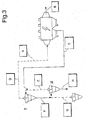
- Figure 3 schematically shows an apparatus according to the present invention comprising an electrofilter and a 3 stage cyclone suspension preheater.
- the path of the gaseous flow of the combustion fumes from the kiln (not shown) and of the raw meal to be preheated is such as to make three overall stages of preheating and relative separation of the preheated meal from the combustion fumes.
- the calculation of the temperatures of the gaseous flows and of the dust was carried out by repeatedly searching for the temperature values that bring the energy balances of each stage of the process into equilibrium.
- the mass balance was made by taking the amount of clinker produced, expressed in kg, as reference. This amount is less than that of the raw meal fed to the process to obtain the clinker (about 1.55 kg of raw meal is needed to produce 1 kg of clinker).
- Point A (meal): Amount: 1.55 kg/kg of clinker Temperature: 50°C Calorie content: 24 kcal/kg of clinker Point B (fumes): Amount: 1.5 Nm 3 /Kg of clinker Temperature: 308°C Calorie content: 166 kcal/kg of clinker Point C (meal): Amount: 1.65 kg/kg of clinker Temperature: 308°C Calorie content: 158 kcal/kg of clinker Point D (meal): Amount: 0.10 kg/kg clinker Temperature: 576°C Calorie content: 18 kcal/kg clinker Point D (fumes) : Amount: 1.4 Nm 3 /Kg of clinker Temperature: 576°C Calorie content: 282 kcal/kg of clinker Point E (metal) : Amount: Amount: 1.55 kg/kg of clinker Temperature: 50°C Calorie content: 24 k
- the energy balance of each of the 3 preheating stages is the following:
- the aforementioned values of the temperatures of the gaseous flows and of the dust show that the heat exchange able to be obtained with the apparatus according to the present invention is comparable to that of a 6 stage cyclone suspension preheater according to the state of the art.
- the calculations of the example indicate that in the apparatus according to the present invention the thermal equilibrium between the preheated raw meal and the combustion fumes at the outlet of the electrofilter is reached at a temperature of about 308°C. This value is comparable to that reached by the meal after 3-4 cyclone stages in a 6 stage preheater in a conventional clinker production plant.
- the possibility of using a suspension preheater having up to 3-4 fewer cyclone stages means a reduction in height of the support structure of the preheating apparatus of up to about 45-50 m, since the electrofilter is installed on the ground and the transportation of the dust from the electrofilter to the 3 stage cyclone preheater is carried out through a pneumatic or mechanical system (elevator).
- An apparatus according to the present invention comprising a 4 stage cyclone suspension preheater, an electrofilter and a NO x reduction system was tested.
- the purified combustion fumes exiting the electrofilter were subjected to a selective catalytic reduction treatment in a suitable SCR device.
- the selective catalytic reduction was carried out at a temperature of about 320°C, in the presence of NH3 as reducing agent (100-150 mg/Nm 3 , value referring to then anhydrous fumes and to 10% in volume of O 2 ). Ammonia was present in the combustion fumes, since it derives from the raw materials.
- the purified combustion fumes exiting the electrofilter and fed to the SCR device had a dust (meal) concentration of about 5 g/Nm 3 and a temperature of about 350°C.
- a dust (meal) concentration of about 5 g/Nm 3 and a temperature of about 350°C.
- SO 2 100-200 mg/NM 3 , value referring to the anhydrous fumes and to 10% in volume of O 2 ).
- the results show how the apparatus of the present invention is characterised by an excellent regularity of operation and by low energy consumption associated with the cleaning of the catalyst.
Landscapes
- Engineering & Computer Science (AREA)
- Chemical & Material Sciences (AREA)
- Environmental & Geological Engineering (AREA)
- Mechanical Engineering (AREA)
- General Engineering & Computer Science (AREA)
- Ceramic Engineering (AREA)
- Health & Medical Sciences (AREA)
- General Chemical & Material Sciences (AREA)
- Chemical Kinetics & Catalysis (AREA)
- Structural Engineering (AREA)
- Life Sciences & Earth Sciences (AREA)
- Organic Chemistry (AREA)
- Oil, Petroleum & Natural Gas (AREA)
- Materials Engineering (AREA)
- Analytical Chemistry (AREA)
- Biomedical Technology (AREA)
- Sustainable Development (AREA)
- Public Health (AREA)
- Environmental Sciences (AREA)
- Ecology (AREA)
- Biodiversity & Conservation Biology (AREA)
- Furnace Details (AREA)
- Curing Cements, Concrete, And Artificial Stone (AREA)
- Muffle Furnaces And Rotary Kilns (AREA)
- Waste-Gas Treatment And Other Accessory Devices For Furnaces (AREA)
- Other Resins Obtained By Reactions Not Involving Carbon-To-Carbon Unsaturated Bonds (AREA)
Description
- The present invention concerns an improved apparatus for the production of clinker from raw meal and the relative process. Cement is a hydraulic binder used to bind inert solid materials, like sand and gravel, thus forming concrete and mortar, i.e. the base components for building.
- On the industrial scale, cement is made through mixing and grinding of clinker and gypsum with corrective substances like lime, slag and pozzolana.
- In the process for producing cement according to what is known as "dry" technology, the clinker is obtained by high temperature baking of a mixture of raw materials consisting mainly of lime (calcium carbonate) and clay (silica, alumina, iron oxides, as well as crystallisation water). The raw materials are mixed in solid state in the desired proportions and then finely ground until a homogeneous powder known as "raw meal" is obtained. In the present description, by "raw meal" we thus mean the homogeneous dust thus obtained used as starting material for producing clinkers.
- The raw meal is transformed into a clinker by means of baking at a temperature of about 1450°C in a rotary kiln essentially consisting of an inclined rotary cylinder.
- During its transit in the rotary kiln, the raw meal is heated up to temperatures of about 1450°C. During heating the meal firstly undergoes complete calcining and, thereafter, reacts forming the calcium silicates and aluminates (clinkering reaction) that represent the main constituents of the clinker. More specifically, during the clinkering reaction there are a series of chemical reactions between calcium oxide, silicon oxide, aluminium oxide and iron oxide, said reactions being encouraged by the melting of a part of the raw materials themselves (aluminium and iron oxides).
- The energy necessary to make the clinkering reaction take place is produced by means of a burner positioned on the head of the rotary kiln, at the opposite end with respect to that in which the meal is loaded. The fuels generally used are coal, petcoke, fuel oil, methane, as well as alternative fuels like, for example, meat meals.
- The heat energy is transmitted to the raw meal subjected to treatment by irradiation in the baking area at the burner (temperature of about 2000°C) and by convection and conduction by means of the combustion gases in the remaining part of the kiln.
- At the end of the baking treatment, the clinker thus obtained is discharged from the rotary kiln and is quickly cooled in an air cooler in order to stabilise it.
- The processes according to the state of the art are represented and discussed with reference to the following figures:
-
Figure 1A , which shows a schematic representation of a clinker production plant according to the state of the art comprising a rotary kiln equipped with a 4 stage suspension preheater; -
Figure 1B , which shows a schematic representation of a clinker production plant according to the state of the art comprising a rotary kiln equipped with a 5 stage suspension preheater and a precalciner. - In the aforementioned figures the full lines indicate the flows of solid material, the dashed lines indicate the gaseous stream flows, whereas the Roman numerals indicate the stages of the suspension preheaters.
- In clinker production plants known in the state of the art, the raw meal, before being fed to the rotary kiln, is subjected to a preheating and, optionally, precalcining treatment.
- One of the currently most widely used preheating techniques is based on the use of the so-called "suspension preheater" or "multi-stage cyclone preheater" (hereafter also just "preheater"), consisting of a cyclone tower in which each preheating stage takes place in one or more cyclones. In such a type of preheater, by first cyclone we mean the cyclone in which the first preheating stage and the first separation between preheated meal and combustion fumes take place, by second cyclone we mean the cyclone in which the second preheating stage and the second separation between preheated meal and combustion fumes take place and the subsequent cyclones of the multi-stage cyclone preheater are analogously defined. In the present description, the first cyclone of the preheater, just like the subsequent cyclones, should always be interpreted according to the above definition.
- The first stage, unlike the subsequent ones, is configured to minimize the carrying of dust by the combustion fumes from the kiln. Despite this, the concentration of dust in the combustion fumes exiting the preheater stays high (around 50-100 g/Nm3).
- The preheating and precalcining steps are carried out, respectively, in the preheater 1 and in the precalciner 2 (
Figures 1A and 1B ). The presence of these steps allows the partially calcined (30-40%) meal that has been preheated to a temperature of about 950°C to be fed to therotary kiln 3, with a substantial energy saving in the subsequent clinkering reaction. - The presence of the preheating step, optionally accompanied by the precalcining step, also allows rotary kilns of reduced size to be used, thus reducing the heat losses that occur in such kilns and increasing the overall energy efficiency of the clinker production process.
- In the preheater, the starting raw meal is gradually brought from the temperature of about 40°C to about 950°C. The heating is carried out keeping the meal in suspension in a flow of hot gases, consisting of the combustion fumes of the rotary kiln, exploiting the large heat exchange surface between the meal and the combustion fumes.
- In the preheating step the amount of time for which the solid phase (meal) is in contact with the gaseous phase (combustion fumes of the rotary kiln) is of fundamental importance. In order to ensure an optimal contact time between the solid phase and the gaseous phase, the suspension preheater consists of a series of cyclones (from 4 to 6) arranged one on top of the other to form a tower of variable height even up to 130-150 m. Such a preheater can be defined as a multi-stage cyclone preheater. The first preheating stage, which occurs at the top of the tower, can be carried out in two cyclones in parallel to ensure better efficiency of separation of the meal from the gaseous flow before it exits the preheater.
- with reference to
Figure 1A , in the multi-stage cyclone preheater 1 the combustion fumes from therotary kiln 3 and having a temperature of about 900-1000°C pass through the cyclones from the bottom towards the top (from IV to I). The starting raw meal is mixed with the combustion fumes in the preheater 1, inside which it is inserted through an inlet 4, arranged at the top of the preheater, between the first (I) cyclone and the second (II) cyclone. The raw meal passes through the preheater up to the outlet in the lower part, transported from one cyclone to the next by the flow of combustion fumes. In each cyclone about 80% of the solid phase (meal) is separated from the gaseous phase (combustion fumes) to then be inserted once again in the gaseous phase entering into the cyclone below. The gaseous phase containing the remaining solid fraction (about 20% of the meal), on the other hand, flows to the next cyclone above. - At the bottom of the preheater 1, a preheated meal is obtained having a temperature of about 950°C. From the last preheating stage in the multi-stage cyclone preheater, the meal is discharged directly into the
rotary kiln 3 for the subsequent clinkering reaction. - In plants equipped with a precalciner 2 (
Figure 1B ), the preheated meal is fed from the preheater 1 to asuitable combustion chamber 5, equipped with aburner 6, inside which it undergoes a partial calcining process. The precalcined meal leaves theprecalciner 2 and is fed, together with the combustion fumes of theprecalciner 2, to the last stage (V) of the preheater 1 to then proceed towards therotary kiln 3. The combustion fumes of theprecalciner 2 flow together with those of therotary kiln 3 and climb the preheater 1 up to the top outlet 7, after the first cyclone. - The gaseous flow exiting through the outlet 7 of the preheater, comprising the combustion fumes of the
rotary kiln 3 and, optionally, those of theprecalciner 2, has a temperature of about 270-360°C. Before being released into the atmosphere, this flow is generally used in other steps of the cement production process (for example, for grinding and drying the raw materials or else as combustion air in the rotary kiln or in the precalciner) to recover the heat content. - The preparation of the clinker in a cement production plant like the one described above generates enormous volumes of gaseous emissions, which can potentially pollute the environment.
- The gaseous flow exiting the preheater is characterised by a high concentration of polluting substances, in particular nitrogen oxides (NOx) and dusts.
- The NOx derive mainly from the combustion processes that take place in the rotary kiln and, optionally, in the precalciner. The main techniques currently used to reduce the NOx in the gaseous flow exiting the preheater are the following two:
- Selective Non-Catalytic Reduction (SNCR) that foresees the reaction of the NOx with a reducing agent (for example ammonia or urea) in the high temperature area of the preheater;
- Selective Catalytic Reduction (SCR) that foresees the reaction of the NOx with NH3 as reducing agent in the presence of a catalyst.
- The SNCR technique is effective if used on a gaseous flow having a temperature of 800-900°C and allows most of the NOx present to be reduced (i.e. more than 50%).
- The application of the SCR technique, only recently used in the field of electrical energy production and in the development phase in the field of cement, allows very high reduction yields (over 90%) to be achieved. The SCR technique is effective if used on a gaseous flow having a temperature of between about 300 and 400°C.
- Considering this optimal temperature range, the SCR reduction system is installed in clinker production plants at the top outlet of the preheater, after the first cyclone, where the gaseous flow exiting through such an outlet, comprising the combustion fumes of the rotary kiln and, optionally, those of the precalciner, has a temperature of about 270-360°C.
- The application of SCR technology does, however, have various drawbacks due mainly to the presence of substantial quantities of dust in the combustion fumes exiting the preheater. The dust, depositing on the walls of the catalyst, reduce the efficiency of the SCR reduction system, at the same time increasing the resistance to the passage of the gaseous flow and therefore the energy consumption linked to moving it.
- The presence of dust in the treated gaseous effluent also means high energy consumption associated with the need to clean the catalyst with compressed air, as well as reducing the useful life of the catalyst due to the abrasive action that the dust exerts on the surface of the catalytic bed.
- The high presence of dust is linked essentially to the limited efficiency of dust removal of the cyclones that make up the preheater. Although they are designed to maximise the separation efficiency, the cyclones are only able to effectively separate heavier dust.
- Secondly, at the outlet of the preheater there can also be ashes generated by the combustion in the burners of the rotary kiln and of the precalciner of alternative fuels, like for example animal meals. The presence of ashes (containing phosphates) causes the catalyst to be poisoned and its NOx reduction effectiveness to consequently be decreased.
- Sometimes in the fumes there are sulphur oxides, mainly in the form of SO2, depending on the sulphur content of the raw materials used.
The SO2 reduction in these cases can be carried out by means of injection of calcium oxide- and/or calcium hydroxide-based compounds in the combustion fumes, with consequent formation of calcium sulphate, said calcium sulphate advantageously being able to be recycled in the clinker production process. The effectiveness of reduction of the sulphur oxides in gaseous phase according to the aforementioned technique is also limited by the presence in the fumes of high concentrations of dust, which make it almost impossible to recycle unreacted lime. - The combustion fumes exiting the preheater, after having been purified of NOx and SOx and after having optionally been recycled through other steps of the production process to recover its residual heat, must finally be removed of dust before being released into the atmosphere.
- The dust-removal process is normally carried out through filtering with electrofilters (also known as electrostatic precipitators) or else with fabric filters, the latter being most widely used in clinker production plants.
- Unlike electrofilters that can filter gaseous flows even at a high temperature, fabric filters can only operate at temperatures below 250°C (according to the type of fabric used). Therefore, the use of fabric filters to remove dust from the combustion fumes necessitates the installation of suitable systems for reducing the temperature of the gases to be filtered (for example, conditioning towers, heat exchangers, diluting air insertion) with a consequent increase in the investment costs and the energy consumption of the process.
- The preparation of clinker in a cement production plant like the one described above also has other drawbacks.
- The short contact time between the solid phase (meal) and the gaseous phase (combustion fumes) that can be made in a single stage of the suspension preheater necessitates the installation of many cyclones, making a multi-stage preheater, to reach an acceptable heat exchange level. This requires the construction of strong support structures of the preheater and, at the same time, high energy consumption associated with the transportation of the fumes and of the solid material through the preheater.
- According to the production capacity of the plant and the specific production technologies adopted, the preheater can reach considerable heights (130-150 m), also causing "landscape defacement".
- Moreover, even using 4-6 stage preheaters that allow extended contact times, the heat exchange between meal and combustion fumes is not sufficiently high to ensure that thermal equilibrium is reached. In preheaters known in the state of the art, the difference between the temperature of the meal and that of the combustion fumes exiting the preheater is on average about 40-50°C.
- An example of an apparatus according to the state of the art is disclosed in
EP 0341417 . In fact,EP0341417 discloses an apparatus for the production of clinker from raw meal, comprising: a rotary kiln; a multistage cyclone preheater connected downstream of said rotary kiln (8) in relation to the direction of flow of the fumes of a combustion taking place in said kiln; an electrofilter connected downstream of the said preheater and upstream of said electrofilter in relation to said direction of flow of the combustion fumes and in that it comprises a second inlet for the feeding of partially preheated raw meal from the electrofilter to the preheater. - The purpose of the present invention is to make an improved apparatus and process to overcome the highlighted drawbacks of the state of the art.
- A first object of the present invention is an apparatus for the production of clinker from raw meal, comprising
- a rotary kiln 8;
- a
multi-stage cyclone preheater 9 connected downstream of said rotary kiln 8 with respect to the direction of flow of thefumes 11 of a combustion taking place in said kiln 8; - an
electrofilter 10 connected downstream of saidpreheater 9 with respect to said direction of flow of the combustion fumes 11; characterised in that it comprises a first inlet 17 for feeding raw meal to said combustion fumes 11, said inlet 17 being arranged downstream of saidpreheater 9 and upstream of saidelectrofilter 10 with respect to said direction of flow of the combustion fumes 11, and in that it comprises asecond inlet 18 for feeding partially preheatedraw meal 14 from said electrofilter 10 to saidpreheater 9, said apparatus further comprising means for purifying the combustion fumes cleaned of dust exiting the electrofilter from further pollutants and means for recovering their heat, wherein the means for purifying the combustion fumes cleaned of dust exiting the electrofilter comprise NOx lowering means and/or a sulphur oxide lowering device, in particular SO2. - A second object of the present invention is an improved process for the production of clinker from raw meal in an apparatus comprising a rotary kiln 8, optionally a precalciner, a
multi-stage cyclone preheater 9 and anelectrofilter 10, said process comprising the following operating steps: - a) making the combustion fumes 11, from the rotary kiln 8, flow from the bottom towards the top in the
preheater 9; - b) mixing the
raw meal 22 with the combustion fumes 11 exiting thepreheater 9, with preheating of theraw meal 14 by contact with the combustion fumes 11, and formation of a gaseous flow containing a partially preheatedraw meal 14 in suspension; - c) feeding the flow obtained in step b) to the
electrofilter 10 and separating the partially preheatedraw meal 14 from a flow of combustion fumes 15 free from dust; - d) feeding the partially preheated
raw meal 14 obtained in step c) to thepreheater 9 and preheating theraw meal 14 by contact in countercurrent with the combustion fumes 11 that flow from the bottom towards the top; - e) feeding the preheated
raw meal 16 from step d) to the rotary kiln 8 for the subsequent production of clinker; - f) submitting the combustion fumes cleaned of dust (15) exiting the electrofilter (10) to further pollutant purification treatments and heat recovery treatments, wherein phase f) comprises a NOx lowering treatment and/or a sulphur oxide lowering treatment, in particular SO2.
- A preferred embodiment of the apparatus and of the process according to the present invention is schematically represented in the attached
Figures 2 and3 . - Also in
Figures 2 and3 , the solid lines indicate the flows of solid material, the broken lines indicate the gaseous flows, whereas the Roman numerals indicate the cyclones of the suspension preheater. - Step a) of the process according to the present invention foresees making the combustion fumes 11, from the rotary kiln 8, flow from the bottom towards the top in the
preheater 9. Similarly to what occurs in a clinker production plant according to the prior art, the combustion fumes 11 go into thepreheater 9 at the bottom and climb up the cyclones of themulti-stage cyclone preheater 9 up to theupper outlet 12. - In step b) of the process, the starting
raw meal 22 is mixed with the combustion fumes 11 exiting thepreheater 9, with preheating of theraw meal 14 by contact with the combustion fumes 11, and formation of a gaseous flow containing a partially preheatedraw meal 14 in suspension. - The insertion of the starting
raw meal 22 into the combustion fumes 11 takes place through a suitable inlet 17 arranged downstream of theoutlet 12 from thesuspension preheater 9 and upstream of theinlet 13 into theelectrofilter 10, with respect to the direction of flow of the combustion fumes 11. In this way, theraw meal 22 mixes with the combustion fumes 11 remaining in suspension in the gaseous phase and, at the same time, heating up, thus forming a gaseous flow containing the partially preheatedraw meal 14 in suspension.
The temperature of the partially preheatedraw meal 14 depends, as well as upon the temperature of the combustion fumes 11 exiting theoutlet 12 of thepreheater 9, also upon the length of the path that connects the inlet 17 of theraw meal 22 into the combustion fumes 11 to theinlet 13 into theelectrofilter 10 of the partially preheatedraw meal 14 in suspension (hereafter, more simply "path P"). Indeed, the contact time between theraw meal 22 and the combustion fumes 11 and, therefore, the extent of the heat exchange between the combustion fumes 11 and theraw meal 22 depend upon the length of said path P. By suitably selecting the length of the path P it is thus possible to vary the temperature of the partially preheatedraw meal 14 entering into thepreheater 9. In a preferred embodiment of the present invention, the length of said path P is such that the partially heatedraw meal 14 entering into thepreheater 9 has a temperature within the range 250-400°C, preferably 270-360°C. In clinker production plants known in the state of the art, the raw meal subjected to preheating in a suspension preheater has a temperature of about 40°C and reaches temperature values within the range 270-360°C after having passed through at least the first two preheating stages. The use of the electrofilter connected to a suspension preheater in accordance with the present invention thus allows the suspension preheater to be fed with a raw meal at a much higher temperature. Consequently, in order to complete the preheating of the raw meal up to the entry temperature into the rotary kiln (about 950°C) it is possible to use a suspension preheater having a smaller number of cyclone stages. Moreover, the apparatus according to the present invention is also much shorter than suspension preheaters used in clinker production plants since it has 1 or 2 less cyclones stages. - In the subsequent step c) the gaseous flow obtained in step b) is fed to the
electrofilter 10 where the partially preheatedraw meal 14 is separated from a flow of combustion fumes free fromdust 15. Such a separation takes place by electrostatic precipitation inside theelectrofilter 10. The partially preheatedraw meal 14 thus separated is fed to thepreheater 9, where it is mixed with the combustion fumes 11 that flow inside the preheater itself (step d)) and preheated by contact in countercurrent with the combustion fumes 11 that flow from the bottom towards the top. For this purpose, the partially preheatedraw meal 14 separated by means of theelectrofilter 10 is inserted into thepreheater 9 through aninlet 18 to thepreheater 9. Such aninlet 18 can preferably be foreseen at an intermediate point between two cyclones, preferably between the first and the second cyclone. - By connecting the
electrofilter 10 to thepreheater 9 in the aforementioned way, it is possible to use theelectrofilter 10 instead of one or more cyclones, also exploiting the better dust-removal efficiency of this kind of device with respect to cyclones. - In the final step of the process according to the present invention (step e)) the preheated raw meal 14 (at a temperature of about 950°C) is discharged from the bottom of the
preheater 9 into the rotary kiln 8 for the subsequent clinkering reaction. - The process according to the present invention also comprises a step f) consisting of subjecting the purified combustion fumes 15 exiting the
electrofilter 10 to further purification treatments of the pollutants and heat recovery treatments. - In the preferred embodiment of the process according to the present invention illustrated in
Figure 2 , the combustion fumes cleaned ofdust 15 obtained by separation of the partially preheatedraw meal 14 in step c) leave theelectrofilter 10 through theoutlet 19 to then be fed to further treatment stages to purify it of the pollutants and to recover its heat. For this purpose, the apparatus object of the present invention foresees suitable pollutant purification treatment means and heat recovery means. - The combustion fumes cleaned of
dust 15 can also be recycled to other steps of the clinker production process and, more generally, of the cement production process within which the clinker production apparatus according to the present invention is included. - A pollutant purification treatment to which the combustion fumes cleaned of
dust 15 can be sent is a NOx reduction process. Preferably, this treatment is a selective catalytic reduction process (SCR) by means of reducing agents (for example ammonia). The SCR process can be carried out through a suitable selective catalytic reduction device, like for example an SCR device (Figure 2 ), according to the ways known in the state of the art. The reducing agent can be fed in the gaseous flow upstream of the SCR device. Alternatively, the ammonia possibly present in the same flow of combustion fumes subjected to the SCR treatment can also be used as reducing agent. This ammonia derives from the heat treatment of the raw materials fed to the preheater and is transported by the combustion fumes through the electrofilter up to the catalyst of the SCR device. If the amount of ammonia deriving from the raw materials is insufficient, it is possible to feed an additional amount of ammonia or another reducing agent into the gaseous flow subjected to SCR. - Another purification treatment to which it is possible to subject the combustion fumes cleaned of
dust 15 is a sulphur oxide reduction process (desulphurisation), in particular for reducing SO2. Preferably, this process foresees the injection of calcium oxide- and/or calcium hydroxide-based compounds into the combustion fumes cleaned ofdust 15, through a suitable injection device. The aforementioned desulphuring process (not shown inFigure 2 ) can be carried out without distinction before or after the NOx reduction process. - The combustion fumes cleaned of
dust 15 can also be fed to other steps of the clinker production process and, more generally, to other steps of the cement production process (for example, in the grinding and drying of the raw materials or else as combustion air in the rotary kiln and/or in the precalciner) to recover its residual heat before it is released into the atmosphere. - The residual heat of the combustion fumes cleaned of
dust 15 is recovered using suitable heat recovery means. For this purpose, the apparatus according to the present invention can, for example, comprise a heat exchanger of the air/air, air/diathermal oil, air/water-steam type or else a water conditioning tower (conditioning tower 21 inFigure 2 ). - The process according to the present invention can also be applied in clinker production plants equipped with a precalciner. In this case, the combustion fumes of the rotary kiln are fed to the precalciner and from here, together with the combustion fumes of the precalciner, to the
suspension preheater 9. - The apparatus according to the present invention and the relative process have various advantages with respect to the processes and apparatuses known in the state of the art.
- In accordance with the present invention, the electrofilter is used in the clinker production process as an integral part of the production process, in particular as an integral part of the preheating apparatus. In the processes of the prior art the electrofilter is, instead, used just as a dust-removal device from gaseous flows before being released into the atmosphere.
- The main advantages of the present invention are the following:
- the use of the electrofilter in combination with the suspension preheater allows the contact time between the raw meal and the combustion fumes during the preheating step to be increased, with a consequent improvement of the heat exchange and, therefore, of the thermal efficiency of the clinker production plant. Thanks to such an increase in thermal efficiency it is possible to eliminate one or more cyclones of the preheater (as schematically represented in
Figure 2 , where thepreheater 9 foresees just three cyclones), with a consequent reduction in height of the relative support structure, in investment costs and in environmental impact; - the combustion fumes exiting the electrofilter are characterised by low dust content. This makes it possible to improve the reduction efficiency of the subsequent purification steps by reduction of the NOx and SOx;
- in the case of use of a heat exchanger for recovery of the residual heat energy of the combustion fumes exiting the electrofilter, the low dust content reduces the typical problems of dirtying of the exchangers.
- With regard to the removal of NOx through SCR reduction systems, the plant and process according to the present invention allow combustion fumes with a low dust content to be subjected to SCR treatment with a consequent:
- increase in reliability of operation of the catalyst, decrease in load losses (due to clogging of the catalyst) and therefore in energy consumption for the transportation of the gases;
- decrease in energy consumption associated with the use of compressed air during the SCR treatment to maintain a sufficient degree of cleanliness of the catalyst;
- decrease in maintenance interventions of the SCR system due to clogging of the catalyst, poisoning, etc.;
- possibility of using a smaller amount of catalyst, thus reducing the bulk and the costs of the SCR system;
- extension of the useful life of the catalyst.
- Moreover, the present invention, allowing to overcome the problems of operation of the SCR reduction system connected with the high degree of dustiness of the combustion fumes, also allows the same reduction system to also be used to eliminate other types of polluting substances possibly present in the combustion fumes. For this purpose, indeed, it is sufficient to use, as well as the catalyst for the NOx, an additional catalyst of suitable chemical composition.
- Moreover, in the case in which alternative fuels are used in the clinker production process, the electrofilter ensures the reduction of the possible ashes produced (typically containing phosphates) that can cause the catalyst to be poisoned. A further advantage of the present invention is, therefore, to make the use of SCR technology compatible with any type of alternative fuels.
- The following example embodiments are provided merely to illustrate the present invention and they should not be taken to limit the scope of protection defined by the attached claims.
-
Figure 3 schematically shows an apparatus according to the present invention comprising an electrofilter and a 3 stage cyclone suspension preheater. In said apparatus the path of the gaseous flow of the combustion fumes from the kiln (not shown) and of the raw meal to be preheated is such as to make three overall stages of preheating and relative separation of the preheated meal from the combustion fumes. - In order to demonstrate the high energy efficiency of the process and of the apparatus according to the present invention, the temperature of the gaseous flow (combustion fumes) and of the dust (meal) has been calculated in different points of the apparatus. For this purpose the following assumptions have been made:
- the gaseous flow and the dust exiting the cyclones and the electrofilter are in thermal equilibrium;
- the concentration of dust in the gaseous flows exiting the cyclones and the electrofilter are negligible, i.e. the separation efficiency is close to 100%.
- The calculation of the temperatures of the gaseous flows and of the dust was carried out by repeatedly searching for the temperature values that bring the energy balances of each stage of the process into equilibrium.
- The mass balance was made by taking the amount of clinker produced, expressed in kg, as reference. This amount is less than that of the raw meal fed to the process to obtain the clinker (about 1.55 kg of raw meal is needed to produce 1 kg of clinker).
- From the calculations carried out, in points A-H of the apparatus the combustion fumes and the meal have the following characteristics:
Point A (meal): Amount: 1.55 kg/kg of clinker Temperature: 50°C Calorie content: 24 kcal/kg of clinker Point B (fumes): Amount: 1.5 Nm3/Kg of clinker Temperature: 308°C Calorie content: 166 kcal/kg of clinker Point C (meal): Amount: 1.65 kg/kg of clinker Temperature: 308°C Calorie content: 158 kcal/kg of clinker Point D (meal): Amount: 0.10 kg/kg clinker Temperature: 576°C Calorie content: 18 kcal/kg clinker Point D (fumes) : Amount: 1.4 Nm3/Kg of clinker Temperature: 576°C Calorie content: 282 kcal/kg of clinker Point E (metal) : Amount: 0.10 kg/kg of clinker Temperature: 826°C Calorie content: 26 kcal/kg of clinker Point E (fumes): Amount: 1.3 Nm3/Kg of clinker Temperature: 826°C Calorie content: 386 kcal/kg of clinker Point F (meal): Amount: 1.65 kg/kg of clinker Temperature: 526°C Calorie content: 270 kcal/kg of clinker Point G (meal): Amount: 0.10 kg/kg of clinker Temperature: 860°C Calorie content: 27 kcal/kg of clinker Point G (fumes): Amount: 1.2 Nm3/Kg of clinker Temperature: 860°C Calorie content: 372 kcal/kg of clinker - The energy balance of each of the 3 preheating stages is the following:
- Input flow (kcal/kg of meal treated): 282 (Point D, fumes) + 18 (Point D, meal) + 24 (Point A, meal) = 324. Output flow (kcal/kg of meal treated): 166 (Point B, fumes) + 158 (Point C, meal) = 324.
- Input flow (kcal/kg of meal treated): 386 (Point E, fumes) + 26 (Point E, meal) + 158 (Point C, meal) = 570. Output flow (kcal/kg of meal treated): 282 (Point D, fumes) + 18 (Point D, meal) + 270 (Point F, meal) = 570.
- Input flow (kcal/kg of meal treated): 270 (Point F, meal) + 372 (Point G, fumes) + 27 (Point G, meal) = 669. Output flow (kcal/kg of meal treated): 386 (Point E, fumes) + 26 (Point E, meal) + 256 (Point H, meal) = 668.
- The difference between the value of the input flow and the output flow (1 kcal/kg of clinker) that is observed in the third stage is due to the approximation of the calculation.
- The aforementioned values of the temperatures of the gaseous flows and of the dust show that the heat exchange able to be obtained with the apparatus according to the present invention is comparable to that of a 6 stage cyclone suspension preheater according to the state of the art. In particular, the calculations of the example indicate that in the apparatus according to the present invention the thermal equilibrium between the preheated raw meal and the combustion fumes at the outlet of the electrofilter is reached at a temperature of about 308°C. This value is comparable to that reached by the meal after 3-4 cyclone stages in a 6 stage preheater in a conventional clinker production plant. The possibility of using a suspension preheater having up to 3-4 fewer cyclone stages means a reduction in height of the support structure of the preheating apparatus of up to about 45-50 m, since the electrofilter is installed on the ground and the transportation of the dust from the electrofilter to the 3 stage cyclone preheater is carried out through a pneumatic or mechanical system (elevator).
- An apparatus according to the present invention comprising a 4 stage cyclone suspension preheater, an electrofilter and a NOx reduction system was tested.
- The purified combustion fumes exiting the electrofilter were subjected to a selective catalytic reduction treatment in a suitable SCR device. The selective catalytic reduction was carried out at a temperature of about 320°C, in the presence of NH3 as reducing agent (100-150 mg/Nm3, value referring to then anhydrous fumes and to 10% in volume of O2). Ammonia was present in the combustion fumes, since it derives from the raw materials.
- The purified combustion fumes exiting the electrofilter and fed to the SCR device had a dust (meal) concentration of about 5 g/Nm3 and a temperature of about 350°C. In the combustion fumes there was also a high concentration of SO2 (100-200 mg/NM3, value referring to the anhydrous fumes and to 10% in volume of O2).
- In the testing the NOx reduction efficiency, the electrical energy consumption for the cleaning with compressed air of the catalyst, the load losses caused by the clogging of the catalyst, how long the catalyst lasts and the occurrence of operating problems of the rotary kiln were evaluated.
- The results obtained in the testing of the aforementioned apparatus (indicated in table 1 as "Apparatus present invention") are shown in the subsequent table 1 together with the data relative to an SCR treatment of combustion fumes from a clinker production plant of the conventional type (indicated in table 1 as "Conventional apparatus"). In the conventional apparatus the combustion fumes subjected to SCR treatment came from a 5 stage cyclone suspension preheater and they had a temperature of about 310°C. The concentration of dust in the fumes treated in the SCR system was greater than 70 g/Nm3. In the combustion fumes of the conventional apparatus there were also small concentrations of NH3 and SO2 deriving from the raw materials. Further NH3 was then added to the treated gaseous flow to drive the SCR process in conditions as close as possible to those of the apparatus according to the present invention.
Table 1 Parameter Unit Apparatus present invention Conventional apparatus Temperature °C 320 310 NOx reduction efficiency % 99 >90 cleaning system kWh/tclicker 0,2 (discontinuous) 2 (continuous) Life of the catalyst --- >5 years 3-5 years Interruptions in operation of the rotary kiln --- None Frequent Load losses --- As designed Progressively increasing due to clogging of the catalytic bed - The results of table 1 demonstrate how the apparatus and the process object of the present invention allow the effectiveness of the SCR treatment system to also be improved with respect to an analogous treatment inserted in a conventional clinker production plant.
- The results also show how the apparatus of the present invention is characterised by an excellent regularity of operation and by low energy consumption associated with the cleaning of the catalyst.
- Finally, it is worth noting that a modest dust removal of the combustion fumes by means of the electrofilter (up to concentrations of the order of a gram) is sufficient to obtain a substantial increase in efficiency of the SCR device.
Claims (13)
- Apparatus for the production of clinker from raw meal, comprising- a rotary kiln (8);- a multistage cyclone preheater (9) connected downstream of said rotary kiln (8) in relation to the direction of flow of the fumes (11) of a combustion taking place in said kiln (8);- an electrofilter (10) connected downstream of said preheater (9) in relation to said direction of flow of the combustion fumes (11);characterised in that it comprises a first inlet (17) for the feeding of raw meal to said combustion fumes (11), said inlet (17) being placed downstream of said preheater (9) and upstream of said electrofilter (10) in relation to said direction of flow of the combustion fumes (11), and in that it comprises a second inlet (18) for the feeding of partially preheated raw meal (14) from said electrofilter (10) to said preheater (9), said apparatus further comprising means for purifying the combustion fumes cleaned of dust exiting the electrofilter from further pollutants and means for recovering their heat, wherein the means for purifying the combustion fumes cleaned of dust exiting the electrofilter comprise NOx lowering means and/or a sulphur oxide lowering device, in particular SO2.
- Apparatus according to claim 1 further comprising a precalcinator.
- Apparatus according to claim 1, wherein the NOx lowering means are a selective catalytic reduction device operating with reducing additives.
- Apparatus according to one of claims 1-3 wherein the sulphur oxide lowering device, in particular SO2, is a device for the injection in the combustion fumes cleaned of dust of calcium oxide- and/or calcium hydroxide-based compounds.
- Apparatus according to one or more of claims from 1 to 4 wherein the means for recovering the heat contained in the combustion fumes comprise a heat exchanger and/or a conditioning tower.
- Apparatus according to one or more of claims from 1 to 5, wherein the second inlet (18) is provided in an intermediate point between two cyclones, preferably between the first and second cyclones.
- Apparatus according to one or more of claims from 1 to 6, wherein the length of the path that connects the inlet (17) of the raw meal (22) in the combustion fumes (11) to the inlet (13) in the electrofilter (10) of the partially preheated raw meal (14) in suspension is such that the partially preheated raw meal (14) entering the preheater (9) has a temperature comprised in the 250-400°C range, preferably 270-360°C.
- Improved process for the production of clinker from raw meal in an apparatus comprising a rotary kiln (8), optionally a precalcinator, a multistage cyclone preheater (9) and an electrofilter (10), said process comprising the following operating steps:a) making the combustion fumes (11), from the rotary kiln (8), flow from bottom to top into the preheater (9);b) mixing the raw meal (22) with the combustion fumes (11) exiting the preheater (9), with preheating of the raw meal (14) by contact with the combustion fumes (11), and formation of a gas flow containing a partially preheated raw meal (14) in suspension;c) feeding the flow obtained in phase b) to the electrofilter (10) and separating the partially preheated raw meal (14) from a flow of combustion fumes cleaned of dust (15);d) feeding the partially preheated raw meal (14) obtained in step c) to the preheater (9) and preheating the raw meal (14) by contact in counter-flow with the combustion fumes (11) that flow from bottom to top;e) feeding the preheated raw meal (16) from phase d) to the rotary kiln (8) for the subsequent production of clinker,f) submitting the combustion fumes cleaned of dust (15) exiting the electrofilter (10) to further pollutant purification treatments and heat recovery treatments, wherein phase f) comprises a NOx lowering treatment and/or a sulphur oxide lowering treatment, in particular SO2.
- Process according to claim 8 wherein the partially preheated raw meal (14) which is fed to the preheater (9) in step d) has a temperature comprised in the 250-400°C range.
- Process according to claim 9, wherein the partially preheated raw meal (14) which is fed to the preheater (9) in step d) has a temperature comprised in the 270-360°C range.
- Process according to one of claims 8-10, wherein the NOx lowering treatment is a selective catalytic reduction process.
- Process according to one of claims 8-11, wherein the sulphur oxide lowering treatment is made by means of injection in the combustion fumes cleaned of dust (15) of calcium oxide- and/or calcium hydroxide-based compounds
- Process according to one or more of claims from 10 to 12 wherein step f) comprises a recovery treatment of the heat contained in the combustion fumes cleaned of dust (15) by means of at least one heat exchanger and/or one conditioning tower (21).
Applications Claiming Priority (2)
| Application Number | Priority Date | Filing Date | Title |
|---|---|---|---|
| ITMI2008A002311A IT1391447B1 (en) | 2008-12-23 | 2008-12-23 | IMPROVED APPARATUS FOR CLINKER PRODUCTION STARTING FROM RAW FLOUR AND ITS PROCESS |
| PCT/IB2009/007822 WO2010073090A1 (en) | 2008-12-23 | 2009-12-17 | Improved apparatus for the production of clinker from raw meal and relative process |
Publications (2)
| Publication Number | Publication Date |
|---|---|
| EP2376857A1 EP2376857A1 (en) | 2011-10-19 |
| EP2376857B1 true EP2376857B1 (en) | 2016-09-07 |
Family
ID=41227363
Family Applications (1)
| Application Number | Title | Priority Date | Filing Date |
|---|---|---|---|
| EP09810784.0A Not-in-force EP2376857B1 (en) | 2008-12-23 | 2009-12-17 | Improved apparatus for the production of clinker from raw meal and relative process |
Country Status (13)
| Country | Link |
|---|---|
| US (1) | US8784097B2 (en) |
| EP (1) | EP2376857B1 (en) |
| CN (1) | CN102317730A (en) |
| CA (1) | CA2747944C (en) |
| DK (1) | DK2376857T3 (en) |
| EG (1) | EG26716A (en) |
| ES (1) | ES2605437T3 (en) |
| IT (1) | IT1391447B1 (en) |
| MA (1) | MA32991B1 (en) |
| PL (1) | PL2376857T3 (en) |
| PT (1) | PT2376857T (en) |
| RU (1) | RU2504722C2 (en) |
| WO (1) | WO2010073090A1 (en) |
Families Citing this family (14)
| Publication number | Priority date | Publication date | Assignee | Title |
|---|---|---|---|---|
| DE102009022903A1 (en) * | 2009-05-27 | 2010-12-09 | Polysius Ag | Process and plant for the heat treatment of fine-grained material |
| DE102010060104B4 (en) | 2010-10-21 | 2014-02-06 | Elex Cemcat Ag | Flue gas purification stage and cement manufacturing plant having these |
| ITMI20120269A1 (en) * | 2012-02-23 | 2013-08-24 | Italcementi Spa | INTEGRATED APPARATUS FOR CLINKER PRODUCTION STARTING FROM RAW FLOUR |
| CN103120898A (en) * | 2012-12-28 | 2013-05-29 | 江苏科行环境工程技术有限公司 | Process device for reducing selective catalytic reduction (SCR) catalyst poisoning |
| AT515421B1 (en) * | 2014-02-25 | 2015-09-15 | Holcim Technology Ltd | Apparatus for preheating cement raw meal for cement clinker production |
| DE102014005508B4 (en) * | 2014-04-12 | 2017-12-21 | Khd Humboldt Wedag Gmbh | Process and plant for denitrification of flue gases with SNCR (Selective non-catalytic reduction) and downstream catalyst for ammonia degradation |
| CN106731645A (en) * | 2017-03-09 | 2017-05-31 | 徐州贝克福尔节能环保技术有限公司 | The facility and method of a kind of preheater inside self-loopa desulfurization |
| CN108686476A (en) * | 2018-07-13 | 2018-10-23 | 天津水泥工业设计研究院有限公司 | A kind of cement industry dedusting denitrating technique, equipment and its remodeling method |
| CN111450692A (en) * | 2020-05-26 | 2020-07-28 | 张亚莉 | Cement rotary kiln tail gas sulfur dioxide ultralow emission treatment device and process |
| FR3136275B1 (en) * | 2022-06-06 | 2024-06-21 | Solaronics | Drying plant |
| CN116099352A (en) * | 2022-12-02 | 2023-05-12 | 肖寒卫 | A flue gas low-dust SCR denitrification, desulfurization and material delivery system and method |
| CN116659235A (en) * | 2023-06-01 | 2023-08-29 | 武汉建筑材料工业设计研究院有限公司 | A Red Mud Reduction Roasting System |
| CN116765106B (en) * | 2023-06-21 | 2026-03-06 | 北京金隅红树林环保技术有限责任公司 | A method for large-scale remediation of contaminated soil using a rotary kiln |
| CN118846969B (en) * | 2024-07-03 | 2025-09-09 | 天津水泥工业设计研究院有限公司 | System and method for preparing high-activity SCM material from low-carbon raw material |
Family Cites Families (18)
| Publication number | Priority date | Publication date | Assignee | Title |
|---|---|---|---|---|
| DK142311B (en) * | 1973-01-05 | 1980-10-13 | Niro Atomizer As | Process for producing cement clinker of raw sludge and plant for carrying out the process. |
| DE3029210C2 (en) * | 1980-08-01 | 1984-09-27 | BKMI Industrieanlagen GmbH, 8000 München | Method of burning carbonate flours |
| DE3439129A1 (en) * | 1984-10-25 | 1986-05-07 | Krupp Polysius Ag, 4720 Beckum | METHOD AND INSTALLATION FOR THE HEAT TREATMENT OF FINE GRAIN GOODS |
| DE3817356A1 (en) * | 1988-01-18 | 1989-07-27 | Krupp Polysius Ag | Process and apparatus for the heat treatment of fine-grained material |
| DE3815763A1 (en) * | 1988-05-09 | 1989-11-23 | Kloeckner Humboldt Deutz Ag | METHOD AND SYSTEM FOR DRYING DAMP MATERIALS, SUCH AS CEMENT RAW MATERIALS BY MEANS OF A GAS FLOW |
| DE3905454A1 (en) * | 1989-02-22 | 1990-08-23 | Krupp Polysius Ag | Process and plant for heat-treating fine-grained material |
| DE4436939A1 (en) * | 1994-10-15 | 1996-04-18 | Kloeckner Humboldt Deutz Ag | Plant for the thermal treatment of flour-like raw materials |
| DE19649663C1 (en) * | 1996-11-29 | 1998-04-02 | Schwenk Baustoffwerke Kg E | Sulphur di:oxide removal from cement-making plant off-gases |
| DK0882687T3 (en) * | 1997-06-02 | 2000-07-31 | Doumet Joseph E Dipl Ing | Method and apparatus for making cement articles |
| TW487689B (en) * | 2000-03-30 | 2002-05-21 | Smidth & Co As F L | Method and apparatus for manufacturing cement clinker from particulate cement raw material |
| FR2817487B1 (en) * | 2000-12-04 | 2003-02-21 | Lab Sa | PROCESS AND PLANT FOR PURIFYING CEMENT SMOKE |
| DE10158968B4 (en) * | 2001-11-30 | 2010-01-14 | Khd Humboldt Wedag Gmbh | Method for reducing the emission of pollutants Dioxins and / or furans in a cement clinker production line |
| BR0315036B1 (en) * | 2002-10-02 | 2012-09-04 | method and plant for the manufacture of cement clinker. | |
| CN1512127A (en) * | 2002-12-31 | 2004-07-14 | 泰安新星粉体热学工程研究所有限公司 | Tail gas treating system for cement rotary kiln |
| DE102004003068A1 (en) * | 2004-01-21 | 2005-08-11 | Khd Humboldt Wedag Ag | Cement clinker production with partial flow deduction of polluted rotary kiln exhaust gas |
| CN100439846C (en) * | 2004-12-10 | 2008-12-03 | 贵阳铝镁设计研究院 | Method and equipment for utilizing waste heat of rotary kiln flue gas |
| GR1006855B (en) * | 2005-01-14 | 2010-07-06 | Σοφια Μπεθανη | Construction materials using aggregates from solid wastes |
| CN100998947B (en) * | 2006-12-30 | 2010-08-11 | 东北大学 | Magnesium oxide-based catalyst-adsorbent for flue gas denitrification and preparation method thereof |
-
2008
- 2008-12-23 IT ITMI2008A002311A patent/IT1391447B1/en active
-
2009
- 2009-12-17 PL PL09810784T patent/PL2376857T3/en unknown
- 2009-12-17 US US12/998,974 patent/US8784097B2/en not_active Expired - Fee Related
- 2009-12-17 EP EP09810784.0A patent/EP2376857B1/en not_active Not-in-force
- 2009-12-17 CN CN2009801565196A patent/CN102317730A/en active Pending
- 2009-12-17 PT PT98107840T patent/PT2376857T/en unknown
- 2009-12-17 MA MA34046A patent/MA32991B1/en unknown
- 2009-12-17 RU RU2011127332/02A patent/RU2504722C2/en not_active IP Right Cessation
- 2009-12-17 ES ES09810784.0T patent/ES2605437T3/en active Active
- 2009-12-17 CA CA2747944A patent/CA2747944C/en not_active Expired - Fee Related
- 2009-12-17 DK DK09810784.0T patent/DK2376857T3/en active
- 2009-12-17 WO PCT/IB2009/007822 patent/WO2010073090A1/en not_active Ceased
-
2011
- 2011-06-22 EG EG2011061075A patent/EG26716A/en active
Also Published As
| Publication number | Publication date |
|---|---|
| US20110311931A1 (en) | 2011-12-22 |
| MA32991B1 (en) | 2012-01-02 |
| CA2747944C (en) | 2015-06-16 |
| EG26716A (en) | 2014-06-15 |
| IT1391447B1 (en) | 2011-12-23 |
| US8784097B2 (en) | 2014-07-22 |
| CN102317730A (en) | 2012-01-11 |
| ES2605437T3 (en) | 2017-03-14 |
| RU2504722C2 (en) | 2014-01-20 |
| WO2010073090A1 (en) | 2010-07-01 |
| RU2011127332A (en) | 2013-01-27 |
| EP2376857A1 (en) | 2011-10-19 |
| CA2747944A1 (en) | 2010-07-01 |
| PL2376857T3 (en) | 2017-02-28 |
| PT2376857T (en) | 2016-12-15 |
| ITMI20082311A1 (en) | 2010-06-24 |
| DK2376857T3 (en) | 2017-01-02 |
Similar Documents
| Publication | Publication Date | Title |
|---|---|---|
| US8784097B2 (en) | Apparatus for the production of clinker from raw meal and relative process | |
| EP2379468B1 (en) | Process for purifying a flow of combustion fumes from a clinker production plant and relative apparatus | |
| CN101343047B (en) | Improved preparation technique for preparing sulphuric acid and cement with gypsum | |
| CN111233356B (en) | A method and system for preparing sulfoaluminate cement from all solid waste pretreated with aluminum ash | |
| CN102803176A (en) | Industrial method for producing a clinker having a high belite content | |
| US20180050303A1 (en) | Treatment of exhaust gases from cement clinker production | |
| EP4259590B1 (en) | Method of producing a synthetic carbonated mineral component in a cement manufacturing plant | |
| DK2694902T3 (en) | Process and plant for the production of cement clinker and for the purification of the resulting combustion gases (waste gases) | |
| CN115140957A (en) | Preheating and predecomposition method and device for co-production of cement by using efficient phosphogypsum to prepare acid | |
| JPS6321243A (en) | Manufacture of cement clinker and so2-containing exhaust gas | |
| WO2002018270A1 (en) | A method of decomposing gypsum to sulfur dioxide and the apparatus thereof | |
| EP3299080B1 (en) | Method for controlling ammonia content in cement flue gas and cement plant with controlled ammonia emission | |
| EP2817577A1 (en) | Integrated apparatus for the production of clinker from raw meal | |
| EP0152682B1 (en) | Denitration method and device for burning equipment using coal | |
| RU2520739C2 (en) | Production of high-strength high-early-strength alite portland cement and production line to this end | |
| HK1164431A (en) | Improved apparatus for the production of clinker from raw meal and relative process | |
| RU2547195C1 (en) | Production of portland cement clinker (versions) | |
| HK1162016A (en) | Process for purifying a flow of combustion fumes from a clinker production plant and relative apparatus | |
| RU2566159C1 (en) | Method of obtaining of low-temperature portland cement clinker | |
| CN106277863A (en) | A kind of processing method of desulfurated plaster | |
| CN1125159A (en) | Method for removing nitrogen monoxide and nitrogen dioxide mixture from waste gas of industrial kiln and furnace | |
| Sanders et al. | NOX Control Technologies for the Cement Industry | |
| PL191257B1 (en) | Cement clinker producing method | |
| BG111368A (en) | Device for producing clinker from raw flour containing a pre-heater with restricted height |
Legal Events
| Date | Code | Title | Description |
|---|---|---|---|
| PUAI | Public reference made under article 153(3) epc to a published international application that has entered the european phase |
Free format text: ORIGINAL CODE: 0009012 |
|
| 17P | Request for examination filed |
Effective date: 20110621 |
|
| AK | Designated contracting states |
Kind code of ref document: A1 Designated state(s): AT BE BG CH CY CZ DE DK EE ES FI FR GB GR HR HU IE IS IT LI LT LU LV MC MK MT NL NO PL PT RO SE SI SK SM TR |
|
| DAX | Request for extension of the european patent (deleted) | ||
| 17Q | First examination report despatched |
Effective date: 20160204 |
|
| GRAP | Despatch of communication of intention to grant a patent |
Free format text: ORIGINAL CODE: EPIDOSNIGR1 |
|
| INTG | Intention to grant announced |
Effective date: 20160419 |
|
| GRAS | Grant fee paid |
Free format text: ORIGINAL CODE: EPIDOSNIGR3 |
|
| GRAA | (expected) grant |
Free format text: ORIGINAL CODE: 0009210 |
|
| AK | Designated contracting states |
Kind code of ref document: B1 Designated state(s): AT BE BG CH CY CZ DE DK EE ES FI FR GB GR HR HU IE IS IT LI LT LU LV MC MK MT NL NO PL PT RO SE SI SK SM TR |
|
| REG | Reference to a national code |
Ref country code: GB Ref legal event code: FG4D |
|
| REG | Reference to a national code |
Ref country code: CH Ref legal event code: EP |
|
| REG | Reference to a national code |
Ref country code: IE Ref legal event code: FG4D |
|
| REG | Reference to a national code |
Ref country code: AT Ref legal event code: REF Ref document number: 827255 Country of ref document: AT Kind code of ref document: T Effective date: 20161015 |
|
| REG | Reference to a national code |
Ref country code: DE Ref legal event code: R096 Ref document number: 602009041026 Country of ref document: DE |
|
| REG | Reference to a national code |
Ref country code: PT Ref legal event code: SC4A Ref document number: 2376857 Country of ref document: PT Date of ref document: 20161215 Kind code of ref document: T Free format text: AVAILABILITY OF NATIONAL TRANSLATION Effective date: 20161129 |
|
| REG | Reference to a national code |
Ref country code: FR Ref legal event code: PLFP Year of fee payment: 8 |
|
| REG | Reference to a national code |
Ref country code: DK Ref legal event code: T3 Effective date: 20161221 |
|
| REG | Reference to a national code |
Ref country code: LT Ref legal event code: MG4D |
|
| REG | Reference to a national code |
Ref country code: NL Ref legal event code: MP Effective date: 20160907 |
|
| PG25 | Lapsed in a contracting state [announced via postgrant information from national office to epo] |
Ref country code: NO Free format text: LAPSE BECAUSE OF FAILURE TO SUBMIT A TRANSLATION OF THE DESCRIPTION OR TO PAY THE FEE WITHIN THE PRESCRIBED TIME-LIMIT Effective date: 20161207 Ref country code: FI Free format text: LAPSE BECAUSE OF FAILURE TO SUBMIT A TRANSLATION OF THE DESCRIPTION OR TO PAY THE FEE WITHIN THE PRESCRIBED TIME-LIMIT Effective date: 20160907 Ref country code: HR Free format text: LAPSE BECAUSE OF FAILURE TO SUBMIT A TRANSLATION OF THE DESCRIPTION OR TO PAY THE FEE WITHIN THE PRESCRIBED TIME-LIMIT Effective date: 20160907 Ref country code: LT Free format text: LAPSE BECAUSE OF FAILURE TO SUBMIT A TRANSLATION OF THE DESCRIPTION OR TO PAY THE FEE WITHIN THE PRESCRIBED TIME-LIMIT Effective date: 20160907 |
|
| PG25 | Lapsed in a contracting state [announced via postgrant information from national office to epo] |
Ref country code: SE Free format text: LAPSE BECAUSE OF FAILURE TO SUBMIT A TRANSLATION OF THE DESCRIPTION OR TO PAY THE FEE WITHIN THE PRESCRIBED TIME-LIMIT Effective date: 20160907 Ref country code: NL Free format text: LAPSE BECAUSE OF FAILURE TO SUBMIT A TRANSLATION OF THE DESCRIPTION OR TO PAY THE FEE WITHIN THE PRESCRIBED TIME-LIMIT Effective date: 20160907 Ref country code: LV Free format text: LAPSE BECAUSE OF FAILURE TO SUBMIT A TRANSLATION OF THE DESCRIPTION OR TO PAY THE FEE WITHIN THE PRESCRIBED TIME-LIMIT Effective date: 20160907 |
|
| REG | Reference to a national code |
Ref country code: ES Ref legal event code: FG2A Ref document number: 2605437 Country of ref document: ES Kind code of ref document: T3 Effective date: 20170314 |
|
| REG | Reference to a national code |
Ref country code: RO Ref legal event code: EPE |
|
| PG25 | Lapsed in a contracting state [announced via postgrant information from national office to epo] |
Ref country code: EE Free format text: LAPSE BECAUSE OF FAILURE TO SUBMIT A TRANSLATION OF THE DESCRIPTION OR TO PAY THE FEE WITHIN THE PRESCRIBED TIME-LIMIT Effective date: 20160907 |
|
| PG25 | Lapsed in a contracting state [announced via postgrant information from national office to epo] |
Ref country code: SK Free format text: LAPSE BECAUSE OF FAILURE TO SUBMIT A TRANSLATION OF THE DESCRIPTION OR TO PAY THE FEE WITHIN THE PRESCRIBED TIME-LIMIT Effective date: 20160907 Ref country code: SM Free format text: LAPSE BECAUSE OF FAILURE TO SUBMIT A TRANSLATION OF THE DESCRIPTION OR TO PAY THE FEE WITHIN THE PRESCRIBED TIME-LIMIT Effective date: 20160907 Ref country code: IS Free format text: LAPSE BECAUSE OF FAILURE TO SUBMIT A TRANSLATION OF THE DESCRIPTION OR TO PAY THE FEE WITHIN THE PRESCRIBED TIME-LIMIT Effective date: 20170107 |
|
| REG | Reference to a national code |
Ref country code: DE Ref legal event code: R097 Ref document number: 602009041026 Country of ref document: DE |
|
| REG | Reference to a national code |
Ref country code: GR Ref legal event code: EP Ref document number: 20160402976 Country of ref document: GR Effective date: 20170410 |
|
| PLBE | No opposition filed within time limit |
Free format text: ORIGINAL CODE: 0009261 |
|
| STAA | Information on the status of an ep patent application or granted ep patent |
Free format text: STATUS: NO OPPOSITION FILED WITHIN TIME LIMIT |
|
| 26N | No opposition filed |
Effective date: 20170608 |
|
| PG25 | Lapsed in a contracting state [announced via postgrant information from national office to epo] |
Ref country code: SI Free format text: LAPSE BECAUSE OF FAILURE TO SUBMIT A TRANSLATION OF THE DESCRIPTION OR TO PAY THE FEE WITHIN THE PRESCRIBED TIME-LIMIT Effective date: 20160907 |
|
| PG25 | Lapsed in a contracting state [announced via postgrant information from national office to epo] |
Ref country code: MC Free format text: LAPSE BECAUSE OF FAILURE TO SUBMIT A TRANSLATION OF THE DESCRIPTION OR TO PAY THE FEE WITHIN THE PRESCRIBED TIME-LIMIT Effective date: 20160907 |
|
| REG | Reference to a national code |
Ref country code: IE Ref legal event code: MM4A |
|
| PG25 | Lapsed in a contracting state [announced via postgrant information from national office to epo] |
Ref country code: LU Free format text: LAPSE BECAUSE OF NON-PAYMENT OF DUE FEES Effective date: 20161217 |
|
| PG25 | Lapsed in a contracting state [announced via postgrant information from national office to epo] |
Ref country code: IE Free format text: LAPSE BECAUSE OF NON-PAYMENT OF DUE FEES Effective date: 20161217 |
|
| REG | Reference to a national code |
Ref country code: FR Ref legal event code: PLFP Year of fee payment: 9 |
|
| PGFP | Annual fee paid to national office [announced via postgrant information from national office to epo] |
Ref country code: TR Payment date: 20171206 Year of fee payment: 9 Ref country code: FR Payment date: 20171227 Year of fee payment: 9 Ref country code: RO Payment date: 20171207 Year of fee payment: 9 Ref country code: DK Payment date: 20171227 Year of fee payment: 9 Ref country code: CZ Payment date: 20171208 Year of fee payment: 9 |
|
| PGFP | Annual fee paid to national office [announced via postgrant information from national office to epo] |
Ref country code: PT Payment date: 20171205 Year of fee payment: 9 Ref country code: AT Payment date: 20171204 Year of fee payment: 9 Ref country code: GB Payment date: 20171227 Year of fee payment: 9 Ref country code: PL Payment date: 20171206 Year of fee payment: 9 Ref country code: GR Payment date: 20171228 Year of fee payment: 9 Ref country code: BE Payment date: 20171227 Year of fee payment: 9 Ref country code: CH Payment date: 20171227 Year of fee payment: 9 Ref country code: BG Payment date: 20171220 Year of fee payment: 9 |
|
| PGFP | Annual fee paid to national office [announced via postgrant information from national office to epo] |
Ref country code: ES Payment date: 20180102 Year of fee payment: 9 Ref country code: DE Payment date: 20171229 Year of fee payment: 9 |
|
| PG25 | Lapsed in a contracting state [announced via postgrant information from national office to epo] |
Ref country code: CY Free format text: LAPSE BECAUSE OF FAILURE TO SUBMIT A TRANSLATION OF THE DESCRIPTION OR TO PAY THE FEE WITHIN THE PRESCRIBED TIME-LIMIT Effective date: 20160907 Ref country code: HU Free format text: LAPSE BECAUSE OF FAILURE TO SUBMIT A TRANSLATION OF THE DESCRIPTION OR TO PAY THE FEE WITHIN THE PRESCRIBED TIME-LIMIT; INVALID AB INITIO Effective date: 20091217 |
|
| PGFP | Annual fee paid to national office [announced via postgrant information from national office to epo] |
Ref country code: IT Payment date: 20171221 Year of fee payment: 9 |
|
| PG25 | Lapsed in a contracting state [announced via postgrant information from national office to epo] |
Ref country code: MK Free format text: LAPSE BECAUSE OF FAILURE TO SUBMIT A TRANSLATION OF THE DESCRIPTION OR TO PAY THE FEE WITHIN THE PRESCRIBED TIME-LIMIT Effective date: 20160907 |
|
| PG25 | Lapsed in a contracting state [announced via postgrant information from national office to epo] |
Ref country code: MT Free format text: LAPSE BECAUSE OF NON-PAYMENT OF DUE FEES Effective date: 20161217 |
|
| REG | Reference to a national code |
Ref country code: DE Ref legal event code: R119 Ref document number: 602009041026 Country of ref document: DE |
|
| REG | Reference to a national code |
Ref country code: DK Ref legal event code: EBP Effective date: 20181231 |
|
| PG25 | Lapsed in a contracting state [announced via postgrant information from national office to epo] |
Ref country code: CZ Free format text: LAPSE BECAUSE OF NON-PAYMENT OF DUE FEES Effective date: 20181217 Ref country code: PT Free format text: LAPSE BECAUSE OF NON-PAYMENT OF DUE FEES Effective date: 20190617 |
|
| REG | Reference to a national code |
Ref country code: CH Ref legal event code: PL |
|
| REG | Reference to a national code |
Ref country code: AT Ref legal event code: MM01 Ref document number: 827255 Country of ref document: AT Kind code of ref document: T Effective date: 20181217 |
|
| GBPC | Gb: european patent ceased through non-payment of renewal fee |
Effective date: 20181217 |
|
| PG25 | Lapsed in a contracting state [announced via postgrant information from national office to epo] |
Ref country code: RO Free format text: LAPSE BECAUSE OF NON-PAYMENT OF DUE FEES Effective date: 20181217 |
|
| REG | Reference to a national code |
Ref country code: AT Ref legal event code: UEP Ref document number: 827255 Country of ref document: AT Kind code of ref document: T Effective date: 20160907 |
|
| REG | Reference to a national code |
Ref country code: BE Ref legal event code: MM Effective date: 20181231 |
|
| PG25 | Lapsed in a contracting state [announced via postgrant information from national office to epo] |
Ref country code: FR Free format text: LAPSE BECAUSE OF NON-PAYMENT OF DUE FEES Effective date: 20181231 Ref country code: IT Free format text: LAPSE BECAUSE OF NON-PAYMENT OF DUE FEES Effective date: 20181217 Ref country code: DE Free format text: LAPSE BECAUSE OF NON-PAYMENT OF DUE FEES Effective date: 20190702 |
|
| PG25 | Lapsed in a contracting state [announced via postgrant information from national office to epo] |
Ref country code: GR Free format text: LAPSE BECAUSE OF NON-PAYMENT OF DUE FEES Effective date: 20190702 Ref country code: BG Free format text: LAPSE BECAUSE OF NON-PAYMENT OF DUE FEES Effective date: 20190630 Ref country code: BE Free format text: LAPSE BECAUSE OF NON-PAYMENT OF DUE FEES Effective date: 20181231 |
|
| PG25 | Lapsed in a contracting state [announced via postgrant information from national office to epo] |
Ref country code: GB Free format text: LAPSE BECAUSE OF NON-PAYMENT OF DUE FEES Effective date: 20181217 Ref country code: AT Free format text: LAPSE BECAUSE OF NON-PAYMENT OF DUE FEES Effective date: 20181217 Ref country code: CH Free format text: LAPSE BECAUSE OF NON-PAYMENT OF DUE FEES Effective date: 20181231 Ref country code: LI Free format text: LAPSE BECAUSE OF NON-PAYMENT OF DUE FEES Effective date: 20181231 |
|
| PG25 | Lapsed in a contracting state [announced via postgrant information from national office to epo] |
Ref country code: DK Free format text: LAPSE BECAUSE OF NON-PAYMENT OF DUE FEES Effective date: 20181231 |
|
| REG | Reference to a national code |
Ref country code: ES Ref legal event code: FD2A Effective date: 20200205 |
|
| PG25 | Lapsed in a contracting state [announced via postgrant information from national office to epo] |
Ref country code: ES Free format text: LAPSE BECAUSE OF NON-PAYMENT OF DUE FEES Effective date: 20181218 |
|
| PG25 | Lapsed in a contracting state [announced via postgrant information from national office to epo] |
Ref country code: PL Free format text: LAPSE BECAUSE OF NON-PAYMENT OF DUE FEES Effective date: 20181217 |
|
| PG25 | Lapsed in a contracting state [announced via postgrant information from national office to epo] |
Ref country code: TR Free format text: LAPSE BECAUSE OF NON-PAYMENT OF DUE FEES Effective date: 20181217 |