EP2376701B1 - A dryer comprising a drum the front bearing of which is performed by rollers - Google Patents
A dryer comprising a drum the front bearing of which is performed by rollers Download PDFInfo
- Publication number
- EP2376701B1 EP2376701B1 EP09775154.9A EP09775154A EP2376701B1 EP 2376701 B1 EP2376701 B1 EP 2376701B1 EP 09775154 A EP09775154 A EP 09775154A EP 2376701 B1 EP2376701 B1 EP 2376701B1
- Authority
- EP
- European Patent Office
- Prior art keywords
- bearing member
- shaft
- section
- roller
- dryer
- Prior art date
- Legal status (The legal status is an assumption and is not a legal conclusion. Google has not performed a legal analysis and makes no representation as to the accuracy of the status listed.)
- Active
Links
Images


Classifications
-
- D—TEXTILES; PAPER
- D06—TREATMENT OF TEXTILES OR THE LIKE; LAUNDERING; FLEXIBLE MATERIALS NOT OTHERWISE PROVIDED FOR
- D06F—LAUNDERING, DRYING, IRONING, PRESSING OR FOLDING TEXTILE ARTICLES
- D06F58/00—Domestic laundry dryers
- D06F58/02—Domestic laundry dryers having dryer drums rotating about a horizontal axis
- D06F58/04—Details
- D06F58/06—Mountings for the rotating drums
Definitions
- the present invention relates to a dryer that comprises a drum, the front bearing of which is performed by means of rollers.
- laundry to be dried is loaded into a drum.
- the drying process is performed by this drum being driven by a motor and rotated.
- the shafts used for the roller to be connected to the bearing member are fixed to the bearing member by various methods. Nailing of the shafts to the bearing member, which is one of these methods, is a preferred method regarding the production time and costs.
- the shafts fixed to the bearing member by this method loosen in the course of time by the effect of the load exerted on the rollers during the operation of the dryer and as a result of this loosening, axial escape and noise, sound and abrasion problems occur.
- the European Patent Application No EP0802273 a washing dryer comprising a hollow axle which is C-shaped in cross-section and two securing members which are secured to the hollow axle such that one of them will remain in front of the roller and the other one behind it, and thus, which provide the roller to be held in the desired position on the hollow axle, is explained.
- the hollow axle has a cylindrical cross-section and is inserted into the bearing bush on the bearing flange.
- the Korean Patent Application No KR20040020653 a drying drum comprising a roller shaft which is cylindrical-shaped and on one face of which is a grinding part is formed, and a roller shaft insertion hole which has a cylindrical cross-section and on one face of which a grinding part is formed, is explained.
- the requirement of the grinding parts to face the same direction during the insertion of the roller shaft into the hole provides centering and rotation of the roller shaft inside the hole is also prevented.
- the roller shaft insertion hole is situated on the rear supporter, and after being inserted, the roller shaft is fixed by means of a nut.
- the aim of the present invention is the realization of a dryer wherein its rollers that provide the drum to be borne from its front side are easy to assemble and have high strength.
- the drum rotates on the rollers, against which the front lid bears.
- the rollers are borne by means of a shaft that is inserted into the housing situated on the bearing member.
- the shaft comprises an entry section, a fitting section, an axle section and a threaded section.
- the entry section has a cylindrical cross-section and is the portion of the shaft that enters the housing first.
- the fitting section has a polygonal cross-section and a diameter wider than the diameter of the entry section.
- the shaft is nailed to the housing during the production while the bearing member is warm. Then, as the bearing member gets cool, the housing becomes narrow and thus, the walls of the housing tightly surround the fitting section. Hence, the fixing of the shaft to the bearing member is performed.
- the shaft is inserted into the mould during the production of the bearing member and comes out of the mould together with the bearing member.
- the shaft is provided to be fixed such that it will be one piece with the bearing member.
- the axle section remaining outside the housing has a cylindrical cross-section and the roller is mounted thereon.
- the threaded section located in front of the axle section enables a fixing means such as nut to be mounted thereon.
- the roller is rotatably mounted to the shaft such that the roller will remain between the fixing means and the fitting section.
- the dryer furthermore, comprises a lid covering the front face of the bearing member.
- the bearing member and the lid comprise opposite locking means such as feder-boss that enable them to be fixed to each other by shape-locking.
- the shaft comprises a bore that is formed as threaded suitable for mounting a screw therein.
- the bearing member and the lid comprise screw holes. The bore and the screw holes overlap when the shaft, the bearing member and the lid are brought together.
- the dryer furthermore, comprises at least one screw in order to fix the shaft at its end whereto the roller is not mounted. The screw is mounted in the bore by passing through the screw holes on the bearing member and on the lid.
- the bearing member furthermore, comprises stoppers that are located at the edges of the screw hole and that prevent the shaft from proceeding too much during its nailing into the housing.
- the dryer (1) of the present invention comprises a drum (2) that is rotated around its own horizontal axis ( Figure 1 ).
- the dryer (1) of the present invention is a horizontal axis dryer (1).
- the drum (2) comprises a cylindrical body (3), and a ring-shaped front wall (4) forming the front surface of the body (3) ( Figure 1 ).
- the dryer (1) furthermore, comprises
- the shaft (7) comprises
- the shafts (7) are produced by a rod, which entirely has a polygonal cross-section, being processed such that an entry section (10), an axle section (12) and a threaded section (13) will be formed.
- the fitting section (11) has preferably a hexagonal cross-section ( Figures 8 to 10 ).
- the shaft (7) is nailed to the housing (8) in a short time after the production of the bearing member (6), while the bearing member (6) is still warm.
- the nailing process is provided to be easily performed.
- the housing (8) becomes narrow and thus, bears against the fitting section (11) and even against the entry section (10) of the shaft (7) inserted therein.
- the snap-fit fixing of the shaft (7) onto the bearing member (6) is performed.
- the bearing member (6) is produced by being shaped by means of a mould, and the shaft (7) is inserted into the mould during the production of the bearing member (6) and thus, comes out of the mould together with the bearing member (6).
- the shaft (7) is provided to be strongly fixed onto the bearing member (6).
- the fixing means (9) is preferably a nut ( Figure 7 ).
- the shaft (7) is provided to be centered inside the housing (8) and rotation of the shaft (7) inside the housing (8) caused by the loosening of the connection by the effect of the loads that act on the shaft (7) during the rotation of the drum (2) is prevented.
- the dryer (1) furthermore, comprises a lid (14) covering the bearing member (6) face that does not face the drum (2).
- the bearing member (6) and the lid (14) comprise opposite locking means (15) that enable them to be fixed to each other by shape-locking ( Figure 6 ).
- shape-locking Figure 6
- the forces acting on the shaft (7) are not only carried by the bearing member (6) whereon the shaft (7) is mounted, but also by the locking means (15) and therefore, by the lid (14), and the strength is improved.
- the shaft (7) comprises a bore (16) wherein a thread is cut and which is located at the shaft (7) end wherein the entry section (10) is situated.
- the bearing member (6) and the lid (14) comprise screw holes which are aligned with the bore (16) when the bearing member (6), the shaft (7) and the lid (14) are brought together.
- the dryer (1) furthermore, comprises a screw (17) which is mounted in the bore (16) by passing through the screw holes on the bearing member (6) and on the lid (14) ( Figure 6 and Figure 7 ).
- the screw (17) also causes the shaft (7) to be drawn towards itself by locking to the threaded form inside the bore (16).
- the shaft (7) is provided to be tightly fixed and to be held in the desired position, and is prevented from loosening in the course of time.
- the bearing member (6) comprises stoppers (18) that are located at the edges of the screw hole, at the base of the housing (8) and that prevent the shaft (7) from proceeding more than desired during its nailing into the housing (8) ( Figure 7 ).
- the roller (5), the bearing member (6) and the lid (14) are assembled by the assembly method that is explained below.
- the forces occurring during the operation of the dryer (1) are provided to be efficiently distributed between the roller (5), the bearing member (6), the shaft (7) and the lid (14), furthermore, a bearing with high strength, the assembly of which is performed in a short time and easily, is provided.
Landscapes
- Engineering & Computer Science (AREA)
- Textile Engineering (AREA)
- Detail Structures Of Washing Machines And Dryers (AREA)
- Rolls And Other Rotary Bodies (AREA)
- Drying Of Solid Materials (AREA)
Description
- The present invention relates to a dryer that comprises a drum, the front bearing of which is performed by means of rollers.
- As is known, in dryers, laundry to be dried is loaded into a drum. The drying process is performed by this drum being driven by a motor and rotated.
- In the state of the art, sliding or roller systems are used for drums to be borne from their front side. In the roller system, which is advantageous due to the fact that it is less dependent on the surface smoothness of the drum, various difficulties related to the assembly of the roller and of the shaft whereto the roller is mounted are confronted.
- In the state of the art, the shafts used for the roller to be connected to the bearing member are fixed to the bearing member by various methods. Nailing of the shafts to the bearing member, which is one of these methods, is a preferred method regarding the production time and costs. However, the shafts fixed to the bearing member by this method loosen in the course of time by the effect of the load exerted on the rollers during the operation of the dryer and as a result of this loosening, axial escape and noise, sound and abrasion problems occur.
- In the state of the art embodiment, the European Patent Application No
EP0802273 , a washing dryer comprising a hollow axle which is C-shaped in cross-section and two securing members which are secured to the hollow axle such that one of them will remain in front of the roller and the other one behind it, and thus, which provide the roller to be held in the desired position on the hollow axle, is explained. In this embodiment, the hollow axle has a cylindrical cross-section and is inserted into the bearing bush on the bearing flange. - In the state of the art embodiment, the Korean Patent Application No
KR20040020653 - The aim of the present invention is the realization of a dryer wherein its rollers that provide the drum to be borne from its front side are easy to assemble and have high strength.
- The dryer realized in order to attain the aim of the present invention is explicated in the attached claims.
- In the dryer of the present invention, the drum rotates on the rollers, against which the front lid bears. The rollers are borne by means of a shaft that is inserted into the housing situated on the bearing member.
- The shaft comprises an entry section, a fitting section, an axle section and a threaded section. When the shaft is inserted into the housing, while the entry section and the fitting section remain inside the housing, the axle section and the threaded section remain outside the housing.
- The entry section has a cylindrical cross-section and is the portion of the shaft that enters the housing first. The fitting section has a polygonal cross-section and a diameter wider than the diameter of the entry section.
- In an embodiment of the present invention, the shaft is nailed to the housing during the production while the bearing member is warm. Then, as the bearing member gets cool, the housing becomes narrow and thus, the walls of the housing tightly surround the fitting section. Hence, the fixing of the shaft to the bearing member is performed.
- In another embodiment of the present invention, the shaft is inserted into the mould during the production of the bearing member and comes out of the mould together with the bearing member. Thus, the shaft is provided to be fixed such that it will be one piece with the bearing member.
- The axle section remaining outside the housing has a cylindrical cross-section and the roller is mounted thereon. The threaded section located in front of the axle section enables a fixing means such as nut to be mounted thereon. Thus, the roller is rotatably mounted to the shaft such that the roller will remain between the fixing means and the fitting section.
- The dryer, furthermore, comprises a lid covering the front face of the bearing member. The bearing member and the lid comprise opposite locking means such as feder-boss that enable them to be fixed to each other by shape-locking. Thus, the forces acting on the shaft are distributed to the lid as well as to the bearing member and the strength of the shaft is improved.
- At its end wherein the entry section is situated, the shaft comprises a bore that is formed as threaded suitable for mounting a screw therein. Accordingly, the bearing member and the lid comprise screw holes. The bore and the screw holes overlap when the shaft, the bearing member and the lid are brought together. The dryer, furthermore, comprises at least one screw in order to fix the shaft at its end whereto the roller is not mounted. The screw is mounted in the bore by passing through the screw holes on the bearing member and on the lid.
- The bearing member, furthermore, comprises stoppers that are located at the edges of the screw hole and that prevent the shaft from proceeding too much during its nailing into the housing.
- The model embodiments that relate to the dryer realized in order to attain the aim of the present invention are illustrated in the attached figures, where:
-
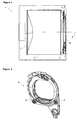
Figure 1 - is the schematic view of a dryer. -
Figure 2 - is the rear perspective view of the bearing member and the rollers. -
Figure 3 - is the detailed front view of the bearing member, the roller and the lid. -
Figure 4 - is the detailed rear view of the bearing member, the roller and the lid. -
Figure 5 - is another detailed rear view of the bearing member, the roller and the lid. -
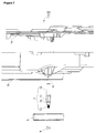
Figure 6 - is the cross-sectional view of the bearing member, the roller and the lid. -
Figure 7 - is the exploded view of the bearing member, the roller and the lid. -
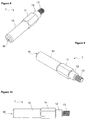
Figure 8 - is the front perspective view of the shaft. -
Figure 9 - is the rear perspective view of the shaft. -
Figure 10 - is the sideways view of the shaft. - The elements illustrated in the figures are numbered as follows:
- 1. Dryer
- 2. Drum
- 3. Body
- 4. Front wall
- 5. Roller
- 6. Bearing member
- 7. Shaft
- 8. Housing
- 9. Fixing means
- 10. Entry section
- 11. Fitting section
- 12. Axle section
- 13. Threaded section
- 14. Lid
- 15. Locking means
- 16. Bore
- 17. Screw
- 18. Stopper
- The dryer (1) of the present invention comprises a drum (2) that is rotated around its own horizontal axis (
Figure 1 ). The dryer (1) of the present invention is a horizontal axis dryer (1). - The drum (2) comprises a cylindrical body (3), and a ring-shaped front wall (4) forming the front surface of the body (3) (
Figure 1 ). - The dryer (1), furthermore, comprises
- more than one roller (5) whereon the front wall (4) is seated and which have a rotational axis parallel with the rotational axis (X) of the drum (2), and support the drum (2) by rotating around themselves during the drying process by the rotational movement of the drum (2),
- a bearing member (6) whereon the rollers (5) are borne by being mounted thereon,
- one shaft (7) each, which provides each roller (5) to be rotatably mounted to the bearing member (6),
- more than one cylindrical-shaped housing (8) which are located at the bearing member (6) face that faces the drum (2), and wherein the shafts (7) are at least partially snap-fittingly inserted, and
- at least one fixing means (9) which provides the roller (5) to be fixed to the shaft (7) (
Figures 2 to 7 ). - The shaft (7) comprises
- an entry section (10) which has a cylindrical cross-section, which is located at the end side of the shaft (7) and which is the portion of the shaft (7) that enters the housing (8) first
- a fitting section (11) which has a polygonal cross-section and a diameter wider than the diameter of the entry section (10), which is located behind the entry section (10) and which provides the shaft (7) to be fixed to the housing (8),
- an axle section (12) which remains outside the housing (8), which has a cylindrical cross-section and whereon the roller (5) is mounted, and
- a threaded section (13) whereon the fixing means (9) is mounted and thus, which provides the roller (5) to be rotatably mounted to the shaft (7) such that the roller (5) will remain between the fixing means (9) and the fitting section (11) (
Figures 8 to 10 ). - The shafts (7) are produced by a rod, which entirely has a polygonal cross-section, being processed such that an entry section (10), an axle section (12) and a threaded section (13) will be formed. The fitting section (11) has preferably a hexagonal cross-section (
Figures 8 to 10 ). - In an embodiment of the present invention, the shaft (7) is nailed to the housing (8) in a short time after the production of the bearing member (6), while the bearing member (6) is still warm. Thus, the nailing process is provided to be easily performed. By the cooling of the bearing member (6), the housing (8) becomes narrow and thus, bears against the fitting section (11) and even against the entry section (10) of the shaft (7) inserted therein. Thus, the snap-fit fixing of the shaft (7) onto the bearing member (6) is performed.
- In another embodiment of the present invention, the bearing member (6) is produced by being shaped by means of a mould, and the shaft (7) is inserted into the mould during the production of the bearing member (6) and thus, comes out of the mould together with the bearing member (6). Thus, the shaft (7) is provided to be strongly fixed onto the bearing member (6).
- Then, the roller (5) is mounted to the axle section (12) of the shaft (7) and by the fixing means (9) being mounted onto the threaded section (13) that remains in front of the roller (5), the assembly of the roller (5) onto the shaft (7) is performed. The fixing means (9) is preferably a nut (
Figure 7 ). - By means of the polygonal shape of the fitting section (11), the shaft (7) is provided to be centered inside the housing (8) and rotation of the shaft (7) inside the housing (8) caused by the loosening of the connection by the effect of the loads that act on the shaft (7) during the rotation of the drum (2) is prevented.
- The dryer (1), furthermore, comprises a lid (14) covering the bearing member (6) face that does not face the drum (2). The bearing member (6) and the lid (14) comprise opposite locking means (15) that enable them to be fixed to each other by shape-locking (
Figure 6 ). By means of this shape-locking structure, the forces acting on the shaft (7) are not only carried by the bearing member (6) whereon the shaft (7) is mounted, but also by the locking means (15) and therefore, by the lid (14), and the strength is improved. - The shaft (7) comprises a bore (16) wherein a thread is cut and which is located at the shaft (7) end wherein the entry section (10) is situated. Accordingly, the bearing member (6) and the lid (14) comprise screw holes which are aligned with the bore (16) when the bearing member (6), the shaft (7) and the lid (14) are brought together. The dryer (1), furthermore, comprises a screw (17) which is mounted in the bore (16) by passing through the screw holes on the bearing member (6) and on the lid (14) (
Figure 6 andFigure 7 ). Besides being a secondary means for the fixing of the bearing member (6) and the lid (14) to each other, the screw (17) also causes the shaft (7) to be drawn towards itself by locking to the threaded form inside the bore (16). Thus, the shaft (7) is provided to be tightly fixed and to be held in the desired position, and is prevented from loosening in the course of time. - The bearing member (6) comprises stoppers (18) that are located at the edges of the screw hole, at the base of the housing (8) and that prevent the shaft (7) from proceeding more than desired during its nailing into the housing (8) (
Figure 7 ). - In an embodiment of the present invention, the roller (5), the bearing member (6) and the lid (14) are assembled by the assembly method that is explained below.
- While the bearing member (6) is warm, the shaft (7) is nailed to the housing (8) (101),
- by the cooling of the bearing member (6), the housing (8) becomes narrow and thus, bears against the fitting section (11) and the entry section (10) of the shaft (7) inserted therein (102),
- to the axle section (12), the roller (5) is mounted (103),
- onto the threaded section (13) remaining in front of the roller (5), the fixing means (9) is mounted (104),
- the bearing member (6) and the lid (14) are fixed to each other by shape-locking by means of the locking means (15) (105),
- the screw (17) passes through the screw holes on the bearing member (6) and on the lid (14) and locks to the threaded form inside the bore (16), and causes the shaft (7) to be drawn towards itself (106).
- Thus, the forces occurring during the operation of the dryer (1) are provided to be efficiently distributed between the roller (5), the bearing member (6), the shaft (7) and the lid (14), furthermore, a bearing with high strength, the assembly of which is performed in a short time and easily, is provided.
- It is to be understood that the present invention is not limited to the embodiments disclosed above and a skilled person in the art can easily introduce different embodiments. These should be considered within the scope of the protection postulated by the claims of the present invention.
Claims (9)
- A dryer (1) comprising- a drum (2) which can rotate around itself, and which has a horizontal-axial, cylindrical body (3) and a ring-shaped front wall (4) that forms the front surface of the body (3),- more than one roller (5) whereon the front wall (4) is seated and which have a rotational axis parallel with the rotational axis (X) of the drum (2), and support the drum (2) by rotating around themselves during the drying process by the rotational movement of the drum (2),- a bearing member (6) whereon the rollers (5) are borne by being mounted thereon,- one shaft (7) each, which provides each roller (5) to be rotatably mounted to the bearing member (6),- cylindrical-shaped housings (8) which are located at the bearing member (6) face that faces the drum (2), and wherein the shafts (7) are at least partially inserted, and- at least one fixing means (9) which provides the roller (5) to be fixed to the shaft (7),characterized by the shaft (7) that has- an entry section (10) which has a cylindrical cross-section, and which is the portion of the shaft (7) that enters the housing (8) first, and- a fitting section (11) which has a polygonal cross-section and a diameter wider than the diameter of the entry section (10), and which provides the shaft (7) to be fixed to the housing (8),wherein- a) the shaft (7) is nailed to the housing (8) while the bearing member (6) is warm,
or- b) the bearing member (6) is produced by being shaped by means of a mould, and the shaft (7) is inserted into the mould during the production of the bearing member (6) and thus, comes out of the mould together with the bearing member (6). - A dryer (1) as in Claim 1, characterized by the shaft (7) that has- an axle section (12) which remains outside the housing (8), which has a cylindrical cross-section and whereon the roller (5) is mounted, and- a threaded section (13) whereon the fixing means (9) is mounted and thus, which provides the roller (5) to be rotatably mounted to the shaft (7) such that the roller (5) will remain between the fixing means (9) and the fitting section (11).
- A dryer (1) as in Claim 1 or 2, characterized by the fitting section (11) that has a hexagonal cross-section.
- A dryer (1) as in any one of the above Claims, characterized by a lid (14) which covers one face of the bearing member (6) whereby said face covered by the lid (14) is the face of the bearing member (6) that does not face the drum (2).
- A dryer (1) as in Claim 4, characterized by the bearing member (6) and the lid (14) comprising opposite locking means (15) which enable the bearing member (6) and the lid (14) to be fixed to each other by shape-locking.
- A dryer (1) as in Claim 4 or 5, characterized by the shaft (7) that has a bore (16), the inside of which is formed as threaded, and which is located at the shaft (7) end wherein the entry section (10) is situated, and by the bearing member (6) and the lid (14) that have screw holes which are aligned with the bore (16) when the bearing member (6), the shaft (7) and the lid (14) are brought together.
- A dryer (1) as in Claim 6, characterized by the screw (17) which is mounted in the bore (16) by passing through the screw holes on the bearing member (6) and on the lid (14).
- A dryer (1) as in any one of the above Claims, characterized by the bearing member (6) which comprises stoppers (18) that are located at the edges of the screw hole, at the base of the housing (8) and that prevent the shaft (7) from proceeding more than desired during its nailing into the housing (8).
- An assembly method for a dryer (1) as in Claims 7 or 8, comprising the following steps:as a first step,- a) nailing the shaft (7) to the housing (8) while the bearing member (6) is warm (101), or- b) inserting the shaft (7) into the mould during the production of the bearing member (6) such that the shaft (7) comes out of the mould together with the bearing member (6) that is produced by being shaped by means of a mould,and as following steps,- bearing the bearing member (6) against the fitting section (11) and the entry section (10) of the shaft (7) inserted therein by the housing (8) becoming narrow by the cooling of the bearing member (6) (102),- mounting the roller (5) to the axle section (12) (103),- mounting the fixing means (9) onto the threaded section (13) that remains in front of the roller (5) (104),- fixing the bearing member (6) and the lid (14) to each other by shape-locking by means of the locking means (15) (105),- locking the screw (17) to the threaded form inside the bore (16) by passing through the screw holes on the bearing member (6) and on the lid (14) and causing the shaft (7) to be drawn towards the screw (17) (106).
Applications Claiming Priority (2)
| Application Number | Priority Date | Filing Date | Title |
|---|---|---|---|
| TR200809932 | 2008-12-29 | ||
| PCT/EP2009/066631 WO2010076128A1 (en) | 2008-12-29 | 2009-12-08 | A dryer comprising a drum the front bearing of which is performed by rollers |
Publications (2)
| Publication Number | Publication Date |
|---|---|
| EP2376701A1 EP2376701A1 (en) | 2011-10-19 |
| EP2376701B1 true EP2376701B1 (en) | 2016-08-10 |
Family
ID=42079102
Family Applications (1)
| Application Number | Title | Priority Date | Filing Date |
|---|---|---|---|
| EP09775154.9A Active EP2376701B1 (en) | 2008-12-29 | 2009-12-08 | A dryer comprising a drum the front bearing of which is performed by rollers |
Country Status (3)
| Country | Link |
|---|---|
| EP (1) | EP2376701B1 (en) |
| ES (1) | ES2601904T3 (en) |
| WO (1) | WO2010076128A1 (en) |
Families Citing this family (2)
| Publication number | Priority date | Publication date | Assignee | Title |
|---|---|---|---|---|
| WO2012062887A2 (en) * | 2010-11-12 | 2012-05-18 | Arcelik Anonim Sirketi | A dryer comprising a drum the front bearing of which is performed by wheels |
| EP2843117A1 (en) * | 2013-08-27 | 2015-03-04 | Electrolux Appliances Aktiebolag | Rotary-drum laundry dryer |
Family Cites Families (4)
| Publication number | Priority date | Publication date | Assignee | Title |
|---|---|---|---|---|
| US2769246A (en) * | 1953-05-06 | 1956-11-06 | Murray Corp | Clothes drier |
| US3409997A (en) * | 1965-01-13 | 1968-11-12 | Whirlpool Co | Dryer with open end drum |
| DE19615822C1 (en) * | 1996-04-20 | 1997-05-07 | Bauknecht Hausgeraete | Laundry dryer has drum guided by rollers |
| DE10358131B3 (en) * | 2003-12-12 | 2005-01-05 | Miele & Cie. Kg | Laundry dryer with rotating laundry drum supported by bearing rollers adjacent loading opening with safety disc filling gap between carrier for roller axis and side face of rotating bearing roller |
-
2009
- 2009-12-08 WO PCT/EP2009/066631 patent/WO2010076128A1/en not_active Ceased
- 2009-12-08 ES ES09775154.9T patent/ES2601904T3/en active Active
- 2009-12-08 EP EP09775154.9A patent/EP2376701B1/en active Active
Also Published As
| Publication number | Publication date |
|---|---|
| EP2376701A1 (en) | 2011-10-19 |
| ES2601904T3 (en) | 2017-02-16 |
| WO2010076128A1 (en) | 2010-07-08 |
Similar Documents
| Publication | Publication Date | Title |
|---|---|---|
| US5746070A (en) | Plastic and stainless steel horizontal axis spin tub | |
| US9637853B2 (en) | Washing machine and balancer thereof | |
| KR101222861B1 (en) | Shaft-flange and washing machine having the same | |
| US20090199365A1 (en) | Stepped pin assembly for an axle and method therefor | |
| WO2010076128A1 (en) | A dryer comprising a drum the front bearing of which is performed by rollers | |
| US20160258102A1 (en) | Balancer of washing machine | |
| KR101638903B1 (en) | Washing machine | |
| KR101141638B1 (en) | direct drive motor in washing machine | |
| US9139945B2 (en) | Bearing housing, water tub for washing machine and manufacturing mold unit thereof | |
| KR100505233B1 (en) | drum washer | |
| US8174162B2 (en) | Motor and washing machine using the same | |
| EP1798016B1 (en) | Bearing-holder support for rotating elements | |
| US11846057B2 (en) | Stabilizer for a rotatable drum | |
| US7520147B2 (en) | Anchorage device for fastening a counterweight to a washing machine tub | |
| CN209873396U (en) | Roller assembly assembly and clothes dryer | |
| EP0736117B1 (en) | Improvement in the washing tub of a clothes washing machine | |
| WO2005033400A3 (en) | Plastic container for washing machines or tumble dryers | |
| DE10052586C1 (en) | Front-loading washing machine or washer/dryer has washing drum supported by 2 axially spaced radial ball bearings providing depth adjustment | |
| EP2129822A1 (en) | A washer/dryer | |
| JP2008228424A (en) | motor | |
| CN107354669B (en) | Clothes treating device | |
| IT202000008122A1 (en) | DEVICE FOR SUPPORTING AND TIGHTENING THE SHAFT OF A COIL | |
| WO2019132811A1 (en) | A washer-dryer comprising a flange | |
| JP2004216166A (en) | Drum type washing machine | |
| EP3894623B1 (en) | A washer/dryer comprising a balance weight |
Legal Events
| Date | Code | Title | Description |
|---|---|---|---|
| PUAI | Public reference made under article 153(3) epc to a published international application that has entered the european phase |
Free format text: ORIGINAL CODE: 0009012 |
|
| 17P | Request for examination filed |
Effective date: 20110610 |
|
| AK | Designated contracting states |
Kind code of ref document: A1 Designated state(s): AT BE BG CH CY CZ DE DK EE ES FI FR GB GR HR HU IE IS IT LI LT LU LV MC MK MT NL NO PL PT RO SE SI SK SM TR |
|
| DAX | Request for extension of the european patent (deleted) | ||
| 17Q | First examination report despatched |
Effective date: 20150626 |
|
| GRAP | Despatch of communication of intention to grant a patent |
Free format text: ORIGINAL CODE: EPIDOSNIGR1 |
|
| INTG | Intention to grant announced |
Effective date: 20160425 |
|
| GRAS | Grant fee paid |
Free format text: ORIGINAL CODE: EPIDOSNIGR3 |
|
| GRAA | (expected) grant |
Free format text: ORIGINAL CODE: 0009210 |
|
| AK | Designated contracting states |
Kind code of ref document: B1 Designated state(s): AT BE BG CH CY CZ DE DK EE ES FI FR GB GR HR HU IE IS IT LI LT LU LV MC MK MT NL NO PL PT RO SE SI SK SM TR |
|
| REG | Reference to a national code |
Ref country code: GB Ref legal event code: FG4D |
|
| REG | Reference to a national code |
Ref country code: CH Ref legal event code: EP Ref country code: AT Ref legal event code: REF Ref document number: 819174 Country of ref document: AT Kind code of ref document: T Effective date: 20160815 |
|
| REG | Reference to a national code |
Ref country code: IE Ref legal event code: FG4D |
|
| REG | Reference to a national code |
Ref country code: DE Ref legal event code: R096 Ref document number: 602009040289 Country of ref document: DE |
|
| REG | Reference to a national code |
Ref country code: LT Ref legal event code: MG4D |
|
| REG | Reference to a national code |
Ref country code: NL Ref legal event code: MP Effective date: 20160810 |
|
| REG | Reference to a national code |
Ref country code: FR Ref legal event code: PLFP Year of fee payment: 8 |
|
| REG | Reference to a national code |
Ref country code: AT Ref legal event code: MK05 Ref document number: 819174 Country of ref document: AT Kind code of ref document: T Effective date: 20160810 |
|
| PG25 | Lapsed in a contracting state [announced via postgrant information from national office to epo] |
Ref country code: NO Free format text: LAPSE BECAUSE OF FAILURE TO SUBMIT A TRANSLATION OF THE DESCRIPTION OR TO PAY THE FEE WITHIN THE PRESCRIBED TIME-LIMIT Effective date: 20161110 Ref country code: NL Free format text: LAPSE BECAUSE OF FAILURE TO SUBMIT A TRANSLATION OF THE DESCRIPTION OR TO PAY THE FEE WITHIN THE PRESCRIBED TIME-LIMIT Effective date: 20160810 Ref country code: IS Free format text: LAPSE BECAUSE OF FAILURE TO SUBMIT A TRANSLATION OF THE DESCRIPTION OR TO PAY THE FEE WITHIN THE PRESCRIBED TIME-LIMIT Effective date: 20161210 Ref country code: LT Free format text: LAPSE BECAUSE OF FAILURE TO SUBMIT A TRANSLATION OF THE DESCRIPTION OR TO PAY THE FEE WITHIN THE PRESCRIBED TIME-LIMIT Effective date: 20160810 Ref country code: FI Free format text: LAPSE BECAUSE OF FAILURE TO SUBMIT A TRANSLATION OF THE DESCRIPTION OR TO PAY THE FEE WITHIN THE PRESCRIBED TIME-LIMIT Effective date: 20160810 Ref country code: HR Free format text: LAPSE BECAUSE OF FAILURE TO SUBMIT A TRANSLATION OF THE DESCRIPTION OR TO PAY THE FEE WITHIN THE PRESCRIBED TIME-LIMIT Effective date: 20160810 |
|
| REG | Reference to a national code |
Ref country code: ES Ref legal event code: FG2A Ref document number: 2601904 Country of ref document: ES Kind code of ref document: T3 Effective date: 20170216 |
|
| PG25 | Lapsed in a contracting state [announced via postgrant information from national office to epo] |
Ref country code: SE Free format text: LAPSE BECAUSE OF FAILURE TO SUBMIT A TRANSLATION OF THE DESCRIPTION OR TO PAY THE FEE WITHIN THE PRESCRIBED TIME-LIMIT Effective date: 20160810 Ref country code: PL Free format text: LAPSE BECAUSE OF FAILURE TO SUBMIT A TRANSLATION OF THE DESCRIPTION OR TO PAY THE FEE WITHIN THE PRESCRIBED TIME-LIMIT Effective date: 20160810 Ref country code: PT Free format text: LAPSE BECAUSE OF FAILURE TO SUBMIT A TRANSLATION OF THE DESCRIPTION OR TO PAY THE FEE WITHIN THE PRESCRIBED TIME-LIMIT Effective date: 20161212 Ref country code: LV Free format text: LAPSE BECAUSE OF FAILURE TO SUBMIT A TRANSLATION OF THE DESCRIPTION OR TO PAY THE FEE WITHIN THE PRESCRIBED TIME-LIMIT Effective date: 20160810 Ref country code: AT Free format text: LAPSE BECAUSE OF FAILURE TO SUBMIT A TRANSLATION OF THE DESCRIPTION OR TO PAY THE FEE WITHIN THE PRESCRIBED TIME-LIMIT Effective date: 20160810 Ref country code: GR Free format text: LAPSE BECAUSE OF FAILURE TO SUBMIT A TRANSLATION OF THE DESCRIPTION OR TO PAY THE FEE WITHIN THE PRESCRIBED TIME-LIMIT Effective date: 20161111 |
|
| PGFP | Annual fee paid to national office [announced via postgrant information from national office to epo] |
Ref country code: ES Payment date: 20161213 Year of fee payment: 8 |
|
| PG25 | Lapsed in a contracting state [announced via postgrant information from national office to epo] |
Ref country code: EE Free format text: LAPSE BECAUSE OF FAILURE TO SUBMIT A TRANSLATION OF THE DESCRIPTION OR TO PAY THE FEE WITHIN THE PRESCRIBED TIME-LIMIT Effective date: 20160810 Ref country code: RO Free format text: LAPSE BECAUSE OF FAILURE TO SUBMIT A TRANSLATION OF THE DESCRIPTION OR TO PAY THE FEE WITHIN THE PRESCRIBED TIME-LIMIT Effective date: 20160810 |
|
| REG | Reference to a national code |
Ref country code: DE Ref legal event code: R097 Ref document number: 602009040289 Country of ref document: DE |
|
| PG25 | Lapsed in a contracting state [announced via postgrant information from national office to epo] |
Ref country code: BG Free format text: LAPSE BECAUSE OF FAILURE TO SUBMIT A TRANSLATION OF THE DESCRIPTION OR TO PAY THE FEE WITHIN THE PRESCRIBED TIME-LIMIT Effective date: 20161110 Ref country code: SK Free format text: LAPSE BECAUSE OF FAILURE TO SUBMIT A TRANSLATION OF THE DESCRIPTION OR TO PAY THE FEE WITHIN THE PRESCRIBED TIME-LIMIT Effective date: 20160810 Ref country code: BE Free format text: LAPSE BECAUSE OF FAILURE TO SUBMIT A TRANSLATION OF THE DESCRIPTION OR TO PAY THE FEE WITHIN THE PRESCRIBED TIME-LIMIT Effective date: 20160810 Ref country code: CZ Free format text: LAPSE BECAUSE OF FAILURE TO SUBMIT A TRANSLATION OF THE DESCRIPTION OR TO PAY THE FEE WITHIN THE PRESCRIBED TIME-LIMIT Effective date: 20160810 Ref country code: SM Free format text: LAPSE BECAUSE OF FAILURE TO SUBMIT A TRANSLATION OF THE DESCRIPTION OR TO PAY THE FEE WITHIN THE PRESCRIBED TIME-LIMIT Effective date: 20160810 Ref country code: DK Free format text: LAPSE BECAUSE OF FAILURE TO SUBMIT A TRANSLATION OF THE DESCRIPTION OR TO PAY THE FEE WITHIN THE PRESCRIBED TIME-LIMIT Effective date: 20160810 |
|
| PLBE | No opposition filed within time limit |
Free format text: ORIGINAL CODE: 0009261 |
|
| STAA | Information on the status of an ep patent application or granted ep patent |
Free format text: STATUS: NO OPPOSITION FILED WITHIN TIME LIMIT |
|
| PGFP | Annual fee paid to national office [announced via postgrant information from national office to epo] |
Ref country code: IT Payment date: 20161223 Year of fee payment: 8 |
|
| 26N | No opposition filed |
Effective date: 20170511 |
|
| REG | Reference to a national code |
Ref country code: CH Ref legal event code: PL |
|
| PG25 | Lapsed in a contracting state [announced via postgrant information from national office to epo] |
Ref country code: SI Free format text: LAPSE BECAUSE OF FAILURE TO SUBMIT A TRANSLATION OF THE DESCRIPTION OR TO PAY THE FEE WITHIN THE PRESCRIBED TIME-LIMIT Effective date: 20160810 |
|
| PG25 | Lapsed in a contracting state [announced via postgrant information from national office to epo] |
Ref country code: MC Free format text: LAPSE BECAUSE OF FAILURE TO SUBMIT A TRANSLATION OF THE DESCRIPTION OR TO PAY THE FEE WITHIN THE PRESCRIBED TIME-LIMIT Effective date: 20160810 |
|
| REG | Reference to a national code |
Ref country code: IE Ref legal event code: MM4A |
|
| PG25 | Lapsed in a contracting state [announced via postgrant information from national office to epo] |
Ref country code: LI Free format text: LAPSE BECAUSE OF NON-PAYMENT OF DUE FEES Effective date: 20161231 Ref country code: LU Free format text: LAPSE BECAUSE OF NON-PAYMENT OF DUE FEES Effective date: 20161208 Ref country code: CH Free format text: LAPSE BECAUSE OF NON-PAYMENT OF DUE FEES Effective date: 20161231 |
|
| PG25 | Lapsed in a contracting state [announced via postgrant information from national office to epo] |
Ref country code: IE Free format text: LAPSE BECAUSE OF NON-PAYMENT OF DUE FEES Effective date: 20161208 |
|
| REG | Reference to a national code |
Ref country code: FR Ref legal event code: PLFP Year of fee payment: 9 |
|
| PG25 | Lapsed in a contracting state [announced via postgrant information from national office to epo] |
Ref country code: HU Free format text: LAPSE BECAUSE OF FAILURE TO SUBMIT A TRANSLATION OF THE DESCRIPTION OR TO PAY THE FEE WITHIN THE PRESCRIBED TIME-LIMIT; INVALID AB INITIO Effective date: 20091208 Ref country code: CY Free format text: LAPSE BECAUSE OF FAILURE TO SUBMIT A TRANSLATION OF THE DESCRIPTION OR TO PAY THE FEE WITHIN THE PRESCRIBED TIME-LIMIT Effective date: 20160810 |
|
| PG25 | Lapsed in a contracting state [announced via postgrant information from national office to epo] |
Ref country code: MK Free format text: LAPSE BECAUSE OF FAILURE TO SUBMIT A TRANSLATION OF THE DESCRIPTION OR TO PAY THE FEE WITHIN THE PRESCRIBED TIME-LIMIT Effective date: 20160810 |
|
| PG25 | Lapsed in a contracting state [announced via postgrant information from national office to epo] |
Ref country code: MT Free format text: LAPSE BECAUSE OF NON-PAYMENT OF DUE FEES Effective date: 20161208 |
|
| PG25 | Lapsed in a contracting state [announced via postgrant information from national office to epo] |
Ref country code: IT Free format text: LAPSE BECAUSE OF NON-PAYMENT OF DUE FEES Effective date: 20171208 |
|
| REG | Reference to a national code |
Ref country code: ES Ref legal event code: FD2A Effective date: 20190703 |
|
| PG25 | Lapsed in a contracting state [announced via postgrant information from national office to epo] |
Ref country code: ES Free format text: LAPSE BECAUSE OF NON-PAYMENT OF DUE FEES Effective date: 20171209 |
|
| PGFP | Annual fee paid to national office [announced via postgrant information from national office to epo] |
Ref country code: DE Payment date: 20251211 Year of fee payment: 17 |
|
| PGFP | Annual fee paid to national office [announced via postgrant information from national office to epo] |
Ref country code: GB Payment date: 20251219 Year of fee payment: 17 |
|
| PGFP | Annual fee paid to national office [announced via postgrant information from national office to epo] |
Ref country code: FR Payment date: 20251222 Year of fee payment: 17 |
|
| PGFP | Annual fee paid to national office [announced via postgrant information from national office to epo] |
Ref country code: TR Payment date: 20251124 Year of fee payment: 17 |