EP2375977B1 - Detection of dynamic hyperinflation in spontaneously breathing mechanically ventilated patients - Google Patents
Detection of dynamic hyperinflation in spontaneously breathing mechanically ventilated patients Download PDFInfo
- Publication number
- EP2375977B1 EP2375977B1 EP10730988.2A EP10730988A EP2375977B1 EP 2375977 B1 EP2375977 B1 EP 2375977B1 EP 10730988 A EP10730988 A EP 10730988A EP 2375977 B1 EP2375977 B1 EP 2375977B1
- Authority
- EP
- European Patent Office
- Prior art keywords
- during
- patient
- breath
- inspiratory
- dynamic hyperinflation
- Prior art date
- Legal status (The legal status is an assumption and is not a legal conclusion. Google has not performed a legal analysis and makes no representation as to the accuracy of the status listed.)
- Active
Links
Images


Classifications
-
- A—HUMAN NECESSITIES
- A61—MEDICAL OR VETERINARY SCIENCE; HYGIENE
- A61M—DEVICES FOR INTRODUCING MEDIA INTO, OR ONTO, THE BODY; DEVICES FOR TRANSDUCING BODY MEDIA OR FOR TAKING MEDIA FROM THE BODY; DEVICES FOR PRODUCING OR ENDING SLEEP OR STUPOR
- A61M16/00—Devices for influencing the respiratory system of patients by gas treatment, e.g. ventilators; Tracheal tubes
- A61M16/0051—Devices for influencing the respiratory system of patients by gas treatment, e.g. ventilators; Tracheal tubes with alarm devices
-
- A—HUMAN NECESSITIES
- A61—MEDICAL OR VETERINARY SCIENCE; HYGIENE
- A61B—DIAGNOSIS; SURGERY; IDENTIFICATION
- A61B5/00—Measuring for diagnostic purposes; Identification of persons
- A61B5/08—Measuring devices for evaluating the respiratory organs
- A61B5/091—Measuring volume of inspired or expired gases, e.g. to determine lung capacity
-
- A—HUMAN NECESSITIES
- A61—MEDICAL OR VETERINARY SCIENCE; HYGIENE
- A61M—DEVICES FOR INTRODUCING MEDIA INTO, OR ONTO, THE BODY; DEVICES FOR TRANSDUCING BODY MEDIA OR FOR TAKING MEDIA FROM THE BODY; DEVICES FOR PRODUCING OR ENDING SLEEP OR STUPOR
- A61M16/00—Devices for influencing the respiratory system of patients by gas treatment, e.g. ventilators; Tracheal tubes
- A61M16/0003—Accessories therefor, e.g. sensors, vibrators, negative pressure
-
- A—HUMAN NECESSITIES
- A61—MEDICAL OR VETERINARY SCIENCE; HYGIENE
- A61M—DEVICES FOR INTRODUCING MEDIA INTO, OR ONTO, THE BODY; DEVICES FOR TRANSDUCING BODY MEDIA OR FOR TAKING MEDIA FROM THE BODY; DEVICES FOR PRODUCING OR ENDING SLEEP OR STUPOR
- A61M16/00—Devices for influencing the respiratory system of patients by gas treatment, e.g. ventilators; Tracheal tubes
- A61M16/021—Devices for influencing the respiratory system of patients by gas treatment, e.g. ventilators; Tracheal tubes operated by electrical means
- A61M16/022—Control means therefor
- A61M16/024—Control means therefor including calculation means, e.g. using a processor
-
- A—HUMAN NECESSITIES
- A61—MEDICAL OR VETERINARY SCIENCE; HYGIENE
- A61M—DEVICES FOR INTRODUCING MEDIA INTO, OR ONTO, THE BODY; DEVICES FOR TRANSDUCING BODY MEDIA OR FOR TAKING MEDIA FROM THE BODY; DEVICES FOR PRODUCING OR ENDING SLEEP OR STUPOR
- A61M16/00—Devices for influencing the respiratory system of patients by gas treatment, e.g. ventilators; Tracheal tubes
- A61M16/0003—Accessories therefor, e.g. sensors, vibrators, negative pressure
- A61M2016/003—Accessories therefor, e.g. sensors, vibrators, negative pressure with a flowmeter
-
- A—HUMAN NECESSITIES
- A61—MEDICAL OR VETERINARY SCIENCE; HYGIENE
- A61M—DEVICES FOR INTRODUCING MEDIA INTO, OR ONTO, THE BODY; DEVICES FOR TRANSDUCING BODY MEDIA OR FOR TAKING MEDIA FROM THE BODY; DEVICES FOR PRODUCING OR ENDING SLEEP OR STUPOR
- A61M16/00—Devices for influencing the respiratory system of patients by gas treatment, e.g. ventilators; Tracheal tubes
- A61M16/0003—Accessories therefor, e.g. sensors, vibrators, negative pressure
- A61M2016/003—Accessories therefor, e.g. sensors, vibrators, negative pressure with a flowmeter
- A61M2016/0033—Accessories therefor, e.g. sensors, vibrators, negative pressure with a flowmeter electrical
- A61M2016/0036—Accessories therefor, e.g. sensors, vibrators, negative pressure with a flowmeter electrical in the breathing tube and used in both inspiratory and expiratory phase
Definitions
- the present invention relates to a method and device for determining dynamic hyperinflation during mechanical ventilation of a spontaneously breathing patient.
- Intrinsic positive end-expiratory pressure is a phenomena occurring due to insufficient expiratory time, preventing the lungs of a patient from becoming sufficiently emptied at the end of expiration, trapping air in the lungs, and increasing the end-expiratory lung volume (dynamic hyperinflation).
- PEEPi intrinsic PEEP
- a method for determining dynamic hyperinflation during mechanical ventilation of a spontaneously breathing patient comprising: removing mechanical ventilation during one breath of the patient; measuring inspiratory and expiratory volumes of the patient during said one breath; calculating a difference between the inspiratory and expiratory volumes measured during said one breath; and indicating dynamic hyperinflation of the patient's lungs in relation to the calculated difference.
- a device adapted to determine dynamic hyperinflation during mechanical ventilation of a spontaneously breathing patient, comprising: a controller for removing mechanical ventilation during one breath of the patient; a sensor of inspiratory and expiratory volumes of the patient during said one breath; a calculator of a difference between the inspiratory and expiratory volumes sensed during said one breath; and an indicator responsive to the calculated difference to indicate dynamic hyperinflation of the patient's lungs .
- the concept of air-trapping relates to a quantity of air penetrating the lungs of a patient larger than the quantity of air leaving the patient's lungs. Air-trapping induced by mechanical ventilation actually worsens contractility of the inspiratory muscles due to dynamic hyperinflation until a level where weakness of the inspiratory muscles and added mechanical ventilation reach an equilibrium causing inspiratory (Vins) and expiratory (Vexp) volumes to match.
- FIG. 1 of the appended drawings illustrates a device 100 for determining dynamic hyperinflation during mechanical ventilation of a spontaneously breathing patient.
- the device 100 of Figure 1 comprises a sensor 101 of inspiratory (Vins) and expiratory (Vexp) volumes of a patient 102.
- the sensor 101 may comprise a pneumotachograph or any other suitable sensor.
- the sensor 101 is connected to the patient's airways to detect the inspiratory (Vins) and expiratory (Vexp) volumes.
- a calculator 103 is responsive to the inspiratory (Vins) and expiratory (Vexp) volumes detected by the sensor 101 to calculate a difference between the detected inspiratory (Vins) and expiratory (Vexp) volumes of the patient.
- An indicator 104 is responsive to the difference between the detected inspiratory (Vins) and expiratory (Vexp) volumes of the patient, for example the ratio Vins/Vexp, to indicate dynamic hyperinflation.
- a controller 105 is connected to the sensor 101, the calculator 103 and a mechanical ventilator 106 providing mechanical ventilation to the patient 102.
- a method 200 ( Figure 2 ) for determining dynamic hyperinflation during mechanical ventilation of a spontaneously breathing patient using the device of Figure 1 will now be described with reference both to Figures 1 and 2 .
- the controller 105 controls the mechanical ventilator 106 ( Figure 1 ) to remove mechanical ventilation of the patient 102 ( Figure 1 ) during one (1) breath of the patient 102 ( Figure 1 ).
- the controller 105 controls the sensor 101 ( Figure 1 ), for example a pneumotachograph, to measure:
- the senor 101 ( Figure 1 ) is connected to the airways of the patient 102 ( Figure 1 ).
- the controller 105 ( Figure 1 ) also commands the calculator 103 ( Figure 1 ) to calculate a difference between the inspiratory volume (Vins) and the expiratory volume (Vexp) as measured by the sensor 101 ( Figure 1 ) during the one (1) breath during which mechanical ventilation of the patient 102 ( Figure 1 ) by the mechanical ventilator 106 ( Figure 1 ) is removed.
- the calculated difference can be expressed either in absolute (for example a mathematical difference between Vins and Vexp) or relative (for example a ratio between Vins and Vexp) terms.
- the calculator 103 calculates the difference between the inspiratory volume (Vins) and the expiratory volume (Vexp) as measured by the sensor 101 ( Figure 1 ), for example a ratio (Vins/Vexp) between these inspiratory (Vins) and expiratory (Vexp) volumes as measured by the sensor 101 during the one (1) breath during which mechanical ventilation of the patient 102 ( Figure 1 ) by the mechanical ventilator 106 ( Figure 1 ) is removed.
- An indicator 104 ( Figure 1 ) is responsive to the ratio (Vins/Vexp) from the calculator 103 ( Figure 1 ) to indicate dynamic hyperinflation of the patient.
- the indicator 104 may produce a light signal going from e.g. green if the ratio (Vins/Vexp) is close to 1 to indicate that dynamic hyperinflation is not present and change towards e.g. red if the ratio (Vins/Vexp) is close to 0 to indicate that dynamic hyperinflation is present.
- the ratio (Vins/Vexp) could be used to guide conventional titration of external PEEP, or in combination with previous neural PEEP titration methods ( US Published Patent Applications 2005/0211246 and 2003/0226565 ).
- Figure 3 represents graphs showing volume and airway pressure (Paw) over time during breaths with mechanical ventilation and breaths without mechanical ventilation.
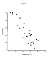
- the points show how the ratio (Vins/Vexp) decreases with increasing levels of mechanical ventilation of the patient 102 ( Figure 1 ) by the mechanical ventilator 106 ( Figure 1 ) when the patient 102 breathes against a high inspiratory and expiratory resistive load.
- the sensor 101 may measure during operation 202 the inspiratory volume (Vins) and the expiratory volume (Vexp) during a plurality of successive or non successive singles breaths during which mechanical ventilation of the patient 102 ( Figure 1 ) by the mechanical ventilator 106 ( Figure 1 ) is removed.
- the calculator 103 ( Figure 1 ) then compute the ratio (Vins/Vexp) for example as an average of the ratios (Vins/Vexp) calculated from the inspiratory (Vins) and expiratory (Vexp) volumes measured by the sensor 101 during the respective single breaths without mechanical ventilation.
- the above described method 200 ( Figure 2 ) for determining dynamic hyperinflation during mechanical ventilation of a spontaneously breathing patient can be implemented at any given level of mechanical ventilation delivered by the mechanical ventilator 106 ( Figure 1 ) in any type of mechanical ventilation mode.
Landscapes
- Health & Medical Sciences (AREA)
- Life Sciences & Earth Sciences (AREA)
- Pulmonology (AREA)
- Veterinary Medicine (AREA)
- General Health & Medical Sciences (AREA)
- Animal Behavior & Ethology (AREA)
- Public Health (AREA)
- Engineering & Computer Science (AREA)
- Biomedical Technology (AREA)
- Heart & Thoracic Surgery (AREA)
- Anesthesiology (AREA)
- Emergency Medicine (AREA)
- Hematology (AREA)
- Biophysics (AREA)
- Surgery (AREA)
- Molecular Biology (AREA)
- Medical Informatics (AREA)
- Pathology (AREA)
- Physics & Mathematics (AREA)
- Physiology (AREA)
- Measurement Of The Respiration, Hearing Ability, Form, And Blood Characteristics Of Living Organisms (AREA)
- Investigating Or Analysing Biological Materials (AREA)
Description
- The present invention relates to a method and device for determining dynamic hyperinflation during mechanical ventilation of a spontaneously breathing patient.
- Intrinsic positive end-expiratory pressure (intrinsic PEEP or PEEPi) is a phenomena occurring due to insufficient expiratory time, preventing the lungs of a patient from becoming sufficiently emptied at the end of expiration, trapping air in the lungs, and increasing the end-expiratory lung volume (dynamic hyperinflation).
- During mechanical ventilation of a patient, the presence of dynamic hyperinflation and intrinsic PEEP (PEEPi) can be aggravated by high levels of mechanical ventilation and trigger/off-cycling settings on the mechanical ventilator.
- Clinical methods to detect/quantify intrinsic PEEP (PEEPi) comprise measuring pressures at an opening of mechanically ventilating airways during occlusions of those airways; such methods are difficult to interpret during spontaneous breathing.
- Devices and methods pertaining to the kind addressed herein known in the art are disclosed in
WO 2006/127573 A2 ,US 2007/142742 A1 , "Measurement of Air Trapping, Intrinsic Positive End- Expiratory Pressure, and Dynamic Hyperinflation in Mechanically Ventilated Patients." - Lluís Blanch et al., Respiratory Care, Vol. 50, No. 1, p. 110-124, January 2005,WO 97/22377 A1 WO 2006/012205 A2 ,US 2006/206036 A1 andUS 4,693,256 A . - The invention is defined in
independent claims 1 and 9 and their respective dependent claims. - According to a first aspect of the invention, there is provided a method for determining dynamic hyperinflation during mechanical ventilation of a spontaneously breathing patient, comprising: removing mechanical ventilation during one breath of the patient; measuring inspiratory and expiratory volumes of the patient during said one breath; calculating a difference between the inspiratory and expiratory volumes measured during said one breath; and indicating dynamic hyperinflation of the patient's lungs in relation to the calculated difference.
- According to a second aspect of the invention, there is provided a device adapted to determine dynamic hyperinflation during mechanical ventilation of a spontaneously breathing patient, comprising: a controller for removing mechanical ventilation during one breath of the patient; a sensor of inspiratory and expiratory volumes of the patient during said one breath; a calculator of a difference between the inspiratory and expiratory volumes sensed during said one breath; and an indicator responsive to the calculated difference to indicate dynamic hyperinflation of the patient's lungs .
- The foregoing and other features of the present invention will become apparent from reading of the following non restrictive description of an illustrative embodiment thereof, given by way of example only with reference to the accompanying drawings in which:
-
Figure 1 is a schematic block diagram of a device for determining dynamic hyperinflation during mechanical ventilation of a patient; -
Figure 2 is a flow chart of a method for determining dynamic hyperinflation during mechanical ventilation of a patient; -
Figure 3 are graphs showing volume and airway pressure (Paw) over time during breaths of a mechanically ventilated patient and during breaths of a non-mechanically ventilated patient; -
Figure 4 is a graph showing how the ratio Inspiratory Volume (Vins)/Expiratory Volume (Vexp) of a patient decreases during increasing levels of mechanical ventilation (airway pressure Paw) when breathing against a high inspiratory and expiratory resistive load; and -
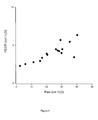
Figure 5 is a graph showing how values of intrinsic PEEP or PEEPi increases during increasing levels of mechanical ventilation (airway pressure Paw) when the patient breathes against a high inspiratory and expiratory resistive load; the graph ofFigure 5 results from the same recordings as the graph ofFigure 4 . - As described hereinabove, the concept of air-trapping relates to a quantity of air penetrating the lungs of a patient larger than the quantity of air leaving the patient's lungs. Air-trapping induced by mechanical ventilation actually worsens contractility of the inspiratory muscles due to dynamic hyperinflation until a level where weakness of the inspiratory muscles and added mechanical ventilation reach an equilibrium causing inspiratory (Vins) and expiratory (Vexp) volumes to match.
- When mechanical ventilation is removed in the presence of air-trapping, the patient has difficulty to inhale due to lost mechanical ventilation and weak inspiratory muscles. However, due to extra stored energy i.e. increased elastic recoil in the inspiratory muscles due to air-trapping, the patient has no difficulty to generate force to exhale.
- Accordingly, air-trapping during mechanical ventilation should hence result in similar inspiratory (Vins) and expiratory (Vexp) volumes during breaths with mechanical ventilation, whereas inspiratory volumes (Vins) are smaller than expiratory volumes (Vexp) during the first breaths after mechanical ventilation has been removed. When the lungs are not trapping air, the inspiratory (Vins) and expiratory (Vexp) volumes should be similar for breaths both with mechanical ventilation and without mechanical ventilation. With these concepts in mind,
Figure 1 of the appended drawings illustrates adevice 100 for determining dynamic hyperinflation during mechanical ventilation of a spontaneously breathing patient. - The
device 100 ofFigure 1 comprises asensor 101 of inspiratory (Vins) and expiratory (Vexp) volumes of apatient 102. As a non-limitative example, thesensor 101 may comprise a pneumotachograph or any other suitable sensor. Thesensor 101 is connected to the patient's airways to detect the inspiratory (Vins) and expiratory (Vexp) volumes. - A
calculator 103 is responsive to the inspiratory (Vins) and expiratory (Vexp) volumes detected by thesensor 101 to calculate a difference between the detected inspiratory (Vins) and expiratory (Vexp) volumes of the patient. - An
indicator 104 is responsive to the difference between the detected inspiratory (Vins) and expiratory (Vexp) volumes of the patient, for example the ratio Vins/Vexp, to indicate dynamic hyperinflation. - A
controller 105 is connected to thesensor 101, thecalculator 103 and amechanical ventilator 106 providing mechanical ventilation to thepatient 102. - A method 200 (
Figure 2 ) for determining dynamic hyperinflation during mechanical ventilation of a spontaneously breathing patient using the device ofFigure 1 will now be described with reference both toFigures 1 and2 . - The controller 105 (
Figure 1 ) controls the mechanical ventilator 106 (Figure 1 ) to remove mechanical ventilation of the patient 102 (Figure 1 ) during one (1) breath of the patient 102 (Figure 1 ). - The controller 105 (
Figure 1 ) controls the sensor 101 (Figure 1 ), for example a pneumotachograph, to measure: - - the volume (Inspiratory volume Vins) inhaled by the patient 102 (
Figure 1 ) during the one (1) breath during which mechanical ventilation of the patient 102 (Figure 1 ) by the mechanical ventilator 106 (Figure 1 ) is removed; and - - the volume (Expiratory volume Vexp) exhaled by the patient 102 (
Figure 1 ) during the one (1) breath during which mechanical ventilation of the patient 102 (Figure 1 ) by the mechanical ventilator 106 (Figure 1 ) is removed. - For that purpose, the sensor 101 (
Figure 1 ) is connected to the airways of the patient 102 (Figure 1 ). - The controller 105 (
Figure 1 ) also commands the calculator 103 (Figure 1 ) to calculate a difference between the inspiratory volume (Vins) and the expiratory volume (Vexp) as measured by the sensor 101 (Figure 1 ) during the one (1) breath during which mechanical ventilation of the patient 102 (Figure 1 ) by the mechanical ventilator 106 (Figure 1 ) is removed. The calculated difference can be expressed either in absolute (for example a mathematical difference between Vins and Vexp) or relative (for example a ratio between Vins and Vexp) terms. - More specifically, for the one (1) breath without mechanical ventilation from the mechanical ventilator 106 (
Figure 1 ), thecalculator 103 calculates the difference between the inspiratory volume (Vins) and the expiratory volume (Vexp) as measured by the sensor 101 (Figure 1 ), for example a ratio (Vins/Vexp) between these inspiratory (Vins) and expiratory (Vexp) volumes as measured by thesensor 101 during the one (1) breath during which mechanical ventilation of the patient 102 (Figure 1 ) by the mechanical ventilator 106 (Figure 1 ) is removed. - If the ratio (Vins/Vexp) is close to 1 this suggests that the
patient 102 is able to exhale the same amount of air as was inhaled during the one (1) breath without mechanical ventilation, suggesting that air-trapping due to the mechanical ventilator 106 (Figure 1 ) does not have a major impact and that dynamic hyperinflation induced by mechanical ventilation is not present. - However, if the ratio (Vins/Vexp) becomes close to 0, this indicates that the patient 102 (
Figure 1 ) has considerable problems related to inspiration relative to expiration and that the mechanical ventilator 102 (Figure 1 ) induces air-trapping in the lungs of the patient 102 (Figure 1 ) and therefore dynamic hyperinflation. - An indicator 104 (
Figure 1 ) is responsive to the ratio (Vins/Vexp) from the calculator 103 (Figure 1 ) to indicate dynamic hyperinflation of the patient. - For example, the indicator 104 (
Figure 1 ) may produce a light signal going from e.g. green if the ratio (Vins/Vexp) is close to 1 to indicate that dynamic hyperinflation is not present and change towards e.g. red if the ratio (Vins/Vexp) is close to 0 to indicate that dynamic hyperinflation is present. - Also, the ratio (Vins/Vexp) could be used to guide conventional titration of external PEEP, or in combination with previous neural PEEP titration methods (
US Published Patent Applications 2005/0211246 and2003/0226565 ). -
Figure 3 represents graphs showing volume and airway pressure (Paw) over time during breaths with mechanical ventilation and breaths without mechanical ventilation. An example of segments where inspiratory (Vins) and expiratory (Vexp) volumes are measured during the one (1) breath during which mechanical ventilation of the patient 102 (Figure 1 ) by the mechanical ventilator 106 (Figure 1 ) is removed, are indicated by vertical lines. - In the graph of
Figure 4 , the points show how the ratio (Vins/Vexp) decreases with increasing levels of mechanical ventilation of the patient 102 (Figure 1 ) by the mechanical ventilator 106 (Figure 1 ) when thepatient 102 breathes against a high inspiratory and expiratory resistive load. - In the graph of
Figure 5 , the points show how conventional PEEPi values increase with increasing levels of mechanical ventilation of the patient 102 (Figure 1 ) by the mechanical ventilator 106 (Figure 1 ) when thepatient 102 breathes against a high inspiratory and expiratory resistive load (same recordings as inFigure 4 ). - The sensor 101 (
Figure 1 ), for example a pneumotachograph, may measure duringoperation 202 the inspiratory volume (Vins) and the expiratory volume (Vexp) during a plurality of successive or non successive singles breaths during which mechanical ventilation of the patient 102 (Figure 1 ) by the mechanical ventilator 106 (Figure 1 ) is removed. The calculator 103 (Figure 1 ) then compute the ratio (Vins/Vexp) for example as an average of the ratios (Vins/Vexp) calculated from the inspiratory (Vins) and expiratory (Vexp) volumes measured by thesensor 101 during the respective single breaths without mechanical ventilation. - Also, the above described method 200 (
Figure 2 ) for determining dynamic hyperinflation during mechanical ventilation of a spontaneously breathing patient can be implemented at any given level of mechanical ventilation delivered by the mechanical ventilator 106 (Figure 1 ) in any type of mechanical ventilation mode.
Claims (14)
- A device (100) adapted to determine dynamic hyperinflation during mechanical ventilation of a spontaneously breathing patient (102), comprising:a controller (105) configured to remove mechanical ventilation during one breath of the patient (102);a sensor (101) configured to detect inspiratory and expiratory volumes of the patient (102) during said one breath;a calculator (103) configured to calculate a difference between the inspiratory and expiratory volumes sensed during said one breath; andan indicator (104) responsive to the calculated difference and configured to indicate dynamic hyperinflation of the patient's lungs.
- A device (100) adapted to determine dynamic hyperinflation as defined in claim 1, wherein the sensor (101) is connected to the patient's airways so as to measure, as the inspiratory volume, a volume inhaled by the patient during said one breath during which mechanical ventilation is removed.
- A device (100) adapted to determine dynamic hyperinflation as defined in claim 1, wherein the sensor (101) is connected to the patient's airways so as to measure, as the expiratory volume, a volume exhaled by the patient during said one breath during which mechanical ventilation is removed.
- A device (100) adapted to determine dynamic hyperinflation as defined in claim 1, wherein the calculator (101) of the difference calculates a ratio Vins/Vexp between the inspiratory volume Vins and the expiratory volume Vexp measured during said one breath.
- A device (100) adapted to determine dynamic hyperinflation as defined in claim 4, wherein the indicator (104) indicates that dynamic hyperinflation is not present when the ratio Vins/Vexp is close to 1 and indicates that dynamic hyperinflation is present when the ratio Vins/Vexp is close to 0.
- A device (100) adapted to determine dynamic hyperinflation as defined in claim 1, wherein the sensor (101) measures the inspiratory and expiratory volumes during a plurality of successive or non successive single breaths during which mechanical ventilation of the patient (102) is removed, and wherein the calculator (103) of the difference calculates a ratio Vins/Vexp from the inspiratory volumes Vins and the expiratory volumes (Vexp) measured during the plurality of single breaths.
- A device adapted to determine dynamic hyperinflation as defined in claim 1, wherein the controller (105) is connected to:- a mechanical ventilator (106) providing mechanical ventilation of the patient (102) to control the mechanical ventilator (106) to remove the mechanical ventilation during said one breath;- the sensor (101) of inspiratory and expiratory volumes to control said sensor (101) to measure the inspiratory and expiratory volumes during said one breath; and- the calculator (103) of the difference to control said calculator (103) to calculate the difference between the inspiratory and expiratory volumes measured during said one breath.
- A device adapted to determine dynamic hyperinflation as defined in claim 1, wherein the controller (105) controls the removal of mechanical ventilation during said one breath of the patient to maintain a level of positive pressure in the patient's airways during said one breath.
- A method (200) for determining dynamic hyperinflation during mechanical ventilation of a spontaneously breathing patient, comprising:removing mechanical ventilation during one breath (201) of the patient;measuring inspiratory and expiratory volumes (202) of the patient during said one breath;calculating a difference between the inspiratory and expiratory volumes measured during said one breath (203); andindicating dynamic hyperinflation (204) of the patient's lungs in relation to the calculated difference.
- A method (200) for determining dynamic hyperinflation as defined in claim 9, wherein measuring the inspiratory volume (202) comprises measuring a volume inhaled by the patient during said one breath during which mechanical ventilation is removed and/or measuring the expiratory volume (202) comprises measuring an expiratory volume exhaled by the patient during said one breath during which mechanical ventilation is removed.
- A method (200) for determining dynamic hyperinflation as defined in claim 9, wherein calculating the difference (203) comprises calculating a ratio Vins/Vexp between the inspiratory volume Vins and the expiratory volume Vexp measured during said one breath.
- A method (200) for determining dynamic hyperinflation as defined in claim 11, wherein indicating dynamic hyperinflation (204) comprises indicating that dynamic hyperinflation is not present when the ratio Vins/Vexp is close to 1 and indicating that dynamic hyperinflation is present when the ratio Vins/Vexp is close to 0.
- A method (200) for determining dynamic hyperinflation as defined in claim 9, wherein measuring the inspiratory and expiratory volumes (202) comprise measuring the inspiratory and expiratory volumes during a plurality of successive or non successive singles breaths during which mechanical ventilation of the patient is removed, and wherein calculating the difference (203) comprises calculating a ratio Vins/Vexp from the inspiratory volumes Vins and the expiratory volumes Vexp measured during said plurality of single breath.
- A method (200) for determining dynamic hyperinflation as defined in claim 9, wherein removing mechanical ventilation during one breath (201) of the patient maintains a level of positive pressure in the patient's airways during said one breath.
Applications Claiming Priority (2)
| Application Number | Priority Date | Filing Date | Title |
|---|---|---|---|
| US19397409P | 2009-01-14 | 2009-01-14 | |
| PCT/CA2010/000017 WO2010081214A1 (en) | 2009-01-14 | 2010-01-07 | Detection of dynamic hyperinflation in spontaneously breathing mechanically ventilated patients |
Publications (3)
| Publication Number | Publication Date |
|---|---|
| EP2375977A1 EP2375977A1 (en) | 2011-10-19 |
| EP2375977A4 EP2375977A4 (en) | 2013-11-20 |
| EP2375977B1 true EP2375977B1 (en) | 2014-12-24 |
Family
ID=42339355
Family Applications (1)
| Application Number | Title | Priority Date | Filing Date |
|---|---|---|---|
| EP10730988.2A Active EP2375977B1 (en) | 2009-01-14 | 2010-01-07 | Detection of dynamic hyperinflation in spontaneously breathing mechanically ventilated patients |
Country Status (3)
| Country | Link |
|---|---|
| US (1) | US9308338B2 (en) |
| EP (1) | EP2375977B1 (en) |
| WO (1) | WO2010081214A1 (en) |
Families Citing this family (3)
| Publication number | Priority date | Publication date | Assignee | Title |
|---|---|---|---|---|
| JP6396316B2 (en) * | 2012-12-13 | 2018-09-26 | コーニンクレッカ フィリップス エヌ ヴェKoninklijke Philips N.V. | Hand pressure support system for treating hyperinflation |
| EP3073916A1 (en) * | 2013-11-26 | 2016-10-05 | Cardiac Pacemakers, Inc. | Detection of chronic obstructive pulmonary disease exacerbations from breathing patterns |
| JP6480598B2 (en) | 2015-04-02 | 2019-03-13 | ヒル−ロム サービシーズ プライヴェート リミテッド | Respirator manifold |
Family Cites Families (9)
| Publication number | Priority date | Publication date | Assignee | Title |
|---|---|---|---|---|
| US4693256A (en) * | 1982-06-28 | 1987-09-15 | Sherwood Medical Company | Respiratory device |
| US5456264A (en) * | 1994-03-31 | 1995-10-10 | Universite Laval | Accuracy of breath-by-breath analysis of flow volume loop in identifying flow-limited breathing cycles in patients |
| GB9525994D0 (en) * | 1995-12-20 | 1996-02-21 | Univ Manitoba | Improvements in delivery of assist modes of mechanical ventilation |
| CA2239673A1 (en) | 1998-06-04 | 1999-12-04 | Christer Sinderby | Automatic adjustment of applied levels of ventilatory support and extrinsic peep by closed-loop control of neuro-ventilatory efficiency |
| US7472702B2 (en) | 2004-03-25 | 2009-01-06 | Maquet Critical Care Ab | Method and device responsive to diaphragmatic activity for adjusting positive pressure assist during expiration |
| JP5053083B2 (en) * | 2004-06-24 | 2012-10-17 | コンヴァージェント エンジニアリング インコーポレイティッド | Method and apparatus for non-invasive prediction of positive end expiratory pressure (PEEPi) in a patient receiving ventilator support |
| US7625345B2 (en) * | 2005-03-14 | 2009-12-01 | Welch Allyn, Inc. | Motivational spirometry system and method |
| WO2006127573A2 (en) * | 2005-05-20 | 2006-11-30 | Vivometrics, Inc. | Methods and systems for determining dynamic hyperinflation |
| US20070142742A1 (en) * | 2005-07-13 | 2007-06-21 | Pulmonx | Methods and systems for segmental lung diagnostics |
-
2010
- 2010-01-07 WO PCT/CA2010/000017 patent/WO2010081214A1/en not_active Ceased
- 2010-01-07 EP EP10730988.2A patent/EP2375977B1/en active Active
- 2010-01-07 US US13/143,666 patent/US9308338B2/en active Active
Also Published As
| Publication number | Publication date |
|---|---|
| EP2375977A4 (en) | 2013-11-20 |
| WO2010081214A8 (en) | 2010-09-23 |
| EP2375977A1 (en) | 2011-10-19 |
| US20120118290A1 (en) | 2012-05-17 |
| WO2010081214A1 (en) | 2010-07-22 |
| US9308338B2 (en) | 2016-04-12 |
Similar Documents
| Publication | Publication Date | Title |
|---|---|---|
| US20200129714A1 (en) | Methods and systems for adaptive base flow | |
| US9302061B2 (en) | Event-based delay detection and control of networked systems in medical ventilation | |
| EP2533837B1 (en) | Leak determination in a breathing assistance system | |
| US20220409836A1 (en) | Systems and methods for respiratory effort detection utilizing signal distortion | |
| US8603003B2 (en) | Trachea pressure determination method and device | |
| EP2923641B1 (en) | A breathing apparatus control unit and software for determination of a change in transpulmonary pressure | |
| US8561612B2 (en) | Method and system for monitoring patient's breathing action response to changes in a ventilator applied breathing support | |
| US10137266B2 (en) | Patient-ventilator dyssynchrony detection | |
| US7722546B2 (en) | Method and device for carrying out a signal-processing viewing of a measurement signal that is correlated to the respiratory activity of an individual | |
| US8720441B2 (en) | Determining patient-ventilator breath contribution index in spontaneously breathing, mechanically ventilated patients | |
| US10765822B2 (en) | Endotracheal tube extubation detection | |
| US10898671B2 (en) | Method and device for the adaptive regulation of a positive end-expiratory pressure (PEEP) | |
| US20230364369A1 (en) | Systems and methods for automatic cycling or cycling detection | |
| CN108513540B (en) | Methods, systems and software for protective ventilation | |
| GB2077444A (en) | Determining at least two parameters of a patient's respiratory system | |
| WO2012089093A1 (en) | Method and device for detecting blockage of breathing apparatus | |
| CN103182121A (en) | Pressure trigger control method for breathing machine | |
| CN112839696A (en) | Breath recognition method and device, ventilation equipment, and storage medium | |
| US9308338B2 (en) | Detection of dynamic hyperinflation in spontaneously breathing mechanically ventilated patients | |
| US6974418B1 (en) | Automatic calibration of blood volume status indicators | |
| CN116438609B (en) | Medical ventilation equipment and ventilation monitoring methods | |
| US20240335631A1 (en) | Respiration monitoring method and respiration monitoring apparatus | |
| US20240277254A1 (en) | Systems and methods for detection of positive end-expiratory pressure (peep) using diaphragmatic ultrasound | |
| US20240100290A1 (en) | Expiratory flow control |
Legal Events
| Date | Code | Title | Description |
|---|---|---|---|
| PUAI | Public reference made under article 153(3) epc to a published international application that has entered the european phase |
Free format text: ORIGINAL CODE: 0009012 |
|
| 17P | Request for examination filed |
Effective date: 20110714 |
|
| AK | Designated contracting states |
Kind code of ref document: A1 Designated state(s): AT BE BG CH CY CZ DE DK EE ES FI FR GB GR HR HU IE IS IT LI LT LU LV MC MK MT NL NO PL PT RO SE SI SK SM TR |
|
| RAP1 | Party data changed (applicant data changed or rights of an application transferred) |
Owner name: ST. MICHAEL'S HOSPITAL |
|
| DAX | Request for extension of the european patent (deleted) | ||
| RIC1 | Information provided on ipc code assigned before grant |
Ipc: A61M 16/00 20060101ALI20131008BHEP Ipc: A61B 5/091 20060101AFI20131008BHEP |
|
| A4 | Supplementary search report drawn up and despatched |
Effective date: 20131017 |
|
| GRAP | Despatch of communication of intention to grant a patent |
Free format text: ORIGINAL CODE: EPIDOSNIGR1 |
|
| INTG | Intention to grant announced |
Effective date: 20140701 |
|
| GRAS | Grant fee paid |
Free format text: ORIGINAL CODE: EPIDOSNIGR3 |
|
| GRAA | (expected) grant |
Free format text: ORIGINAL CODE: 0009210 |
|
| AK | Designated contracting states |
Kind code of ref document: B1 Designated state(s): AT BE BG CH CY CZ DE DK EE ES FI FR GB GR HR HU IE IS IT LI LT LU LV MC MK MT NL NO PL PT RO SE SI SK SM TR |
|
| REG | Reference to a national code |
Ref country code: GB Ref legal event code: FG4D |
|
| REG | Reference to a national code |
Ref country code: CH Ref legal event code: EP |
|
| REG | Reference to a national code |
Ref country code: IE Ref legal event code: FG4D |
|
| REG | Reference to a national code |
Ref country code: AT Ref legal event code: REF Ref document number: 702706 Country of ref document: AT Kind code of ref document: T Effective date: 20150115 |
|
| REG | Reference to a national code |
Ref country code: DE Ref legal event code: R096 Ref document number: 602010021254 Country of ref document: DE Effective date: 20150212 |
|
| REG | Reference to a national code |
Ref country code: NL Ref legal event code: VDEP Effective date: 20141224 |
|
| PG25 | Lapsed in a contracting state [announced via postgrant information from national office to epo] |
Ref country code: NO Free format text: LAPSE BECAUSE OF FAILURE TO SUBMIT A TRANSLATION OF THE DESCRIPTION OR TO PAY THE FEE WITHIN THE PRESCRIBED TIME-LIMIT Effective date: 20150324 Ref country code: FI Free format text: LAPSE BECAUSE OF FAILURE TO SUBMIT A TRANSLATION OF THE DESCRIPTION OR TO PAY THE FEE WITHIN THE PRESCRIBED TIME-LIMIT Effective date: 20141224 Ref country code: LT Free format text: LAPSE BECAUSE OF FAILURE TO SUBMIT A TRANSLATION OF THE DESCRIPTION OR TO PAY THE FEE WITHIN THE PRESCRIBED TIME-LIMIT Effective date: 20141224 |
|
| REG | Reference to a national code |
Ref country code: LT Ref legal event code: MG4D |
|
| PG25 | Lapsed in a contracting state [announced via postgrant information from national office to epo] |
Ref country code: SE Free format text: LAPSE BECAUSE OF FAILURE TO SUBMIT A TRANSLATION OF THE DESCRIPTION OR TO PAY THE FEE WITHIN THE PRESCRIBED TIME-LIMIT Effective date: 20141224 Ref country code: GR Free format text: LAPSE BECAUSE OF FAILURE TO SUBMIT A TRANSLATION OF THE DESCRIPTION OR TO PAY THE FEE WITHIN THE PRESCRIBED TIME-LIMIT Effective date: 20150325 Ref country code: LV Free format text: LAPSE BECAUSE OF FAILURE TO SUBMIT A TRANSLATION OF THE DESCRIPTION OR TO PAY THE FEE WITHIN THE PRESCRIBED TIME-LIMIT Effective date: 20141224 Ref country code: HR Free format text: LAPSE BECAUSE OF FAILURE TO SUBMIT A TRANSLATION OF THE DESCRIPTION OR TO PAY THE FEE WITHIN THE PRESCRIBED TIME-LIMIT Effective date: 20141224 |
|
| REG | Reference to a national code |
Ref country code: AT Ref legal event code: MK05 Ref document number: 702706 Country of ref document: AT Kind code of ref document: T Effective date: 20141224 |
|
| PG25 | Lapsed in a contracting state [announced via postgrant information from national office to epo] |
Ref country code: NL Free format text: LAPSE BECAUSE OF FAILURE TO SUBMIT A TRANSLATION OF THE DESCRIPTION OR TO PAY THE FEE WITHIN THE PRESCRIBED TIME-LIMIT Effective date: 20141224 |
|
| PG25 | Lapsed in a contracting state [announced via postgrant information from national office to epo] |
Ref country code: ES Free format text: LAPSE BECAUSE OF FAILURE TO SUBMIT A TRANSLATION OF THE DESCRIPTION OR TO PAY THE FEE WITHIN THE PRESCRIBED TIME-LIMIT Effective date: 20141224 Ref country code: CZ Free format text: LAPSE BECAUSE OF FAILURE TO SUBMIT A TRANSLATION OF THE DESCRIPTION OR TO PAY THE FEE WITHIN THE PRESCRIBED TIME-LIMIT Effective date: 20141224 Ref country code: RO Free format text: LAPSE BECAUSE OF FAILURE TO SUBMIT A TRANSLATION OF THE DESCRIPTION OR TO PAY THE FEE WITHIN THE PRESCRIBED TIME-LIMIT Effective date: 20141224 Ref country code: EE Free format text: LAPSE BECAUSE OF FAILURE TO SUBMIT A TRANSLATION OF THE DESCRIPTION OR TO PAY THE FEE WITHIN THE PRESCRIBED TIME-LIMIT Effective date: 20141224 Ref country code: SK Free format text: LAPSE BECAUSE OF FAILURE TO SUBMIT A TRANSLATION OF THE DESCRIPTION OR TO PAY THE FEE WITHIN THE PRESCRIBED TIME-LIMIT Effective date: 20141224 |
|
| REG | Reference to a national code |
Ref country code: CH Ref legal event code: PL |
|
| PG25 | Lapsed in a contracting state [announced via postgrant information from national office to epo] |
Ref country code: PL Free format text: LAPSE BECAUSE OF FAILURE TO SUBMIT A TRANSLATION OF THE DESCRIPTION OR TO PAY THE FEE WITHIN THE PRESCRIBED TIME-LIMIT Effective date: 20141224 Ref country code: IS Free format text: LAPSE BECAUSE OF FAILURE TO SUBMIT A TRANSLATION OF THE DESCRIPTION OR TO PAY THE FEE WITHIN THE PRESCRIBED TIME-LIMIT Effective date: 20150424 Ref country code: LU Free format text: LAPSE BECAUSE OF FAILURE TO SUBMIT A TRANSLATION OF THE DESCRIPTION OR TO PAY THE FEE WITHIN THE PRESCRIBED TIME-LIMIT Effective date: 20150107 Ref country code: AT Free format text: LAPSE BECAUSE OF FAILURE TO SUBMIT A TRANSLATION OF THE DESCRIPTION OR TO PAY THE FEE WITHIN THE PRESCRIBED TIME-LIMIT Effective date: 20141224 |
|
| REG | Reference to a national code |
Ref country code: DE Ref legal event code: R097 Ref document number: 602010021254 Country of ref document: DE |
|
| PG25 | Lapsed in a contracting state [announced via postgrant information from national office to epo] |
Ref country code: MC Free format text: LAPSE BECAUSE OF FAILURE TO SUBMIT A TRANSLATION OF THE DESCRIPTION OR TO PAY THE FEE WITHIN THE PRESCRIBED TIME-LIMIT Effective date: 20141224 |
|
| PG25 | Lapsed in a contracting state [announced via postgrant information from national office to epo] |
Ref country code: LI Free format text: LAPSE BECAUSE OF NON-PAYMENT OF DUE FEES Effective date: 20150131 Ref country code: DK Free format text: LAPSE BECAUSE OF FAILURE TO SUBMIT A TRANSLATION OF THE DESCRIPTION OR TO PAY THE FEE WITHIN THE PRESCRIBED TIME-LIMIT Effective date: 20141224 Ref country code: CH Free format text: LAPSE BECAUSE OF NON-PAYMENT OF DUE FEES Effective date: 20150131 |
|
| PLBE | No opposition filed within time limit |
Free format text: ORIGINAL CODE: 0009261 |
|
| REG | Reference to a national code |
Ref country code: IE Ref legal event code: MM4A |
|
| STAA | Information on the status of an ep patent application or granted ep patent |
Free format text: STATUS: NO OPPOSITION FILED WITHIN TIME LIMIT |
|
| GBPC | Gb: european patent ceased through non-payment of renewal fee |
Effective date: 20150324 |
|
| 26N | No opposition filed |
Effective date: 20150925 |
|
| PG25 | Lapsed in a contracting state [announced via postgrant information from national office to epo] |
Ref country code: IT Free format text: LAPSE BECAUSE OF FAILURE TO SUBMIT A TRANSLATION OF THE DESCRIPTION OR TO PAY THE FEE WITHIN THE PRESCRIBED TIME-LIMIT Effective date: 20141224 |
|
| PG25 | Lapsed in a contracting state [announced via postgrant information from national office to epo] |
Ref country code: IE Free format text: LAPSE BECAUSE OF NON-PAYMENT OF DUE FEES Effective date: 20150107 Ref country code: GB Free format text: LAPSE BECAUSE OF NON-PAYMENT OF DUE FEES Effective date: 20150324 |
|
| REG | Reference to a national code |
Ref country code: FR Ref legal event code: PLFP Year of fee payment: 7 |
|
| PG25 | Lapsed in a contracting state [announced via postgrant information from national office to epo] |
Ref country code: SI Free format text: LAPSE BECAUSE OF FAILURE TO SUBMIT A TRANSLATION OF THE DESCRIPTION OR TO PAY THE FEE WITHIN THE PRESCRIBED TIME-LIMIT Effective date: 20141224 |
|
| PG25 | Lapsed in a contracting state [announced via postgrant information from national office to epo] |
Ref country code: BE Free format text: LAPSE BECAUSE OF FAILURE TO SUBMIT A TRANSLATION OF THE DESCRIPTION OR TO PAY THE FEE WITHIN THE PRESCRIBED TIME-LIMIT Effective date: 20141224 |
|
| PG25 | Lapsed in a contracting state [announced via postgrant information from national office to epo] |
Ref country code: MT Free format text: LAPSE BECAUSE OF FAILURE TO SUBMIT A TRANSLATION OF THE DESCRIPTION OR TO PAY THE FEE WITHIN THE PRESCRIBED TIME-LIMIT Effective date: 20141224 |
|
| REG | Reference to a national code |
Ref country code: FR Ref legal event code: PLFP Year of fee payment: 8 |
|
| PG25 | Lapsed in a contracting state [announced via postgrant information from national office to epo] |
Ref country code: HU Free format text: LAPSE BECAUSE OF FAILURE TO SUBMIT A TRANSLATION OF THE DESCRIPTION OR TO PAY THE FEE WITHIN THE PRESCRIBED TIME-LIMIT; INVALID AB INITIO Effective date: 20100107 Ref country code: SM Free format text: LAPSE BECAUSE OF FAILURE TO SUBMIT A TRANSLATION OF THE DESCRIPTION OR TO PAY THE FEE WITHIN THE PRESCRIBED TIME-LIMIT Effective date: 20141224 Ref country code: BG Free format text: LAPSE BECAUSE OF FAILURE TO SUBMIT A TRANSLATION OF THE DESCRIPTION OR TO PAY THE FEE WITHIN THE PRESCRIBED TIME-LIMIT Effective date: 20141224 |
|
| PG25 | Lapsed in a contracting state [announced via postgrant information from national office to epo] |
Ref country code: CY Free format text: LAPSE BECAUSE OF FAILURE TO SUBMIT A TRANSLATION OF THE DESCRIPTION OR TO PAY THE FEE WITHIN THE PRESCRIBED TIME-LIMIT Effective date: 20141224 |
|
| PG25 | Lapsed in a contracting state [announced via postgrant information from national office to epo] |
Ref country code: PT Free format text: LAPSE BECAUSE OF FAILURE TO SUBMIT A TRANSLATION OF THE DESCRIPTION OR TO PAY THE FEE WITHIN THE PRESCRIBED TIME-LIMIT Effective date: 20150424 |
|
| PG25 | Lapsed in a contracting state [announced via postgrant information from national office to epo] |
Ref country code: TR Free format text: LAPSE BECAUSE OF FAILURE TO SUBMIT A TRANSLATION OF THE DESCRIPTION OR TO PAY THE FEE WITHIN THE PRESCRIBED TIME-LIMIT Effective date: 20141224 |
|
| REG | Reference to a national code |
Ref country code: FR Ref legal event code: PLFP Year of fee payment: 9 |
|
| PG25 | Lapsed in a contracting state [announced via postgrant information from national office to epo] |
Ref country code: MK Free format text: LAPSE BECAUSE OF FAILURE TO SUBMIT A TRANSLATION OF THE DESCRIPTION OR TO PAY THE FEE WITHIN THE PRESCRIBED TIME-LIMIT Effective date: 20141224 |
|
| P01 | Opt-out of the competence of the unified patent court (upc) registered |
Effective date: 20230601 |
|
| PGFP | Annual fee paid to national office [announced via postgrant information from national office to epo] |
Ref country code: FR Payment date: 20251217 Year of fee payment: 17 |
|
| PGFP | Annual fee paid to national office [announced via postgrant information from national office to epo] |
Ref country code: DE Payment date: 20251217 Year of fee payment: 17 |