EP2375488A1 - Planar antenna and handheld device - Google Patents
Planar antenna and handheld device Download PDFInfo
- Publication number
- EP2375488A1 EP2375488A1 EP11159692A EP11159692A EP2375488A1 EP 2375488 A1 EP2375488 A1 EP 2375488A1 EP 11159692 A EP11159692 A EP 11159692A EP 11159692 A EP11159692 A EP 11159692A EP 2375488 A1 EP2375488 A1 EP 2375488A1
- Authority
- EP
- European Patent Office
- Prior art keywords
- antenna
- point
- feed point
- planar
- planar antenna
- Prior art date
- Legal status (The legal status is an assumption and is not a legal conclusion. Google has not performed a legal analysis and makes no representation as to the accuracy of the status listed.)
- Granted
Links
Images





Classifications
-
- H—ELECTRICITY
- H01—ELECTRIC ELEMENTS
- H01Q—ANTENNAS, i.e. RADIO AERIALS
- H01Q1/00—Details of, or arrangements associated with, antennas
- H01Q1/12—Supports; Mounting means
- H01Q1/22—Supports; Mounting means by structural association with other equipment or articles
- H01Q1/24—Supports; Mounting means by structural association with other equipment or articles with receiving set
- H01Q1/241—Supports; Mounting means by structural association with other equipment or articles with receiving set used in mobile communications, e.g. GSM
- H01Q1/242—Supports; Mounting means by structural association with other equipment or articles with receiving set used in mobile communications, e.g. GSM specially adapted for hand-held use
- H01Q1/243—Supports; Mounting means by structural association with other equipment or articles with receiving set used in mobile communications, e.g. GSM specially adapted for hand-held use with built-in antennas
-
- H—ELECTRICITY
- H01—ELECTRIC ELEMENTS
- H01Q—ANTENNAS, i.e. RADIO AERIALS
- H01Q1/00—Details of, or arrangements associated with, antennas
- H01Q1/52—Means for reducing coupling between antennas; Means for reducing coupling between an antenna and another structure
- H01Q1/521—Means for reducing coupling between antennas; Means for reducing coupling between an antenna and another structure reducing the coupling between adjacent antennas
-
- H—ELECTRICITY
- H01—ELECTRIC ELEMENTS
- H01Q—ANTENNAS, i.e. RADIO AERIALS
- H01Q21/00—Antenna arrays or systems
- H01Q21/28—Combinations of substantially independent non-interacting antenna units or systems
-
- H—ELECTRICITY
- H01—ELECTRIC ELEMENTS
- H01Q—ANTENNAS, i.e. RADIO AERIALS
- H01Q5/00—Arrangements for simultaneous operation of antennas on two or more different wavebands, e.g. dual-band or multi-band arrangements
- H01Q5/10—Resonant antennas
-
- H—ELECTRICITY
- H01—ELECTRIC ELEMENTS
- H01Q—ANTENNAS, i.e. RADIO AERIALS
- H01Q9/00—Electrically-short antennas having dimensions not more than twice the operating wavelength and consisting of conductive active radiating elements
- H01Q9/04—Resonant antennas
- H01Q9/30—Resonant antennas with feed to end of elongated active element, e.g. unipole
- H01Q9/42—Resonant antennas with feed to end of elongated active element, e.g. unipole with folded element, the folded parts being spaced apart a small fraction of the operating wavelength
Definitions
- the subject application generally relates to a planar antenna, and more particularly, to a planar antenna of a handheld device.
- Multi-input multi-output is a term used for describing the transmission of radio signals between multiple antennas.
- MIMO refers to the use of multiple antennas respectively at a transmitter and a receiver, wherein signals are transmitted and received by the antennas at the transmitter and the receiver so that the service quality provided to each user is improved.
- the MIMO technology offers an increased frequency available ratio such that the system can transmit data more efficiently with limited wireless bandwidth.
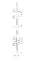
- FIG. 1 is a diagram of a conventional MIMO handheld device.
- FIG. 2 is a diagram illustrating the signal quality (VSWR) of a planar antenna in FIG. 1 .
- a handheld device 100 adopts two planar antennas 110 and 120.
- the planar antenna 110 has a feed point F110 and a ground point G110.
- the planar antenna 120 has a feed point F120 and a ground point G120. Because the planar antennas 110 and 120 have similar operating frequencies, signals transmitted and received by the planar antennas 110 and 120 may interfere with each other. The interference cannot be effectively eliminated (as shown in FIG. 2 ) even when the planar antennas 110 and 120 are respectively disposed at two different sides of the handheld device 100.
- the curve 131 indicates the transceiving quality of the planar antenna 110
- the curve 132 indicates the transceiving quality of the planar antenna 120
- the curve 133 indicates the situation of signal interference.
- a planar antenna requires a clearance area. If two planar antennas are respectively disposed at two different sides of a handheld device, a greater total clearance area is required by the two planar antennas and which is disadvantageous to the circuit layout of the handheld device. Besides, there may not be enough space for respectively disposing two planar antennas at two different sides of a handheld device. The closer the two planar antennas are, the more serious the problem of signal interference is. Moreover, the problem of signal interference is aggravated if three or more antennas are disposed in a handheld device.
- the subject application is directed to a planar antenna with improved performance in radio signal transceiving.
- the subject application is also directed to a handheld device, wherein two antennas are integrated into one antenna so that noise interference to the antenna is reduced.
- the subject application provides a planar antenna including a connecting portion, a first antenna portion, and a second antenna portion.
- the first antenna portion comprises a first feed point and a first ground point. A first end of the first antenna portion is connected to a first end of the connecting portion.
- the first feed point is located between the first end and a second end of the first antenna portion.
- the first ground point is located between the first feed point and the first end of the first antenna portion.
- the second antenna portion comprises a second feed point and a second ground point.
- a first end of the second antenna portion is connected to a second end of the connecting portion.
- the second feed point is located between the first end and a second end of the second antenna portion.
- the second ground point is located between the second feed point and the first end of the first antenna portion.
- the connecting portion sets with a width, and the impedance of the connecting portion is in a positive correlation to the width thereof.
- the connecting portion sets with a length, and the impedance of the connecting portion is in a negative correlation to the length thereof.
- the first antenna portion includes a radiating portion and an extending portion, wherein the extending portion is extended outwards from the radiating portion, the first feed point and the first ground point are disposed at the extending portion, and a center frequency of the first antenna portion is determined according to the distance between the first feed point and the first ground point.
- the second antenna portion includes a radiating portion, a first extending portion, and a second extending portion, wherein the first extending portion and the second extending portion are respectively extended outwards from the radiating portion, the second feed point and the second ground point are respectively disposed at the first extending portion and the second extending portion, and a center frequency of the second antenna portion is determined according to a signal path length between the second feed point and the second ground point.
- the first antenna portion includes a first radiating portion
- the second antenna portion includes a second radiating portion.
- the frequency of the first antenna portion is determined according to the length of the first radiating portion
- the frequency of the second antenna portion is determined according to the length of the second radiating portion, wherein the frequency of the first antenna portion and the frequency of the second antenna portion are substantially with fundamental-harmonic relationships.
- the connecting portion, the first antenna portion, and the second antenna portion are made of a flexible conductive material, and the planar antenna is flexibly disposed at a fixing device to present a three-dimensional (3D) structure.
- the subject application also provides a handheld device including a planar antenna and a system ground plane.
- the planar antenna comprises a first feed point, a first ground point, a second feed point, and a second ground point.
- the first ground point and the second ground point are located between the first feed point and the second feed point.
- the system ground plane is electrically connected to the first feed point, the first ground point, the second feed point, and the second ground point.
- two antennas are integrated into one planar antenna, and the planar antenna comprises two feed points and two ground points, wherein the ground points are located between the feed points.
- the planar antenna comprises two feed points and two ground points, wherein the ground points are located between the feed points.
- FIG. 1 is a diagram of a conventional multi-input multi-output (MIMO) handheld device.
- MIMO multi-input multi-output
- FIG. 2 is a diagram illustrating the signal quality of a planar antenna in FIG. 1 .
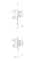
- FIG. 3 is a diagram of two planar antennas according to a first embodiment of the subject application.
- FIG. 4 is a diagram of a planar antenna according to the first embodiment of the subject application.
- FIG. 5 is a diagram of a planar antenna according to a second embodiment of the subject application.
- FIG. 6 is a diagram of a planar antenna according to a third embodiment of the subject application.
- FIG. 7 is a diagram of a planar antenna according to a fourth embodiment of the subject application.
- FIG. 8 is a diagram of a planar antenna according to a fifth embodiment of the subject application.
- FIG. 9 is a diagram of a planar antenna according to a sixth embodiment of the subject application.
- FIG. 10 is a diagram of a planar antenna according to a seventh embodiment of the subject application.
- FIG. 11 is a diagram illustrating the disposition on both sides of a planar antenna according to the seventh embodiment of the subject application.
- FIG. 12 is a diagram illustrating the signal quality (VSWR) of the planar antenna in FIG. 10 .
- two planar antennas are integrated into one planar antenna so that the total clearance area of the planar antenna is reduced and interference between two planar antennas is avoided.
- FIG. 3 is a diagram of two planar antennas according to a first embodiment of the subject application.
- the antenna portion 20 comprises a radiating portion 201 and an extending portion 202.
- the extending portion 202 is extended outwards from the radiating portion 201.
- the extending portion 202 comprises a feed point F1 and a ground point G1.
- the antenna portion 30 includes a radiating portion 301 and an extending portion 302.
- the extending portion 302 is extended outwards from the radiating portion 301.
- the extending portion 302 comprises a feed point F2 and a ground point G2.
- the ground points G1 and G2 are respectively connected to a ground end of the system ground plane.
- the handheld device can adopt a MIMO technique.
- the handheld device may be a smart phone, a personal digital assistant (PDA), a satellite navigation device, a smart e-book, a tablet or a notebook computer, etc.
- PDA personal digital assistant
- satellite navigation device a smart e-book
- tablet or a notebook computer etc.
- FIG. 4 is a diagram of a planar antenna according to the first embodiment of the subject application.
- the planar antenna 11 is similar to two planar antennas 10.
- the planar antenna 11 further includes a connecting portion 40.
- the connecting portion 40 is connected between the antenna portion 20 and the antenna portion 30, and accordingly the ground points G1 and G2 are located between the feed points F1 and F2.
- the planar antenna 11 is integrated with a MIMO function, and which comprises two feed points and two ground points.
- the feed point F1 and the ground point G1 are considered as the signal input/output terminals of the antenna portion 20, and the feed point F2 and the ground point G2 are considered as the signal input/output terminals of the antenna portion 30.
- the handheld device can carry out wireless communication through the antenna portion 20 and/or the antenna portion 30.
- the connecting portion 40 is a conductive body connected between the antenna portions 20 and 30, and which changes the impedance between the antenna portions 20 and 30.
- those skilled in the art can adopt a connecting portion 40 of different impedance according to their actual requirement so that an impedance matching effect can be achieved.
- signal interference between antennas is reduced.
- the total clearance area required by the antenna portions 20 and 30 is also reduced compared to that required by respectively disposed antennas.
- the application of the subject application is not limited to aforementioned possible pattern.
- the planar antenna comprises at least two feed points and at least two ground points and the ground points are located between the feed points.
- the operating frequency of the antenna portion 20 may be changed by changing the length of the radiating portion 201.
- the operating frequency of the antenna portion 30 may be changed by changing the length of the radiating portion 301.
- center frequency of the antenna portion 20 may be changed by changing the distance between the feed point F1 and the ground point G1.
- center frequency of the antenna portion 30 may be changed by changing the distance between the feed point F2 and the ground point G2.
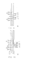
- FIG. 5 is a diagram of a planar antenna according to a second embodiment of the subject application.
- the planar antenna 12 in FIG. 5 is similar to the planar antenna 11 in FIG. 4 .
- the connecting portion 41 in FIG. 5 is wider than the connecting portion 40 in FIG. 4 . Accordingly, the impedance between the antenna portions 20 and 30 in FIG. 5 is reduced. Namely, the impedance of the connecting portion is in a positive correlation to the width thereof.
- FIG. 6 is a diagram of a planar antenna according to a third embodiment of the subject application.
- the planar antenna 13 in FIG. 6 is similar to the planar antenna 11 in FIG. 4 .
- the connecting portion 42 in FIG. 6 is shorter than the connecting portion 40 in FIG. 4 . Accordingly, the impedance between the antenna portions 20 and 30 in FIG. 6 is reduced. Namely, the impedance of the connecting portion is in a negative correlation to the length thereof.
- FIG. 7 is a diagram of a planar antenna according to a fourth embodiment of the subject application.
- the planar antenna 14 in FIG. 7 is similar to the planar antenna 11 in FIG. 4 .
- the antenna portion 31 in FIG. 7 includes a radiating portion 301 and extending portions 311 and 312.
- the feed point F2 and the ground point G2 are respectively disposed at the extending portions 311 and 312 so that signal transmission paths between the feed point F2 and the ground point G2 are increased, and the center frequency of the antenna portion 31 is also changed.
- FIG. 8 is a diagram of a planar antenna according to a fifth embodiment of the subject application.
- the planar antenna 15 in FIG. 8 is similar to the planar antenna 11 in FIG. 4 .
- the antenna portion 21 includes a radiating portion 211 and an extending portion 202.
- the antenna portion 30 includes a radiating portion 301 and an extending portion 302. It should be noted that the length of the radiating portion will affect the operating frequency of the antenna portion.
- the length of the radiating portion 211 is designed to be different from that of the radiating portion 301, so that the frequency of the antenna portion 21 and the frequency of the antenna portion 30 are with fundamental-harmonic relationships.
- the frequency of the antenna portion 21 is approximately the second harmonic mode of the fundamental mode of the antenna portion 30.
- FIG. 9 is a diagram of a planar antennas according to a sixth embodiment of the subject application.
- the planar antenna 16 in FIG. 9 is similar to the planar antenna 11 in FIG. 4 .
- the antenna portion 20 includes a radiating portion 201 and an extending portion 202.
- the antenna portion 32 includes a radiating portion 321 and an extending portion 302.
- the first end of the radiating portion 201 is connected to the connecting portion 40.
- the first end of the radiating portion 321 is connected to the connecting portion 40.
- the second end of the radiating portion 201 affects the radiation pattern of the antenna portion 20.
- the second end of the radiating portion 321 also affects the radiation pattern of the antenna portion 32.
- the second end of the radiating portion 321 is pointed to the same direction as the second end of the radiating portion 201 by changing the pattern of the radiating portion 321, so that the radiation pattern and the transceiving quality of the antenna is improved and the signal interference of the antenna is reduced.
- FIG. 10 is a diagram of a planar antenna according to a seventh embodiment of the subject application.
- the antenna portion 33 of the planar antenna 17 includes a radiating portion 331 and extending portions 332 and 333.
- the radiating portion 331 can be designed to be in an irregular shape because of different reasons (for example, to fit in the space of the handheld device or to improve signal quality, etc). This also applies to the radiating portion 221 because of similar reasons.
- FIG. 11 is a diagram illustrating the disposition on both sides of a planar antenna according to the seventh embodiment of the subject application. Referring to FIG. 10 and FIG. 11 , in the present embodiment, the fixing device is described as a base frame 50, wherein the base frame 50 has a through hole 60.
- the planar antenna 17 passes through the through hole 60 so that the antenna portion 22 and a portion of the antenna portion 33 are disposed on the first side of the base frame 50, and another portion of the antenna portion 33 is disposed on the other side of the base frame 50. Accordingly, the planar antenna 17 forms a 3D structure.
- different fixing devices may be adopted by those skilled in the art to allow the planar antenna 17 to form different 3D structures.
- FIG. 12 is a diagram illustrating the signal quality (VSWR) of the planar antenna in FIG. 10 .
- the curve 501 indicates the transceiving quality of the antenna portion 22
- the curve 502 indicates the transceiving quality of the antenna portion 33
- the curve 503 indicates the situation of signal interference, wherein the antenna portion 33 may have more than two harmonic frequencies (for example, 1G-1.2G and 2.5G-2.7G), and the center frequency of the second harmonic oscillation may be operated within the same operating bandwidth as that of the antenna portion 22 through appropriate adjustment.
- the center frequency of the second harmonic oscillation may be operated within the same operating bandwidth as that of the antenna portion 22 through appropriate adjustment.
- signal interference within the bandwidth of 2.5G-2.7G is effectively reduced.
- the transceiving quality illustrated in FIG. 12 is obviously improved compared with that illustrated in FIG. 4 .
- planar antenna described in the present disclosure can be applied by those skilled in the art to wireless communication systems adopting MIMO techniques, such as WIMAX, GPS, and 3G, etc.
- the frequency of each antenna portion in the planar antenna can be fine tuned by those skilled in the art by using a matching circuit.
- two antennas are integrated into one planar antenna comprising at least two feed points and at least two ground points, wherein the ground points are located between the feed points.
- the layout of the planar antenna is made more flexible, and signal interference to the planar antenna is reduced.
- an embodiment of the subject application may further have following advantages:
Landscapes
- Engineering & Computer Science (AREA)
- Computer Networks & Wireless Communication (AREA)
- Details Of Aerials (AREA)
- Variable-Direction Aerials And Aerial Arrays (AREA)
- Support Of Aerials (AREA)
- Waveguide Aerials (AREA)
Abstract
Description
- The subject application generally relates to a planar antenna, and more particularly, to a planar antenna of a handheld device.
- Multi-input multi-output (MIMO) is a term used for describing the transmission of radio signals between multiple antennas. In short, MIMO refers to the use of multiple antennas respectively at a transmitter and a receiver, wherein signals are transmitted and received by the antennas at the transmitter and the receiver so that the service quality provided to each user is improved. Compared to a conventional signal-antenna system, the MIMO technology offers an increased frequency available ratio such that the system can transmit data more efficiently with limited wireless bandwidth.
-
FIG. 1 is a diagram of a conventional MIMO handheld device.FIG. 2 is a diagram illustrating the signal quality (VSWR) of a planar antenna inFIG. 1 . Referring toFIG. 1 andFIG. 2 , ahandheld device 100 adopts twoplanar antennas planar antenna 110 has a feed point F110 and a ground point G110. Theplanar antenna 120 has a feed point F120 and a ground point G120. Because theplanar antennas planar antennas FIG. 2 ) even when theplanar antennas handheld device 100. InFIG. 2 , thecurve 131 indicates the transceiving quality of theplanar antenna 110, thecurve 132 indicates the transceiving quality of theplanar antenna 120, and thecurve 133 indicates the situation of signal interference. - Generally speaking, a planar antenna requires a clearance area. If two planar antennas are respectively disposed at two different sides of a handheld device, a greater total clearance area is required by the two planar antennas and which is disadvantageous to the circuit layout of the handheld device. Besides, there may not be enough space for respectively disposing two planar antennas at two different sides of a handheld device. The closer the two planar antennas are, the more serious the problem of signal interference is. Moreover, the problem of signal interference is aggravated if three or more antennas are disposed in a handheld device.
- Accordingly, the subject application is directed to a planar antenna with improved performance in radio signal transceiving.
- The subject application is also directed to a handheld device, wherein two antennas are integrated into one antenna so that noise interference to the antenna is reduced.
- The subject application provides a planar antenna including a connecting portion, a first antenna portion, and a second antenna portion. The first antenna portion comprises a first feed point and a first ground point. A first end of the first antenna portion is connected to a first end of the connecting portion. The first feed point is located between the first end and a second end of the first antenna portion. The first ground point is located between the first feed point and the first end of the first antenna portion. The second antenna portion comprises a second feed point and a second ground point. A first end of the second antenna portion is connected to a second end of the connecting portion. The second feed point is located between the first end and a second end of the second antenna portion. The second ground point is located between the second feed point and the first end of the first antenna portion.
- According to an embodiment of the subject application, the connecting portion sets with a width, and the impedance of the connecting portion is in a positive correlation to the width thereof. According to another embodiment, the connecting portion sets with a length, and the impedance of the connecting portion is in a negative correlation to the length thereof.
- According to an embodiment of the subject application, the first antenna portion includes a radiating portion and an extending portion, wherein the extending portion is extended outwards from the radiating portion, the first feed point and the first ground point are disposed at the extending portion, and a center frequency of the first antenna portion is determined according to the distance between the first feed point and the first ground point.
- According to an embodiment of the subject application, the second antenna portion includes a radiating portion, a first extending portion, and a second extending portion, wherein the first extending portion and the second extending portion are respectively extended outwards from the radiating portion, the second feed point and the second ground point are respectively disposed at the first extending portion and the second extending portion, and a center frequency of the second antenna portion is determined according to a signal path length between the second feed point and the second ground point.
- According to an embodiment of the subject application, the first antenna portion includes a first radiating portion, and the second antenna portion includes a second radiating portion. The frequency of the first antenna portion is determined according to the length of the first radiating portion, and the frequency of the second antenna portion is determined according to the length of the second radiating portion, wherein the frequency of the first antenna portion and the frequency of the second antenna portion are substantially with fundamental-harmonic relationships.
- According to an embodiment of the subject application, the connecting portion, the first antenna portion, and the second antenna portion are made of a flexible conductive material, and the planar antenna is flexibly disposed at a fixing device to present a three-dimensional (3D) structure.
- The subject application also provides a handheld device including a planar antenna and a system ground plane. The planar antenna comprises a first feed point, a first ground point, a second feed point, and a second ground point. The first ground point and the second ground point are located between the first feed point and the second feed point. The system ground plane is electrically connected to the first feed point, the first ground point, the second feed point, and the second ground point.
- As described above, in the subject application, two antennas are integrated into one planar antenna, and the planar antenna comprises two feed points and two ground points, wherein the ground points are located between the feed points. Thereby, interference between antennas is eliminated and the space disposition of the antenna is improved.
- The accompanying drawings are included to provide a further understanding of the invention, and are incorporated in and constitute a part of this specification. The drawings illustrate embodiments of the invention and, together with the description, serve to explain the principles of the invention.
-
FIG. 1 is a diagram of a conventional multi-input multi-output (MIMO) handheld device. -
FIG. 2 is a diagram illustrating the signal quality of a planar antenna inFIG. 1 . -
FIG. 3 is a diagram of two planar antennas according to a first embodiment of the subject application. -
FIG. 4 is a diagram of a planar antenna according to the first embodiment of the subject application. -
FIG. 5 is a diagram of a planar antenna according to a second embodiment of the subject application. -
FIG. 6 is a diagram of a planar antenna according to a third embodiment of the subject application. -
FIG. 7 is a diagram of a planar antenna according to a fourth embodiment of the subject application. -
FIG. 8 is a diagram of a planar antenna according to a fifth embodiment of the subject application. -
FIG. 9 is a diagram of a planar antenna according to a sixth embodiment of the subject application. -
FIG. 10 is a diagram of a planar antenna according to a seventh embodiment of the subject application. -
FIG. 11 is a diagram illustrating the disposition on both sides of a planar antenna according to the seventh embodiment of the subject application. -
FIG. 12 is a diagram illustrating the signal quality (VSWR) of the planar antenna inFIG. 10 . - In a conventional multi-input multi-output (MIMO) handheld device, signal interference between planar antennas is serious and the planar antennas are difficult to be disposed.
- In an embodiment of the subject application, two planar antennas are integrated into one planar antenna so that the total clearance area of the planar antenna is reduced and interference between two planar antennas is avoided. Reference will now be made in detail to exemplary embodiments of the subject application, examples of which are illustrated in the accompanying drawings. Wherever possible, the same reference numbers are used in the drawings and the description to refer to the same or like parts.
-
FIG. 3 is a diagram of two planar antennas according to a first embodiment of the subject application. Theantenna portion 20 comprises a radiatingportion 201 and an extendingportion 202. The extendingportion 202 is extended outwards from the radiatingportion 201. The extendingportion 202 comprises a feed point F1 and a ground point G1. Theantenna portion 30 includes a radiatingportion 301 and an extendingportion 302. The extendingportion 302 is extended outwards from the radiatingportion 301. The extendingportion 302 comprises a feed point F2 and a ground point G2. When theantenna portions - In
FIG. 3 , the closer theantenna portion 20 and theantenna portion 30 are disposed, the more serious the signal interference problem is. Accordingly, in the present embodiment, theantenna portion 20 and theantenna portion 30 are integrated together by using a connecting portion so that the layout of the antennas is improved and signal interference between antennas is effectively avoided. -
FIG. 4 is a diagram of a planar antenna according to the first embodiment of the subject application. Referring toFIG. 3 and FIG. 4 , theplanar antenna 11 is similar to twoplanar antennas 10. However, theplanar antenna 11 further includes a connectingportion 40. The connectingportion 40 is connected between theantenna portion 20 and theantenna portion 30, and accordingly the ground points G1 and G2 are located between the feed points F1 and F2. - The
planar antenna 11 is integrated with a MIMO function, and which comprises two feed points and two ground points. The feed point F1 and the ground point G1 are considered as the signal input/output terminals of theantenna portion 20, and the feed point F2 and the ground point G2 are considered as the signal input/output terminals of theantenna portion 30. In other words, the handheld device can carry out wireless communication through theantenna portion 20 and/or theantenna portion 30. - It should be noted that the connecting
portion 40 is a conductive body connected between theantenna portions antenna portions portion 40 of different impedance according to their actual requirement so that an impedance matching effect can be achieved. As a result, signal interference between antennas is reduced. Besides, by integrating theantenna portions antenna portions - Even though a possible pattern of the handheld device and the planar antenna thereof has been described in foregoing embodiment, it should be understood by those having ordinary knowledge in the art that different manufacturers have different designs of the handheld device and the planar antenna thereof. Thus, the application of the subject application is not limited to aforementioned possible pattern. In other words, it is within the scope and sprit of the subject application as long as the planar antenna comprises at least two feed points and at least two ground points and the ground points are located between the feed points. A few more embodiments of the subject application will be further described below so that those having ordinary knowledge in the art can further understand the spirit of the subject application and implement the subject application.
- It should be understood by those skilled in the art that the pattern of the planar antenna and the dispositions of the feed points and the ground points illustrated in
FIG. 4 are only selective embodiments and can be changed according to the actual requirement. - For example, the operating frequency of the
antenna portion 20 may be changed by changing the length of the radiatingportion 201. Similarly, the operating frequency of theantenna portion 30 may be changed by changing the length of the radiatingportion 301. - Additionally, the center frequency of the
antenna portion 20 may be changed by changing the distance between the feed point F1 and the ground point G1. Similarly, the center frequency of theantenna portion 30 may be changed by changing the distance between the feed point F2 and the ground point G2. - The pattern of the connecting
portion 40 illustrated inFIG. 4 is only a selective embodiment too, and those skilled in the art may change the pattern of the connectingportion 40 according to their actual requirement so as to change the impedance of the connectingportion 40.FIG. 5 is a diagram of a planar antenna according to a second embodiment of the subject application. Theplanar antenna 12 inFIG. 5 is similar to theplanar antenna 11 inFIG. 4 . However, the connectingportion 41 inFIG. 5 is wider than the connectingportion 40 inFIG. 4 . Accordingly, the impedance between theantenna portions FIG. 5 is reduced. Namely, the impedance of the connecting portion is in a positive correlation to the width thereof. -
FIG. 6 is a diagram of a planar antenna according to a third embodiment of the subject application. Theplanar antenna 13 inFIG. 6 is similar to theplanar antenna 11 inFIG. 4 . However, the connectingportion 42 inFIG. 6 is shorter than the connectingportion 40 inFIG. 4 . Accordingly, the impedance between theantenna portions FIG. 6 is reduced. Namely, the impedance of the connecting portion is in a negative correlation to the length thereof. - Even though the feed point F2 and the ground point G2 are disposed at the same extending
portion 302 inFIG. 4 , it is only a selective embodiment and the subject application is not limited thereto. In other embodiments, the feed point F2 and the ground point G2 may also be disposed at different extending portions.FIG. 7 is a diagram of a planar antenna according to a fourth embodiment of the subject application. Theplanar antenna 14 inFIG. 7 is similar to theplanar antenna 11 inFIG. 4 . However, theantenna portion 31 inFIG. 7 includes a radiatingportion 301 and extendingportions portions antenna portion 31 is also changed. - The length of the radiating portion may also be changed according to the actual requirement by those skilled in the art.
FIG. 8 is a diagram of a planar antenna according to a fifth embodiment of the subject application. Theplanar antenna 15 inFIG. 8 is similar to theplanar antenna 11 inFIG. 4 . Referring toFIG. 8 , the antenna portion 21 includes a radiating portion 211 and an extendingportion 202. Theantenna portion 30 includes a radiatingportion 301 and an extendingportion 302. It should be noted that the length of the radiating portion will affect the operating frequency of the antenna portion. Accordingly, in the present embodiment, the length of the radiating portion 211 is designed to be different from that of the radiatingportion 301, so that the frequency of the antenna portion 21 and the frequency of theantenna portion 30 are with fundamental-harmonic relationships. For example, the frequency of the antenna portion 21 is approximately the second harmonic mode of the fundamental mode of theantenna portion 30. Thereby, the signal interference between the twoantenna portions 21 and 30 is not very serious when the antenna portion 21 operates at the second harmonic mode and theantenna portion 30 operates at the fundamental mode. - The pattern of the radiating portion may also be changed according to the actual requirement by those skilled in the art so as to improve the radiation pattern and the transceiving quality of the antenna or reduce signal interference of the antenna.
FIG. 9 is a diagram of a planar antennas according to a sixth embodiment of the subject application. Theplanar antenna 16 inFIG. 9 is similar to theplanar antenna 11 inFIG. 4 . Referring toFIG. 9 , theantenna portion 20 includes a radiatingportion 201 and an extendingportion 202. Theantenna portion 32 includes a radiatingportion 321 and an extendingportion 302. The first end of the radiatingportion 201 is connected to the connectingportion 40. The first end of the radiatingportion 321 is connected to the connectingportion 40. It should be understood by those skilled in the art that the second end of the radiatingportion 201 affects the radiation pattern of theantenna portion 20. Similarly, the second end of the radiatingportion 321 also affects the radiation pattern of theantenna portion 32. In the present embodiment, the second end of the radiatingportion 321 is pointed to the same direction as the second end of the radiatingportion 201 by changing the pattern of the radiatingportion 321, so that the radiation pattern and the transceiving quality of the antenna is improved and the signal interference of the antenna is reduced. -
FIG. 10 is a diagram of a planar antenna according to a seventh embodiment of the subject application. Referring toFIG. 10 , the antenna portion 33 of theplanar antenna 17 includes a radiatingportion 331 and extending portions 332 and 333. It should be noted that in the present embodiment, the radiatingportion 331 can be designed to be in an irregular shape because of different reasons (for example, to fit in the space of the handheld device or to improve signal quality, etc). This also applies to the radiatingportion 221 because of similar reasons. - Because the
planar antenna 17 is made of a flexible conductive material, it is flexible. Theplanar antenna 17 is flexibly disposed at a fixing device (for example, an antenna carrier, the casing of the handheld device, or any component or module in the handheld device) to form a three-dimensional (3D) structure.FIG. 11 is a diagram illustrating the disposition on both sides of a planar antenna according to the seventh embodiment of the subject application. Referring toFIG. 10 andFIG. 11 , in the present embodiment, the fixing device is described as abase frame 50, wherein thebase frame 50 has a throughhole 60. Theplanar antenna 17 passes through the throughhole 60 so that theantenna portion 22 and a portion of the antenna portion 33 are disposed on the first side of thebase frame 50, and another portion of the antenna portion 33 is disposed on the other side of thebase frame 50. Accordingly, theplanar antenna 17 forms a 3D structure. However, in other embodiments, different fixing devices may be adopted by those skilled in the art to allow theplanar antenna 17 to form different 3D structures. -
FIG. 12 is a diagram illustrating the signal quality (VSWR) of the planar antenna inFIG. 10 . Referring toFIG. 2 andFIG. 12 , inFIG. 12 , thecurve 501 indicates the transceiving quality of theantenna portion 22, the curve 502 indicates the transceiving quality of the antenna portion 33, and thecurve 503 indicates the situation of signal interference, wherein the antenna portion 33 may have more than two harmonic frequencies (for example, 1G-1.2G and 2.5G-2.7G), and the center frequency of the second harmonic oscillation may be operated within the same operating bandwidth as that of theantenna portion 22 through appropriate adjustment. As observed inFIG. 12 , signal interference within the bandwidth of 2.5G-2.7G is effectively reduced. The transceiving quality illustrated inFIG. 12 is obviously improved compared with that illustrated inFIG. 4 . - The planar antenna described in the present disclosure can be applied by those skilled in the art to wireless communication systems adopting MIMO techniques, such as WIMAX, GPS, and 3G, etc. In addition, the frequency of each antenna portion in the planar antenna can be fine tuned by those skilled in the art by using a matching circuit.
- As described above, in the subject application, two antennas are integrated into one planar antenna comprising at least two feed points and at least two ground points, wherein the ground points are located between the feed points. Thereby, the layout of the planar antenna is made more flexible, and signal interference to the planar antenna is reduced. In addition, an embodiment of the subject application may further have following advantages:
- 1. The impedance of the connecting portion can be changed by changing the shape of the connecting portion, so that an impedance matching effect is achieved.
- 2. The center frequency of the antenna can be changed by changing the signal transmission path between the ground points and the feed points.
- 3. The operating frequency of the antenna can be changed by changing the length of the radiating portion of the antenna.
- 4. The two antennas in a planar antenna have radiating portions of different lengths. The two antennas operate at different harmonic frequencies but operating at the same bandwidth. Accordingly, signal interference is reduced.
- 5. The planar antenna is flexibly disposed at a fixing device to form a 3D structure.
- It will be apparent to those skilled in the art that various modifications and variations can be made to the structure of the subject application without departing from the scope or spirit of the invention. In view of the foregoing, it is intended that the subject application cover modifications and variations of this invention provided they fall within the scope of the following claims and their equivalents.
Claims (9)
- A planar antenna, comprising:a connecting portion;a first antenna portion, comprising a first feed point and a first ground point, wherein a first end of the first antenna portion is connected to a first end of the connecting portion, the first feed point is located between the first end and a second end of the first antenna portion, and the first ground point is located between the first feed point and the first end of the first antenna portion; anda second antenna portion, comprising a second feed point and a second ground point, wherein a first end of the second antenna portion is connected to a second end of the connecting portion, the second feed point is located between the first end and a second end of the second antenna portion, and the second ground point is located between the second feed point and the first end of the first antenna portion.
- The planar antenna according to claim 1, wherein the connecting portion sets with a width, and an impedance of the connecting portion is in a positive correlation to the width.
- The planar antenna according to claim 1, wherein the connecting portion sets with a length, and an impedance of the connecting portion is in a negative correlation to the length.
- The planar antenna according to any of the preceding claims, wherein the first antenna portion comprises a radiating portion and a extending portion, the extending portion is extended outwards from the radiating portion, the first feed point and the first ground point are disposed at the extending portion, and a center frequency of the first antenna portion is determined according to a distance between the first feed point and the first ground point.
- The planar antenna according to any of the preceding claims, wherein the second antenna portion comprises a radiating portion, a first extending portion, and a second extending portion, the first extending portion and the second extending portion are respectively extended outwards from the radiating portion, the second feed point and the second ground point are respectively disposed at the first extending portion and the second extending portion, and a center frequency of the second antenna portion is determined according to a signal path length between the second feed point and the second ground point.
- The planar antenna according to any of the preceding claims, wherein the first antenna portion comprises a first radiating portion, the second antenna portion comprises a second radiating portion, a frequency of the first antenna portion is determined according to a length of the first radiating portion, a frequency of the second antenna portion is determined according to a length of the second radiating portion, and the frequency of the first antenna portion and the frequency of the second antenna portion are substantially with fundamental-harmonic relationships.
- The planar antenna according to any of the preceding claims, wherein the connecting portion, the first antenna portion, and the second antenna portion are made of a flexible conductive material, and the planar antenna is flexibly disposed at a fixing device to form a three-dimensional (3D) structure.
- A handheld device, comprising:a planar antenna, comprising a first feed point, a first ground point, a second feed point, and a second ground point, wherein the first ground point and the second ground point are located between the first feed point and the second feed point; anda system ground plane, electrically connected to the first feed point, the first ground point, the second feed point, and the second ground point.
- The handheld electronic device as claimed in claim 8, wherein the planar antenna is further configured as claimed in any of claims 1 to 7.
Applications Claiming Priority (1)
| Application Number | Priority Date | Filing Date | Title |
|---|---|---|---|
| TW099109633A TWI449265B (en) | 2010-03-30 | 2010-03-30 | Planar antenna and handheld device |
Publications (2)
| Publication Number | Publication Date |
|---|---|
| EP2375488A1 true EP2375488A1 (en) | 2011-10-12 |
| EP2375488B1 EP2375488B1 (en) | 2017-03-01 |
Family
ID=44065207
Family Applications (1)
| Application Number | Title | Priority Date | Filing Date |
|---|---|---|---|
| EP11159692.0A Active EP2375488B1 (en) | 2010-03-30 | 2011-03-25 | Planar antenna and handheld device |
Country Status (3)
| Country | Link |
|---|---|
| US (1) | US9142876B2 (en) |
| EP (1) | EP2375488B1 (en) |
| TW (1) | TWI449265B (en) |
Cited By (1)
| Publication number | Priority date | Publication date | Assignee | Title |
|---|---|---|---|---|
| WO2020134342A1 (en) * | 2018-12-24 | 2020-07-02 | 瑞声声学科技(深圳)有限公司 | Antenna system and electronic device |
Families Citing this family (5)
| Publication number | Priority date | Publication date | Assignee | Title |
|---|---|---|---|---|
| US8988306B2 (en) * | 2011-11-11 | 2015-03-24 | Htc Corporation | Multi-feed antenna |
| CN104852144A (en) * | 2015-04-02 | 2015-08-19 | 酷派软件技术(深圳)有限公司 | Antenna, and antenna switching method and device |
| TWI619313B (en) * | 2016-04-29 | 2018-03-21 | 和碩聯合科技股份有限公司 | Electronic apparatus and dual band printed antenna of the same |
| KR20230035859A (en) * | 2021-09-06 | 2023-03-14 | 삼성전자주식회사 | An electronic device comprising an antenna |
| CN117378090A (en) * | 2022-05-09 | 2024-01-09 | 上海数佑信息科技有限公司 | A passive radio frequency tag |
Citations (3)
| Publication number | Priority date | Publication date | Assignee | Title |
|---|---|---|---|---|
| WO2002078123A1 (en) * | 2001-03-23 | 2002-10-03 | Telefonaktiebolaget L M Ericsson (Publ) | A built-in, multi band, multi antenna system |
| EP1881554A1 (en) * | 2006-07-07 | 2008-01-23 | LG Electronics Inc. | Antenna and mobile terminal using the same |
| US20090322639A1 (en) * | 2008-06-27 | 2009-12-31 | Asustek Computer Inc. | Antenna apparatus |
Family Cites Families (5)
| Publication number | Priority date | Publication date | Assignee | Title |
|---|---|---|---|---|
| JP2003158419A (en) * | 2001-09-07 | 2003-05-30 | Tdk Corp | Inverted f antenna, and its feeding method and its antenna adjusting method |
| US6717551B1 (en) * | 2002-11-12 | 2004-04-06 | Ethertronics, Inc. | Low-profile, multi-frequency, multi-band, magnetic dipole antenna |
| US7495620B2 (en) * | 2005-04-07 | 2009-02-24 | Nokia Corporation | Antenna |
| US7688273B2 (en) | 2007-04-20 | 2010-03-30 | Skycross, Inc. | Multimode antenna structure |
| US7688275B2 (en) | 2007-04-20 | 2010-03-30 | Skycross, Inc. | Multimode antenna structure |
-
2010
- 2010-03-30 TW TW099109633A patent/TWI449265B/en active
-
2011
- 2011-03-07 US US13/041,435 patent/US9142876B2/en active Active
- 2011-03-25 EP EP11159692.0A patent/EP2375488B1/en active Active
Patent Citations (3)
| Publication number | Priority date | Publication date | Assignee | Title |
|---|---|---|---|---|
| WO2002078123A1 (en) * | 2001-03-23 | 2002-10-03 | Telefonaktiebolaget L M Ericsson (Publ) | A built-in, multi band, multi antenna system |
| EP1881554A1 (en) * | 2006-07-07 | 2008-01-23 | LG Electronics Inc. | Antenna and mobile terminal using the same |
| US20090322639A1 (en) * | 2008-06-27 | 2009-12-31 | Asustek Computer Inc. | Antenna apparatus |
Non-Patent Citations (5)
| Title |
|---|
| A. DIALLO ET AL: "Reduction of the mutual coupling between two planar inverted-F antennas working in close radiocommunication standards", ICECOM 2005 - 18TH INTERNATIONAL CONFERENCE ON APPLIED ELECTROMAGNETICS AND COMMUNICATIONS, 12 October 2005 (2005-10-12) - 14 October 2005 (2005-10-14), pages 1 - 4, XP055000386, ISBN: 978-9-53-603744-5, DOI: 10.1109/ICECOM.2005.204917 * |
| ALIOU DIALLO ET AL: "Study and Reduction of the Mutual Coupling Between Two Mobile Phone PIFAs Operating in the DCS1800 and UMTS Bands", IEEE TRANSACTIONS ON ANTENNAS AND PROPAGATION, vol. 54, no. 11, 1 November 2006 (2006-11-01), IEEE SERVICE CENTER, PISCATAWAY, NJ, US, pages 3063 - 3074, XP011150291, ISSN: 0018-926X, DOI: 10.1109/TAP.2006.883981 * |
| DIALLO A ET AL: "Efficient two-port antenna system for GSM/DCS/UMTS multimode mobile phones", ELECTRONICS LETTERS, vol. 43, no. 7, 29 March 2007 (2007-03-29), IEE STEVENAGE, GB, pages 369 - 370, XP006028472, ISSN: 0013-5194, DOI: 10.1049/EL:20073911 * |
| FUJIMOTO K ET AL: "Small antennas", 1 January 1993, SMALL ANTENNAS, RSP & WILEY, ISBN: 978-0-86380-048-1, pages: 116 - 121, XP002529027 * |
| LUXEY C: "Design of multi-antenna systems for UMTS mobile phones", ANTENNAS&PROPAGATION CONFERENCE, 2009. LAPC 2009. LOUGHBOROUGH, IEEE, PISCATAWAY, NJ, USA, 16 November 2009 (2009-11-16), pages 57 - 64, XP031579785, ISBN: 978-1-4244-2720-8 * |
Cited By (1)
| Publication number | Priority date | Publication date | Assignee | Title |
|---|---|---|---|---|
| WO2020134342A1 (en) * | 2018-12-24 | 2020-07-02 | 瑞声声学科技(深圳)有限公司 | Antenna system and electronic device |
Also Published As
| Publication number | Publication date |
|---|---|
| EP2375488B1 (en) | 2017-03-01 |
| TW201134010A (en) | 2011-10-01 |
| US20110241962A1 (en) | 2011-10-06 |
| TWI449265B (en) | 2014-08-11 |
| US9142876B2 (en) | 2015-09-22 |
Similar Documents
| Publication | Publication Date | Title |
|---|---|---|
| US10833398B2 (en) | Mobile device and antenna structure | |
| CN112086753A (en) | Antenna assembly and electronic equipment | |
| US9300055B2 (en) | Mobile device with two antennas and antenna switch modules | |
| CN212277399U (en) | Antenna Components and Electronics | |
| CN108448250B (en) | Antenna system and communication terminal applying same | |
| US11050149B2 (en) | Dual-band antenna | |
| US9142876B2 (en) | Planar antenna and handheld device | |
| WO2007090038A2 (en) | Internal antenna for handheld mobile phones and wireless devices | |
| CN207781880U (en) | Terminal and its antenna | |
| TW201304275A (en) | Handheld device | |
| KR101408654B1 (en) | A portable terminal having an antenna mounted on an FPCB of a side key | |
| TWI668915B (en) | Antenna structure and wireless communication device using the same | |
| CN113690588A (en) | Antenna device, electronic apparatus, and method for designing antenna device | |
| CN118630461A (en) | Positioning the antenna in the installation | |
| CN205509020U (en) | Communication terminal | |
| US9258025B2 (en) | Antenna structure and wireless communication device using the same | |
| US9386132B2 (en) | Wireless communication device | |
| CN102214856B (en) | Planar Antennas and Handheld Devices | |
| US9685705B2 (en) | Wide band antenna | |
| TWI668910B (en) | Antenna structure and wireless communication device with same | |
| CN119481673B (en) | electronic devices | |
| TWI578624B (en) | Wireless communication device | |
| TWI566463B (en) | Wireless communication device | |
| CN110268579A (en) | Antennas in Electronic Devices | |
| WO2022068373A1 (en) | Antenna assembly and electronic device |
Legal Events
| Date | Code | Title | Description |
|---|---|---|---|
| PUAI | Public reference made under article 153(3) epc to a published international application that has entered the european phase |
Free format text: ORIGINAL CODE: 0009012 |
|
| AK | Designated contracting states |
Kind code of ref document: A1 Designated state(s): AL AT BE BG CH CY CZ DE DK EE ES FI FR GB GR HR HU IE IS IT LI LT LU LV MC MK MT NL NO PL PT RO RS SE SI SK SM TR |
|
| AX | Request for extension of the european patent |
Extension state: BA ME |
|
| 17P | Request for examination filed |
Effective date: 20120412 |
|
| RAP1 | Party data changed (applicant data changed or rights of an application transferred) |
Owner name: HTC CORPORATION |
|
| 17Q | First examination report despatched |
Effective date: 20150311 |
|
| GRAJ | Information related to disapproval of communication of intention to grant by the applicant or resumption of examination proceedings by the epo deleted |
Free format text: ORIGINAL CODE: EPIDOSDIGR1 |
|
| GRAP | Despatch of communication of intention to grant a patent |
Free format text: ORIGINAL CODE: EPIDOSNIGR1 |
|
| GRAP | Despatch of communication of intention to grant a patent |
Free format text: ORIGINAL CODE: EPIDOSNIGR1 |
|
| RIC1 | Information provided on ipc code assigned before grant |
Ipc: H01Q 1/52 20060101ALI20160915BHEP Ipc: H01Q 1/24 20060101AFI20160915BHEP Ipc: H01Q 9/42 20060101ALI20160915BHEP Ipc: H01Q 21/28 20060101ALI20160915BHEP Ipc: H01Q 5/10 20150101ALI20160915BHEP |
|
| INTG | Intention to grant announced |
Effective date: 20161007 |
|
| RIN1 | Information on inventor provided before grant (corrected) |
Inventor name: LIN, CHIA-I Inventor name: HSU, CHIH-WEI Inventor name: CHEN, MIN-CHE |
|
| STAA | Information on the status of an ep patent application or granted ep patent |
Free format text: STATUS: GRANT OF PATENT IS INTENDED |
|
| GRAS | Grant fee paid |
Free format text: ORIGINAL CODE: EPIDOSNIGR3 |
|
| GRAA | (expected) grant |
Free format text: ORIGINAL CODE: 0009210 |
|
| STAA | Information on the status of an ep patent application or granted ep patent |
Free format text: STATUS: THE PATENT HAS BEEN GRANTED |
|
| AK | Designated contracting states |
Kind code of ref document: B1 Designated state(s): AL AT BE BG CH CY CZ DE DK EE ES FI FR GB GR HR HU IE IS IT LI LT LU LV MC MK MT NL NO PL PT RO RS SE SI SK SM TR |
|
| REG | Reference to a national code |
Ref country code: GB Ref legal event code: FG4D |
|
| REG | Reference to a national code |
Ref country code: CH Ref legal event code: EP Ref country code: AT Ref legal event code: REF Ref document number: 872306 Country of ref document: AT Kind code of ref document: T Effective date: 20170315 |
|
| REG | Reference to a national code |
Ref country code: IE Ref legal event code: FG4D |
|
| REG | Reference to a national code |
Ref country code: DE Ref legal event code: R096 Ref document number: 602011035357 Country of ref document: DE |
|
| REG | Reference to a national code |
Ref country code: FR Ref legal event code: PLFP Year of fee payment: 7 |
|
| REG | Reference to a national code |
Ref country code: NL Ref legal event code: FP |
|
| REG | Reference to a national code |
Ref country code: LT Ref legal event code: MG4D |
|
| REG | Reference to a national code |
Ref country code: AT Ref legal event code: MK05 Ref document number: 872306 Country of ref document: AT Kind code of ref document: T Effective date: 20170301 |
|
| PG25 | Lapsed in a contracting state [announced via postgrant information from national office to epo] |
Ref country code: FI Free format text: LAPSE BECAUSE OF FAILURE TO SUBMIT A TRANSLATION OF THE DESCRIPTION OR TO PAY THE FEE WITHIN THE PRESCRIBED TIME-LIMIT Effective date: 20170301 Ref country code: NO Free format text: LAPSE BECAUSE OF FAILURE TO SUBMIT A TRANSLATION OF THE DESCRIPTION OR TO PAY THE FEE WITHIN THE PRESCRIBED TIME-LIMIT Effective date: 20170601 Ref country code: LT Free format text: LAPSE BECAUSE OF FAILURE TO SUBMIT A TRANSLATION OF THE DESCRIPTION OR TO PAY THE FEE WITHIN THE PRESCRIBED TIME-LIMIT Effective date: 20170301 Ref country code: HR Free format text: LAPSE BECAUSE OF FAILURE TO SUBMIT A TRANSLATION OF THE DESCRIPTION OR TO PAY THE FEE WITHIN THE PRESCRIBED TIME-LIMIT Effective date: 20170301 Ref country code: GR Free format text: LAPSE BECAUSE OF FAILURE TO SUBMIT A TRANSLATION OF THE DESCRIPTION OR TO PAY THE FEE WITHIN THE PRESCRIBED TIME-LIMIT Effective date: 20170602 |
|
| PG25 | Lapsed in a contracting state [announced via postgrant information from national office to epo] |
Ref country code: RS Free format text: LAPSE BECAUSE OF FAILURE TO SUBMIT A TRANSLATION OF THE DESCRIPTION OR TO PAY THE FEE WITHIN THE PRESCRIBED TIME-LIMIT Effective date: 20170301 Ref country code: SE Free format text: LAPSE BECAUSE OF FAILURE TO SUBMIT A TRANSLATION OF THE DESCRIPTION OR TO PAY THE FEE WITHIN THE PRESCRIBED TIME-LIMIT Effective date: 20170301 Ref country code: AT Free format text: LAPSE BECAUSE OF FAILURE TO SUBMIT A TRANSLATION OF THE DESCRIPTION OR TO PAY THE FEE WITHIN THE PRESCRIBED TIME-LIMIT Effective date: 20170301 Ref country code: LV Free format text: LAPSE BECAUSE OF FAILURE TO SUBMIT A TRANSLATION OF THE DESCRIPTION OR TO PAY THE FEE WITHIN THE PRESCRIBED TIME-LIMIT Effective date: 20170301 Ref country code: ES Free format text: LAPSE BECAUSE OF FAILURE TO SUBMIT A TRANSLATION OF THE DESCRIPTION OR TO PAY THE FEE WITHIN THE PRESCRIBED TIME-LIMIT Effective date: 20170301 Ref country code: BG Free format text: LAPSE BECAUSE OF FAILURE TO SUBMIT A TRANSLATION OF THE DESCRIPTION OR TO PAY THE FEE WITHIN THE PRESCRIBED TIME-LIMIT Effective date: 20170601 |
|
| PG25 | Lapsed in a contracting state [announced via postgrant information from national office to epo] |
Ref country code: IT Free format text: LAPSE BECAUSE OF FAILURE TO SUBMIT A TRANSLATION OF THE DESCRIPTION OR TO PAY THE FEE WITHIN THE PRESCRIBED TIME-LIMIT Effective date: 20170301 Ref country code: SK Free format text: LAPSE BECAUSE OF FAILURE TO SUBMIT A TRANSLATION OF THE DESCRIPTION OR TO PAY THE FEE WITHIN THE PRESCRIBED TIME-LIMIT Effective date: 20170301 Ref country code: CZ Free format text: LAPSE BECAUSE OF FAILURE TO SUBMIT A TRANSLATION OF THE DESCRIPTION OR TO PAY THE FEE WITHIN THE PRESCRIBED TIME-LIMIT Effective date: 20170301 Ref country code: EE Free format text: LAPSE BECAUSE OF FAILURE TO SUBMIT A TRANSLATION OF THE DESCRIPTION OR TO PAY THE FEE WITHIN THE PRESCRIBED TIME-LIMIT Effective date: 20170301 Ref country code: RO Free format text: LAPSE BECAUSE OF FAILURE TO SUBMIT A TRANSLATION OF THE DESCRIPTION OR TO PAY THE FEE WITHIN THE PRESCRIBED TIME-LIMIT Effective date: 20170301 |
|
| REG | Reference to a national code |
Ref country code: CH Ref legal event code: PL |
|
| PG25 | Lapsed in a contracting state [announced via postgrant information from national office to epo] |
Ref country code: SM Free format text: LAPSE BECAUSE OF FAILURE TO SUBMIT A TRANSLATION OF THE DESCRIPTION OR TO PAY THE FEE WITHIN THE PRESCRIBED TIME-LIMIT Effective date: 20170301 Ref country code: PL Free format text: LAPSE BECAUSE OF FAILURE TO SUBMIT A TRANSLATION OF THE DESCRIPTION OR TO PAY THE FEE WITHIN THE PRESCRIBED TIME-LIMIT Effective date: 20170301 Ref country code: PT Free format text: LAPSE BECAUSE OF FAILURE TO SUBMIT A TRANSLATION OF THE DESCRIPTION OR TO PAY THE FEE WITHIN THE PRESCRIBED TIME-LIMIT Effective date: 20170703 Ref country code: IS Free format text: LAPSE BECAUSE OF FAILURE TO SUBMIT A TRANSLATION OF THE DESCRIPTION OR TO PAY THE FEE WITHIN THE PRESCRIBED TIME-LIMIT Effective date: 20170701 |
|
| REG | Reference to a national code |
Ref country code: DE Ref legal event code: R097 Ref document number: 602011035357 Country of ref document: DE |
|
| REG | Reference to a national code |
Ref country code: IE Ref legal event code: MM4A |
|
| PLBE | No opposition filed within time limit |
Free format text: ORIGINAL CODE: 0009261 |
|
| STAA | Information on the status of an ep patent application or granted ep patent |
Free format text: STATUS: NO OPPOSITION FILED WITHIN TIME LIMIT |
|
| PG25 | Lapsed in a contracting state [announced via postgrant information from national office to epo] |
Ref country code: MC Free format text: LAPSE BECAUSE OF FAILURE TO SUBMIT A TRANSLATION OF THE DESCRIPTION OR TO PAY THE FEE WITHIN THE PRESCRIBED TIME-LIMIT Effective date: 20170301 Ref country code: LU Free format text: LAPSE BECAUSE OF NON-PAYMENT OF DUE FEES Effective date: 20170325 Ref country code: DK Free format text: LAPSE BECAUSE OF FAILURE TO SUBMIT A TRANSLATION OF THE DESCRIPTION OR TO PAY THE FEE WITHIN THE PRESCRIBED TIME-LIMIT Effective date: 20170301 |
|
| 26N | No opposition filed |
Effective date: 20171204 |
|
| REG | Reference to a national code |
Ref country code: FR Ref legal event code: PLFP Year of fee payment: 8 |
|
| PG25 | Lapsed in a contracting state [announced via postgrant information from national office to epo] |
Ref country code: SI Free format text: LAPSE BECAUSE OF FAILURE TO SUBMIT A TRANSLATION OF THE DESCRIPTION OR TO PAY THE FEE WITHIN THE PRESCRIBED TIME-LIMIT Effective date: 20170301 Ref country code: CH Free format text: LAPSE BECAUSE OF NON-PAYMENT OF DUE FEES Effective date: 20170331 Ref country code: LI Free format text: LAPSE BECAUSE OF NON-PAYMENT OF DUE FEES Effective date: 20170331 Ref country code: IE Free format text: LAPSE BECAUSE OF NON-PAYMENT OF DUE FEES Effective date: 20170325 |
|
| REG | Reference to a national code |
Ref country code: BE Ref legal event code: MM Effective date: 20170331 |
|
| PG25 | Lapsed in a contracting state [announced via postgrant information from national office to epo] |
Ref country code: BE Free format text: LAPSE BECAUSE OF NON-PAYMENT OF DUE FEES Effective date: 20170331 |
|
| PG25 | Lapsed in a contracting state [announced via postgrant information from national office to epo] |
Ref country code: MT Free format text: LAPSE BECAUSE OF NON-PAYMENT OF DUE FEES Effective date: 20170325 |
|
| PG25 | Lapsed in a contracting state [announced via postgrant information from national office to epo] |
Ref country code: HU Free format text: LAPSE BECAUSE OF FAILURE TO SUBMIT A TRANSLATION OF THE DESCRIPTION OR TO PAY THE FEE WITHIN THE PRESCRIBED TIME-LIMIT; INVALID AB INITIO Effective date: 20110325 |
|
| PG25 | Lapsed in a contracting state [announced via postgrant information from national office to epo] |
Ref country code: CY Free format text: LAPSE BECAUSE OF NON-PAYMENT OF DUE FEES Effective date: 20170301 |
|
| PG25 | Lapsed in a contracting state [announced via postgrant information from national office to epo] |
Ref country code: MK Free format text: LAPSE BECAUSE OF FAILURE TO SUBMIT A TRANSLATION OF THE DESCRIPTION OR TO PAY THE FEE WITHIN THE PRESCRIBED TIME-LIMIT Effective date: 20170301 |
|
| PG25 | Lapsed in a contracting state [announced via postgrant information from national office to epo] |
Ref country code: TR Free format text: LAPSE BECAUSE OF FAILURE TO SUBMIT A TRANSLATION OF THE DESCRIPTION OR TO PAY THE FEE WITHIN THE PRESCRIBED TIME-LIMIT Effective date: 20170301 |
|
| PG25 | Lapsed in a contracting state [announced via postgrant information from national office to epo] |
Ref country code: AL Free format text: LAPSE BECAUSE OF FAILURE TO SUBMIT A TRANSLATION OF THE DESCRIPTION OR TO PAY THE FEE WITHIN THE PRESCRIBED TIME-LIMIT Effective date: 20170301 |
|
| P01 | Opt-out of the competence of the unified patent court (upc) registered |
Effective date: 20230602 |
|
| PGFP | Annual fee paid to national office [announced via postgrant information from national office to epo] |
Ref country code: NL Payment date: 20250107 Year of fee payment: 15 |
|
| PGFP | Annual fee paid to national office [announced via postgrant information from national office to epo] |
Ref country code: DE Payment date: 20241231 Year of fee payment: 15 |
|
| PGFP | Annual fee paid to national office [announced via postgrant information from national office to epo] |
Ref country code: FR Payment date: 20250210 Year of fee payment: 15 |
|
| PGFP | Annual fee paid to national office [announced via postgrant information from national office to epo] |
Ref country code: GB Payment date: 20250102 Year of fee payment: 15 |