EP2375224A1 - Ultrasound measuring device and method for monitoring the flow speed of a liquid - Google Patents
Ultrasound measuring device and method for monitoring the flow speed of a liquid Download PDFInfo
- Publication number
- EP2375224A1 EP2375224A1 EP10156936A EP10156936A EP2375224A1 EP 2375224 A1 EP2375224 A1 EP 2375224A1 EP 10156936 A EP10156936 A EP 10156936A EP 10156936 A EP10156936 A EP 10156936A EP 2375224 A1 EP2375224 A1 EP 2375224A1
- Authority
- EP
- European Patent Office
- Prior art keywords
- ultrasonic
- flow
- measuring device
- ultrasonic measuring
- region
- Prior art date
- Legal status (The legal status is an assumption and is not a legal conclusion. Google has not performed a legal analysis and makes no representation as to the accuracy of the status listed.)
- Granted
Links
- 238000000034 method Methods 0.000 title claims abstract description 9
- 238000002604 ultrasonography Methods 0.000 title claims description 26
- 239000007788 liquid Substances 0.000 title 1
- 238000012544 monitoring process Methods 0.000 title 1
- 239000012530 fluid Substances 0.000 claims abstract description 55
- 238000005259 measurement Methods 0.000 claims abstract description 38
- 238000011156 evaluation Methods 0.000 claims abstract description 4
- 239000007789 gas Substances 0.000 description 16
- 238000012423 maintenance Methods 0.000 description 11
- 238000013461 design Methods 0.000 description 8
- XLYOFNOQVPJJNP-UHFFFAOYSA-N water Substances O XLYOFNOQVPJJNP-UHFFFAOYSA-N 0.000 description 8
- 230000008901 benefit Effects 0.000 description 7
- 238000009434 installation Methods 0.000 description 7
- VNWKTOKETHGBQD-UHFFFAOYSA-N methane Chemical compound C VNWKTOKETHGBQD-UHFFFAOYSA-N 0.000 description 6
- 230000003750 conditioning effect Effects 0.000 description 4
- 238000009826 distribution Methods 0.000 description 4
- 238000004519 manufacturing process Methods 0.000 description 4
- 238000010276 construction Methods 0.000 description 3
- 230000008878 coupling Effects 0.000 description 3
- 238000010168 coupling process Methods 0.000 description 3
- 238000005859 coupling reaction Methods 0.000 description 3
- 239000003345 natural gas Substances 0.000 description 3
- 238000012360 testing method Methods 0.000 description 3
- 238000011144 upstream manufacturing Methods 0.000 description 3
- 239000002775 capsule Substances 0.000 description 2
- 238000005516 engineering process Methods 0.000 description 2
- 238000000265 homogenisation Methods 0.000 description 2
- 238000011326 mechanical measurement Methods 0.000 description 2
- 239000000203 mixture Substances 0.000 description 2
- 230000009467 reduction Effects 0.000 description 2
- 230000001105 regulatory effect Effects 0.000 description 2
- 238000013022 venting Methods 0.000 description 2
- 241001295925 Gegenes Species 0.000 description 1
- 230000000712 assembly Effects 0.000 description 1
- 238000000429 assembly Methods 0.000 description 1
- 230000004888 barrier function Effects 0.000 description 1
- 230000015572 biosynthetic process Effects 0.000 description 1
- 230000001914 calming effect Effects 0.000 description 1
- 238000001816 cooling Methods 0.000 description 1
- 238000001514 detection method Methods 0.000 description 1
- 239000002360 explosive Substances 0.000 description 1
- 230000004941 influx Effects 0.000 description 1
- 238000009413 insulation Methods 0.000 description 1
- 239000000463 material Substances 0.000 description 1
- 238000012986 modification Methods 0.000 description 1
- 230000004048 modification Effects 0.000 description 1
- 238000010606 normalization Methods 0.000 description 1
- 230000008569 process Effects 0.000 description 1
- 239000002994 raw material Substances 0.000 description 1
- 238000012552 review Methods 0.000 description 1
- 239000007787 solid Substances 0.000 description 1
- 238000003860 storage Methods 0.000 description 1
- 230000001360 synchronised effect Effects 0.000 description 1
- 230000001550 time effect Effects 0.000 description 1
- 238000012546 transfer Methods 0.000 description 1
Images


Classifications
-
- G—PHYSICS
- G01—MEASURING; TESTING
- G01F—MEASURING VOLUME, VOLUME FLOW, MASS FLOW OR LIQUID LEVEL; METERING BY VOLUME
- G01F1/00—Measuring the volume flow or mass flow of fluid or fluent solid material wherein the fluid passes through a meter in a continuous flow
- G01F1/66—Measuring the volume flow or mass flow of fluid or fluent solid material wherein the fluid passes through a meter in a continuous flow by measuring frequency, phase shift or propagation time of electromagnetic or other waves, e.g. using ultrasonic flowmeters
- G01F1/667—Arrangements of transducers for ultrasonic flowmeters; Circuits for operating ultrasonic flowmeters
-
- G—PHYSICS
- G01—MEASURING; TESTING
- G01F—MEASURING VOLUME, VOLUME FLOW, MASS FLOW OR LIQUID LEVEL; METERING BY VOLUME
- G01F1/00—Measuring the volume flow or mass flow of fluid or fluent solid material wherein the fluid passes through a meter in a continuous flow
- G01F1/66—Measuring the volume flow or mass flow of fluid or fluent solid material wherein the fluid passes through a meter in a continuous flow by measuring frequency, phase shift or propagation time of electromagnetic or other waves, e.g. using ultrasonic flowmeters
- G01F1/662—Constructional details
-
- G—PHYSICS
- G01—MEASURING; TESTING
- G01F—MEASURING VOLUME, VOLUME FLOW, MASS FLOW OR LIQUID LEVEL; METERING BY VOLUME
- G01F15/00—Details of, or accessories for, apparatus of groups G01F1/00 - G01F13/00 insofar as such details or appliances are not adapted to particular types of such apparatus
- G01F15/18—Supports or connecting means for meters
- G01F15/185—Connecting means, e.g. bypass conduits
-
- F—MECHANICAL ENGINEERING; LIGHTING; HEATING; WEAPONS; BLASTING
- F15—FLUID-PRESSURE ACTUATORS; HYDRAULICS OR PNEUMATICS IN GENERAL
- F15D—FLUID DYNAMICS, i.e. METHODS OR MEANS FOR INFLUENCING THE FLOW OF GASES OR LIQUIDS
- F15D1/00—Influencing flow of fluids
- F15D1/02—Influencing flow of fluids in pipes or conduits
-
- G—PHYSICS
- G01—MEASURING; TESTING
- G01F—MEASURING VOLUME, VOLUME FLOW, MASS FLOW OR LIQUID LEVEL; METERING BY VOLUME
- G01F15/00—Details of, or accessories for, apparatus of groups G01F1/00 - G01F13/00 insofar as such details or appliances are not adapted to particular types of such apparatus
Definitions
- the invention relates to an ultrasonic measuring device and a method for measuring the flow velocity of a fluid according to the preamble of claims 1 and 15, respectively.
- Fluid velocities in pipelines and channels can be determined by means of ultrasound measurement technology according to the differential transit time method.
- ultrasound pulses are emitted and received by a pair of ultrasonic transducers, which are arranged opposite each other on a wall of the pipeline at the ends of a measuring path transverse to the flow of the fluid. From the transit time difference of the ultrasound on the measuring path with the flow and in the opposite direction against the flow, the flow velocity is determined.
- the ultrasonic transducers work mutually as transmitter and receiver.
- the ultrasonic signals transported by the fluid are accelerated in the flow direction and braked against the flow direction.
- the resulting transit time difference is offset with geometric variables to a mean fluid velocity. With the cross-sectional area, this also results in the operating volume flow, which is often the measurement of interest in the case of volume-billed fluid.
- the installation typically takes place in gas pressure regulating stations in which the medium or high pressure of the transport line is reduced to low or medium pressure of the distribution network. This reduction takes place via control valves, and such components generate noise in the ultrasonic range, which is superimposed on the actual measurement signals and thus can affect the measurement accuracy.
- ultrasound counters In addition to ultrasonic measurement, mechanical turbine meters or rotary meters are used for gas measurement. There are also versions in which the flow is diverted for the counter and returned to the flow direction of the pipeline after the measurement. For mechanical measurement, the formation of the flow is largely indifferent, so that the disturbance of the original flow and flow direction can be readily accepted. In contrast, ultrasound counters always endeavor to mount them only after a long and preferably straight calming section, so that the flow can be uniformed, and this can still be supported by flow straighteners. Furthermore, the ultrasound counters themselves are mounted and designed so that the fluid can flow freely and undisturbed.
- the mechanical measurement of this counter also has the disadvantage that moving and thus susceptible to wear and tear parts are located directly in the flow. Furthermore, the diagnostic properties that can be obtained in the ultrasonic counter by observing additional measured variables are missing. The status of the measuring device or the measuring process can therefore not be monitored and analyzed, and this is in each case a very costly and time-consuming test required. Due to the lack of diagnostic capabilities and thus lack of control over the measurement accuracy, this is unsatisfactory for the user in view of the high values, which may already correspond to low accuracy deviations.
- From the DE 10 2005 062 629 A1 is an ultrasound-based water meter for household use known.
- the water is deflected radially out of the flow and fed back through a measuring chamber via an outlet region of the flow.
- the measuring chamber forms a ring whose plane lies parallel to the flow direction in the pipeline. Ultrasound radiates through the ring with the help of several deflecting reflectors.
- the measuring chamber is provided with numerous elaborately shaped projections and openings to produce a uniform annular flow, which according to the doctrine of DE 10 2005 062 629 A1 should also ensure that the reflectors are optimally rinsed and air bubbles avoided, so that the measurement is not affected.
- the design of the measuring chamber and thus the flow and sound paths in its interior is thus very complex.
- the ultrasonic measurement would have to be set very precisely in these complicated paths when using the conventional ring principle in gas pipelines, whereby the experience of conventional ultrasonic measuring instruments can be used only to a very limited extent deflected mainstream are arranged.
- the US 4,506,552 describes an ultrasonic flowmeter for highly viscous or cryogenic fluids.
- the measuring section lies within a double tube, so that the fluid also flows in the outer wall and thus at the same time effects cooling of the measuring section.
- the coaxial flow path is guided in an attached pipe section.
- the DE 29 24 561 B1 shows a service water meter with a Ultraschallmesumble, which is perpendicular to the flow direction of the water line in one embodiment by a 90 ° -roduct section the water of the measuring section zuiller and a corresponding 90 ° -Rohr effets Fantasy the water back into the water line.
- the EP 1 227 303 A2 shows a further ultrasonic flow meter, in which the fluid is deflected out of the line to a running parallel to the line measuring section.
- the measuring capsule can be mounted on a standard fitting.
- the US 4,140,012 discloses an ultrasonic flowmeter in which the measuring path is arranged vertically and centrally within the actual, in the range of the measuring section enlarged in diameter line, while standing at a 45 ° angle deflection forces the fluid to flow through the measuring path by means of two vertical changes of direction.
- the flow channel sharp deflections and abrupt cross-sectional changes. This has undesirable consequences for ultrasonic measurement.
- the flow breaks down in the ultrasonic measuring section, resulting in backflow areas, which result in unstable measured values, and strong turbulences, which make the signal evaluation more difficult.
- the pressure loss is very high due to the flow guidance. Since the allowable pressure loss of the meter is limited, no pressure reserve remains for flow conditioning.
- the ultrasonic transducers are arranged in the interior of the inflow, so that the electrical contact must be made by the gas flowing around. This requires pressure-carrying electrical feedthroughs.
- the ultrasonic measuring device is usually flange-mounted instead of a pipeline section.
- Correspondingly complex is an exchange or a maintenance.
- Such maintenance is also required to periodically review and recalibrate the custody transfer ultrasonic meter.
- the calibration must be carried out in a special high-pressure test facility, which by no means must be located in close proximity to the place of operation.
- the complete meter, including the pressure-bearing housing, must be removed from the line, sent in and then reinstalled. Interim operation is only possible if a spare part specially calibrated for the place of use is installed.
- FIG. 8 illustrates the conventional maintenance of an ultrasonic measuring device 200.
- the pipe section 202 is interrupted or depressurized.
- a redundant second Line 204 is provided.
- the gas flow is directed from the conduit section 202 into the second conduit 204 and vice versa.
- the typical service life of the ultrasonic measuring device 200 is five years and more, while the maintenance or replacement of the ultrasonic measuring device 200 with a recalibrated spare takes only a few hours.
- the pipe section 202 After maintenance, the pipe section 202 must be repressurized. Since explosive, pressurized media are transported in natural gas supply lines, extensive safety measures must be taken and only specially trained personnel may be used. Therefore, the maintenance work is traditionally associated with high costs.
- EP 2 146 189 A1 mentions an exchangeable measuring insert. When reinstalling it must be ensured that all the gas flows through the measuring section. Due to the internal measuring section a leak detection between inflow and outflow can be performed only with great effort.
- the solution according to the invention is based on the basic idea of diverting the fluid from a main flow direction in the pipeline into a, for example, nozzle-like attachment.
- the flow is deflected on each line section only by a maximum angle and left as unchanged as possible in their cross section.
- This is achieved by a loop, viz., A loop, or at least a flow path that describes a 360 ° spatial curve.
- the flow can be independent of the pipe sections upstream of the ultrasonic measuring device and thus be measured very reproducible.
- the ultrasonic measuring range is much more accessible.
- the solution according to the invention has the advantage that the measuring point is reproducibly acoustically decoupled from the flow profile present at the input of the measuring device and, at the same time, there is sound insulation with respect to upstream noise sources, for example against pressure regulating valves. There is only a slight pressure drop, so that sufficient pressure reserves for flow conditioning are available.
- the ultrasonic measuring device has a very small installation length and, because of the reproducible flow behavior, has a minimum number of ultrasonic measuring paths.
- the flow guide according to the invention allows a modular construction of the ultrasonic measuring device.
- a pressure-bearing or pressure-free ultrasonic measuring range or an ultrasonic measuring range for high pressure and low pressure can be manufactured, with free structural design with regard to material selection, wall thickness and design of the ultrasonic transducer. Since the ultrasonic measuring range is easily accessible, the tightness to the environment as well as between the inflow and the outflow can be easily detected. In addition, the ultrasonic transducers themselves are easily accessible and thus easy and inexpensive contactable. Despite these advantages, the ultrasonic measuring device has a construction which allows inexpensive production.
- the loop preferably has a first deflection, inflow region, arc, outflow region and second deflection such that fluid from the main flow direction through the first deflection into the inflow region, thence through the arc into the outflow region and finally through the second deflection back in the main flow direction is deflectable, in particular, the first deflection and the second deflection form a right angle and the arc an angle of 180 °. All these angles need not necessarily be met exactly, for example, for the deflections, an angular range of 80 ° -100 ° or even an even wider range of angles is conceivable. In such deviations, however, should abrupt changes of direction and overall too bulky design be avoided.
- the total angle must add to 360 °, so that the fluid flows again after flowing through the ultrasonic measuring device in the main flow direction.
- a small contribution to this overall angle can also be made by the inflow and outflow areas by deviations from a straight stretched shape.
- the loop is a three-dimensional geometric shape, so that the condition, to open again in the exit direction, must be fulfilled longitudinally and transversely.
- the inflow region and the outflow region preferably each have a subregion arranged next to one another and are aligned parallel to one another, wherein in particular a plane which comprises the two straight subregions is perpendicular to the main flow direction.
- a plane which comprises the two straight subregions is perpendicular to the main flow direction.
- the loop is preferably formed smooth and without sharp changes in direction or constrictions, in particular, the arc has a wall contour, which causes a targeted stall in a non-critical for ultrasonic measurement area. This can form a sufficiently calmed flow profile in the ultrasonic measuring range. In addition, the pressure loss remains minimal.
- the special wall contour in the arc causes a targeted stall in a non-critical for ultrasonic measurement area. In the ultrasonic measuring range, a homogenization of the flow profile is thereby achieved and disturbing vortexes and return flow areas are avoided. Thus, a measurement at high flow velocities and thus a significant extension of the measuring range is possible.
- a flow rectifier is preferably provided in the inflow region and / or in the outflow region. This additionally ensures a reproducible flow and thus high measuring accuracy. Especially when arranged in the inflow area sufficient space is also available for more complex flow straighteners as well as through the subsequent flow path up to the ultrasonic measuring section also sufficient distance for a homogenization available. Because of the flow guide according to the invention, there are sufficient pressure reserves for the flow rectifier.
- the ultrasound measuring range is preferably provided in the outflow region, in particular at a sufficient distance from the arc, so that the flow stabilizes reproducibly upon entry into the ultrasound measuring region. Even more preferably straight sections of the discharge area are arranged before and / or after the ultrasonic measuring area. The fluid has then passed a majority of the loop at the time of ultrasonic measurement and is therefore particularly effectively decoupled from disturbances upstream of the ultrasonic measuring device. This is even more pronounced if there is a flow rectifier in the inflow region. Additionally or alternatively, however, a flow rectifier could also be arranged in the outflow region.
- the ultrasound transducers are preferably arranged in the ultrasound measuring range such that the ultrasound emitted and received has at least one component in the transverse direction of the flow.
- the ultrasonic transducers can be mounted laterally.
- the counterpart to such a transverse flow measurement embodiment are ultrasonic transducers which are longitudinally arranged, for example at the top of the arc and at the bottom of the flow outlet. This is unfavorable because the measurement is not calmed flow components, which leads to inaccurate and unreliable measured values.
- the ultrasonic measuring device preferably has a tubular base piece with connecting areas, in particular flanges for the pipeline, which comprises the first deflection and the second deflection.
- This base is compatible with the standard installation lengths of, for example, turbine meters or rotary lobe meters and is manufactured in different sizes and with different connection flanges needed for the particular pipe.
- the base piece always remains in the pipeline after installation and can thus be functionally and constructively separated from the measuring section as a basic housing. This makes it possible to manufacture an easy-to-manufacture and easy-to-mount measuring attachment.
- the ultrasonic measuring device preferably has at least one attachment module, which in each case comprises an extension piece for the inflow region and the outflow region and which can be connected to the base piece or another attachment module and detached from the base piece or the other attachment module, a final attachment module comprising the sheet.
- a final attachment module comprising the sheet.
- the add-on modules allow additional assemblies to be mounted above the base as needed. These can, for example, enable diversion of the flow, additional conditioning of the flow or additional measurement tasks.
- the outer dimensions of the ultrasonic measuring device in the tube axis, ie in the main flow direction, are not changed by the attachment modules, because the actual installation length is determined solely by the geometric dimensions of the base piece.
- the ultrasonic measuring device can therefore be built compatible with previously used gas meters.
- the attachment modules can simply be exchanged upwards without removing the base from the pipeline.
- the flow guidance in the ultrasound measuring device is primarily characterized by the loop within the attachment modules and can thus be largely freely designed without having to intervene in the pipeline.
- the modular design of base and top modules allows flexible and cost-effective production, assembly, modification and maintenance of the ultrasonic measuring device.
- the ultrasound measuring device preferably comprises at least one attachment module designed as a measuring module with the ultrasound measuring region and, in particular, also comprises the flow rectifier.
- the measuring module can be pre-calibrated outside the pipeline. When replacing the ultrasonic measuring device then the base piece remains in the pipeline, and the existing measuring module is replaced with a pre-calibrated measuring module.
- the design of the ultrasonic measuring range and the flow conditioning is thus independent of the base piece and can be varied as desired.
- the measuring module can be constructed identically for each nominal diameter of the pipeline, although on the other hand also adjustments are conceivable. It is possible to provide further or alternative measuring modules, for example a redundant one Measuring module for the time of exchange, but also different measuring modules for other pressure conditions, other compositions of the fluid and the like.
- the ultrasonic measuring device preferably has a bypass module designed as a bypass module with a transverse line between the inflow region and the outflow region or integrated into the base section transverse line, wherein a bypass deflection is provided which selectively blocks in one position, the flow to the transverse line and from the transverse line and the Flow to the inflow and outflow area releases and locks in another position, the flow to the inflow and outflow area and releases the flow to the transverse line and from the transverse line.
- the transverse line the volume flow can be redirected so that another attachment module such as a measuring module can be mounted without pressure and disassembled.
- the fluid flow for example, the gas flow to the consumer, is not interrupted.
- the pipeline itself is subjected to the operating pressure during maintenance work. Since no venting and filling of the pipe section to be serviced is required, the maintenance times are shortened. In addition, because of the whereabouts of the base piece in the pipeline, no elaborate leak tests are required when the pipe section is restarted.
- the bypass line can be integrated into the base piece. Alternatively, a separate bypass module is provided.
- the bypass module is designed so that the flow to the other modules and in particular the measuring module is little influenced during measurement operation. As a result, no additional measures in these modules are necessary to ensure their proper functioning and undisturbed measurement. Due to the modular design, the bypass module fits to the other add-on modules or the base piece. Also, a subsequent installation of the bypass module in already installed ultrasonic measuring devices is possible.
- the bypass deflection is preferably designed according to the principle of a three-way cock and in particular has two T-shaped perforated balls with seals, which are coupled together and thus jointly from one position to the other position can be transferred.
- the optional diverting the flow into the transverse line, for example, to replace an attached top module, or back into the entire loop of the ultrasonic measuring device is so very easy and reliable possible, for example via a lever on the outside.
- the simple operation of the ball valve-like construction requires no deeper knowledge, and therefore an exchange of attachment modules is possible even with less safety-trained personnel.
- a bypass diversion according to the principle of the three-way cock, other forms of valves, slides, flaps and the like are conceivable.
- the ultrasonic measuring device preferably has an attachment module designed as a calibration module with at least one pair of ultrasonic transducers for plausibility checking or calibration of the measured values of the ultrasound measuring range.
- the calibration module thus serves as a reference module for a measurement module.
- the use of the ultrasonic measuring device according to the invention as a gas meter on a gas pipeline is preferred.
- the advantages mentioned are particularly well-suited to ensure a reliable, largely independent of the location and the calibration requirement sufficient measurement.
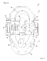
- FIG. 1 shows a first embodiment of an ultrasonic measuring device 10 according to the invention in different views. It is FIG. 1 a three-dimensional exterior view, FIG. 1b a longitudinal section, Figure 1c a cross-sectional view looking down on a base piece 12, Figure 1d a cross-sectional view upward on a measuring module 14 and Figure 1e a sectional view transverse to a main flow direction, ie the longitudinal axis of the base piece 12th
- the base piece 12 has flange portions 16 with which it is mounted in an existing pipeline, in which it replaces a corresponding pipe section. Alternatively, another attachment such as a thread may be provided. In the pipeline, a fluid flows in its axial direction, which is referred to as the main flow direction, for example, natural gas in a gas pipeline. With help a detachable connection 18, the measuring module 14 is mounted on the base piece 18. In an alternative embodiment, base piece 18 and measuring range 14 may also be formed in one piece.
- the ultrasonic measuring device 10 shifts the measurement of the pipeline in an axis transversely and in particular perpendicular to the main flow direction. For this purpose, the flow is conducted without abrupt changes in direction and without cross-sectional jumps in a loop, as in each case in the FIGS. 1a-e indicated by an arrow and explained in more detail below.
- the inflowing fluid is guided laterally upwards in the base piece 12 in a first deflection 20 from the main flow direction by 90 ° and exits the base piece 12 through a first opening 22. It flows through a first straight portion 24 and is then deflected in a 180 ° arc 26 in the opposite direction, in which it passes a second straight portion 28 which is arranged parallel to the first portion 24. Through a second opening 30 next to the first opening 22, the fluid re-enters the base piece 12, where it is again guided by a second deflection 32 laterally 90 ° back into the main flow device and thus leaves the ultrasonic measuring device 10 in the pipeline.
- a flow straightener 34 is arranged in the first straight portion 24 in the measuring module 14.
- the flow rectifier 34 is formed in a manner known per se and ensures that a uniform flow forms in the influx and enters the arc 26.
- the parallel thereto, strictly speaking antiparallel second straight portion 28 includes an ultrasonic measuring range 36, in which two pairs of associated ultrasonic transducer 38 each span an ultrasonic measuring path 40.
- a pair of ultrasonic transducers 38 with only one measuring path 40 is also sufficient, but for normalization reasons usually at least two measuring paths 40 are used. Additional measuring paths 40 are conceivable in order to further improve the measuring accuracy with remaining flow irregularities.
- An evaluation unit not shown, which is arranged for example as part of the measuring module 14 in the ultrasonic transducers 38 or in the outer wall of the measuring module 14, generates ultrasound and evaluates the received ultrasonic signals according to the method described in the introduction to determine the flow velocity of the fluid over a travel time difference ,
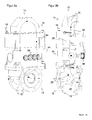
- FIG. 2 shows a further embodiment of the ultrasonic measuring device 10 according to the invention
- FIG. 2a a three-dimensional exterior view
- FIG. 2b a longitudinal section
- Figure 2c a sectional view across the main flow direction.
- like reference numerals designate the same or corresponding features.
- the measuring module 14 is the only attachment module.
- a bypass module 44 as a further attachment module, which can be mounted between the base piece 12 and the measuring module 14. Initially nothing changes at the flow guide and the loop through the bypass module 44, because the bypass module 44 comprises two extension pieces 46, 48 for the inflow and outflow.
- the bypass module 44 connects in a basic position via the connecting pieces 46, 48, the openings 22, 30 of the base piece 12 pressure-tight with the straight portions 24, 28 of the measuring module fourteenth
- the bypass module 44 is in FIG. 4a in a three-dimensional view and in FIG. 4b shown separately again in a longitudinal section.
- a trained as a T-shaped ball ball bypass deflection 50, 52 forms in a first position in a straight flow path, the connecting pieces 46, 48.
- the Bypassumlenkept 50, 52 Similar to the operation of a three-way ball valve transferred to a second position and then form a transverse line instead.
- FIG. 4b recognizable, wherein the bypass deflection 50 shown on the left would be rotated by 90 ° and the bypass deflection 52 shown on the right by 90 ° in the clockwise direction.
- a lever 54 and a mechanical coupling 56 of the two bypass deflectors 50, 52 is provided.
- This coupling is shown purely as an example in the figures as four gears to illustrate that the coupling 56 reverses the direction of rotation.
- the lever 54 In order to replace the measuring module 14, it is sufficient to actuate the lever 54 and thus to guide the flow of the fluid through the transverse line in the second position of the bypass deflections 50, 52.
- the measuring module 14 is thus depressurized and can be easily replaced, for example, against a pre-calibrated exchange measuring module.
- the lever 54 is again actuated to restore the first position of the bypass baffles 50, 52 and redirect the fluid across the loop through the ultrasonic measurement area 36.
- the fluid flow need not be interrupted at any moment of replacement.
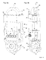
- FIG. 3 shows a further embodiment of the ultrasonic measuring device 10 according to the invention
- FIG. 3a a three-dimensional exterior view
- FIG. 3b a longitudinal section
- Figure 3c a sectional view across the main flow direction.
- FIG. 5a shows the calibration module 58 separately in a three-dimensional view and FIG. 5b a corresponding longitudinal section.
- the calibration module 58 has its own ultrasonic measuring range 60, in which a pair of ultrasonic transducers 62 span a measuring path 64. Again, additional ultrasonic transducers and thus additional measuring paths are possible.
- the calibration module is used to provide further flow velocity readings as a reference for the measuring module 14 to deliver. These measured values can be used for checking the plausibility of the measuring module 14 or for its calibration.
- the calibration module 58 is just one example of the advantageous use of additional attachment modules.
- additional measuring module between base piece 12 and bypass module 44, which delivers measured values, while the flow is guided through the transverse line of the bypass module 44 in the second position of the bypass deflections 50, 52.
- data on the flow rate can continue to be made available.
- different measuring modules for different pressure, different accuracy requirements, measuring ranges or composition of the fluid to be measured are provided.
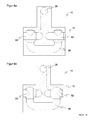
- FIG. 6 shows an alternative embodiment of a bypass line.
- the bypass line is not provided in a separate bypass module 44, but integrated into the base piece 12.
- FIG. 6a shows the situation during the measuring operation. The fluid flows through the base 12 into the metering module 14 and again through the base 12 back into the tubing. The bypass line 66 remains unused
- FIG. 6b represents the alternative situation during maintenance.
- the measuring module 14 is depressurized and can be replaced safely and without switching off the flow of the fluid. Meanwhile, the fluid flows through the bypass line 66.
- Bypass deflections 50, 52 are provided which switch over a three-way tap principle between the two operating modes of the bypass line 66.
Abstract
Description
Die Erfindung betrifft eine Ultraschallmessvorrichtung und ein Verfahren zur Messung der Strömungsgeschwindigkeit eines Fluids nach dem Oberbegriff von Anspruch 1 beziehungsweise 15.The invention relates to an ultrasonic measuring device and a method for measuring the flow velocity of a fluid according to the preamble of claims 1 and 15, respectively.
Fluidgeschwindigkeiten in Rohrleitungen und Kanälen können mittels Ultraschallmesstechnik nach dem Differenzlaufzeitverfahren ermittelt werden. Dabei werden UItraschallpulse von einem Paar Ultraschallwandler ausgesandt und empfangen, die einander gegenüber an einer Wandung der Rohrleitung an den Enden eines Messpfads quer zu der Strömung des Fluids angeordnet sind. Aus der Laufzeitdifferenz des Ultraschalls auf dem Messpfad mit der Strömung und in Gegenrichtung entgegen der Strömung wird die Strömungsgeschwindigkeit bestimmt. Die Ultraschallwandler arbeiten dabei wechselseitig als Sender und Empfänger. Die durch das Fluid transportierten Ultraschallsignale werden in Strömungsrichtung beschleunigt und gegen die Strömungsrichtung abgebremst. Die resultierende Laufzeitdifferenz wird mit geometrischen Größen zu einer mittleren Fluidgeschwindigkeit verrechnet. Mit der Querschnittsfläche ergibt sich daraus auch der Betriebsvolumenstrom, welcher bei nach Volumen abgerechnetem Fluid häufig die interessierende Messgröße ist.Fluid velocities in pipelines and channels can be determined by means of ultrasound measurement technology according to the differential transit time method. In this case, ultrasound pulses are emitted and received by a pair of ultrasonic transducers, which are arranged opposite each other on a wall of the pipeline at the ends of a measuring path transverse to the flow of the fluid. From the transit time difference of the ultrasound on the measuring path with the flow and in the opposite direction against the flow, the flow velocity is determined. The ultrasonic transducers work mutually as transmitter and receiver. The ultrasonic signals transported by the fluid are accelerated in the flow direction and braked against the flow direction. The resulting transit time difference is offset with geometric variables to a mean fluid velocity. With the cross-sectional area, this also results in the operating volume flow, which is often the measurement of interest in the case of volume-billed fluid.
Dieses bekannte Messprinzip ist in
- v: Strömungsgeschwindigkeit des Fluids in der Leitung
- L: Länge des Messpfades zwischen den beiden Ultraschallwandlern
- α: Winkel, unter dem die Ultraschallwandler senden und empfangen
- Q: Volumenstrom
- D: Durchmesser der Leitung
- tv: Laufzeit des Ultraschalls mit der Strömung
- tr: Laufzeit des Ultraschalls gegen die Strömung
- v: flow velocity of the fluid in the conduit
- L: length of the measuring path between the two ultrasonic transducers
- α: angle at which the ultrasonic transducers transmit and receive
- Q: flow rate
- D: diameter of the pipe
- t v : transit time of the ultrasound with the flow
- t r : transit time of the ultrasound against the flow
Daraus ergeben sich für die gesuchten Größen v und Q folgende Beziehungen: ![]()
![]()
![]()
![]()
Ein wichtiges und anspruchsvolles Anwendungsfeld sind Gaszähler für Erdgaspipelines, wo wegen der immensen beförderten Gasmengen und des Rohstoffwerts schon geringste Abweichungen in der Messgenauigkeit deutlich merklichen Werten entsprechen. Ultraschalldurchflussmesser werden in diesem Bereich der Großgasmengenmessung auf Grund ihrer Genauigkeit, Wartungsfreiheit und Selbstdiagnosemöglichkeiten bei Gastransport und Gaslagerung zunehmend eingesetzt. Im Bereich Verteilung/Distribution dagegen ist der Kostendruck gegenüber etablierten Technologien wie Turbinenradzählern und Drehkolbenzählern noch zu hoch.An important and demanding field of application are gas meters for natural gas pipelines, where even the slightest deviations in the measuring accuracy correspond to clearly noticeable values because of the immense transported gas quantities and the raw material value. Ultrasonic flowmeters are increasingly being used in this area of large-scale gas metering due to their accuracy, maintenance-free and self-diagnostic capabilities in gas transport and storage. In distribution / distribution, on the other hand, the cost pressure on established technologies such as turbine meters and rotary meters is still too high.
Um mit der erreichten Genauigkeit Anforderungen an eichpflichtige Messungen zu erfüllen, ist nämlich ein hoher Aufwand erforderlich. Da ein Ultraschallmesspfad die Strömungsgeschwindigkeit nur an definierten Positionen abtastet, wird letztlich die mittlere Strömungsgeschwindigkeit über den gesamten Strömungsquerschnitt extrapoliert. Hohe Genauigkeiten lassen sich daher nur erzielen, wenn die Strömung gut reproduzierbar ist, beziehungsweise ein ungestörtes Strömungsprofil aufweist oder wenn eine Vielzahl von Messpfaden die Unregelmäßigkeiten aufzulösen vermag. Um hohe Genauigkeiten zu erreichen, kann das Strömungsprofil gezielt beeinflusst werden, beispielsweise über Strömungsgleichrichter oder lange, gerade Einlaufstrecken. Strömungsgleichrichter sind aber nur begrenzt in der Lage, die Strömung zu vergleichmäßigen, und lange, gerade Einlaufstrecken benötigen viel Bauraum und stehen nicht immer zur Verfügung. Eine Messung auf zahlreichen Messpfaden erfordert ein entsprechend komplexes Messgerät.To meet with the achieved accuracy requirements for verifiable measurements, namely, a lot of effort is required. Since an ultrasonic measuring path scans the flow velocity only at defined positions, the average flow velocity is ultimately extrapolated over the entire flow cross section. High accuracies can therefore only be achieved if the flow is well reproducible, or has an undisturbed flow profile, or if a multiplicity of measuring paths is able to dissolve the irregularities. In order to achieve high accuracies, the flow profile can be specifically influenced, for example via flow straighteners or long, straight inlet sections. However, flow straighteners are limited in their ability to even out the flow, and long, straight inlet sections require a lot of space and are not always available. A measurement on numerous measuring paths requires a correspondingly complex measuring device.
Besonders beim Einsatz von Ultraschallmessgeräten im Bereich Distribution erfolgt die Installation typischerweise in Gasdruckregelstationen, in denen vom Mittel- oder Hochdruck der Transportleitung auf Nieder- beziehungsweise Mitteldruck des Verteilernetzes reduziert wird. Diese Reduktion erfolgt über Regelventile, und derartige Bauteile erzeugen Störschall im Ultraschallbereich, der sich den eigentlichen Messsignalen überlagert und somit die Messgenauigkeit beeinträchtigen kann.Especially when using ultrasound measuring devices in the field of distribution, the installation typically takes place in gas pressure regulating stations in which the medium or high pressure of the transport line is reduced to low or medium pressure of the distribution network. This reduction takes place via control valves, and such components generate noise in the ultrasonic range, which is superimposed on the actual measurement signals and thus can affect the measurement accuracy.
Insgesamt bedeutet dies für den Anwender herkömmlicher Ultraschallmessgeräte den Nachteil, dass zusätzliche Installationen vorgenommen werden müssen, welche erhöhte Kosten und Baugröße mit sich bringen.Overall, this means for the user of conventional ultrasonic measuring instruments the disadvantage that additional installations must be made, which entail increased costs and size.
Neben der Ultraschallmesstechnik werden mechanische Turbinenradzähler oder Drehkolbenzähler zur Gasmessung eingesetzt. Hier gibt es auch Ausführungen, bei denen die Strömung für den Zähler umgelenkt und nach der Messung wieder in die Strömungsrichtung der Rohrleitung zurückgelenkt wird. Für mechanische Messung ist die Ausbildung der Strömung weitgehend gleichgültig, so dass die Störung der ursprünglichen Strömung und Strömungsrichtung ohne Weiteres in Kauf genommen werden kann. Bei Ultraschallzählern ist man dagegen stets bestrebt, sie nur nach einer langen und vorzugsweise geraden Beruhigungsstrecke zu montieren, so dass die Strömung sich vergleichmäßigen kann, und dies durch Strömungsgleichrichter noch zu unterstützen. Weiterhin werden auch die Ultraschallzähler selbst so montiert und ausgebildet, dass das Fluid möglichst frei und ungestört strömen kann.In addition to ultrasonic measurement, mechanical turbine meters or rotary meters are used for gas measurement. There are also versions in which the flow is diverted for the counter and returned to the flow direction of the pipeline after the measurement. For mechanical measurement, the formation of the flow is largely indifferent, so that the disturbance of the original flow and flow direction can be readily accepted. In contrast, ultrasound counters always endeavor to mount them only after a long and preferably straight calming section, so that the flow can be uniformed, and this can still be supported by flow straighteners. Furthermore, the ultrasound counters themselves are mounted and designed so that the fluid can flow freely and undisturbed.
Die mechanische Messweise dieser Zähler hat außerdem den Nachteil, dass bewegte und damit stör- und verschleißanfällige Teile direkt in der Strömung angeordnet sind. Weiterhin fehlen die diagnostischen Eigenschaften, welche im Ultraschallzähler durch die Beobachtung zusätzlicher Messgrößen gewonnen werden können. Der Status des Messgeräts oder des Messprozesses kann also nicht überwacht und analysiert werden, beziehungsweise hierfür ist jeweils eine sehr kosten- und zeitaufwändige Prüfung erforderlich. Aufgrund der fehlenden Diagnosemöglichkeiten und damit fehlender Kontrolle über die Messgenauigkeit ist dies angesichts der hohen Werte, welche schon geringen Genauigkeitsabweichungen entsprechen können, für den Benutzer unbefriedigend.The mechanical measurement of this counter also has the disadvantage that moving and thus susceptible to wear and tear parts are located directly in the flow. Furthermore, the diagnostic properties that can be obtained in the ultrasonic counter by observing additional measured variables are missing. The status of the measuring device or the measuring process can therefore not be monitored and analyzed, and this is in each case a very costly and time-consuming test required. Due to the lack of diagnostic capabilities and thus lack of control over the measurement accuracy, this is unsatisfactory for the user in view of the high values, which may already correspond to low accuracy deviations.
Aus der
Die
Die
Die
In der
Die
In der
Ein weiterer Nachteil bei herkömmlichen Ultraschallmessgeräten ist die Art der Montage. Das Ultraschallmessgerät wird üblicherweise anstelle eines Rohrleitungsabschnitts angeflanscht. Entsprechend aufwändig ist ein Austausch oder eine Wartung. Derartige Wartungen sind auch erforderlich, um das eichpflichtige Ultraschallmessgerät regelmäßig zu überprüfen und zu rekalibrieren. Dabei ist die Kalibrierung in einem besonderen Hochdruckprüfstand vorzunehmen, der keineswegs in örtlicher Nähe zu dem Betriebsort liegen muss. Dabei muss der komplette Zähler einschließlich des drucktragenden Gehäuses aus der Leitung ausgebaut, eingeschickt und danach wieder eingebaut werden. Ein zwischenzeitlicher Betrieb ist nur möglich, wenn ein eigens für den Einsatzort kalibriertes Ersatzteil eingebaut wird.Another disadvantage with conventional ultrasonic measuring devices is the type of assembly. The ultrasonic measuring device is usually flange-mounted instead of a pipeline section. Correspondingly complex is an exchange or a maintenance. Such maintenance is also required to periodically review and recalibrate the custody transfer ultrasonic meter. The calibration must be carried out in a special high-pressure test facility, which by no means must be located in close proximity to the place of operation. The complete meter, including the pressure-bearing housing, must be removed from the line, sent in and then reinstalled. Interim operation is only possible if a spare part specially calibrated for the place of use is installed.
Durch den redundanten Leitungsaufbau entstehen erhebliche Mehrkosten. Der Mehraufwand ist besonders unökonomisch deshalb, weil die Ersatzleitung nur selten genutzt wird. Die typische Einsatzdauer der Ultraschallmessvorrichtung 200 beträgt fünf Jahre und mehr, während die Wartung oder ein Austausch der Ultraschallmessvorrichtung 200 mit einem rekalibrierten Ersatzteil nur wenige Stunden dauert.Due to the redundant cable structure, considerable additional costs arise. The extra effort is particularly uneconomical because the replacement line is rarely used. The typical service life of the
Nach der Wartung muss der Rohrleitungsabschnitt 202 wieder mit Druck beaufschlagt werden. Da in Erdgasversorgungsleitungen explosive, unter Druck stehende Medien transportiert werden, sind umfangreiche Sicherheitsmaßnahmen zu beachten, und es darf nur speziell geschultes Personal eingesetzt werden. Deshalb sind die Wartungsarbeiten herkömmlich mit hohen Kosten verbunden.After maintenance, the
Aus der
Auch die
Daher ist Aufgabe der Erfindung, eine genaue und einfache Ultraschallmessung von Strömungsgeschwindigkeiten zu ermöglichen.It is therefore an object of the invention to enable an accurate and simple ultrasonic measurement of flow velocities.
Diese Aufgabe wird durch eine Ultraschallmessvorrichtung gemäß Anspruch 1 und ein Verfahren zur Messung der Strömungsgeschwindigkeit eines Fluids gemäß Anspruch 15 gelöst. Dabei geht die erfindungsgemäße Lösung von dem Grundgedanken aus, das Fluid aus einer Hauptströmungsrichtung in der Rohrleitung in einen beispielsweise stutzenartigen Aufsatz abzulenken. Dabei wird die Strömung auf jedem Leitungsabschnitt nur um einen Höchstwinkel abgelenkt und in ihrem Querschnitt möglichst unverändert belassen. Dies wird durch eine Schleife erreicht, also anschaulich einen Looping oder jedenfalls einen Strömungsweg, der eine räumliche 360°-Kurve beschreibt. Auf diese Weise kann die Strömung unabhängig von den Leitungsabschnitten stromauf der Ultraschallmessvorrichtung und damit sehr reproduzierbar vermessen werden. Zum anderen wird der Ultraschallmessbereich wesentlich leichter zugänglich.This object is achieved by an ultrasonic measuring device according to claim 1 and a method for measuring the flow velocity of a fluid according to claim 15. In this case, the solution according to the invention is based on the basic idea of diverting the fluid from a main flow direction in the pipeline into a, for example, nozzle-like attachment. The flow is deflected on each line section only by a maximum angle and left as unchanged as possible in their cross section. This is achieved by a loop, viz., A loop, or at least a flow path that describes a 360 ° spatial curve. In this way, the flow can be independent of the pipe sections upstream of the ultrasonic measuring device and thus be measured very reproducible. On the other hand, the ultrasonic measuring range is much more accessible.
Die erfindungsgemäße Lösung hat den Vorteil, dass die Messstelle reproduzierbar von dem am Eingang des Messgerät vorliegenden Strömungsprofil akustisch entkoppelt ist und zugleich eine Schalldämmung gegenüber vorgeschalteten Störschallquellen erfolgt, beispielsweise gegenüber Druckregelventilen. Es entsteht nur ein geringer Druckverlust, so dass ausreichende Druckreserven für eine Strömungskonditionierung vorhanden sind. Die Ultraschallmessvorrichtung hat eine sehr kleine Einbaulänge und kommt wegen des reproduzierbaren Strömungsverhaltens mit einer minimalen Anzahl von Ultraschallmesspfaden aus.The solution according to the invention has the advantage that the measuring point is reproducibly acoustically decoupled from the flow profile present at the input of the measuring device and, at the same time, there is sound insulation with respect to upstream noise sources, for example against pressure regulating valves. There is only a slight pressure drop, so that sufficient pressure reserves for flow conditioning are available. The ultrasonic measuring device has a very small installation length and, because of the reproducible flow behavior, has a minimum number of ultrasonic measuring paths.
Dabei werden sämtliche Vorzüge der Ultraschallmessung gegenüber mechanischen Messprinzipien, wie Drehkolbenzähler oder Turbinenradzähler, mit allen einleitend genannten Vorteilen einschließlich stabiler Messwerte über einen größeren Durchflussbereich erzielt. Die erfindungsgemäße Strömungsführung ermöglicht einen modularen Aufbau der Ultraschallmessvorrichtung. Dabei kann ein drucktragender oder druckloser Ultraschallmessbereich beziehungsweise ein Ultraschallmessbereich für Hochdruck und Niederdruck gefertigt werden, mit freier konstruktiver Gestaltung hinsichtlich Materialauswahl, Wandstärke und Ausführung der Ultraschallwandler. Da der Ultraschallmessbereich gut zugänglich ist, kann die Dichtigkeit sowohl zur Umgebung als auch zwischen der Zuströmung und der Abströmung einfach nachgewiesen werden. Außerdem sind auch die Ultraschallwandler selbst gut zugänglich und somit einfach und kostengünstig kontaktierbar. Trotz dieser Vorteile hat die Ultraschallmessvorrichtung eine Konstruktion, die eine kostengünstige Herstellung erlaubt.All the advantages of ultrasonic measurement compared to mechanical measuring principles, such as rotary-piston meters or turbine wheel meters, are achieved with all of the aforementioned advantages including stable measured values over a larger flow range. The flow guide according to the invention allows a modular construction of the ultrasonic measuring device. In this case, a pressure-bearing or pressure-free ultrasonic measuring range or an ultrasonic measuring range for high pressure and low pressure can be manufactured, with free structural design with regard to material selection, wall thickness and design of the ultrasonic transducer. Since the ultrasonic measuring range is easily accessible, the tightness to the environment as well as between the inflow and the outflow can be easily detected. In addition, the ultrasonic transducers themselves are easily accessible and thus easy and inexpensive contactable. Despite these advantages, the ultrasonic measuring device has a construction which allows inexpensive production.
Die Schleife weist bevorzugt eine erste Ablenkung, einen Zuströmbereich, einen Bogen, einen Abströmbereich und eine zweite Ablenkung auf, so dass Fluid aus der Hauptströmungsrichtung durch die erste Ablenkung in den Zuströmbereich, von dort durch den Bogen in den Abströmbereich und schließlich durch die zweite Ablenkung zurück in die Hauptströmungsrichtung umlenkbar ist, wobei insbesondere die erste Ablenkung und die zweite Ablenkung einen rechten Winkel und der Bogen einen Winkel von 180° bilden. Alle diese Winkel müssen nicht notwendig ganz genau eingehalten werden, beispielsweise ist für die Ablenkungen auch ein Winkelbereich von 80°-100° oder sogar ein noch größerer Winkelbereich denkbar. Bei derartigen Abweichungen sollten jedoch abrupte Richtungswechsel und insgesamt eine zu unhandliche Bauform vermieden werden. Entsprechende Winkelabweichungen sind auch für den 180°-Bogen denkbar. Dabei müssen sich die Winkel insgesamt zu 360° addieren, damit das Fluid nach Durchströmen der Ultraschallmessvorrichtung erneut in der Hauptströmungsrichtung weiter strömt. Einen kleinen Beitrag zu diesem Gesamtwinkel können auch die Zuström- und Abströmbereiche durch Abweichungen von einer geradegestreckten Form leisten. Zu beachten ist, dass die Schleife eine dreidimensionale geometrische Form ist, so dass die Bedingung, wieder in der Ausgangsrichtung zu münden, längs und quer erfüllt werden muss.The loop preferably has a first deflection, inflow region, arc, outflow region and second deflection such that fluid from the main flow direction through the first deflection into the inflow region, thence through the arc into the outflow region and finally through the second deflection back in the main flow direction is deflectable, in particular, the first deflection and the second deflection form a right angle and the arc an angle of 180 °. All these angles need not necessarily be met exactly, for example, for the deflections, an angular range of 80 ° -100 ° or even an even wider range of angles is conceivable. In such deviations, however, should abrupt changes of direction and overall too bulky design be avoided. Corresponding angular deviations are also conceivable for the 180 ° bend. In this case, the total angle must add to 360 °, so that the fluid flows again after flowing through the ultrasonic measuring device in the main flow direction. A small contribution to this overall angle can also be made by the inflow and outflow areas by deviations from a straight stretched shape. It should be noted that the loop is a three-dimensional geometric shape, so that the condition, to open again in the exit direction, must be fulfilled longitudinally and transversely.
Zuströmbereich und Abströmbereich weisen bevorzugt jeweils einen nebeneinander angeordneten Teilbereich auf und sind parallel zueinander ausgerichtet, wobei insbesondere eine Ebene, welche die beiden geraden Teilbereiche umfasst, senkrecht zu der Hauptströmungsrichtung steht. Innerhalb des Zuströmbereichs und des Abströmbereichs sind damit keinerlei störende Strömungsumlenkungen. Durch die parallele Anordnung kann im Gegensatz beispielsweise zu einer konzentrischen Anordnung der Strömungsquerschnitt konstant gehalten werden. Indem die genannte Ebene in der genannten Weise angeordnet ist, entsteht eine Schleife praktisch sowohl in Längs- wie in Querrichtung zu der Rohrleitung. Damit lässt sich eine besonders gleichmäßige und symmetrische Strömungsführung und eine besonders kompakte Bauweise der Ultraschallmessvorrichtung erreichen.The inflow region and the outflow region preferably each have a subregion arranged next to one another and are aligned parallel to one another, wherein in particular a plane which comprises the two straight subregions is perpendicular to the main flow direction. Within the inflow region and the outflow region, there are therefore no disturbing flow diversions. Due to the parallel arrangement, in contrast to a concentric arrangement, for example, the flow cross section can be kept constant. By arranging said plane in said manner, a loop is formed practically in both the longitudinal and transverse directions of the pipeline. This makes it possible to achieve a particularly uniform and symmetrical flow guidance and a particularly compact design of the ultrasonic measuring device.
Die Schleife ist bevorzugt glatt und ohne scharfe Richtungsänderungen oder Einschnürungen ausgebildet, wobei insbesondere der Bogen eine Wandkontur aufweist, welche einen gezielten Strömungsabriss in einem für die Ultraschallmessung unkritischen Bereich bewirkt. Damit kann sich in dem Ultraschallmessbereich ein ausreichend beruhigtes Strömungsprofil ausbilden. Außerdem bleibt der Druckverlust minimal. Die spezielle Wandkontur in dem Bogen bewirkt einen gezielten Strömungsabriss in einem für die Ultraschallmessung unkritischen Bereich. In dem Ultraschallmessbereich wird dadurch eine Vergleichmäßigung des Strömungsprofils erreicht und störende Wirbel und Rückströmungsgebiete werden vermieden. So wird auch eine Messung bei hohen Strömungsgeschwindigkeiten und damit eine wesentliche Erweiterung des Messbereiches möglich.The loop is preferably formed smooth and without sharp changes in direction or constrictions, in particular, the arc has a wall contour, which causes a targeted stall in a non-critical for ultrasonic measurement area. This can form a sufficiently calmed flow profile in the ultrasonic measuring range. In addition, the pressure loss remains minimal. The special wall contour in the arc causes a targeted stall in a non-critical for ultrasonic measurement area. In the ultrasonic measuring range, a homogenization of the flow profile is thereby achieved and disturbing vortexes and return flow areas are avoided. Thus, a measurement at high flow velocities and thus a significant extension of the measuring range is possible.
In dem Zuströmbereich und/oder in dem Abströmbereich ist bevorzugt ein Strömungsgleichrichter vorgesehen. Dieser sorgt zusätzlich für eine reproduzierbare Strömung und damit hohe Messgenauigkeit. Besonders bei Anordnung im Zuströmbereich steht ausreichend Platz auch für komplexere Strömungsgleichrichter sowie durch den anschließenden Strömungsweg bis zu der Ultraschallmessstrecke auch ausreichend Wegstrecke für eine Vergleichmäßigung zur Verfügung. Wegen der erfindungsgemäßen Strömungsführung gibt es hinreichende Druckreserven für den Strömungsgleichrichter.In the inflow region and / or in the outflow region, a flow rectifier is preferably provided. This additionally ensures a reproducible flow and thus high measuring accuracy. Especially when arranged in the inflow area sufficient space is also available for more complex flow straighteners as well as through the subsequent flow path up to the ultrasonic measuring section also sufficient distance for a homogenization available. Because of the flow guide according to the invention, there are sufficient pressure reserves for the flow rectifier.
Der Ultraschallmessbereich ist bevorzugt in dem Abströmbereich vorgesehen, insbesondere mit genügend Abstand zu dem Bogen, so dass sich die Strömung bei Eintritt in den Ultraschallmessbereich reproduzierbar stabilisiert. Dabei sind noch bevorzugter gerade Teilstrecken des Abströmbereichs vor und/oder nach dem Ultraschallmessbereich angeordnet. Das Fluid hat dann zum Zeitpunkt der Ultraschallmessung schon einen Großteil der Schleife passiert und ist somit besonders effektiv von Störungen stromauf der Ultraschallmessvorrichtung entkoppelt. Dies gilt noch verstärkt, wenn sich in dem Zuströmbereich ein Strömungsgleichrichter befindet. Zusätzlich oder alternativ könnte aber auch in dem Abströmbereich ein Strömungsgleichrichter angeordnet werden.The ultrasound measuring range is preferably provided in the outflow region, in particular at a sufficient distance from the arc, so that the flow stabilizes reproducibly upon entry into the ultrasound measuring region. Even more preferably straight sections of the discharge area are arranged before and / or after the ultrasonic measuring area. The fluid has then passed a majority of the loop at the time of ultrasonic measurement and is therefore particularly effectively decoupled from disturbances upstream of the ultrasonic measuring device. This is even more pronounced if there is a flow rectifier in the inflow region. Additionally or alternatively, however, a flow rectifier could also be arranged in the outflow region.
Die Ultraschallwandler sind in dem Ultraschallmessbereich bevorzugt derart angeordnet, dass der ausgesandte und empfangene Ultraschall zumindest eine Komponente in Querrichtung der Strömung aufweist. So können die Ultraschallwandler seitlich montiert werden. Das Gegenstück zu einer solchen Ausführungsform mit Messung quer zu der Strömung sind Ultraschallwandler, die längs angeordnet werden, beispielsweise oben ausgangs des Bogens und unten am Strömungsausgang. Das ist deshalb ungünstiger, weil in die Messung nicht beruhigte Strömungsanteile eingehen, was zu ungenaueren und unzuverlässigeren Messwerten führt.The ultrasound transducers are preferably arranged in the ultrasound measuring range such that the ultrasound emitted and received has at least one component in the transverse direction of the flow. Thus, the ultrasonic transducers can be mounted laterally. The counterpart to such a transverse flow measurement embodiment are ultrasonic transducers which are longitudinally arranged, for example at the top of the arc and at the bottom of the flow outlet. This is unfavorable because the measurement is not calmed flow components, which leads to inaccurate and unreliable measured values.
Die Ultraschallmessvorrichtung weist bevorzugt ein rohrförmiges Basisstück mit Anschlussbereichen, insbesondere Flanschen für die Rohrleitung auf, welches die erste Ablenkung und die zweite Ablenkung umfasst. Dieses Basisstück ist kompatibel zu den Standardeinbaulängen beispielsweise von Turbinenradzählern oder Drehkolbengaszählern und wird in verschiedenen Nennweiten und mit verschiedenen Anschlussflanschen hergestellt, die für die jeweilige Rohrleitung benötigt werden. Das Basisstück verbleibt nach der Montage stets in der Rohrleitung und ist so als Grundgehäuse funktional und konstruktiv von der Messsektion trennbar. Damit kann ein einfach herzustellender und montagefreundlicher Messaufsatz gefertigt werden.The ultrasonic measuring device preferably has a tubular base piece with connecting areas, in particular flanges for the pipeline, which comprises the first deflection and the second deflection. This base is compatible with the standard installation lengths of, for example, turbine meters or rotary lobe meters and is manufactured in different sizes and with different connection flanges needed for the particular pipe. The base piece always remains in the pipeline after installation and can thus be functionally and constructively separated from the measuring section as a basic housing. This makes it possible to manufacture an easy-to-manufacture and easy-to-mount measuring attachment.
Die Ultraschallmessvorrichtung weist bevorzugt mindestens ein Aufsatzmodul auf, welches jeweils ein Verlängerungsstück für den Zuströmbereich und den Abströmbereich umfasst und welches mit dem Basisstück oder einem anderen Aufsatzmodul verbindbar und von dem Basisstück oder dem anderen Aufsatzmodul lösbar ist, wobei ein abschließendes Aufsatzmodul den Bogen umfasst. In der Ausführungsform mit der geringsten Anzahl von Aufsatzmodulen ist demnach nur das einzige abschließende Aufsatzmodul mit dem Bogen vorgesehen. In dem abschließenden Aufsatzmodul können die Verlängerungsstücke gegebenenfalls nur andeutungsweise und sehr kurz vorgesehen sein.The ultrasonic measuring device preferably has at least one attachment module, which in each case comprises an extension piece for the inflow region and the outflow region and which can be connected to the base piece or another attachment module and detached from the base piece or the other attachment module, a final attachment module comprising the sheet. Thus, in the embodiment with the least number of attachment modules, only the single final attachment module is provided with the signature. In the final attachment module, the extension pieces may optionally be provided only hinted and very short.
Durch die Aufsatzmodule können über dem Basisstück nach Bedarf zusätzliche Baugruppen montiert werden. Diese können beispielsweise eine Umleitung der Strömung, eine zusätzliche Konditionierung der Strömung oder zusätzliche Messaufgaben ermöglichen. Die äußeren Abmessungen der Ultraschallmessvorrichtung in der Rohrachse, also in Hauptströmungsrichtung, werden durch die Aufsatzmodule nicht verändert, denn die tatsächliche Einbaulänge wird allein durch die geometrischen Abmessungen des Basisstücks bestimmt. Die Ultraschallmessvorrichtung kann daher kompatibel zu bisher eingesetzten Gaszählern gebaut werden. Die Aufsatzmodule können einfach nach oben ausgetauscht werden, ohne dass das Basisstück aus der Rohrleitung genommen werden muss. Die Strömungsführung in der Ultraschallmessvorrichtung wird in erster Linie durch die Schleife innerhalb der Aufsatzmodule geprägt und ist damit weitgehend frei gestaltbar, ohne in die Rohrleitung eingreifen zu müssen. Die Modulbauweise aus Basisstück und Aufsatzmodulen erlaubt eine flexible und kostengünstige Fertigung, Montage, Veränderung und Wartung der Ultraschallmessvorrichtung.The add-on modules allow additional assemblies to be mounted above the base as needed. These can, for example, enable diversion of the flow, additional conditioning of the flow or additional measurement tasks. The outer dimensions of the ultrasonic measuring device in the tube axis, ie in the main flow direction, are not changed by the attachment modules, because the actual installation length is determined solely by the geometric dimensions of the base piece. The ultrasonic measuring device can therefore be built compatible with previously used gas meters. The attachment modules can simply be exchanged upwards without removing the base from the pipeline. The flow guidance in the ultrasound measuring device is primarily characterized by the loop within the attachment modules and can thus be largely freely designed without having to intervene in the pipeline. The modular design of base and top modules allows flexible and cost-effective production, assembly, modification and maintenance of the ultrasonic measuring device.
Die Ultraschallmessvorrichtung umfasst bevorzugt mindestens ein als Messmodul ausgebildetes Aufsatzmodul mit dem Ultraschallmessbereich und umfasst insbesondere auch den Strömungsgleichrichter. Das Messmodul kann außerhalb der Rohrleitung vorkalibriert werden. Bei einem Austausch der Ultraschallmessvorrichtung verbleibt dann das Basisstück in der Rohrleitung, und das vorhandene Messmodul wird gegen ein vorkalibriertes Messmodul ausgetauscht. Die Ausgestaltung des Ultraschallmessbereichs und der Strömungskonditionierung ist somit unabhängig von dem Basisstück und beliebig variierbar. Das Messmodul kann für jede Nennweite der Rohrleitung identisch aufgebaut sein, obwohl andererseits auch Anpassungen denkbar sind. Es können weitere oder alternative Messmodule vorgesehen sein, beispielsweise ein redundantes Messmodul für die Zeit des Austauschs, aber auch unterschiedliche Messmodule für andere Druckverhältnisse, andere Zusammensetzungen des Fluids und dergleichen.The ultrasound measuring device preferably comprises at least one attachment module designed as a measuring module with the ultrasound measuring region and, in particular, also comprises the flow rectifier. The measuring module can be pre-calibrated outside the pipeline. When replacing the ultrasonic measuring device then the base piece remains in the pipeline, and the existing measuring module is replaced with a pre-calibrated measuring module. The design of the ultrasonic measuring range and the flow conditioning is thus independent of the base piece and can be varied as desired. The measuring module can be constructed identically for each nominal diameter of the pipeline, although on the other hand also adjustments are conceivable. It is possible to provide further or alternative measuring modules, for example a redundant one Measuring module for the time of exchange, but also different measuring modules for other pressure conditions, other compositions of the fluid and the like.
Die Ultraschallmessvorrichtung weist bevorzugt ein als Bypassmodul ausgebildetes Aufsatzmodul mit einer Querleitung zwischen dem Zuströmbereich und dem Abströmbereich oder eine in das Basisstück integrierte Querleitung auf, wobei eine Bypassumlenkung vorgesehen ist, die wahlweise in einer Stellung die Strömung zu der Querleitung und aus der Querleitung sperrt und die Strömung zu dem Zuströmbereich und aus dem Abströmbereich freigibt und in einer anderen Stellung die Strömung zu dem Zuströmbereich und aus dem Abströmbereich sperrt und die Strömung zu der Querleitung und aus der Querleitung freigibt. Mit Hilfe der Querleitung kann der Volumenstrom so umgeleitet werden, dass ein anderes Aufsatzmodul wie beispielsweise ein Messmodul drucklos montierbar und demontierbar ist. Der Fluidstrom, beispielsweise der Gasstrom zum Verbraucher, wird dabei nicht unterbrochen. Damit entfallen zusätzliche bauliche Maßnahmen an der Rohrleitung, wie Absperreinrichtungen, Bypassleitungen, Entlüftungseinrichtungen oder dergleichen, und dies führt zu einer erheblichen Reduktion der Anlagenkosten. Die Rohrleitung selbst bleibt während der Wartungsarbeiten mit dem Betriebsdruck beaufschlagt. Da kein Entlüften und Befüllen des zu wartenden Rohrleitungsabschnittes erforderlich ist, verkürzen sich die Wartungszeiten. Außerdem sind wegen des Verbleibens des Basisstücks in der Rohrleitung keine aufwändigen Dichtheitstests bei Wiederinbetriebnahme der Rohrstrecke notwendig. Die Bypassleitung kann dabei in das Basisstück integriert sein. Alternativ ist ein eigenes Bypassmodul vorgesehen.The ultrasonic measuring device preferably has a bypass module designed as a bypass module with a transverse line between the inflow region and the outflow region or integrated into the base section transverse line, wherein a bypass deflection is provided which selectively blocks in one position, the flow to the transverse line and from the transverse line and the Flow to the inflow and outflow area releases and locks in another position, the flow to the inflow and outflow area and releases the flow to the transverse line and from the transverse line. With the help of the transverse line, the volume flow can be redirected so that another attachment module such as a measuring module can be mounted without pressure and disassembled. The fluid flow, for example, the gas flow to the consumer, is not interrupted. This eliminates additional structural measures on the pipeline, such as shut-off devices, bypass lines, venting devices or the like, and this leads to a considerable reduction of the system costs. The pipeline itself is subjected to the operating pressure during maintenance work. Since no venting and filling of the pipe section to be serviced is required, the maintenance times are shortened. In addition, because of the whereabouts of the base piece in the pipeline, no elaborate leak tests are required when the pipe section is restarted. The bypass line can be integrated into the base piece. Alternatively, a separate bypass module is provided.
Das Bypassmodul ist so ausgeführt, dass im Messbetrieb die Strömung zu den übrigen Modulen und insbesondere dem Messmodul wenig beeinflusst wird. Dadurch sind keine zusätzlichen Maßnahmen in diesen Modulen notwendig, um deren einwandfreie Funktion und eine ungestörte Messung zu gewährleisten. Durch den modularen Aufbau passt das Bypassmodul an die anderen Aufsatzmodule oder das Basisstück. Auch ist eine nachträgliche Montage des Bypassmoduls in bereits eingebaute Ultraschallmessvorrichtungen möglich.The bypass module is designed so that the flow to the other modules and in particular the measuring module is little influenced during measurement operation. As a result, no additional measures in these modules are necessary to ensure their proper functioning and undisturbed measurement. Due to the modular design, the bypass module fits to the other add-on modules or the base piece. Also, a subsequent installation of the bypass module in already installed ultrasonic measuring devices is possible.
Die Bypassumlenkung ist bevorzugt nach dem Prinzip eines Dreiwegehahns ausgebildet und weist insbesondere zwei T-fömig gelochte Kugeln mit Dichtungen auf, welche untereinander gekoppelt und somit gemeinsam aus der einen Stellung in die andere Stellung überführbar sind. Das wahlweise Umleiten der Strömung in die Querleitung, beispielsweise zum Austausch eines darüber angeordneten Aufsatzmoduls, oder zurück in die gesamte Schleife der Ultraschallmessvorrichtung ist so sehr einfach und zuverlässig möglich, beispielsweise über einen Hebel an der Außenseite. Das einfache Betätigen der kugelhahnartigen Konstruktion erfordert keinerlei tiefere Kenntnisse, und deshalb ist ein Austausch von Aufsatzmodulen auch mit weniger sicherheitstechnisch geschultem Personal möglich. Alternativ zu einer Bypassumlenkung nach dem Prinzip des Dreiwegehahns sind andere Formen von Ventilen, Schiebern, Klappen und dergleichen denkbar.The bypass deflection is preferably designed according to the principle of a three-way cock and in particular has two T-shaped perforated balls with seals, which are coupled together and thus jointly from one position to the other position can be transferred. The optional diverting the flow into the transverse line, for example, to replace an attached top module, or back into the entire loop of the ultrasonic measuring device is so very easy and reliable possible, for example via a lever on the outside. The simple operation of the ball valve-like construction requires no deeper knowledge, and therefore an exchange of attachment modules is possible even with less safety-trained personnel. As an alternative to a bypass diversion according to the principle of the three-way cock, other forms of valves, slides, flaps and the like are conceivable.
Die Ultraschallmessvorrichtung weist bevorzugt ein als Kalibrierungsmodul ausgebildetes Aufsatzmodul mit mindestens einem Paar Ultraschallwandler zur Plausibilisierung oder Kalibrierung der Messwerte des Ultraschallmessbereichs auf. Das Kalibrierungsmodul dient somit als Referenzmodul für ein Messmodul.The ultrasonic measuring device preferably has an attachment module designed as a calibration module with at least one pair of ultrasonic transducers for plausibility checking or calibration of the measured values of the ultrasound measuring range. The calibration module thus serves as a reference module for a measurement module.
Bevorzugt ist die Verwendung der erfindungsgemäßen Ultraschallmessvorrichtung als Gaszähler an einer Gaspipeline. Dabei kommen die genannten Vorteile besonders gut zum Tragen, um eine zuverlässige, vom Betriebsort weitgehend unabhängige und der Eichpflicht genügende Messung sicherzustellen.The use of the ultrasonic measuring device according to the invention as a gas meter on a gas pipeline is preferred. The advantages mentioned are particularly well-suited to ensure a reliable, largely independent of the location and the calibration requirement sufficient measurement.
Das erfindungsgemäße Verfahren kann auf ähnliche Weise weitergebildet werden und zeigt dabei ähnliche Vorteile. Derartige vorteilhafte Merkmale sind beispielhaft, aber nicht abschließend in den sich an die unabhängigen Ansprüche anschließenden Unteransprüchen beschrieben.The method according to the invention can be developed in a similar manner and shows similar advantages. Such advantageous features are described by way of example but not exhaustively in the subclaims following the independent claims.
Die Erfindung wird nachstehend auch hinsichtlich weiterer Merkmale und Vorteile beispielhaft anhand von Ausführungsformen und unter Bezug auf die beigefügte Zeichnung näher erläutert. Die Abbildungen der Zeichnung zeigen in:
- Fig. 1a
- eine dreidimensionale Außenansicht einer ersten Ausführungsform einer erfindungsgemäßen Ultraschallmessvorrichtung;
- Fig. 1 b
- ein Längsschnitt der Ultraschallmessvorrichtung gemäß
Figur 1 a; - Fig. 1c
- ein Querschnitt der Ultraschallmessvorrichtung gemäß
Fig. 1a in Sichtrichtung auf ein Basisstück; - Fig. 1 d
- ein Querschnitt analog
Figur 1d mit der entgegengesetzten Blickrichtung auf eine Messsektion; - Fig. 1 e
- eine Schnittdarstellung der Ultraschallmessvorrichtung gemäß
Fig. 1 a quer zu einer Hauptströmungsrichtung des Fluids;
- Fig. 2a
- eine dreidimensionale Außenansicht einer zweiten Ausführungsform einer erfindungsgemäßen Ultraschallmessvorrichtung mit einem Bypass;
- Fig. 2b
- ein Längsschnitt der Ultraschallmessvorrichtung gemäß
Figur 2a ; - Fig. 2c
- eine Schnittdarstellung der Ultraschallmessvorrichtung gemäß
Figur 2a quer zu einer Hauptströmungsrichtung des Fluids; - Fig. 3a
- eine dreidimensionale Außenansicht einer zweiten Ausführungsform einer erfindungsgemäßen Ultraschallmessvorrichtung mit einem Bypass und einer Referenzmesssektion;
- Fig. 3b
- ein Längsschnitt der Ultraschallmessvorrichtung gemäß
Figur 3a ; - Fig. 3c
- eine Schnittdarstellung der Ultraschallmessvorrichtung gemäß
Figur 3a quer zu einer Hauptströmungsrichtung des Fluids; - Fig. 4a
- eine dreidimensionale Außenansicht eines Bypassmoduls;
- Fig. 4b
- ein Längsschnitt durch das Bypassmodul gemäß
Figur 4a ; - Fig. 5a
- eine dreidimensionale Außenansicht eines Kalibrierungsmoduls;
- Fig. 5b
- ein Längsschnitt durch das Bypassmodul gemäß
Figur 5a ; - Fig. 6a
- eine Schnittdarstellung eines Basisstücks mit integrierter Bypassleitung, wobei die Bypassleitung geschlossen ist und das Fluid durch die Messsektion strömt;
- Fig. 6b
- eine Schnittdarstellung gemäß
Fig. 6a bei offener Bypassleitung und druckloser Messsektion; - Fig. 7
- eine herkömmliche Anordnung zweier Ultraschallwandler quer zu einer Strömungsrichtung eines Fluids zur Erläuterung des Messprinzips; und
- Fig. 8
- eine herkömmliche Rohrleitungsanordnung mit einer redundanten Rohrführung zur Umleitung des Fluids während eines Austauschs einer Ultraschallmessvorrichtung.
- Fig. 1a
- a three-dimensional exterior view of a first embodiment of an ultrasonic measuring device according to the invention;
- Fig. 1 b
- a longitudinal section of the ultrasonic measuring device according to
FIG. 1 a; - Fig. 1c
- a cross section of the ultrasonic measuring device according to
Fig. 1a in sight on a base piece; - Fig. 1 d
- a cross section analog
Figure 1d with the opposite viewing direction on a measuring section; - Fig. 1 e
- a sectional view of the ultrasonic measuring device according to
Fig. 1 a transverse to a main flow direction of the fluid;
- Fig. 2a
- a three-dimensional external view of a second embodiment of an ultrasonic measuring device according to the invention with a bypass;
- Fig. 2b
- a longitudinal section of the ultrasonic measuring device according to
FIG. 2a ; - Fig. 2c
- a sectional view of the ultrasonic measuring device according to
FIG. 2a transverse to a main flow direction of the fluid; - Fig. 3a
- a three-dimensional exterior view of a second embodiment of an ultrasonic measuring device according to the invention with a bypass and a reference measuring section;
- Fig. 3b
- a longitudinal section of the ultrasonic measuring device according to
FIG. 3a ; - Fig. 3c
- a sectional view of the ultrasonic measuring device according to
FIG. 3a transverse to a main flow direction of the fluid; - Fig. 4a
- a three-dimensional exterior view of a bypass module;
- Fig. 4b
- a longitudinal section through the bypass module according to
FIG. 4a ; - Fig. 5a
- a three-dimensional exterior view of a calibration module;
- Fig. 5b
- a longitudinal section through the bypass module according to
FIG. 5a ; - Fig. 6a
- a sectional view of a base piece with integrated bypass line, wherein the bypass line is closed and the fluid flows through the measuring section;
- Fig. 6b
- a sectional view according to
Fig. 6a with open bypass line and pressure-free measuring section; - Fig. 7
- a conventional arrangement of two ultrasonic transducers transverse to a flow direction of a fluid to explain the measuring principle; and
- Fig. 8
- a conventional piping arrangement with a redundant piping for the diversion of the fluid during an exchange of an ultrasonic measuring device.
Das Basisstück 12 weist Flanschbereiche 16 auf, mit denen es in eine bestehende Rohrleitung montiert wird, in der es einen entsprechenden Rohrleitungsabschnitt ersetzt. Alternativ kann auch eine andere Befestigung wie etwa ein Gewinde vorgesehen sein. In der Rohrleitung strömt ein Fluid in dessen axialer Richtung, die als Hauptströmungsrichtung bezeichnet wird, beispielsweise Erdgas in einer Gaspipeline. Mit Hilfe einer lösbaren Verbindung 18 ist das Messmodul 14 auf dem Basisstück 18 montiert. In einer alternativen Ausführungsform können Basisstück 18 und Messbereich 14 auch einstückig ausgebildet sein.The
Die Ultraschallmessvorrichtung 10 verlagert die Messung von der Rohrleitung in eine Achse quer und insbesondere senkrecht zu der Hauptströmungsrichtung. Dazu wird die Strömung ohne abrupte Richtungsänderungen und ohne Querschnittssprünge in einer Schleife geführt, wie jeweils in den
Das einströmende Fluid wird in dem Basisstück 12 in einer ersten Ablenkung 20 aus der Hauptströmungsrichtung um 90° seitlich nach oben geführt und tritt durch eine erste Öffnung 22 aus dem Basisstück 12 aus. Es durchströmt einen ersten geraden Teilbereich 24 und wird anschließend in einem 180°-Bogen 26 in die Gegenrichtung umgelenkt, in der es einen zweiten geraden Teilbereich 28 passiert, der parallel zu dem ersten Teilbereich 24 angeordnet ist. Durch eine zweite Öffnung 30 neben der ersten Öffnung 22 tritt das Fluid wieder in das Basisstück 12 ein, wo es durch eine zweite Ablenkung 32 erneut um 90° seitlich nach unten zurück in die Hauptströmungseinrichtung geführt wird und so die Ultraschallmessvorrichtung 10 in die Rohrleitung verlässt.The inflowing fluid is guided laterally upwards in the
In dem ersten geraden Teilbereich 24 in dem Messmodul 14 ist ein Strömungsgleichrichter 34 angeordnet. Der Strömungsgleichrichter 34 ist in einer an sich bekannten Weise ausgebildet und sorgt dafür, dass sich im Zustrom eine vergleichmäßigte Strömung bildet und in den Bogen 26 eintritt. Der hierzu parallele, genaugenommen antiparallele zweite gerade Teilbereich 28 enthält einen Ultraschallmessbereich 36, in dem zwei Paare einander zugehöriger Ultraschallwandler 38 jeweils einen Ultraschallmesspfad 40 aufspannen. Grundsätzlich genügt auch ein Paar Ultraschallwandler 38 mit nur einem Messpfad 40, aber aus Normierungsgründen werden gewöhnlich mindestens zwei Messpfade 40 verwendet. Es sind zusätzliche Messpfade 40 denkbar, um die Messgenauigkeit bei verbleibenden Unregelmäßigkeiten der Strömung weiter zu verbessern. Eine nicht dargestellte Auswertungseinheit, welche beispielsweise als Teil des Messmoduls 14 bei den Ultraschallwandlern 38 oder in der Außenwandung des Messmoduls 14 angeordnet ist, erzeugt Ultraschall und wertet die empfangenen Ultraschallsignale nach dem einleitend beschriebenen Verfahren aus, um über eine Laufzeitdifferenz die Strömungsgeschwindigkeit des Fluids zu ermitteln.In the first
In allen Strömungsbereichen werden scharfe Richtungsänderungen und Strömungseinschnürungen vermieden. Das gilt auch für den Bereich des Bogens 26, in dem die Strömung hinter dem Strömungsgleichrichter 34 dem Ultraschallmessbereich 36 zugeführt wird. Allerdings ist es vorteilhaft, die Innenwandung des Bogens 26 mit der dargestellten besonderen Wandkontur 42 zu versehen. Die Wandkontur 42 weist zunächst einen flachen Teilbereich auf, ehe sie in einen Bogen übergeht, und bildet so einen kleinen Vorsprung. Dies erzeugt einen gezielten Strömungsabriss in einem für die Ultraschallmessung unkritischen Bereich. Damit wird ein unerwünschter Strömungsabriss innerhalb des oder nahe dem Ultraschallmessbereich 38 verhindert und die Messung somit weiter stabilisiert.In all flow areas, sharp changes in direction and flow constrictions are avoided. This also applies to the region of the
In der Ausführungsform gemäß
Das Bypassmodul 44 ist in
Zur vereinfachten synchronen Betätigung der Bypassumlenkungen 50, 52 ist ein Hebel 54 und eine mechanische Kopplung 56 der beiden Bypassumlenkungen 50, 52 vorgesehen. Diese Kopplung ist in den Figuren rein beispielhaft als vier Zahnräder dargestellt, um zu illustrieren, dass die Kopplung 56 die Drehrichtung umkehrt.For simplified synchronous actuation of the
Um nun das Messmodul 14 auszutauschen, genügt es, den Hebel 54 zu betätigen und damit in der zweiten Stellung der Bypassumlenkungen 50, 52 die Strömung des Fluids durch die Querleitung zu führen. Das Messmodul 14 wird dadurch drucklos und kann problemlos ausgetauscht werden, beispielsweise gegen ein vorkalibriertes Austauschmessmodul. Nach erfolgtem Austausch wird der Hebel 54 erneut betätigt, damit die erste Stellung der Bypassumlenkungen 50, 52 wiederhergestellt und das Fluid erneut über die Schleife durch den Ultraschallmessbereich 36 geführt. Der Fluidstrom muss zu keinem Augenblick des Austauschs unterbrochen werden.In order to replace the measuring
Im Unterschied zu der Ausführungsform gemäß
Das Kalibrierungsmodul 58 weist einen eigenen Ultraschallmessbereich 60 auf, in dem ein Paar Ultraschallwandler 62 einen Messpfad 64 aufspannen. Auch hier sind zusätzliche Ultraschallwandler und damit zusätzliche Messpfade möglich. Das Kalibrierungsmodul dient dazu, weitere Messwerte für die Strömungsgeschwindigkeit als Referenz für das Messmodul 14 zu liefern. Diese Messwerte können zur Plausibilisierung des Messmoduls 14 oder zu dessen Kalibrierung verwendet werden.The
Das Kalibrierungsmodul 58 ist nur ein Beispiel des vorteilhaften Einsatzes weiterer Aufsatzmodule. Beispielsweise ist in einer weiteren Ausführungsform denkbar, ein zusätzliches Messmodul zwischen Basisstück 12 und Bypassmodul 44 zu montieren, welches Messwerte liefert, während die Strömung durch die Querleitung des Bypassmoduls 44 in der zweiten Stellung der Bypassumlenkungen 50, 52 geführt wird. Damit können während des Austauschs oder der Wartung des Messmoduls 14 weiterhin Daten über die Strömungsgeschwindigkeit zur Verfügung gestellt werden. In einer weiteren alternativen Ausführungsform werden verschiedene Messmodule für unterschiedlichen Druck, unterschiedliche Genauigkeitsanforderungen, Messbereiche oder Zusammensetzung des zu messenden Fluids bereitgestellt.The
Claims (15)
dass die Umlenkeinheit (20, 26, 32) eine Schleife bildet.An ultrasonic measuring device (10) for measuring the flow rate of a fluid flowing in a pipeline in a main flow direction, the ultrasonic measuring device (10) having an ultrasonic measuring section (36) with at least one pair of ultrasonic transducers (38), an evaluation unit for determining the flow velocity from a transit time difference of with and against the flow of emitted and received ultrasound and a deflection unit, by means of which the fluid from the main flow direction is deflectable and the ultrasonic measuring range (36) can be supplied, characterized
that the deflection unit (20, 26, 32) forms a loop.
wobei die Schleife eine erste Ablenkung (20), einen Zuströmbereich, einen Bogen (26), einen Abströmbereich und eine zweite Ablenkung (32) aufweist, so dass Fluid aus der Hauptströmungsrichtung durch die erste Ablenkung (20) in den Zuströmbereich (24), von dort durch den Bogen (26) in den Abströmbereich (28) und schließlich durch die zweite Ablenkung (32) zurück in die Hauptströmungsrichtung umlenkbar ist, wobei insbesondere die erste Ablenkung (20) und die zweite Ablenkung (32) einen rechten Winkel und der Bogen (26) einen Winkel von 180° bilden.Ultrasonic measuring device (10) according to claim 1,
wherein the loop has a first deflection (20), an inflow region, an arc (26), a discharge region and a second deflection (32), so that fluid from the main flow direction through the first deflection (20) in the inflow region (24), from there through the arc (26) in the outflow region (28) and finally by the second deflection (32) is deflected back into the main flow direction, in particular the first deflection (20) and the second deflection (32) a right angle and the Arc (26) form an angle of 180 °.
wobei Zuströmbereich und Abströmbereich jeweils einen nebeneinander angeordneten Teilbereich (24, 28) aufweisen und parallel zueinander ausgerichtet sind, wobei insbesondere eine Ebene, welche die beiden geraden Teilbereiche (24, 28) umfasst, senkrecht zu der Hauptströmungsrichtung steht.Ultrasonic measuring device (10) according to claim 2,
wherein inflow region and outflow region each have a juxtaposed partial region (24, 28) and are aligned parallel to one another, wherein in particular a plane which comprises the two straight partial regions (24, 28) is perpendicular to the main flow direction.
wobei die Schleife glatt und ohne scharfe Richtungsänderungen oder Einschnürungen ausgebildet ist, wobei insbesondere der Bogen (26) eine Wandkontur (42) aufweist, welche einen gezielten Strömungsabriss in einem für die Ultraschallmessung unkritischen Bereich bewirkt.Ultrasonic measuring device (10) according to claim 2 or 3,
wherein the loop is formed smoothly and without sharp changes in direction or constrictions, wherein in particular the arc (26) has a wall contour (42), which causes a targeted stall in a non-critical for ultrasonic measurement range.
die ein rohrförmiges Basisstück (12) mit Anschlussbereichen (16), insbesondere Flanschen für die Rohrleitung aufweist, welches die erste Ablenkung (20) und die zweite Ablenkung (32) umfasst.Ultrasonic measuring device (10) according to one of claims 2 to 7,
which comprises a tubular base piece (12) with connection areas (16), in particular flanges for the pipeline, which comprises the first deflection (20) and the second deflection (32).
die mindestens ein Aufsatzmodul (14, 44 58) aufweist, welches jeweils ein Verlängerungsstück für den Zuströmbereich und den Abströmbereich umfasst und welches mit dem Basisstück (12) oder einem anderen Aufsatzmodul (14, 44, 58) verbindbar und von dem Basisstück (12) oder dem anderen Aufsatzmodul (14, 44, 58) lösbar ist, wobei ein abschließendes Aufsatzmodul (14, 44, 58) den Bogen (26) umfasst.Ultrasonic measuring device (10) according to one of claims 2 to 8,
the at least one attachment module (14, 44 58), which in each case comprises an extension piece for the inflow region and the outflow region and which can be connected to the base piece (12) or another attachment module (14, 44, 58) and separated from the base piece (12). or the other attachment module (14, 44, 58) is detachable, wherein a final attachment module (14, 44, 58) comprises the sheet (26).
die mindestens ein als Messmodul (14) ausgebildetes Aufsatzmodul mit dem Ultraschallmessbereich (36) umfasst.Ultrasonic measuring device (10) according to claim 9,
which comprises at least one attachment module designed as a measurement module (14) with the ultrasonic measurement region (36).
die ein als Bypassmodul (44) ausgebildetes Aufsatzmodul mit einer Querleitung zwischen dem Zuströmbereich und dem Abströmbereich oder eine in das Basisstück (12) integrierte Querleitung aufweist, wobei eine Bypassumlenkung (50, 52) vorgesehen ist, die wahlweise in einer Stellung die Strömung zu der Querleitung und aus der Querleitung sperrt und die Strömung zu dem Zuströmbereich und aus dem Abströmbereich freigibt und in einer anderen Stellung die Strömung zu dem Zuströmbereich und aus dem Abströmbereich sperrt und die Strömung zu der Querleitung und aus der Querleitung freigibt.Ultrasonic measuring device (10) according to claim 9 or 10,
which has an attachment module designed as a bypass module (44) with a transverse line between the inflow region and the outflow region or a transverse line integrated into the base piece (12), wherein a bypass diversion (50, 52) is provided, which selectively blocks in one position the flow to the transverse line and from the transverse line and the flow to the inflow and outflow area releases and locks in another position, the flow to the inflow and outflow area and releases the flow to the cross line and from the cross line.
wobei die Bypassumlenkung (50, 52) nach dem Prinzip eines Dreiwegehahns ausgebildet ist, insbesondere zwei T-fömig gelochte Kugeln mit Dichtungen aufweist, welche untereinander gekoppelt und somit gemeinsam aus der einen Stellung in die andere Stellung überführbar sind.Ultrasonic measuring device (10) according to claim 11,
wherein the bypass deflection (50, 52) is designed according to the principle of a three-way cock, in particular two T-shaped perforated balls having seals which are coupled together and thus jointly from one position to the other position can be transferred.
die ein als Kalibrierungsmodul (58) ausgebildetes Aufsatzmodul mit mindestens einem Paar Ultraschallwandler (62) zur Plausibilisierung oder Kalibrierung der Messwerte des Ultraschallmessbereichs (36) aufweist.Ultrasonic measuring device (10) according to one of claims 10 to 12,
comprising an attachment module designed as a calibration module (58) with at least one pair of ultrasonic transducers (62) for plausibility checking or calibration of the measured values of the ultrasound measuring range (36).
dadurch gekennzeichnet,
dass die Ultraschallmessung stattfindet, während das Fluid derart umgelenkt wird, dass es in einer Schleife strömt.A method of measuring the flow rate of a fluid flowing in a conduit in a main flow direction, the flow velocity being determined from a transit time difference of ultrasound emitted and received by and against the flow of a pair of ultrasonic transducers (38) in an ultrasound sensing region (36) the fluid is deflected for measurement from the main flow direction and the ultrasonic measuring range (36),
characterized,
that the ultrasonic measurement takes place while the fluid is deflected so that it flows in a loop.
Priority Applications (5)
| Application Number | Priority Date | Filing Date | Title |
|---|---|---|---|
| PL10156936T PL2375224T3 (en) | 2010-03-18 | 2010-03-18 | Ultrasound measuring device and method for monitoring the flow speed of a liquid |
| EP10156936.6A EP2375224B1 (en) | 2010-03-18 | 2010-03-18 | Ultrasound measuring device and method for monitoring the flow speed of a liquid |
| US13/049,323 US8776613B2 (en) | 2010-03-18 | 2011-03-16 | Ultrasonic measurement apparatus having a deflection unit forming a loop |
| RU2011109911/28A RU2545358C2 (en) | 2010-03-18 | 2011-03-17 | Ultrasonic measuring device and fluid medium flow rate measuring method |
| CN201110070393XA CN102192767B (en) | 2010-03-18 | 2011-03-18 | Ultrasound measuring device and method for monitoring the flow speed of a liquid |
Applications Claiming Priority (1)
| Application Number | Priority Date | Filing Date | Title |
|---|---|---|---|
| EP10156936.6A EP2375224B1 (en) | 2010-03-18 | 2010-03-18 | Ultrasound measuring device and method for monitoring the flow speed of a liquid |
Publications (2)
| Publication Number | Publication Date |
|---|---|
| EP2375224A1 true EP2375224A1 (en) | 2011-10-12 |
| EP2375224B1 EP2375224B1 (en) | 2016-02-10 |
Family
ID=42753355
Family Applications (1)
| Application Number | Title | Priority Date | Filing Date |
|---|---|---|---|
| EP10156936.6A Active EP2375224B1 (en) | 2010-03-18 | 2010-03-18 | Ultrasound measuring device and method for monitoring the flow speed of a liquid |
Country Status (5)
| Country | Link |
|---|---|
| US (1) | US8776613B2 (en) |
| EP (1) | EP2375224B1 (en) |
| CN (1) | CN102192767B (en) |
| PL (1) | PL2375224T3 (en) |
| RU (1) | RU2545358C2 (en) |
Cited By (3)
| Publication number | Priority date | Publication date | Assignee | Title |
|---|---|---|---|---|
| EP3006903A1 (en) | 2014-10-10 | 2016-04-13 | SICK Engineering GmbH | Flow measuring device for measuring a parameter of a fluid flow |
| EP3296704A1 (en) | 2016-09-16 | 2018-03-21 | Energoflow AG | Flowmeter |
| DE102016117478A1 (en) | 2016-09-16 | 2018-03-22 | Energoflow Ag | fluid meter |
Families Citing this family (12)
| Publication number | Priority date | Publication date | Assignee | Title |
|---|---|---|---|---|
| US9711709B2 (en) * | 2013-08-08 | 2017-07-18 | General Electric Company | Transducer systems |
| RU2544256C1 (en) * | 2013-11-15 | 2015-03-20 | Александр Михайлович Деревягин | Device to measure speed of fluid medium flow |
| CN104280083A (en) * | 2014-10-20 | 2015-01-14 | 合肥科迈捷智能传感技术有限公司 | Hollow square-shaped ultrasonic flowmeter without straight pipe mounting requirement |
| US20170082469A1 (en) * | 2015-09-21 | 2017-03-23 | Honeywell International Inc. | Inline ultrasonic meter (usm) condition based monitoring (cbm)-based adaptation to maintain high accuracy under various flow conditions |
| CN106525177A (en) * | 2016-12-15 | 2017-03-22 | 王成刚 | Fluid pipeline with specific rectifying form |
| CN206440316U (en) * | 2017-01-23 | 2017-08-25 | 青岛海威茨仪表有限公司 | A kind of channel ultrasonic low |
| CN110691960A (en) * | 2017-05-22 | 2020-01-14 | 松下知识产权经营株式会社 | Flow rate measurement unit and gas meter using same |
| CN108593025A (en) * | 2018-06-12 | 2018-09-28 | 瑞纳智能设备股份有限公司 | A kind of ultrasonic flow measurement device and control method |
| CN113029268B (en) * | 2018-10-10 | 2022-06-24 | 湖南中晶智能科技有限公司 | Flowmeter and using method |
| CZ308502B6 (en) * | 2019-03-16 | 2020-09-30 | Jaroslav Mikan | Ultrasonic compact flow meter, especially for gas |
| US11761807B2 (en) * | 2020-12-01 | 2023-09-19 | Honeywell International Inc. | Gas meter architecture |
| CN114812708B (en) * | 2022-05-16 | 2023-06-20 | 瑞纳智能设备股份有限公司 | From survey buret structure and ultrasonic wave strapping table of taking rectification |
Citations (7)
| Publication number | Priority date | Publication date | Assignee | Title |
|---|---|---|---|---|
| US4140012A (en) | 1977-11-07 | 1979-02-20 | Envirotech Corporation | Small pipe flowmeter |
| DE2833793A1 (en) | 1978-08-02 | 1980-02-14 | Daimler Benz Ag | Flowmeter measuring across length of pipe using ultrasonics - has generator connected to measuring end and detectors measuring pulses |
| EP0566859A1 (en) | 1992-04-22 | 1993-10-27 | Hydrometer Gesellschaft mbH | Ultrasonic flowmeter with helical measuring channel |
| WO2008009870A1 (en) | 2006-07-21 | 2008-01-24 | Sentec Limited | Gas flow detector |
| EP1909076A1 (en) | 2006-10-04 | 2008-04-09 | Hans-Holger Körner | Flowmeter for fluid media |
| DE102007028431A1 (en) | 2007-06-20 | 2008-12-24 | Sick Engineering Gmbh | Ultrasonic counter on a replaceable insert and method for recalibration |
| EP2146189A1 (en) | 2008-07-16 | 2010-01-20 | SICK Engineering GmbH | Ultrasonic measurement of flow velocity |
Family Cites Families (22)
| Publication number | Priority date | Publication date | Assignee | Title |
|---|---|---|---|---|
| US4616510A (en) * | 1985-04-15 | 1986-10-14 | Moore Products Company | Fluid velocity measuring method and apparatus |
| US4977915A (en) * | 1989-11-08 | 1990-12-18 | Texaco Inc. | Demulsifier control system and method |
| FR2683003B1 (en) * | 1991-10-25 | 1995-02-17 | Schlumberger Ind Sa | FLOW RECTIFIER. |
| RU2037827C1 (en) * | 1992-09-23 | 1995-06-19 | Индивидуальное частное предприятие "Солитон" Санина | Fluid medium stream velocity detector |
| US5597961A (en) * | 1994-06-27 | 1997-01-28 | Texaco, Inc. | Two and three phase flow metering with a water cut monitor and an orifice plate |
| US6343516B1 (en) * | 1998-01-16 | 2002-02-05 | Texaco Inc. | Multiphase flow sampling using an autotraversing sample probe |
| RU2165598C1 (en) * | 1999-10-07 | 2001-04-20 | Открытое акционерное общество "Стройтрансгаз" | Ultrasonic gas flowmeter-counter |
| KR100349504B1 (en) * | 2000-04-24 | 2002-08-21 | 주식회사 창민테크 | Ultrasonic flow velocity measuring apparatus |
| US20020092362A1 (en) * | 2001-01-16 | 2002-07-18 | Tonge Carl J. | Flow-metering and sampling catch basin insert |
| US7228750B2 (en) * | 2001-06-01 | 2007-06-12 | Brandt Jr Robert O | Apparatus and method for measuring fluid flow |
| EP1423180B1 (en) * | 2001-07-31 | 2006-11-22 | 3M Innovative Properties Company | Water filter assembly for use in an appliance |
| WO2004074783A1 (en) * | 2003-02-24 | 2004-09-02 | Matsushita Electric Industrial Co., Ltd. | Ultrasonic type fluid measuring device |
| DE102004010408A1 (en) * | 2004-03-01 | 2005-09-22 | Hydrometer Gmbh | Ultrasonic flowmeter has an ultrasonic transducer and ultrasound mirror that has an additional flow guide for optimizing the fluid flow over its surface |
| WO2005005932A1 (en) * | 2003-07-15 | 2005-01-20 | Matsushita Electric Industrial Co., Ltd. | Flow measuring device |
| WO2005046426A2 (en) * | 2003-11-17 | 2005-05-26 | Spirojet Medical Ltd. | Spirometer |
| DE102004044607A1 (en) * | 2004-09-13 | 2006-03-30 | Endress + Hauser Flowtec Ag | Flow measuring device, has ultrasonic sensors comprising flow body whose inner area is filled with medium that has same properties as that of measuring medium of pipeline regarding propagation of ultrasonic-measurement signals |
| NL1028938C2 (en) * | 2005-05-02 | 2006-11-03 | Berkin Bv | Mass flow meter of the Coriolist type. |
| US7536898B2 (en) * | 2007-08-09 | 2009-05-26 | The United States Of America As Represented By The Secretary Of The Army | Quantitative aerosol dilution system |
| US7726201B2 (en) * | 2007-08-22 | 2010-06-01 | Invensys Systems, Inc. | Triple redundancy vortex flowmeter system |
| US7823462B2 (en) * | 2007-12-14 | 2010-11-02 | Cameron International Corporation | Turbulence conditioner for transit time ultrasonic flow meters and method |
| US20090205400A1 (en) * | 2008-02-16 | 2009-08-20 | Luther Donald Mcpeak | System and method for measuring fluid flow |
| MX2010011216A (en) * | 2008-04-22 | 2010-11-12 | Cameron Int Corp | Smooth bore, chordal transit-time ultrasonic meter and method. |
-
2010
- 2010-03-18 EP EP10156936.6A patent/EP2375224B1/en active Active
- 2010-03-18 PL PL10156936T patent/PL2375224T3/en unknown
-
2011
- 2011-03-16 US US13/049,323 patent/US8776613B2/en active Active
- 2011-03-17 RU RU2011109911/28A patent/RU2545358C2/en active
- 2011-03-18 CN CN201110070393XA patent/CN102192767B/en active Active
Patent Citations (7)
| Publication number | Priority date | Publication date | Assignee | Title |
|---|---|---|---|---|
| US4140012A (en) | 1977-11-07 | 1979-02-20 | Envirotech Corporation | Small pipe flowmeter |
| DE2833793A1 (en) | 1978-08-02 | 1980-02-14 | Daimler Benz Ag | Flowmeter measuring across length of pipe using ultrasonics - has generator connected to measuring end and detectors measuring pulses |
| EP0566859A1 (en) | 1992-04-22 | 1993-10-27 | Hydrometer Gesellschaft mbH | Ultrasonic flowmeter with helical measuring channel |
| WO2008009870A1 (en) | 2006-07-21 | 2008-01-24 | Sentec Limited | Gas flow detector |
| EP1909076A1 (en) | 2006-10-04 | 2008-04-09 | Hans-Holger Körner | Flowmeter for fluid media |
| DE102007028431A1 (en) | 2007-06-20 | 2008-12-24 | Sick Engineering Gmbh | Ultrasonic counter on a replaceable insert and method for recalibration |
| EP2146189A1 (en) | 2008-07-16 | 2010-01-20 | SICK Engineering GmbH | Ultrasonic measurement of flow velocity |
Cited By (4)
| Publication number | Priority date | Publication date | Assignee | Title |
|---|---|---|---|---|
| EP3006903A1 (en) | 2014-10-10 | 2016-04-13 | SICK Engineering GmbH | Flow measuring device for measuring a parameter of a fluid flow |
| EP3296704A1 (en) | 2016-09-16 | 2018-03-21 | Energoflow AG | Flowmeter |
| WO2018050803A1 (en) | 2016-09-16 | 2018-03-22 | Energoflow Ag | Fluid meter |
| DE102016117478A1 (en) | 2016-09-16 | 2018-03-22 | Energoflow Ag | fluid meter |
Also Published As
| Publication number | Publication date |
|---|---|
| PL2375224T3 (en) | 2016-07-29 |
| RU2545358C2 (en) | 2015-03-27 |
| CN102192767A (en) | 2011-09-21 |
| EP2375224B1 (en) | 2016-02-10 |
| US8776613B2 (en) | 2014-07-15 |
| US20110226068A1 (en) | 2011-09-22 |
| CN102192767B (en) | 2013-07-24 |
| RU2011109911A (en) | 2012-09-27 |
Similar Documents
| Publication | Publication Date | Title |
|---|---|---|
| EP2375224B1 (en) | Ultrasound measuring device and method for monitoring the flow speed of a liquid | |
| DE102004053142B4 (en) | Flanged vortex flowmeter with unitary tapered extension pieces | |
| DE102011010178B4 (en) | Coriolis mass flowmeter | |
| EP3296704A1 (en) | Flowmeter | |
| EP3762686B1 (en) | Fluid flow meter | |
| EP0078334B1 (en) | Calibratable gas turbine motor with interchangeable measuring unit | |
| DE202017007116U1 (en) | Measuring unit, pipe section and flow meter for determining the flow rate | |
| EP2988103B1 (en) | Flow meter with a measuring insert that can be inserted into a housing | |
| DE102010053261B4 (en) | Measuring capsule for flow measurement | |
| EP3301411A1 (en) | Measuring pipe unit and coriolis mass flow meter | |
| EP2146189A1 (en) | Ultrasonic measurement of flow velocity | |
| EP2006646A1 (en) | Ultrasound flow meter on an exchangeable insert and method for recalibrating | |
| EP2898239A2 (en) | Line control valve | |
| WO2005017469A1 (en) | Mass flow meter | |
| EP3273205B1 (en) | Method and assembly for ultrasound clamp on flow measurement and body for realizing the measurement | |
| EP2656018A1 (en) | Ultrasonic flow meter | |
| DE202008013879U1 (en) | Volumetric flow meter and volumetric flow controller with a flow measuring device | |
| DE202010015194U1 (en) | Ultrasonic measuring device | |
| EP3372961B1 (en) | Measuring unit, conduit piece, flow meter and method for determining the flow rate | |
| DE202015101180U1 (en) | pressure gage | |
| DE102015221355A1 (en) | VORTEX FLOWMETER FOR DIVIDED FLOWS | |
| EP2241864B1 (en) | Device for measuring the flowrate of a fluid by means of a pressure difference sensor with corresponding connecting means for the sensor | |
| EP1889011A1 (en) | Mass flow meter | |
| DE102016117478A1 (en) | fluid meter | |
| EP2993240A1 (en) | Throttle device, furnace and method for operating the furnace |
Legal Events
| Date | Code | Title | Description |
|---|---|---|---|
| PUAI | Public reference made under article 153(3) epc to a published international application that has entered the european phase |
Free format text: ORIGINAL CODE: 0009012 |
|
| 17P | Request for examination filed |
Effective date: 20101105 |
|
| AK | Designated contracting states |
Kind code of ref document: A1 Designated state(s): AT BE BG CH CY CZ DE DK EE ES FI FR GB GR HR HU IE IS IT LI LT LU LV MC MK MT NL NO PL PT RO SE SI SK SM TR |
|
| AX | Request for extension of the european patent |
Extension state: AL BA ME RS |
|
| GRAP | Despatch of communication of intention to grant a patent |
Free format text: ORIGINAL CODE: EPIDOSNIGR1 |
|
| RIC1 | Information provided on ipc code assigned before grant |
Ipc: G01F 1/66 20060101AFI20150921BHEP Ipc: G01F 15/18 20060101ALI20150921BHEP |
|
| INTG | Intention to grant announced |
Effective date: 20151019 |
|
| GRAS | Grant fee paid |
Free format text: ORIGINAL CODE: EPIDOSNIGR3 |
|
| GRAA | (expected) grant |
Free format text: ORIGINAL CODE: 0009210 |
|
| AK | Designated contracting states |
Kind code of ref document: B1 Designated state(s): AT BE BG CH CY CZ DE DK EE ES FI FR GB GR HR HU IE IS IT LI LT LU LV MC MK MT NL NO PL PT RO SE SI SK SM TR |
|
| REG | Reference to a national code |
Ref country code: GB Ref legal event code: FG4D Free format text: NOT ENGLISH |
|
| REG | Reference to a national code |
Ref country code: AT Ref legal event code: REF Ref document number: 774876 Country of ref document: AT Kind code of ref document: T Effective date: 20160215 Ref country code: CH Ref legal event code: EP |
|
| REG | Reference to a national code |
Ref country code: IE Ref legal event code: FG4D Free format text: LANGUAGE OF EP DOCUMENT: GERMAN |
|
| REG | Reference to a national code |
Ref country code: DE Ref legal event code: R096 Ref document number: 502010011032 Country of ref document: DE |
|
| REG | Reference to a national code |
Ref country code: FR Ref legal event code: PLFP Year of fee payment: 7 |
|
| REG | Reference to a national code |
Ref country code: LT Ref legal event code: MG4D Ref country code: NL Ref legal event code: FP |
|
| PG25 | Lapsed in a contracting state [announced via postgrant information from national office to epo] |
Ref country code: GR Free format text: LAPSE BECAUSE OF FAILURE TO SUBMIT A TRANSLATION OF THE DESCRIPTION OR TO PAY THE FEE WITHIN THE PRESCRIBED TIME-LIMIT Effective date: 20160511 Ref country code: FI Free format text: LAPSE BECAUSE OF FAILURE TO SUBMIT A TRANSLATION OF THE DESCRIPTION OR TO PAY THE FEE WITHIN THE PRESCRIBED TIME-LIMIT Effective date: 20160210 Ref country code: ES Free format text: LAPSE BECAUSE OF FAILURE TO SUBMIT A TRANSLATION OF THE DESCRIPTION OR TO PAY THE FEE WITHIN THE PRESCRIBED TIME-LIMIT Effective date: 20160210 Ref country code: HR Free format text: LAPSE BECAUSE OF FAILURE TO SUBMIT A TRANSLATION OF THE DESCRIPTION OR TO PAY THE FEE WITHIN THE PRESCRIBED TIME-LIMIT Effective date: 20160210 Ref country code: NO Free format text: LAPSE BECAUSE OF FAILURE TO SUBMIT A TRANSLATION OF THE DESCRIPTION OR TO PAY THE FEE WITHIN THE PRESCRIBED TIME-LIMIT Effective date: 20160510 |
|
| PG25 | Lapsed in a contracting state [announced via postgrant information from national office to epo] |
Ref country code: SE Free format text: LAPSE BECAUSE OF FAILURE TO SUBMIT A TRANSLATION OF THE DESCRIPTION OR TO PAY THE FEE WITHIN THE PRESCRIBED TIME-LIMIT Effective date: 20160210 Ref country code: BE Free format text: LAPSE BECAUSE OF NON-PAYMENT OF DUE FEES Effective date: 20160331 Ref country code: LV Free format text: LAPSE BECAUSE OF FAILURE TO SUBMIT A TRANSLATION OF THE DESCRIPTION OR TO PAY THE FEE WITHIN THE PRESCRIBED TIME-LIMIT Effective date: 20160210 Ref country code: PT Free format text: LAPSE BECAUSE OF FAILURE TO SUBMIT A TRANSLATION OF THE DESCRIPTION OR TO PAY THE FEE WITHIN THE PRESCRIBED TIME-LIMIT Effective date: 20160613 Ref country code: LT Free format text: LAPSE BECAUSE OF FAILURE TO SUBMIT A TRANSLATION OF THE DESCRIPTION OR TO PAY THE FEE WITHIN THE PRESCRIBED TIME-LIMIT Effective date: 20160210 Ref country code: IS Free format text: LAPSE BECAUSE OF FAILURE TO SUBMIT A TRANSLATION OF THE DESCRIPTION OR TO PAY THE FEE WITHIN THE PRESCRIBED TIME-LIMIT Effective date: 20160610 |
|
| PG25 | Lapsed in a contracting state [announced via postgrant information from national office to epo] |
Ref country code: EE Free format text: LAPSE BECAUSE OF FAILURE TO SUBMIT A TRANSLATION OF THE DESCRIPTION OR TO PAY THE FEE WITHIN THE PRESCRIBED TIME-LIMIT Effective date: 20160210 Ref country code: DK Free format text: LAPSE BECAUSE OF FAILURE TO SUBMIT A TRANSLATION OF THE DESCRIPTION OR TO PAY THE FEE WITHIN THE PRESCRIBED TIME-LIMIT Effective date: 20160210 |
|
| REG | Reference to a national code |
Ref country code: DE Ref legal event code: R097 Ref document number: 502010011032 Country of ref document: DE |
|
| PG25 | Lapsed in a contracting state [announced via postgrant information from national office to epo] |
Ref country code: RO Free format text: LAPSE BECAUSE OF FAILURE TO SUBMIT A TRANSLATION OF THE DESCRIPTION OR TO PAY THE FEE WITHIN THE PRESCRIBED TIME-LIMIT Effective date: 20160210 Ref country code: CZ Free format text: LAPSE BECAUSE OF FAILURE TO SUBMIT A TRANSLATION OF THE DESCRIPTION OR TO PAY THE FEE WITHIN THE PRESCRIBED TIME-LIMIT Effective date: 20160210 Ref country code: SK Free format text: LAPSE BECAUSE OF FAILURE TO SUBMIT A TRANSLATION OF THE DESCRIPTION OR TO PAY THE FEE WITHIN THE PRESCRIBED TIME-LIMIT Effective date: 20160210 Ref country code: SM Free format text: LAPSE BECAUSE OF FAILURE TO SUBMIT A TRANSLATION OF THE DESCRIPTION OR TO PAY THE FEE WITHIN THE PRESCRIBED TIME-LIMIT Effective date: 20160210 |
|
| PLBE | No opposition filed within time limit |
Free format text: ORIGINAL CODE: 0009261 |
|
| STAA | Information on the status of an ep patent application or granted ep patent |
Free format text: STATUS: NO OPPOSITION FILED WITHIN TIME LIMIT |
|
| REG | Reference to a national code |
Ref country code: IE Ref legal event code: MM4A |
|
| 26N | No opposition filed |
Effective date: 20161111 |
|
| PG25 | Lapsed in a contracting state [announced via postgrant information from national office to epo] |
Ref country code: IE Free format text: LAPSE BECAUSE OF NON-PAYMENT OF DUE FEES Effective date: 20160318 |
|
| PG25 | Lapsed in a contracting state [announced via postgrant information from national office to epo] |
Ref country code: SI Free format text: LAPSE BECAUSE OF FAILURE TO SUBMIT A TRANSLATION OF THE DESCRIPTION OR TO PAY THE FEE WITHIN THE PRESCRIBED TIME-LIMIT Effective date: 20160210 Ref country code: BG Free format text: LAPSE BECAUSE OF FAILURE TO SUBMIT A TRANSLATION OF THE DESCRIPTION OR TO PAY THE FEE WITHIN THE PRESCRIBED TIME-LIMIT Effective date: 20160510 |
|
| REG | Reference to a national code |
Ref country code: FR Ref legal event code: PLFP Year of fee payment: 8 |
|
| REG | Reference to a national code |
Ref country code: AT Ref legal event code: MM01 Ref document number: 774876 Country of ref document: AT Kind code of ref document: T Effective date: 20160318 |
|
| PG25 | Lapsed in a contracting state [announced via postgrant information from national office to epo] |
Ref country code: AT Free format text: LAPSE BECAUSE OF NON-PAYMENT OF DUE FEES Effective date: 20160318 Ref country code: MT Free format text: LAPSE BECAUSE OF FAILURE TO SUBMIT A TRANSLATION OF THE DESCRIPTION OR TO PAY THE FEE WITHIN THE PRESCRIBED TIME-LIMIT Effective date: 20160210 |
|
| REG | Reference to a national code |
Ref country code: FR Ref legal event code: PLFP Year of fee payment: 9 |
|
| PGFP | Annual fee paid to national office [announced via postgrant information from national office to epo] |
Ref country code: CH Payment date: 20180326 Year of fee payment: 9 |
|
| PG25 | Lapsed in a contracting state [announced via postgrant information from national office to epo] |
Ref country code: HU Free format text: LAPSE BECAUSE OF FAILURE TO SUBMIT A TRANSLATION OF THE DESCRIPTION OR TO PAY THE FEE WITHIN THE PRESCRIBED TIME-LIMIT; INVALID AB INITIO Effective date: 20100318 Ref country code: CY Free format text: LAPSE BECAUSE OF FAILURE TO SUBMIT A TRANSLATION OF THE DESCRIPTION OR TO PAY THE FEE WITHIN THE PRESCRIBED TIME-LIMIT Effective date: 20160210 |
|
| PGFP | Annual fee paid to national office [announced via postgrant information from national office to epo] |
Ref country code: PL Payment date: 20180309 Year of fee payment: 9 |
|
| PG25 | Lapsed in a contracting state [announced via postgrant information from national office to epo] |
Ref country code: TR Free format text: LAPSE BECAUSE OF FAILURE TO SUBMIT A TRANSLATION OF THE DESCRIPTION OR TO PAY THE FEE WITHIN THE PRESCRIBED TIME-LIMIT Effective date: 20160210 Ref country code: MC Free format text: LAPSE BECAUSE OF FAILURE TO SUBMIT A TRANSLATION OF THE DESCRIPTION OR TO PAY THE FEE WITHIN THE PRESCRIBED TIME-LIMIT Effective date: 20160210 Ref country code: MK Free format text: LAPSE BECAUSE OF FAILURE TO SUBMIT A TRANSLATION OF THE DESCRIPTION OR TO PAY THE FEE WITHIN THE PRESCRIBED TIME-LIMIT Effective date: 20160210 Ref country code: LU Free format text: LAPSE BECAUSE OF NON-PAYMENT OF DUE FEES Effective date: 20160318 |
|
| REG | Reference to a national code |
Ref country code: CH Ref legal event code: PL |
|
| PG25 | Lapsed in a contracting state [announced via postgrant information from national office to epo] |
Ref country code: LI Free format text: LAPSE BECAUSE OF NON-PAYMENT OF DUE FEES Effective date: 20190331 Ref country code: CH Free format text: LAPSE BECAUSE OF NON-PAYMENT OF DUE FEES Effective date: 20190331 |
|
| PG25 | Lapsed in a contracting state [announced via postgrant information from national office to epo] |
Ref country code: PL Free format text: LAPSE BECAUSE OF NON-PAYMENT OF DUE FEES Effective date: 20190318 |
|
| PGFP | Annual fee paid to national office [announced via postgrant information from national office to epo] |
Ref country code: FR Payment date: 20230320 Year of fee payment: 14 |
|
| PGFP | Annual fee paid to national office [announced via postgrant information from national office to epo] |
Ref country code: GB Payment date: 20230323 Year of fee payment: 14 Ref country code: DE Payment date: 20230320 Year of fee payment: 14 |
|
| PGFP | Annual fee paid to national office [announced via postgrant information from national office to epo] |
Ref country code: NL Payment date: 20230322 Year of fee payment: 14 |
|
| PGFP | Annual fee paid to national office [announced via postgrant information from national office to epo] |
Ref country code: IT Payment date: 20230331 Year of fee payment: 14 |