EP2375145B1 - Mounting arrangement - Google Patents
Mounting arrangement Download PDFInfo
- Publication number
- EP2375145B1 EP2375145B1 EP10275104.7A EP10275104A EP2375145B1 EP 2375145 B1 EP2375145 B1 EP 2375145B1 EP 10275104 A EP10275104 A EP 10275104A EP 2375145 B1 EP2375145 B1 EP 2375145B1
- Authority
- EP
- European Patent Office
- Prior art keywords
- mounting
- luminaire
- snap
- fitting
- mounting member
- Prior art date
- Legal status (The legal status is an assumption and is not a legal conclusion. Google has not performed a legal analysis and makes no representation as to the accuracy of the status listed.)
- Active
Links
- 230000004308 accommodation Effects 0.000 claims description 34
- 238000007789 sealing Methods 0.000 claims description 24
- 238000004804 winding Methods 0.000 claims description 19
- XLYOFNOQVPJJNP-UHFFFAOYSA-N water Substances O XLYOFNOQVPJJNP-UHFFFAOYSA-N 0.000 claims description 2
- 230000004048 modification Effects 0.000 description 13
- 238000012986 modification Methods 0.000 description 13
- 238000000034 method Methods 0.000 description 8
- 238000009434 installation Methods 0.000 description 6
- 229920001971 elastomer Polymers 0.000 description 5
- 239000000806 elastomer Substances 0.000 description 4
- 230000008569 process Effects 0.000 description 4
- 230000004075 alteration Effects 0.000 description 3
- 230000008901 benefit Effects 0.000 description 3
- 230000000694 effects Effects 0.000 description 3
- 230000002349 favourable effect Effects 0.000 description 3
- 230000000712 assembly Effects 0.000 description 2
- 238000000429 assembly Methods 0.000 description 2
- 230000002708 enhancing effect Effects 0.000 description 2
- 239000000463 material Substances 0.000 description 2
- 230000006978 adaptation Effects 0.000 description 1
- 238000005452 bending Methods 0.000 description 1
- 238000010276 construction Methods 0.000 description 1
- 239000006261 foam material Substances 0.000 description 1
- 230000006872 improvement Effects 0.000 description 1
- 230000002401 inhibitory effect Effects 0.000 description 1
- 230000003993 interaction Effects 0.000 description 1
- 239000000203 mixture Substances 0.000 description 1
- 239000012858 resilient material Substances 0.000 description 1
Images



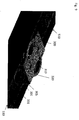

Classifications
-
- F—MECHANICAL ENGINEERING; LIGHTING; HEATING; WEAPONS; BLASTING
- F21—LIGHTING
- F21V—FUNCTIONAL FEATURES OR DETAILS OF LIGHTING DEVICES OR SYSTEMS THEREOF; STRUCTURAL COMBINATIONS OF LIGHTING DEVICES WITH OTHER ARTICLES, NOT OTHERWISE PROVIDED FOR
- F21V21/00—Supporting, suspending, or attaching arrangements for lighting devices; Hand grips
- F21V21/02—Wall, ceiling, or floor bases; Fixing pendants or arms to the bases
Definitions
- the present invention relates to a mounting arrangement for mounting a luminaire member to a luminaire holder.
- Prior art document FR 1 574 669 A discloses a mounting arrangement for mounting a luminaire wherein a first member is attached to a ceiling of a room which can be releasably combined with a second mounting element arranged within the luminaire. Further mounting arrangements are disclosed in US 6,682,036 B1 , US 2002/118545 A1 and FR 2 699 975 A1 .
- a mounting arrangement for mounting a luminaire member to a luminaire holder comprises a first mounting member, formed to be mounted to a luminaire holder and a second mounting member, formed to combine with the first mounting member releasably, wherein the second mounting member comprises accommodation means for accommodating the luminaire member.
- the inventive mounting arrangement further comprises a sealing member, arranged to be fitted to one of the mounting members, formed to seal the mounting arrangement, in particular one of the mounting members, water and/ or air-tight with the luminaire member, wherein the accommodation means of the second mounting member are arranged to form a snap-fitting or latching connection with the luminaire member, and one of the mounting members comprises snap-fitting or latching means formed to combine snap-fittingly the first mounting member with the second mounting member.
- the inventive arrangement is provided with a plurality of advantages. Involving two mounting members, the mounting process is divided into readily achievable steps, wherein a first step is represented by mounting a first mounting member to the luminaire holder, facilitated by the limited size and low weight of the first mounting member. A further step is given by combining a luminaire member to the first mounting member by means of the second mounting member, effectively mounting a luminaire member to the luminaire holder - aided by the inventive mounting arrangement. Obviously the fitting of a first mounting member to a luminaire holder can be handled by a single worker, obviating the support of a bulky luminaire.
- the first mounting member is formed to accommodate attaching means to attach the first mounting member to a luminaire holder.
- attaching means can be easily accommodated by arranging expedient openings, slots, channels or other guiding means in the respective first mounting member.
- the first mounting member comprises attaching means to attach the first mounting member to a luminaire holder.
- attaching means to attach the first mounting member to a luminaire holder.
- hook-like assemblies might be formed to combine with elements of a suspended ceiling, or clamping means might be arranged.
- the mounting arrangement is provided with the possibility to be moved with respect to the luminaire member, even while accommodating the luminaire member, and for example also while the luminaire member is latched or snap-fittingly combined to the mounting arrangement. This could be achieved for example by a combination, limiting movement preferably in one direction of restriction, whereas clearance for movement is provided advantageously in the plane normal to the direction of restriction.
- one of the mounting members comprises accommodation faces for accommodating the luminaire member form-fittingly, preferably obviating unnecessary limitations concerning the movement of the luminaire member with respect to the mounting arrangement.
- a slight margin remains in at least one direction, to provide the possibility to adapt the position of the luminaire member with respect to the mounting arrangement.
- the usage of tools can be obviated while combining the second mounting member to the first mounting member. Accordingly, the possibility to support the luminaire member two handed, while mounting the luminaire member to the luminaire holder emerges. Thus, a significant improvement in the mounting of luminaires is achieved, saving costs and efforts.
- one of the snap-fitting or latching means comprises a plurality of snap-fitting or latching positions, enhancing opportunity for various modifications in the spatial relation of luminaire member and luminaire holder.
- An alteration of the spatial relation for example can be gained by the choice of one of the plurality of snap-fitting or latching positions.
- the snap-fitting or latching means are arranged to provide an alteration in the distance of luminaire member and luminaire holder by the choice of an appropriate latching position. And further with providing a set of latching positions the possibility is raised to exhibit a predefined alteration procedure, adapting a complex lighting system to a variety of luminaire holders.
- one of the snap-fitting or latching means is arranged to lock the snap-fitting or latching means in one of the plurality of snap-fitting or latching positions. Fostering the possibility to adapt to various luminaire holders, a reliable spatial relation of luminaire member and luminaire holder is achieved.
- one of the snap-fitting or latching means combining the first mounting member with the second mounting member is formed at least in part as a thread or winding.
- a thread or winding provides a continuous set of latching positions for combining the first and the second mounting member, implicating all the benefits of a plurality of latching positions and further providing a very precise range of adjustment.
- the mounting arrangement can be adapted to various luminaire members and even to a variety of lamp holders providing a versatile use.
- one of the snap-fitting or latching means for combining the first mounting member with the second mounting member is arranged to perform a rotation with respect to the corresponding other snap-fitting or latching means, advantageously while being in a fitted state.
- said snap-fitting or latching means are arranged to lock by the rotation and unlock by a reversed rotation, facilitating the save and defined arrangement of the luminaire member with respect to the luminaire holder.
- one of the mounting members favorably the second mounting member, comprises a plurality of members.
- one of the mounting members comprises advantageously a first assembly member and a second assembly member, formed to combine snap-fittingly.
- the first and second assembly members are arranged rotatable with respect to each other while being snap-fittingly combined. This raises opportunity to suppress rotational movement of the luminaire member with respect to the corresponding mounting member, while at the same time a comprised assembly member is provided with the possibility to be rotated.
- the rotatable assembly member is combined to the latching or snap-fitting means of the corresponding mounting member and advantageously contributes to locking the combination.
- the mounting arrangement is formed to provide a combination of the luminaire member with the luminaire holder compliant to regulations for luminaires corresponding to a higher protection class, for example IP 01 and higher.
- the mounting arrangement comprises a sealing member, arranged to be fitted to one of the mounting members.
- the sealing member is formed to seal the mounting arrangement, preferably one of the mounting members, water- respectively air tight to the luminaire member.
- a further aspect of the invention is directed to a luminaire, comprising a luminaire member formed to be combined with a luminaire holder by a mounting arrangement according to the invention.
- the luminaire member is formed as a base plate.
- the base plate for example comprises snap-fitting or latching means, formed to combine the base plate with additional luminaire members.
- the snap-fitting or latching means for combining additional luminaire members to the base plate might be arranged in a hook-like form, favorably providing a snap-fitting face to combine with other luminaire members.
- the luminaire member comprises an opening, arranged to cooperate with the accommodation means.
- the luminaire member comprises one or a plurality of openings that are formed to suppress rotational movement of the luminaire with respect to the mounting arrangement.
- the accommodation means are formed to suppress rotational movement by a polygonal or oblong shape.
- the spatial relation of openings, preferably protruded by the accommodation means of the mounting arrangement is provided with the possibility to suppress rotation.
- a set of distant openings can be protruded with bolt-like accommodation means, suppressing rotational movement.
- the luminaire member in the case of openings cooperating with the accommodation means it is favorable to provide the luminaire member with snap-fitting faces adjacent the openings, which are more preferably formed to allow movement of the luminaire member while being snap-fittingly combined to the mounting arrangement.
- the mounting arrangement comprises an anti rotational bracket mounted between the first mounting member and the luminaire holder, preventing rotation of the mounting arrangement around the mounting point.
- the inventive mounting arrangement 1 comprises a first mounting member 100 and a second mounting member 200. Both mounting members 100 and 200 are lightweight and easy to handle, imposing preferably less than 250g of weight each.
- First Mounting member 100 is provided with the possibility to accommodate expedient attaching means 1001 for a variety of lamp holders 1000.
- an essentially pole-like or frusto-conical first mounting member 100 comprises a tubular central hole, to accommodate a variety of nails or screws, adapting to miscellaneous surfaces of lamp holders 1000.
- first mounting member 100 comprises oblong openings, rails or other guiding means to accommodate attaching means in an efficient manner.
- Figure 5 shows further modifications of the inventive mounting arrangement 1.
- First mounting member 100 comprises a circle like base plate 110, provided with oblong openings 111, for the accommodation of attaching means.
- the oblong shape of the openings 111 raises opportunity to vary the position of the first mounting member 100 with respect to the luminaire holder 1000.
- the first mounting member 100 might also comprise attaching means 1001, combining the first mounting member 100 with a ceiling, as an example of a lamp holder 1000.
- attaching means 1001 combining the first mounting member 100 with a ceiling, as an example of a lamp holder 1000.
- even a snap fitting of clamping connection to a rail system, a suspended ceiling or the like is conceivable.
- the first mounting member 100 as depicted in figure 5 comprises accommodation means 150, for accommodating the luminaire member 510, arranged to suppress rotational movement of the luminaire member 510 with respect to the first mounting member 100, by protruding sufficiently spaced openings in luminaire member 510.
- accommodation means 150 for accommodating the luminaire member 510, arranged to suppress rotational movement of the luminaire member 510 with respect to the first mounting member 100, by protruding sufficiently spaced openings in luminaire member 510.
- other means to suppress rotational movement of the luminaire member 510 are also conceivable.
- the first mounting member 100 comprises snap fitting means 130 to combine with the second mounting member 200.
- Embodiments of figures 1 to 5 show frusto-conical snap-fitting means 130, to be combined with the second mounting member 200, arranged in the center region of the circle like base plate 110.
- Advantageously snap-fitting means 130 are provided with a thread.
- the surface of the thread or winding 131 represents a plurality of essentially triangular snap-fitting faces, providing an almost unlimited set of latching positions.
- snap-fitting means 130 at least in part are formed as a thread or winding.
- the first mounting member 100 might be of predominantly conical or tapered shape, preferably of frusto-conical shape.
- snap-fitting means 130 are arranged to protrude respective openings of luminaire member 510, as depicted for example in figures 1 to 5 .
- the length of snap fitting means 130 determines the adaption range of the distance between luminaire member 510 and luminaire holder 1000.
- the snap-fitting means 130 are formed to provide an adjustment range of 1 to 100 mm of the distance of luminaire member 510 to luminaire holder 1000, for example a thread is provided in a corresponding length of 1 to 100 mm.
- the inventive mounting arrangement 1 comprises a second mounting member 200.
- first mounting member 100 serves as a base for combining with the second mounting member 200, effectively mounting a luminaire member 510 to the lamp holder 1000.
- the second mounting member 200 is provided with the possibility to swiftly combine with the first mounting member 100, advantageously obviating the use of tools. This creates the possibility to use both hands to support the luminaire member 510 or mounting members connected to it, while fitting the luminaire member to its operating position. Further the time spent to support heavy weights, as imposed by a luminaire 500 for example, is significantly reduced, fostering productivity of workers involved.
- luminaire member 510 is preferably combined with the second mounting member 200.
- the second mounting member 200 integrally with luminaire member 510.
- the second mounting member 200 is preferably formed as a separate member, provided with accommodation means 250 to accommodate a luminaire member 510, to be mounted to a lamp holder 1000.
- Embodiments of figures 1 to 4 sketch a second mounting member 200, provided with a plurality of accommodation means 250.
- the accommodation means 250 are formed to protrude openings 511, arranged in the luminaire member 510.
- rotation of the luminaire member 510 with respect to the second mounting member 200 is effectively suppressed.
- a suitable shape might comprise a polygonal or an oblong element.
- openings 511 exceed protrusions members 260 comprised in the accommodation means 250 in size, creating the possibility to slightly align the luminaire member 510 with respect to the second mounting member 200 and thus to the mounting arrangement 1, even in an accommodated state.
- the accommodation means 250 comprise snap-fitting means 255, in turn exceeding the openings 511 of luminaire member 510 in size.
- Snap-fitting means 255 are formed to resiliently pass through openings 511, subsequently snapping in place to provide a safe and reliable connection of the second mounting member 200 to the luminaire member 510, fostered by the conical shape of snap-fitting means 255 and edgewise mounting to pole-like protrusion members 260 in this embodiment of accommodation means 250.
- FIG. 5 Preferred embodiment of figure 5 comprises accommodation means 250 of essentially circular shape.
- Accommodation means 250 resiliently protrude an essentially circular opening provided in luminaire member 510.
- the opening protruded is of oblong shape, allowing for adaption of the position of the mounting arrangement 1 with respect to the luminaire member 510. Further, also for this case it is favorable to provide snap-fitting means 255 exceeding a minimal diameter of the opening protruded in size.
- snap fitting means 255, accommodation means 250 or the second mounting member 200 are preferably formed of an elastomer, supporting the resilient interaction of the snap-fitting means 255 with the luminaire member 510, but other resilient assemblies are also conceivable.
- the second mounting member 200 is provided with snap-fitting or latching means 230.
- second mounting member 200 is pressed onto the thread of the first mounting member 100.
- the first and second mounting members 100, 200 are formed to effectively avoid screw-like turning to snap the first and second mounting members 100, 200 into their latching position.
- snap-fitting means 230 comprise a winding 231, advantageously formed as a fraction of a winding 231.
- this can be achieved by slots 232 arranged in the preferably tubular snap-fitting means 230.
- Advantageously fractions of the winding 231 are arranged to latch with respective faces of a thread provided by the first mounting member 100.
- the invention is provided with other means to latch with faces of the thread, provided with the first mounting member.
- a ball bearing like assembly can be stipulated, wherein the respective balls latch with the thread.
- snap-fitting or latching means 130, 230 formed to bend resiliently, creates opportunity to advantageously allow for a clearance between snap-fitting means 130 and 230, enhancing the snap-fitting and latching possibilities and also facilitating the snap fitting process.
- the clearance might originate from a tapered shape of snap-fitting means 130, providing a stopping face for the snap-fitting means 230. In the embodiments of figures 1 to 5 this is achieved by a frusto-conical shape of snap-fitting means 130.
- FIG. 5 shows also a detailed view of a winding 231 provided in a preferred embodiment of a second mounting member 200.
- Second mounting member 200 is preferably formed of an elastomer or another material provided with sufficient flexibility to snap on snap-fitting or latching means 130, in this embodiment preferably a thread.
- Fractions of winding 231 are formed to bend resiliently obviating the need to use a turning technique to advance to a subsequent latching position.
- the resilient bending is fostered by a plurality of slots 232, in the depicted case a regular arrangement of four slots, separating fractions of a winding 231, allowing to bend the fractions of winding 231 resiliently.
- slots 232 lead to a ring shaped body of the second mounting member 200, which is representing a base element for mounting and accommodating preferably resilient snap-fitting or latching means 230.
- second mounting member 200 comprises a plurality of assembly members, in the embodiment of figures 1 to 4 , a first assembly member 210, a second assembly member 220 and the snap-fitting means 230.
- Fractions of a winding 231, separated entirely by slots 232, are fitted to an essentially triangular base frame 234, preferably integrally.
- Advantageously snap fitting or latching means 230 are formed of a resilient material, preferably an elastomer. Thickness of base frame 234 is advantageously thinner than the wall thickness of winding 231, forming a preferred resilient joint.
- Advantageously outer faces of winding 231 are formed to mate with first or second assembly member 210, 220 form-fittingly.
- first assembly member 210 is formed to combine snap-fittingly with second assembly member 220.
- Figure 3 depicts a second assembly member 220, comprising a base plate of parallelepiped shape - supporting a stable construction and providing the possibility to form accommodation means 250, suppressing rotational movement of the luminaire member 510 - and a ring-like snap-fitting face connected to the base plate.
- the snap-fitting face comprises a flange-like bulge, preferably serving as a bearing for the second assembly member 220.
- Second assembly member 220 is advantageously formed to combine with the first assembly member 210 snap-fittingly.
- second assembly member 220 comprises a bulge, formed to snap behind said bulge of assembly member 210 to complete the snap-fitting connection.
- the depicted snap-fitting connection is arranged to reliably and safely combine the first assembly member 210 with second assembly member 220 and moreover the first 210 and second assembly member 220 are provided with the possibility to be rotated with respect to each other, while being snap-fittingly connected.
- FIG. 4 shows a second assembly member 220 comprising additional guiding means, for accommodating snap-fitting means 230 arranged in the second mounting member 220. While being snap-fittingly connected, first and second assembly members 210, 220 enclose snap-fitting means 230. Accommodated by guiding means snap fitting means 230 can be rotated with respect to first assembly member 210 in combination with second assembly member 220.
- first and second mounting members 100, 200 can be rotated with respect to each other, preferably in a snap-fitted state.
- snap-fitting means 130 or 230 are arranged to lock by performing said rotation.
- with performing a rotation of the second mounting member 200 - and in particular of snap fitting means 230 - winding 231 of second mounting member 200 engages with the thread of first mounting member 100, locking the combination of snap-fitting means 130 and 230 in a latching position.
- Advantageously thread or winding 231 comprised in the second mounting member is provided with a pitch distinct from a thread or winding comprised in the first mounting member 100, also fostering a swift locking.
- a reliable latching position is achieved, providing a defined spatial relation of luminaire member 510 and luminaire holder 1000.
- Comprising a plurality of latching positions predominantly allowing a defined variation in the distance between luminaire member 510 and luminaire holder 1000, compensation of imperfections in the composition of a luminaire holder 1000 is facilitated. Slopes or the like can be balanced or, on the other hand can also be achieved, fostering a swift mounting as stipulated by the lighting design. Locking one of the mounting members 100, 200 in a latching position provides a reliable fitting of the luminaire member 510 to the luminaire holder 1000, inhibiting further unintended modifications.
- FIGS. 1 to 4 are arranged to unlock the snap-fitting or latching combination, allowing for the adjustment of a latching position, by simply reversing the rotation described above.
- An easy to use unlocking procedure, facilitating final adjustments significantly, contributes also in reducing installation efforts and costs.
- essentially circular second assembly member 220 comprises corrugations, preferably arranged at the perimeter, to support the grip of a hand, aiding rotational movement.
- corrugations are arranged on a bulge, jutting out of second mounting member 200.
- second mounting member 200 comprises two bulges to form accommodation means for a sealing member 280, in an example forming accommodation faces to provide a contact area for the sealing member with other members, preferably the luminaire member 510.
- the inventive mounting arrangement 1 comprises a sealing member 280, as shown for example in figure 6 .
- Sealing member 280 is preferably formed to snap form-fittingly on one of the first or second mounting members 100, 200, while maintaining the possibility to combine first and second mounting members 100, 200.
- the sealing member 280 is formed to seal the respective mounting member 100, 200 with the luminaire member 510 water- and preferably also air-tight, to aid the mounting of a luminaire compliant to a higher protection class, exceeding at least class IP01.
- Sealing member 280 as depicted in embodiment of figure 6 , is arranged to fit between the second mounting member 200 and luminaire member 510, allowing the engagement of accommodation means 250.
- sealing member 280 is mandatory, to allow the use of accommodation means 250.
- the arrangement of sealing member 280 between first or second mounting member 100, 200 and luminaire member 510 is supported by mentioned accommodation faces, providing a contact area for sealing member 280 and luminaire member 510.
- sealing member 280 is arranged between first or second mounting member 100, 200 and luminaire member 510.
- sealing member 280 is formed of a compressible material, preferably a resilient elastomer, a rubber or a foam material, to support the sealing and increase the contact area while being compressed between first or second mounting member 100, 200 and luminaire member 510.
- the sealing member 280 and the luminaire member 510 in combination are arranged to fully enclose a first or a second mounting member 100, 200 except of openings for accommodation means 250, attaching means 1001 or respective snap-fitting means 130, 230.
- Embodiment of figure 6 depicts second mounting member 200 fully enclosed by sealing member 280, wherein sealing member 280 is provided with an opening for accommodation means 250.
- Accommodation means 250 are arranged to combine snap-fittingly with luminaire member 510, compressing sealing member 280 between luminaire member 510 and second mounting member 200, while being snap-fittingly combined.
- sealing member 280 is formed to provide an air-tight sealing of luminaire member 510 with mounting member 200. The air tight sealing is achieved by compressing the sealing member 280 between luminaire member 510 and second mounting member 200, covering respective openings of luminaire member 510 entirely.
- a further aspect of the invention is directed to a luminaire 500 comprising a luminaire member 510 formed to be combined with a luminaire holder 1000 by a mounting arrangement 1 according to the invention.
- a luminaire 500 can be further facilitated by a luminaire member 510 formed as a base plate, as depicted in the embodiment of figure 2 or 4 .
- the respective luminaire member 510 comprises snap-fitting or latching means 512, for combining the base plate with additional luminaire members.
- snap-fitting or latching means 512 are arranged in a hook-like form, preferably cooperating with an oblong cover of the respective luminaire 500, also following the concept of readily achievable mounting steps.
- the luminaire member 510 formed as a base plate in the embodiment of figure 4 , comprises a plurality of openings 511, arranged to suppress rotational movement of the luminaire with respect to the inventive mounting arrangement 1.
- inventive mounting system 1 is provided with various benefits to facilitate the mounting of luminaire members 510 or luminaires 500 to a lamp holder 1000. Further, it is understood that according to the invention the combination of specific embodiments depicted as an example is not excluded.
- the mounting process is transformed to mounting steps effectively using and taking into account the capabilities of a single worker, thus resulting in a swift and precise mounting of a luminaire, improving installation time and effort.
- An anti rotational bracket 300 is mounted between the surface onto which the luminaire shall be mounted, e.g. the luminaire holder 1000, and a first mounting member 310.
- This mounting member 310 corresponds to the mounting member 100 from Fig. 5 .
- This anti rotational bracket comprises a mainly flat surface and four bracket legs 305. The bracket legs 305 extend beyond the surface of the anti rotational bracket 300 toward the direction of the luminaire. At the end of each bracket leg 305 a mounting clip 301 is formed by a bend in the bracket leg 305.
- the anti rotational bracket 300 furthermore comprises mains cable entries 302, direct fixing holes 304 and BESA fixing holes 303.
- the first mounting member 310 can be rotated when in position on the anti rotational bracket 300 in order to align fixing holes within the first mounting member 310 and the direct fixing holes 304 or the BESA fixing holes in the anti rotational bracket 300.
- the first mounting member 310 and the anti rotational bracket 300 are mounted to the surface, the luminaire shall be mounted to, e.g. using screws. This can easily be seen in Fig. 8 . Afterwards a luminaire member 510 connected to a second mounting member 320 is inserted.
- bracket legs 305 enter into mounting rails 331 on the surface of the luminaire member.
- the mounting clips 301 lock into position with the mounting rails 331.
- the anti rotational bracket 300 and the first mounting member 310 are held on the mounting surface by screws.
- the luminaire member 510 is held in position by the mounting clips 301 and the second mounting member 320 which connects to the first mounting member 310.
- the bracket legs 305 and the mounting clips 301 ensure a fixed position of the luminaire member 510. A rotation around the one point, it is fixed to is no longer possible.
- Fig. 10 finally shows the entire assembly of the mounting arrangement including a luminaire 600 mounted to the luminaire member 510. It can easily be seen that it is now possible to mount the luminaire at one single mounting point without the risk of unintended rotation.
Landscapes
- Engineering & Computer Science (AREA)
- General Engineering & Computer Science (AREA)
- Non-Portable Lighting Devices Or Systems Thereof (AREA)
Description
- The present invention relates to a mounting arrangement for mounting a luminaire member to a luminaire holder.
- Large lighting systems are customarily designed to exhibit a variety of lighting effects, using a plurality of cooperating luminaires. In order to achieve the desired overall lighting effect, an exact fitting of luminaires at a location corresponding to the lighting concept is mandatory. For a sufficiently large system this proves to be quite tedious, requiring a number of workers supporting each other, resulting in rapidly increasing installation costs.
- Exact alignment of the lighting means is frequently hampered by variations in the mounting face. Slight imperfections in the surface of a ceiling for example might result in an undesired tilting of a luminaire, thus putting the overall lighting effect into question. Time consuming adaptations of the mounting of a plurality of luminaires, involving in the worst case an iterated try and error method, are unavoidable in this case.
- Further, supporting large or heavy luminaires during installation is impossible for a single worker, proving a plurality of workers mandatory for explicit luminaire models.
- Therefore, an arrangement significantly reducing installation efforts and costs is favorable.
- Prior
art document FR 1 574 669 A US 6,682,036 B1 ,US 2002/118545 A1 andFR 2 699 975 A1 - It is an object of the present invention to further improve the mounting of a luminaire to a luminaire holder and to facilitate the respective mounting process, effectively reducing installation costs of luminaires.
- This object is solved by a mounting arrangement according to
claim 1. Advantageous modifications of the present invention are subject matter of the depending claims. - According to the invention a mounting arrangement for mounting a luminaire member to a luminaire holder is provided. The mounting arrangement comprises a first mounting member, formed to be mounted to a luminaire holder and a second mounting member, formed to combine with the first mounting member releasably, wherein the second mounting member comprises accommodation means for accommodating the luminaire member. The inventive mounting arrangement further comprises a sealing member, arranged to be fitted to one of the mounting members, formed to seal the mounting arrangement, in particular one of the mounting members, water and/ or air-tight with the luminaire member, wherein the accommodation means of the second mounting member are arranged to form a snap-fitting or latching connection with the luminaire member, and one of the mounting members comprises snap-fitting or latching means formed to combine snap-fittingly the first mounting member with the second mounting member.
- The inventive arrangement is provided with a plurality of advantages. Involving two mounting members, the mounting process is divided into readily achievable steps, wherein a first step is represented by mounting a first mounting member to the luminaire holder, facilitated by the limited size and low weight of the first mounting member. A further step is given by combining a luminaire member to the first mounting member by means of the second mounting member, effectively mounting a luminaire member to the luminaire holder - aided by the inventive mounting arrangement. Obviously the fitting of a first mounting member to a luminaire holder can be handled by a single worker, obviating the support of a bulky luminaire.
- Fostering the easy fitting to the luminaire holder, preferably the first mounting member is formed to accommodate attaching means to attach the first mounting member to a luminaire holder. For example, attaching means can be easily accommodated by arranging expedient openings, slots, channels or other guiding means in the respective first mounting member.
- Further, in an advantageous modification of the present invention, the first mounting member comprises attaching means to attach the first mounting member to a luminaire holder. For example, hook-like assemblies might be formed to combine with elements of a suspended ceiling, or clamping means might be arranged.
- In a preferred embodiment, the mounting arrangement is provided with the possibility to be moved with respect to the luminaire member, even while accommodating the luminaire member, and for example also while the luminaire member is latched or snap-fittingly combined to the mounting arrangement. This could be achieved for example by a combination, limiting movement preferably in one direction of restriction, whereas clearance for movement is provided advantageously in the plane normal to the direction of restriction.
- Advantageously, one of the mounting members comprises accommodation faces for accommodating the luminaire member form-fittingly, preferably obviating unnecessary limitations concerning the movement of the luminaire member with respect to the mounting arrangement. Favorably, a slight margin remains in at least one direction, to provide the possibility to adapt the position of the luminaire member with respect to the mounting arrangement.
- According to the present invention, the usage of tools can be obviated while combining the second mounting member to the first mounting member. Accordingly, the possibility to support the luminaire member two handed, while mounting the luminaire member to the luminaire holder emerges. Thus, a significant improvement in the mounting of luminaires is achieved, saving costs and efforts.
- Advantageously one of the snap-fitting or latching means comprises a plurality of snap-fitting or latching positions, enhancing opportunity for various modifications in the spatial relation of luminaire member and luminaire holder. An alteration of the spatial relation for example can be gained by the choice of one of the plurality of snap-fitting or latching positions. In a preferred embodiment the snap-fitting or latching means are arranged to provide an alteration in the distance of luminaire member and luminaire holder by the choice of an appropriate latching position. And further with providing a set of latching positions the possibility is raised to exhibit a predefined alteration procedure, adapting a complex lighting system to a variety of luminaire holders.
- Preferably, one of the snap-fitting or latching means is arranged to lock the snap-fitting or latching means in one of the plurality of snap-fitting or latching positions. Fostering the possibility to adapt to various luminaire holders, a reliable spatial relation of luminaire member and luminaire holder is achieved.
- In an advantageous modification of the present invention, one of the snap-fitting or latching means combining the first mounting member with the second mounting member is formed at least in part as a thread or winding. A thread or winding provides a continuous set of latching positions for combining the first and the second mounting member, implicating all the benefits of a plurality of latching positions and further providing a very precise range of adjustment. Thus, the mounting arrangement can be adapted to various luminaire members and even to a variety of lamp holders providing a versatile use.
- Further, the possibility is provided to compensate imperfections of the lamp holder surface by expedient choice of the latching position. Moreover, since a defined set of latching positions is given, mounting of the luminaire member on tilted surfaces is facilitated by mimicing the slope in the choice of respective latching positions.
- In a preferred embodiment of the present invention, one of the snap-fitting or latching means for combining the first mounting member with the second mounting member is arranged to perform a rotation with respect to the corresponding other snap-fitting or latching means, advantageously while being in a fitted state.
- Preferably said snap-fitting or latching means are arranged to lock by the rotation and unlock by a reversed rotation, facilitating the save and defined arrangement of the luminaire member with respect to the luminaire holder.
- In an advantageous modification of the invention one of the mounting members, favorably the second mounting member, comprises a plurality of members.
- In this case, one of the mounting members comprises advantageously a first assembly member and a second assembly member, formed to combine snap-fittingly. In a preferred embodiment the first and second assembly members are arranged rotatable with respect to each other while being snap-fittingly combined. This raises opportunity to suppress rotational movement of the luminaire member with respect to the corresponding mounting member, while at the same time a comprised assembly member is provided with the possibility to be rotated. In an advanced embodiment the rotatable assembly member is combined to the latching or snap-fitting means of the corresponding mounting member and advantageously contributes to locking the combination.
- Moreover, in an advantageous modification of the invention, the mounting arrangement is formed to provide a combination of the luminaire member with the luminaire holder compliant to regulations for luminaires corresponding to a higher protection class, for example IP 01 and higher. Preferably, the mounting arrangement comprises a sealing member, arranged to be fitted to one of the mounting members. Advantageously the sealing member is formed to seal the mounting arrangement, preferably one of the mounting members, water- respectively air tight to the luminaire member.
- A further aspect of the invention is directed to a luminaire, comprising a luminaire member formed to be combined with a luminaire holder by a mounting arrangement according to the invention.
- Preferably, the luminaire member is formed as a base plate. The base plate for example comprises snap-fitting or latching means, formed to combine the base plate with additional luminaire members.
- As an example, the snap-fitting or latching means for combining additional luminaire members to the base plate might be arranged in a hook-like form, favorably providing a snap-fitting face to combine with other luminaire members.
- Further, to facilitate the accommodation of the luminaire member, the luminaire member comprises an opening, arranged to cooperate with the accommodation means. Preferably, the luminaire member comprises one or a plurality of openings that are formed to suppress rotational movement of the luminaire with respect to the mounting arrangement.
- In a preferred embodiment, the accommodation means are formed to suppress rotational movement by a polygonal or oblong shape. And it is also conceivable that the spatial relation of openings, preferably protruded by the accommodation means of the mounting arrangement, is provided with the possibility to suppress rotation. For example a set of distant openings, can be protruded with bolt-like accommodation means, suppressing rotational movement.
- Moreover, in the case of openings cooperating with the accommodation means it is favorable to provide the luminaire member with snap-fitting faces adjacent the openings, which are more preferably formed to allow movement of the luminaire member while being snap-fittingly combined to the mounting arrangement.
- Even more preferably the mounting arrangement comprises an anti rotational bracket mounted between the first mounting member and the luminaire holder, preventing rotation of the mounting arrangement around the mounting point.
- In the following, the present invention and preferred embodiments thereof are explained in more detail with respect to the enclosed figure. It is shown in
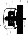
- Fig. 1
- an embodiment of an inventive mounting arrangement in a cross sectional view;
- Fig. 2
- the embodiment of
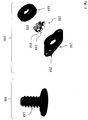
figure 1 in a perpendicular view; - Fig. 3
- a first and a second mounting member; wherein a mounting member comprises a plurality of members;
- Fig. 4
- an embodiment of a second mounting member and a corresponding luminaire member;
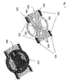
- Fig. 5
- further embodiments of the invention;
- Fig. 6
- a mounting arrangement, provided for luminaires with a higher protection class;
- Fig. 7
- an anti rotational bracket as part of an embodiment of the invention;
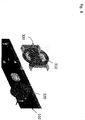
- Fig. 8
- an embodiment of a first mounting member with an anti rotational bracket;
- Fig. 9
- a mounting arrangement including an anti rotational bracket, and
- Fig. 10
- a mounting arrangement including a luminaire and an anti rotational bracket.
- The support of a
luminaire 500 of large dimensions or heavy weight for a substantial time while mounting it to aluminaire holder 1000 requires substantial efforts, and in the worst case a plurality of workers. Aided by the inventive mountingarrangement 1, this can be improved. - The
inventive mounting arrangement 1 comprises a first mountingmember 100 and a second mountingmember 200. Both mountingmembers - To mount a
luminaire member 510 to aluminaire holder 1000 using the inventive mountingarrangement 1, it is necessary to fit a first mountingmember 100 to theluminaire holder 1000. First Mountingmember 100 is provided with the possibility to accommodate expedient attachingmeans 1001 for a variety oflamp holders 1000. As shown in the embodiment offigure 1 , an essentially pole-like or frusto-conical first mountingmember 100, comprises a tubular central hole, to accommodate a variety of nails or screws, adapting to miscellaneous surfaces oflamp holders 1000. - Further, it is also conceivable, that the first mounting
member 100 comprises oblong openings, rails or other guiding means to accommodate attaching means in an efficient manner.Figure 5 shows further modifications of the inventive mountingarrangement 1. First mountingmember 100 comprises a circle likebase plate 110, provided withoblong openings 111, for the accommodation of attaching means. The oblong shape of theopenings 111 raises opportunity to vary the position of the first mountingmember 100 with respect to theluminaire holder 1000. - In a preferred modification of the invention the first mounting
member 100 might also comprise attachingmeans 1001, combining the first mountingmember 100 with a ceiling, as an example of alamp holder 1000. In a preferred embodiment, even a snap fitting of clamping connection to a rail system, a suspended ceiling or the like is conceivable. - In addition to the embodiments of
figures 1 to 4 , the first mountingmember 100 as depicted infigure 5 comprises accommodation means 150, for accommodating theluminaire member 510, arranged to suppress rotational movement of theluminaire member 510 with respect to the first mountingmember 100, by protruding sufficiently spaced openings inluminaire member 510. As will become obvious, other means to suppress rotational movement of theluminaire member 510 are also conceivable. - Preferably the first mounting
member 100 comprises snap fitting means 130 to combine with the second mountingmember 200. Embodiments offigures 1 to 5 show frusto-conical snap-fitting means 130, to be combined with the second mountingmember 200, arranged in the center region of the circle likebase plate 110. - Advantageously snap-fitting means 130 are provided with a thread. The surface of the thread or winding 131 represents a plurality of essentially triangular snap-fitting faces, providing an almost unlimited set of latching positions. Thus snap-fitting means 130, at least in part are formed as a thread or winding. To support the latching, the first mounting
member 100 might be of predominantly conical or tapered shape, preferably of frusto-conical shape. - In a preferred modification of the invention snap-fitting means 130 are arranged to protrude respective openings of
luminaire member 510, as depicted for example infigures 1 to 5 . Providing an expedient shape of the snap-fitting means in combination with adapted latching positions enhances the possibilities to adapt to a variety ofluminaire holders 1000. In the examples offigures 1 to 5 the length of snap fitting means 130 determines the adaption range of the distance betweenluminaire member 510 andluminaire holder 1000. Preferably the snap-fitting means 130 are formed to provide an adjustment range of 1 to 100 mm of the distance ofluminaire member 510 toluminaire holder 1000, for example a thread is provided in a corresponding length of 1 to 100 mm. - The
inventive mounting arrangement 1 comprises a second mountingmember 200. Mounted to theluminaire holder 1000, first mountingmember 100 serves as a base for combining with the second mountingmember 200, effectively mounting aluminaire member 510 to thelamp holder 1000. - The second mounting
member 200 is provided with the possibility to swiftly combine with the first mountingmember 100, advantageously obviating the use of tools. This creates the possibility to use both hands to support theluminaire member 510 or mounting members connected to it, while fitting the luminaire member to its operating position. Further the time spent to support heavy weights, as imposed by aluminaire 500 for example, is significantly reduced, fostering productivity of workers involved. - Accordingly,
luminaire member 510 is preferably combined with the second mountingmember 200. For certain luminaire models it is conceivable to form the second mountingmember 200 integrally withluminaire member 510. - However, the second mounting
member 200 is preferably formed as a separate member, provided with accommodation means 250 to accommodate aluminaire member 510, to be mounted to alamp holder 1000. - Embodiments of
figures 1 to 4 sketch a second mountingmember 200, provided with a plurality of accommodation means 250. As can be seen infigure 4 , the accommodation means 250 are formed to protrudeopenings 511, arranged in theluminaire member 510. With providing a plurality of protrudedopenings 511 in theluminaire member 510 rotation of theluminaire member 510 with respect to the second mountingmember 200 is effectively suppressed. However, it is conceivable that this is achieved also by an expedient shape of theopenings 511 or the protruding accommodation means 250. As an example, a suitable shape might comprise a polygonal or an oblong element. - Moreover
openings 511 exceedprotrusions members 260 comprised in the accommodation means 250 in size, creating the possibility to slightly align theluminaire member 510 with respect to the second mountingmember 200 and thus to the mountingarrangement 1, even in an accommodated state. - In the embodiment of
figure 1 the accommodation means 250, comprise snap-fitting means 255, in turn exceeding theopenings 511 ofluminaire member 510 in size. Snap-fitting means 255 are formed to resiliently pass throughopenings 511, subsequently snapping in place to provide a safe and reliable connection of the second mountingmember 200 to theluminaire member 510, fostered by the conical shape of snap-fitting means 255 and edgewise mounting to pole-like protrusion members 260 in this embodiment of accommodation means 250. - Preferred embodiment of
figure 5 comprises accommodation means 250 of essentially circular shape. Accommodation means 250 resiliently protrude an essentially circular opening provided inluminaire member 510. Snap-fitting means 255 integral to accommodation means 250, formed as snap-fitting faces jutting out the perimeter of circular accommodation means 250, exceed the minimal diameter of the respective opening protruded in size, thus providing a snap-fitting combination with theluminaire member 510. - In a preferred embodiment it is also conceivable that the opening protruded is of oblong shape, allowing for adaption of the position of the mounting
arrangement 1 with respect to theluminaire member 510. Further, also for this case it is favorable to provide snap-fitting means 255 exceeding a minimal diameter of the opening protruded in size. - Moreover, in a preferred modification of the invention sufficient clearance is provided by snap-fitting faces, arranged adjacent to
openings 511. Snap fitting means 255, accommodation means 250 or the second mountingmember 200 are preferably formed of an elastomer, supporting the resilient interaction of the snap-fitting means 255 with theluminaire member 510, but other resilient assemblies are also conceivable. - To combine the first and second mounting
member member 200 is provided with snap-fitting or latching means 230. In the embodiments offigures 1 to 5 , second mountingmember 200 is pressed onto the thread of the first mountingmember 100. Advantageously the first and second mountingmembers members - Preferably snap-fitting means 230 comprise a winding 231, advantageously formed as a fraction of a winding 231. As an example this can be achieved by
slots 232 arranged in the preferably tubular snap-fitting means 230. Supporting the latching of the snap-fitting means 230, preferably theslots 232 provide a clearance is for resilient movement of fractions of the winding. Advantageously fractions of the winding 231 are arranged to latch with respective faces of a thread provided by the first mountingmember 100. - However, it is also conceivable that the invention is provided with other means to latch with faces of the thread, provided with the first mounting member. For example, a ball bearing like assembly can be stipulated, wherein the respective balls latch with the thread.
- Providing snap-fitting or latching means 130, 230 formed to bend resiliently, creates opportunity to advantageously allow for a clearance between snap-fitting means 130 and 230, enhancing the snap-fitting and latching possibilities and also facilitating the snap fitting process. Advantageously the clearance might originate from a tapered shape of snap-fitting means 130, providing a stopping face for the snap-fitting means 230. In the embodiments of
figures 1 to 5 this is achieved by a frusto-conical shape of snap-fitting means 130. -
Figure 5 shows also a detailed view of a winding 231 provided in a preferred embodiment of a second mountingmember 200. Second mountingmember 200 is preferably formed of an elastomer or another material provided with sufficient flexibility to snap on snap-fitting or latching means 130, in this embodiment preferably a thread. Fractions of winding 231 are formed to bend resiliently obviating the need to use a turning technique to advance to a subsequent latching position. The resilient bending is fostered by a plurality ofslots 232, in the depicted case a regular arrangement of four slots, separating fractions of a winding 231, allowing to bend the fractions of winding 231 resiliently. In thisembodiment slots 232 lead to a ring shaped body of the second mountingmember 200, which is representing a base element for mounting and accommodating preferably resilient snap-fitting or latching means 230. - In the embodiments of
figures 1 to 4 snap-fitting or latching means 230 are arranged as a separate member of the second mountingmember 230. Preferably second mountingmember 200 comprises a plurality of assembly members, in the embodiment offigures 1 to 4 , afirst assembly member 210, asecond assembly member 220 and the snap-fitting means 230. - Fractions of a winding 231, separated entirely by
slots 232, are fitted to an essentiallytriangular base frame 234, preferably integrally. Advantageously snap fitting or latching means 230 are formed of a resilient material, preferably an elastomer. Thickness ofbase frame 234 is advantageously thinner than the wall thickness of winding 231, forming a preferred resilient joint. Advantageously outer faces of winding 231 are formed to mate with first orsecond assembly member - As can be seen in embodiments of
figure 1 to 4 ,first assembly member 210 is formed to combine snap-fittingly withsecond assembly member 220. Clarifying this,Figure 3 depicts asecond assembly member 220, comprising a base plate of parallelepiped shape - supporting a stable construction and providing the possibility to form accommodation means 250, suppressing rotational movement of the luminaire member 510 - and a ring-like snap-fitting face connected to the base plate. The snap-fitting face comprises a flange-like bulge, preferably serving as a bearing for thesecond assembly member 220. -
Second assembly member 220 is advantageously formed to combine with thefirst assembly member 210 snap-fittingly. Preferably being of essentially ring-shaped form,second assembly member 220 comprises a bulge, formed to snap behind said bulge ofassembly member 210 to complete the snap-fitting connection. - The depicted snap-fitting connection is arranged to reliably and safely combine the
first assembly member 210 withsecond assembly member 220 and moreover the first 210 andsecond assembly member 220 are provided with the possibility to be rotated with respect to each other, while being snap-fittingly connected. - Preferred embodiment of
figure 4 shows asecond assembly member 220 comprising additional guiding means, for accommodating snap-fitting means 230 arranged in the second mountingmember 220. While being snap-fittingly connected, first andsecond assembly members first assembly member 210 in combination withsecond assembly member 220. - Advantageously first and second mounting
members figures 1 to 5 , with performing a rotation of the second mounting member 200 - and in particular of snap fitting means 230 - winding 231 of second mountingmember 200 engages with the thread of first mountingmember 100, locking the combination of snap-fitting means 130 and 230 in a latching position. Advantageously thread or winding 231 comprised in the second mounting member is provided with a pitch distinct from a thread or winding comprised in the first mountingmember 100, also fostering a swift locking. - Thus, a reliable latching position is achieved, providing a defined spatial relation of
luminaire member 510 andluminaire holder 1000. Comprising a plurality of latching positions, predominantly allowing a defined variation in the distance betweenluminaire member 510 andluminaire holder 1000, compensation of imperfections in the composition of aluminaire holder 1000 is facilitated. Slopes or the like can be balanced or, on the other hand can also be achieved, fostering a swift mounting as stipulated by the lighting design. Locking one of the mountingmembers luminaire member 510 to theluminaire holder 1000, inhibiting further unintended modifications. - However, the embodiments of
figures 1 to 4 are arranged to unlock the snap-fitting or latching combination, allowing for the adjustment of a latching position, by simply reversing the rotation described above. An easy to use unlocking procedure, facilitating final adjustments significantly, contributes also in reducing installation efforts and costs. - Further, in the embodiments of
figures 1 to 5 , essentially circularsecond assembly member 220 comprises corrugations, preferably arranged at the perimeter, to support the grip of a hand, aiding rotational movement. - In one of the embodiments of
figure 5 , corrugations are arranged on a bulge, jutting out of second mountingmember 200. Preferably second mountingmember 200 comprises two bulges to form accommodation means for a sealingmember 280, in an example forming accommodation faces to provide a contact area for the sealing member with other members, preferably theluminaire member 510. - Advantageously the inventive mounting
arrangement 1 comprises a sealingmember 280, as shown for example infigure 6 . Sealingmember 280 is preferably formed to snap form-fittingly on one of the first or second mountingmembers members member 280 is formed to seal the respective mountingmember luminaire member 510 water- and preferably also air-tight, to aid the mounting of a luminaire compliant to a higher protection class, exceeding at least class IP01. Sealingmember 280, as depicted in embodiment offigure 6 , is arranged to fit between the second mountingmember 200 andluminaire member 510, allowing the engagement of accommodation means 250. It is understood that an expedient thickness of the sealingmember 280 is mandatory, to allow the use of accommodation means 250. The arrangement of sealingmember 280 between first or second mountingmember luminaire member 510 is supported by mentioned accommodation faces, providing a contact area for sealingmember 280 andluminaire member 510. - Preferably the sealing
member 280 is arranged between first or second mountingmember luminaire member 510. Thus, in an advantageous modification of the invention, sealingmember 280 is formed of a compressible material, preferably a resilient elastomer, a rubber or a foam material, to support the sealing and increase the contact area while being compressed between first or second mountingmember luminaire member 510. Advantageously the sealingmember 280 and theluminaire member 510 in combination are arranged to fully enclose a first or a second mountingmember means 1001 or respective snap-fitting means 130, 230. - Embodiment of
figure 6 depicts second mountingmember 200 fully enclosed by sealingmember 280, wherein sealingmember 280 is provided with an opening for accommodation means 250. Accommodation means 250 are arranged to combine snap-fittingly withluminaire member 510, compressing sealingmember 280 betweenluminaire member 510 and second mountingmember 200, while being snap-fittingly combined. Furthermore, sealingmember 280 is formed to provide an air-tight sealing ofluminaire member 510 with mountingmember 200. The air tight sealing is achieved by compressing the sealingmember 280 betweenluminaire member 510 and second mountingmember 200, covering respective openings ofluminaire member 510 entirely. - A further aspect of the invention is directed to a
luminaire 500 comprising aluminaire member 510 formed to be combined with aluminaire holder 1000 by a mountingarrangement 1 according to the invention. - Benefiting from the inventive mounting
arrangement 1, mounting of aluminaire 500 can be further facilitated by aluminaire member 510 formed as a base plate, as depicted in the embodiment offigure 2 or4 . Therespective luminaire member 510 comprises snap-fitting or latching means 512, for combining the base plate with additional luminaire members. In the embodiment offigure 4 snap-fitting or latching means 512 are arranged in a hook-like form, preferably cooperating with an oblong cover of therespective luminaire 500, also following the concept of readily achievable mounting steps. - Further, the
luminaire member 510, formed as a base plate in the embodiment offigure 4 , comprises a plurality ofopenings 511, arranged to suppress rotational movement of the luminaire with respect to the inventive mountingarrangement 1. - It is obvious that the
inventive mounting system 1 is provided with various benefits to facilitate the mounting ofluminaire members 510 orluminaires 500 to alamp holder 1000. Further, it is understood that according to the invention the combination of specific embodiments depicted as an example is not excluded. - With the aid of the inventive mounting
arrangement 1 the mounting process is transformed to mounting steps effectively using and taking into account the capabilities of a single worker, thus resulting in a swift and precise mounting of a luminaire, improving installation time and effort. - If it is desired to mount the luminaire using only one point the problem of rotational stability around the one point arises. In a further embodiment of the present invention shown in
Fig. 7 - Fig. 9 a solution to this problem is shown. - An anti
rotational bracket 300 is mounted between the surface onto which the luminaire shall be mounted, e.g. theluminaire holder 1000, and a first mountingmember 310. This mountingmember 310 corresponds to the mountingmember 100 fromFig. 5 . This anti rotational bracket comprises a mainly flat surface and fourbracket legs 305. Thebracket legs 305 extend beyond the surface of the antirotational bracket 300 toward the direction of the luminaire. At the end of each bracket leg 305 a mountingclip 301 is formed by a bend in thebracket leg 305. - The anti
rotational bracket 300 furthermore comprisesmains cable entries 302, direct fixingholes 304 and BESA fixing holes 303. - The first mounting
member 310 can be rotated when in position on the antirotational bracket 300 in order to align fixing holes within the first mountingmember 310 and the direct fixing holes 304 or the BESA fixing holes in the antirotational bracket 300. - The first mounting
member 310 and the antirotational bracket 300 are mounted to the surface, the luminaire shall be mounted to, e.g. using screws. This can easily be seen inFig. 8 . Afterwards aluminaire member 510 connected to a second mountingmember 320 is inserted. - As can easily be seen in
Fig. 9 thebracket legs 305 enter into mountingrails 331 on the surface of the luminaire member. The mountingclips 301 lock into position with the mounting rails 331. The antirotational bracket 300 and the first mountingmember 310 are held on the mounting surface by screws. Theluminaire member 510 is held in position by the mountingclips 301 and the second mountingmember 320 which connects to the first mountingmember 310. - The
bracket legs 305 and the mountingclips 301 ensure a fixed position of theluminaire member 510. A rotation around the one point, it is fixed to is no longer possible. -
Fig. 10 finally shows the entire assembly of the mounting arrangement including aluminaire 600 mounted to theluminaire member 510. It can easily be seen that it is now possible to mount the luminaire at one single mounting point without the risk of unintended rotation.
Claims (15)
- Mounting arrangement (1) for mounting a luminaire member (510) to a luminaire holder (1000),
comprising a• first mounting member (100, 310), formed to be mounted to a luminaire holder (1000) and a• second mounting member (200, 320), formed to combine with the first mounting member (100, 310) releasably, said second mounting member (200) comprising accommodation means (250) for accommodating the luminaire member (510),wherein the mounting arrangement (1) comprises a sealing member (280), arranged to be fitted to one of the mounting members, formed to seal the mounting arrangement (1), in particular one of the mounting members (100, 200), water and/ or air-tight with the luminaire member (510),
wherein the accommodation means (250) of the second mounting member (200) are arranged to form a snap-fitting or latching connection with the luminaire member (510), and
wherein one of the mounting members (100, 200) comprises snap-fitting or latching means (130, 230) formed to combine snap-fittingly the first mounting member (100) with the second mounting member (200). - Mounting arrangement (1) according to claim 1,
characterized in that
the first mounting member (100, 310) is formed to accommodate attaching means (1001) to attach the first mounting member (100, 310) to a luminaire holder (1000). - Mounting arrangement (1) according to any preceding claim, characterized in that
the first mounting member (100, 310) comprises attaching means (1001) to attach the first mounting member (100, 310) to a luminaire holder (1000). - Mounting arrangement (1) according to any preceding claim, characterized in that
one of the snap-fitting or latching means (130, 230) comprises a plurality of snap-fitting or latching positions, wherein in particular the snap-fitting or latching means (130, 230) are arranged to combine with each other by latching to one of the plurality of snap-fitting or latching positions. - Mounting arrangement (1) according to claim 4,
characterized in that
one of the snap-fitting or latching means (130, 230) is arranged to lock the snap-fitting or latching means (130, 230) in one of the plurality of snap-fitting or latching positions. - Mounting arrangement (1) according to any preceding claim, characterized in that
one of the snap-fitting or latching means (130, 230) to combine the first mounting member (100, 310) with the second mounting member (200, 320) is formed at least in part as a thread or winding. - Mounting arrangement (1) according to any preceding claim, characterized in that
one of the snap-fitting or latching means (130, 230) to combine the first mounting member (100, 310) with the second mounting member (200, 320) is arranged to perform a rotation with respect to the other snap-fitting or latching means (130, 230) while being in a fitted state. - Mounting arrangement (1) according to claim 7,
characterized in that
one of the snap-fitting or latching means (130, 230) to combine the first mounting member (100, 310) with the second mounting member (200, 320) is arranged to lock by the rotation and unlock by a reversed rotation. - Mounting arrangement (1) according to any preceding claim, characterized in that
one of the mounting members (100, 200, 310, 320), in particular the second mounting member (200, 320), comprises a plurality of members. - Mounting arrangement (1) according to claim 10,
characterized in that
one of the mounting members (100, 200, 310, 320) comprises a first assembly member (210) and a second assembly member (220), wherein the first (210) and second assembly member (220) are formed to combine snap-fittingly, and in particular, both assembly members (210, 220) are arranged rotatable with respect to each other while being snap-fittingly combined. - Mounting arrangement (1) according to any preceding claim, characterized in that
the mounting arrangement (1) comprises an anti rotational bracket (300) mounted between the luminaire holder (1000) and the first mounting member (310), and
that the anti rotational bracket (300) prevents the luminaire member (510) from rotating around the first mounting member (310). - Mounting arrangement (1) according to claim 11,
characterized in that
the anti rotational bracket (300) comprises bracket legs (305),
that the bracket legs (305) comprise mounting clips (301), and in that the mounting clips (301) connect to mounting rails (331) comprised by the luminaire member (510). - Luminaire (500),
characterized in that
the luminaire (500) comprises a luminaire member (510) formed to be combined with a luminaire holder (1000) by a mounting arrangement (1) according to any preceding claim. - Luminaire according to claim 13,
characterized in that
the luminaire member (510) is formed as a base plate, in particular comprising snap-fitting or latching means (512), for combining the base plate with additional luminaire members. - Luminaire according to any preceding claim 13 or 14,
characterized in that
the luminaire member (510) comprises openings (511) arranged to cooperate with one of the first or second mounting members (100, 200, 310, 320) in particular suppressing rotational movement of the luminaire (500) with respect to the mounting arrangement (1).
Priority Applications (1)
| Application Number | Priority Date | Filing Date | Title |
|---|---|---|---|
| EP10275104.7A EP2375145B1 (en) | 2010-04-09 | 2010-10-04 | Mounting arrangement |
Applications Claiming Priority (2)
| Application Number | Priority Date | Filing Date | Title |
|---|---|---|---|
| EP10250746A EP2375144A1 (en) | 2010-04-09 | 2010-04-09 | Mounting arrangement |
| EP10275104.7A EP2375145B1 (en) | 2010-04-09 | 2010-10-04 | Mounting arrangement |
Publications (2)
| Publication Number | Publication Date |
|---|---|
| EP2375145A1 EP2375145A1 (en) | 2011-10-12 |
| EP2375145B1 true EP2375145B1 (en) | 2020-06-03 |
Family
ID=42671935
Family Applications (2)
| Application Number | Title | Priority Date | Filing Date |
|---|---|---|---|
| EP10250746A Withdrawn EP2375144A1 (en) | 2010-04-09 | 2010-04-09 | Mounting arrangement |
| EP10275104.7A Active EP2375145B1 (en) | 2010-04-09 | 2010-10-04 | Mounting arrangement |
Family Applications Before (1)
| Application Number | Title | Priority Date | Filing Date |
|---|---|---|---|
| EP10250746A Withdrawn EP2375144A1 (en) | 2010-04-09 | 2010-04-09 | Mounting arrangement |
Country Status (1)
| Country | Link |
|---|---|
| EP (2) | EP2375144A1 (en) |
Family Cites Families (5)
| Publication number | Priority date | Publication date | Assignee | Title |
|---|---|---|---|---|
| NL6610783A (en) * | 1966-07-30 | 1968-01-31 | ||
| FR2699975B1 (en) * | 1992-12-29 | 1995-11-03 | Sarlam | SUPPORT OR FIXING DEVICE, PARTICULARLY FOR LUMINAIRES. |
| FR2702032B1 (en) * | 1993-02-24 | 1995-07-07 | Philips Eclairage | DEVICE FOR FIXING A LUMINAIRE ON A CONNECTION BOX AND LUMINAIRE PROVIDED WITH THIS DEVICE. |
| US6595664B2 (en) * | 2001-02-23 | 2003-07-22 | King Of Fans, Inc. | Quick-install, flush-mount bracket for light and other fixtures |
| US6682036B1 (en) * | 2003-02-28 | 2004-01-27 | Dong Guan Bright Yin Huey Lighting Co., Ltd. | Ceiling fixture |
-
2010
- 2010-04-09 EP EP10250746A patent/EP2375144A1/en not_active Withdrawn
- 2010-10-04 EP EP10275104.7A patent/EP2375145B1/en active Active
Non-Patent Citations (1)
| Title |
|---|
| None * |
Also Published As
| Publication number | Publication date |
|---|---|
| EP2375145A1 (en) | 2011-10-12 |
| EP2375144A1 (en) | 2011-10-12 |
Similar Documents
| Publication | Publication Date | Title |
|---|---|---|
| KR102472473B1 (en) | Fitting for channel framing | |
| US20200305596A1 (en) | Prefabricated shelf assembly | |
| US9310036B1 (en) | Retrofit mounting device for open frame ceiling | |
| US9726339B2 (en) | Luminaire, assembly for a grid ceiling, method for installing a luminaire, method for removing a luminaire, and removal tool | |
| EP2400210A9 (en) | Lighting System | |
| US20080192490A1 (en) | Recessed Lighting Fixture with Alignment Enhancements and Methods for Mounting Same | |
| US11754235B2 (en) | Lighting system and structures and apparatus related thereto | |
| US10012008B2 (en) | Installation body for door and/or window handles and handle arrangement with one installation body | |
| CA3079885C (en) | Lighting module assembly and method of use | |
| CA2161856C (en) | Track mounting clip for a track lighting system | |
| US20180328368A1 (en) | Connector for electrical devices | |
| CA2853010A1 (en) | Led retrofit removable trims and led recessed light kit with removable trim | |
| KR200451651Y1 (en) | Cover removal structure of luminaire | |
| EP2375145A1 (en) | Mounting arrangement | |
| KR101149783B1 (en) | A lower plate easy to assemble duct | |
| KR200458543Y1 (en) | Fix clip of ciling lamp | |
| US20150354243A1 (en) | Kit for mounting one or more appliances on a pole | |
| CN204141416U (en) | A kind of recessed light fixture | |
| JP2012195146A (en) | Lighting fixture mounting device | |
| GB2577934A (en) | Fitting assembly | |
| US10168034B2 (en) | Downlight | |
| US9404643B2 (en) | One piece LED module with rotatable face | |
| KR101162580B1 (en) | Leg of sink | |
| RU2672293C1 (en) | Roofing support (options) | |
| AU2011100925A4 (en) | Improvements in Downlight Fixtures |
Legal Events
| Date | Code | Title | Description |
|---|---|---|---|
| PUAI | Public reference made under article 153(3) epc to a published international application that has entered the european phase |
Free format text: ORIGINAL CODE: 0009012 |
|
| AK | Designated contracting states |
Kind code of ref document: A1 Designated state(s): AL AT BE BG CH CY CZ DE DK EE ES FI FR GB GR HR HU IE IS IT LI LT LU LV MC MK MT NL NO PL PT RO RS SE SI SK SM TR |
|
| AX | Request for extension of the european patent |
Extension state: BA ME |
|
| 17P | Request for examination filed |
Effective date: 20120412 |
|
| STAA | Information on the status of an ep patent application or granted ep patent |
Free format text: STATUS: EXAMINATION IS IN PROGRESS |
|
| 17Q | First examination report despatched |
Effective date: 20181122 |
|
| GRAP | Despatch of communication of intention to grant a patent |
Free format text: ORIGINAL CODE: EPIDOSNIGR1 |
|
| STAA | Information on the status of an ep patent application or granted ep patent |
Free format text: STATUS: GRANT OF PATENT IS INTENDED |
|
| RAP1 | Party data changed (applicant data changed or rights of an application transferred) |
Owner name: THORN LIGHTING LIMITED |
|
| INTG | Intention to grant announced |
Effective date: 20200210 |
|
| GRAS | Grant fee paid |
Free format text: ORIGINAL CODE: EPIDOSNIGR3 |
|
| GRAA | (expected) grant |
Free format text: ORIGINAL CODE: 0009210 |
|
| STAA | Information on the status of an ep patent application or granted ep patent |
Free format text: STATUS: THE PATENT HAS BEEN GRANTED |
|
| AK | Designated contracting states |
Kind code of ref document: B1 Designated state(s): AL AT BE BG CH CY CZ DE DK EE ES FI FR GB GR HR HU IE IS IT LI LT LU LV MC MK MT NL NO PL PT RO RS SE SI SK SM TR |
|
| REG | Reference to a national code |
Ref country code: GB Ref legal event code: FG4D |
|
| REG | Reference to a national code |
Ref country code: CH Ref legal event code: EP Ref country code: CH Ref legal event code: NV Representative=s name: VALIPAT S.A. C/O BOVARD SA NEUCHATEL, CH Ref country code: AT Ref legal event code: REF Ref document number: 1277377 Country of ref document: AT Kind code of ref document: T Effective date: 20200615 |
|
| REG | Reference to a national code |
Ref country code: DE Ref legal event code: R096 Ref document number: 602010064515 Country of ref document: DE |
|
| REG | Reference to a national code |
Ref country code: LT Ref legal event code: MG4D |
|
| PG25 | Lapsed in a contracting state [announced via postgrant information from national office to epo] |
Ref country code: LT Free format text: LAPSE BECAUSE OF FAILURE TO SUBMIT A TRANSLATION OF THE DESCRIPTION OR TO PAY THE FEE WITHIN THE PRESCRIBED TIME-LIMIT Effective date: 20200603 Ref country code: NO Free format text: LAPSE BECAUSE OF FAILURE TO SUBMIT A TRANSLATION OF THE DESCRIPTION OR TO PAY THE FEE WITHIN THE PRESCRIBED TIME-LIMIT Effective date: 20200903 Ref country code: SE Free format text: LAPSE BECAUSE OF FAILURE TO SUBMIT A TRANSLATION OF THE DESCRIPTION OR TO PAY THE FEE WITHIN THE PRESCRIBED TIME-LIMIT Effective date: 20200603 Ref country code: GR Free format text: LAPSE BECAUSE OF FAILURE TO SUBMIT A TRANSLATION OF THE DESCRIPTION OR TO PAY THE FEE WITHIN THE PRESCRIBED TIME-LIMIT Effective date: 20200904 Ref country code: FI Free format text: LAPSE BECAUSE OF FAILURE TO SUBMIT A TRANSLATION OF THE DESCRIPTION OR TO PAY THE FEE WITHIN THE PRESCRIBED TIME-LIMIT Effective date: 20200603 |
|
| REG | Reference to a national code |
Ref country code: NL Ref legal event code: MP Effective date: 20200603 |
|
| PG25 | Lapsed in a contracting state [announced via postgrant information from national office to epo] |
Ref country code: RS Free format text: LAPSE BECAUSE OF FAILURE TO SUBMIT A TRANSLATION OF THE DESCRIPTION OR TO PAY THE FEE WITHIN THE PRESCRIBED TIME-LIMIT Effective date: 20200603 Ref country code: HR Free format text: LAPSE BECAUSE OF FAILURE TO SUBMIT A TRANSLATION OF THE DESCRIPTION OR TO PAY THE FEE WITHIN THE PRESCRIBED TIME-LIMIT Effective date: 20200603 Ref country code: LV Free format text: LAPSE BECAUSE OF FAILURE TO SUBMIT A TRANSLATION OF THE DESCRIPTION OR TO PAY THE FEE WITHIN THE PRESCRIBED TIME-LIMIT Effective date: 20200603 Ref country code: BG Free format text: LAPSE BECAUSE OF FAILURE TO SUBMIT A TRANSLATION OF THE DESCRIPTION OR TO PAY THE FEE WITHIN THE PRESCRIBED TIME-LIMIT Effective date: 20200903 |
|
| PG25 | Lapsed in a contracting state [announced via postgrant information from national office to epo] |
Ref country code: AL Free format text: LAPSE BECAUSE OF FAILURE TO SUBMIT A TRANSLATION OF THE DESCRIPTION OR TO PAY THE FEE WITHIN THE PRESCRIBED TIME-LIMIT Effective date: 20200603 Ref country code: NL Free format text: LAPSE BECAUSE OF FAILURE TO SUBMIT A TRANSLATION OF THE DESCRIPTION OR TO PAY THE FEE WITHIN THE PRESCRIBED TIME-LIMIT Effective date: 20200603 |
|
| PG25 | Lapsed in a contracting state [announced via postgrant information from national office to epo] |
Ref country code: RO Free format text: LAPSE BECAUSE OF FAILURE TO SUBMIT A TRANSLATION OF THE DESCRIPTION OR TO PAY THE FEE WITHIN THE PRESCRIBED TIME-LIMIT Effective date: 20200603 Ref country code: CZ Free format text: LAPSE BECAUSE OF FAILURE TO SUBMIT A TRANSLATION OF THE DESCRIPTION OR TO PAY THE FEE WITHIN THE PRESCRIBED TIME-LIMIT Effective date: 20200603 Ref country code: PT Free format text: LAPSE BECAUSE OF FAILURE TO SUBMIT A TRANSLATION OF THE DESCRIPTION OR TO PAY THE FEE WITHIN THE PRESCRIBED TIME-LIMIT Effective date: 20201006 Ref country code: ES Free format text: LAPSE BECAUSE OF FAILURE TO SUBMIT A TRANSLATION OF THE DESCRIPTION OR TO PAY THE FEE WITHIN THE PRESCRIBED TIME-LIMIT Effective date: 20200603 Ref country code: IT Free format text: LAPSE BECAUSE OF FAILURE TO SUBMIT A TRANSLATION OF THE DESCRIPTION OR TO PAY THE FEE WITHIN THE PRESCRIBED TIME-LIMIT Effective date: 20200603 Ref country code: EE Free format text: LAPSE BECAUSE OF FAILURE TO SUBMIT A TRANSLATION OF THE DESCRIPTION OR TO PAY THE FEE WITHIN THE PRESCRIBED TIME-LIMIT Effective date: 20200603 Ref country code: SM Free format text: LAPSE BECAUSE OF FAILURE TO SUBMIT A TRANSLATION OF THE DESCRIPTION OR TO PAY THE FEE WITHIN THE PRESCRIBED TIME-LIMIT Effective date: 20200603 |
|
| PGFP | Annual fee paid to national office [announced via postgrant information from national office to epo] |
Ref country code: AT Payment date: 20201021 Year of fee payment: 11 |
|
| PG25 | Lapsed in a contracting state [announced via postgrant information from national office to epo] |
Ref country code: PL Free format text: LAPSE BECAUSE OF FAILURE TO SUBMIT A TRANSLATION OF THE DESCRIPTION OR TO PAY THE FEE WITHIN THE PRESCRIBED TIME-LIMIT Effective date: 20200603 Ref country code: SK Free format text: LAPSE BECAUSE OF FAILURE TO SUBMIT A TRANSLATION OF THE DESCRIPTION OR TO PAY THE FEE WITHIN THE PRESCRIBED TIME-LIMIT Effective date: 20200603 Ref country code: IS Free format text: LAPSE BECAUSE OF FAILURE TO SUBMIT A TRANSLATION OF THE DESCRIPTION OR TO PAY THE FEE WITHIN THE PRESCRIBED TIME-LIMIT Effective date: 20201003 |
|
| REG | Reference to a national code |
Ref country code: DE Ref legal event code: R097 Ref document number: 602010064515 Country of ref document: DE |
|
| PLBE | No opposition filed within time limit |
Free format text: ORIGINAL CODE: 0009261 |
|
| STAA | Information on the status of an ep patent application or granted ep patent |
Free format text: STATUS: NO OPPOSITION FILED WITHIN TIME LIMIT |
|
| PG25 | Lapsed in a contracting state [announced via postgrant information from national office to epo] |
Ref country code: DK Free format text: LAPSE BECAUSE OF FAILURE TO SUBMIT A TRANSLATION OF THE DESCRIPTION OR TO PAY THE FEE WITHIN THE PRESCRIBED TIME-LIMIT Effective date: 20200603 |
|
| 26N | No opposition filed |
Effective date: 20210304 |
|
| PG25 | Lapsed in a contracting state [announced via postgrant information from national office to epo] |
Ref country code: SI Free format text: LAPSE BECAUSE OF FAILURE TO SUBMIT A TRANSLATION OF THE DESCRIPTION OR TO PAY THE FEE WITHIN THE PRESCRIBED TIME-LIMIT Effective date: 20200603 |
|
| PG25 | Lapsed in a contracting state [announced via postgrant information from national office to epo] |
Ref country code: LU Free format text: LAPSE BECAUSE OF NON-PAYMENT OF DUE FEES Effective date: 20201004 Ref country code: MC Free format text: LAPSE BECAUSE OF FAILURE TO SUBMIT A TRANSLATION OF THE DESCRIPTION OR TO PAY THE FEE WITHIN THE PRESCRIBED TIME-LIMIT Effective date: 20200603 |
|
| REG | Reference to a national code |
Ref country code: BE Ref legal event code: MM Effective date: 20201031 |
|
| PG25 | Lapsed in a contracting state [announced via postgrant information from national office to epo] |
Ref country code: BE Free format text: LAPSE BECAUSE OF NON-PAYMENT OF DUE FEES Effective date: 20201031 |
|
| PG25 | Lapsed in a contracting state [announced via postgrant information from national office to epo] |
Ref country code: IE Free format text: LAPSE BECAUSE OF NON-PAYMENT OF DUE FEES Effective date: 20201004 |
|
| PG25 | Lapsed in a contracting state [announced via postgrant information from national office to epo] |
Ref country code: TR Free format text: LAPSE BECAUSE OF FAILURE TO SUBMIT A TRANSLATION OF THE DESCRIPTION OR TO PAY THE FEE WITHIN THE PRESCRIBED TIME-LIMIT Effective date: 20200603 Ref country code: MT Free format text: LAPSE BECAUSE OF FAILURE TO SUBMIT A TRANSLATION OF THE DESCRIPTION OR TO PAY THE FEE WITHIN THE PRESCRIBED TIME-LIMIT Effective date: 20200603 Ref country code: CY Free format text: LAPSE BECAUSE OF FAILURE TO SUBMIT A TRANSLATION OF THE DESCRIPTION OR TO PAY THE FEE WITHIN THE PRESCRIBED TIME-LIMIT Effective date: 20200603 |
|
| REG | Reference to a national code |
Ref country code: AT Ref legal event code: MM01 Ref document number: 1277377 Country of ref document: AT Kind code of ref document: T Effective date: 20211004 |
|
| PG25 | Lapsed in a contracting state [announced via postgrant information from national office to epo] |
Ref country code: MK Free format text: LAPSE BECAUSE OF FAILURE TO SUBMIT A TRANSLATION OF THE DESCRIPTION OR TO PAY THE FEE WITHIN THE PRESCRIBED TIME-LIMIT Effective date: 20200603 |
|
| PG25 | Lapsed in a contracting state [announced via postgrant information from national office to epo] |
Ref country code: AT Free format text: LAPSE BECAUSE OF NON-PAYMENT OF DUE FEES Effective date: 20211004 |
|
| PGFP | Annual fee paid to national office [announced via postgrant information from national office to epo] |
Ref country code: CH Payment date: 20221027 Year of fee payment: 13 |
|
| P01 | Opt-out of the competence of the unified patent court (upc) registered |
Effective date: 20230530 |
|
| REG | Reference to a national code |
Ref country code: DE Ref legal event code: R084 Ref document number: 602010064515 Country of ref document: DE |
|
| REG | Reference to a national code |
Ref country code: CH Ref legal event code: PL |
|
| PG25 | Lapsed in a contracting state [announced via postgrant information from national office to epo] |
Ref country code: CH Free format text: LAPSE BECAUSE OF NON-PAYMENT OF DUE FEES Effective date: 20231031 |
|
| PG25 | Lapsed in a contracting state [announced via postgrant information from national office to epo] |
Ref country code: CH Free format text: LAPSE BECAUSE OF NON-PAYMENT OF DUE FEES Effective date: 20231031 |
|
| PGFP | Annual fee paid to national office [announced via postgrant information from national office to epo] |
Ref country code: DE Payment date: 20241029 Year of fee payment: 15 |
|
| PGFP | Annual fee paid to national office [announced via postgrant information from national office to epo] |
Ref country code: GB Payment date: 20241023 Year of fee payment: 15 |
|
| PGFP | Annual fee paid to national office [announced via postgrant information from national office to epo] |
Ref country code: FR Payment date: 20241025 Year of fee payment: 15 |