EP2375089A2 - Dynamic foil gas bearing - Google Patents
Dynamic foil gas bearing Download PDFInfo
- Publication number
- EP2375089A2 EP2375089A2 EP11160166A EP11160166A EP2375089A2 EP 2375089 A2 EP2375089 A2 EP 2375089A2 EP 11160166 A EP11160166 A EP 11160166A EP 11160166 A EP11160166 A EP 11160166A EP 2375089 A2 EP2375089 A2 EP 2375089A2
- Authority
- EP
- European Patent Office
- Prior art keywords
- foil
- rotatable shaft
- bearing
- fixed
- linkage
- Prior art date
- Legal status (The legal status is an assumption and is not a legal conclusion. Google has not performed a legal analysis and makes no representation as to the accuracy of the status listed.)
- Granted
Links
- 239000011888 foil Substances 0.000 title claims abstract description 131
- 239000007789 gas Substances 0.000 description 11
- 230000001681 protective effect Effects 0.000 description 10
- 230000006835 compression Effects 0.000 description 6
- 238000007906 compression Methods 0.000 description 6
- 239000002826 coolant Substances 0.000 description 6
- 239000000446 fuel Substances 0.000 description 6
- PXHVJJICTQNCMI-UHFFFAOYSA-N Nickel Chemical compound [Ni] PXHVJJICTQNCMI-UHFFFAOYSA-N 0.000 description 4
- 239000012530 fluid Substances 0.000 description 4
- 230000002159 abnormal effect Effects 0.000 description 3
- 230000000052 comparative effect Effects 0.000 description 3
- 238000003466 welding Methods 0.000 description 3
- UFHFLCQGNIYNRP-UHFFFAOYSA-N Hydrogen Chemical compound [H][H] UFHFLCQGNIYNRP-UHFFFAOYSA-N 0.000 description 2
- QVGXLLKOCUKJST-UHFFFAOYSA-N atomic oxygen Chemical compound [O] QVGXLLKOCUKJST-UHFFFAOYSA-N 0.000 description 2
- 239000002737 fuel gas Substances 0.000 description 2
- 239000002184 metal Substances 0.000 description 2
- 229910052751 metal Inorganic materials 0.000 description 2
- 229910052759 nickel Inorganic materials 0.000 description 2
- 239000001301 oxygen Substances 0.000 description 2
- 229910052760 oxygen Inorganic materials 0.000 description 2
- 229910000601 superalloy Inorganic materials 0.000 description 2
- -1 e.g. Inorganic materials 0.000 description 1
- 239000001257 hydrogen Substances 0.000 description 1
- 229910052739 hydrogen Inorganic materials 0.000 description 1
- 229910001026 inconel Inorganic materials 0.000 description 1
- 150000002739 metals Chemical class 0.000 description 1
Images




Classifications
-
- F—MECHANICAL ENGINEERING; LIGHTING; HEATING; WEAPONS; BLASTING
- F16—ENGINEERING ELEMENTS AND UNITS; GENERAL MEASURES FOR PRODUCING AND MAINTAINING EFFECTIVE FUNCTIONING OF MACHINES OR INSTALLATIONS; THERMAL INSULATION IN GENERAL
- F16C—SHAFTS; FLEXIBLE SHAFTS; ELEMENTS OR CRANKSHAFT MECHANISMS; ROTARY BODIES OTHER THAN GEARING ELEMENTS; BEARINGS
- F16C27/00—Elastic or yielding bearings or bearing supports, for exclusively rotary movement
- F16C27/02—Sliding-contact bearings
-
- F—MECHANICAL ENGINEERING; LIGHTING; HEATING; WEAPONS; BLASTING
- F16—ENGINEERING ELEMENTS AND UNITS; GENERAL MEASURES FOR PRODUCING AND MAINTAINING EFFECTIVE FUNCTIONING OF MACHINES OR INSTALLATIONS; THERMAL INSULATION IN GENERAL
- F16C—SHAFTS; FLEXIBLE SHAFTS; ELEMENTS OR CRANKSHAFT MECHANISMS; ROTARY BODIES OTHER THAN GEARING ELEMENTS; BEARINGS
- F16C17/00—Sliding-contact bearings for exclusively rotary movement
- F16C17/02—Sliding-contact bearings for exclusively rotary movement for radial load only
- F16C17/024—Sliding-contact bearings for exclusively rotary movement for radial load only with flexible leaves to create hydrodynamic wedge, e.g. radial foil bearings
-
- F—MECHANICAL ENGINEERING; LIGHTING; HEATING; WEAPONS; BLASTING
- F16—ENGINEERING ELEMENTS AND UNITS; GENERAL MEASURES FOR PRODUCING AND MAINTAINING EFFECTIVE FUNCTIONING OF MACHINES OR INSTALLATIONS; THERMAL INSULATION IN GENERAL
- F16C—SHAFTS; FLEXIBLE SHAFTS; ELEMENTS OR CRANKSHAFT MECHANISMS; ROTARY BODIES OTHER THAN GEARING ELEMENTS; BEARINGS
- F16C2360/00—Engines or pumps
- F16C2360/44—Centrifugal pumps
Definitions
- the present invention relates to a dynamic foil gas bearing that includes a hollow cylindrical member with a rotatable shaft inserted therein and a group of foils mounted on an inner circumferential surface of the hollow cylindrical member, for supporting the rotatable shaft in a journal direction.
- centrifugal compressors are used in the art as superchargers for efficiently supplying compressed air.
- a centrifugal compressor is used as an auxiliary for supplying an engine with compressed air or an auxiliary for supplying a fuel cell with compressed air as an oxygen-containing gas.
- Japanese Laid-Open Patent Publication No. 2001-295836 discloses a foil fluid bearing for use as a high-speed bearing.
- the disclosed foil fluid bearing comprises a hollow cylindrical stationary holding member 2 nonrotatably fixed in position around the outer circumferential surface of a journal 1, and a foil assembly 3 disposed in an annular clearance between the inner circumferential surface of the stationary holding member 2 and the outer circumferential surface of the journal 1.
- the foil assembly 3 includes a top foil 4 disposed at a radially inner position, a middle foil 5 disposed radially outwardly of the top foil 4, and six bump foils 6 disposed radially outwardly of the middle foil 5.
- the top foil 4 comprises a flat sheet curved into a substantially hollow cylindrical shape and has an end secured to an upper portion of the inner circumferential surface of the stationary holding member 2 by a welded region 4a.
- the top foil 4 extends clockwise from the end secured by the welded region 4a toward the other end thereof.
- the middle foil 5 extends counterclockwise from the end secured by the welded region 5a toward the other end thereof.
- the top foil 4 has an outer circumferential surface and the middle foil 5 has an inner circumferential surface. The outer circumferential surface of the top foil 4 and the inner circumferential surface of the middle foil 5 are held in sliding contact with each other as sliding surfaces 7.
- the top foil 4 includes a crank-shaped portion or angularly bent portion extending from the welded region 4a to the sliding surface 7 thereof, and the middle foil 5 also has a crank-shaped portion or angularly bent portion extending from the welded region 5a to the sliding surface 7 thereof.
- the bump foils 6 are elastically deformed toward the inner circumferential surface of the stationary holding member 2 under an air pressure developed when the journal 1 rotates about its own axis.
- the top foil 4 is deformed about the crank-shaped portion, tending to form an edgy corner.
- the outer circumferential surface of the journal 1 is brought into sliding contact with the edgy corner and unduly wears the top foil 4.
- a dynamic foil gas bearing comprising a hollow cylindrical member with a rotatable shaft inserted therein, and a foil group mounted on an inner circumferential surface of the hollow cylindrical member, for supporting the rotatable shaft in a journal direction.
- the foil group comprises a sheet-like bump foil, a sheet-like middle foil, and a sheet-like top foil which are arranged successively toward the central axis of the hollow cylindrical member.
- the middle foil includes a first fixed surface fixed to an inner circumferential surface of the hollow cylindrical member, and a first rotatable shaft holding surface extending along the direction in which the rotatable shaft rotates, the first rotatable shaft holding surface having an end joined to the first fixed surface by a first linkage surface and an opposite end as a free end, the first rotatable shaft holding surface serving to restrain the rotatable shaft circumferentially.
- the top foil includes a second fixed surface fixed to the inner circumferential surface of the hollow cylindrical member, and a second rotatable shaft holding surface extending along the direction opposite to the direction in which the rotatable shaft rotates, the second rotatable shaft holding surface having an end joined to the second fixed surface by a second linkage surface and an opposite end as a free end, the rotatable shaft holding surface serving to restrain the rotatable shaft circumferentially.
- the first linkage surface is provided by a bent straight portion of the middle foil, and the second linkage surface is provided by a curved portion of the top foil which is convex toward the central axis of the hollow cylindrical member.
- the second linkage surface of the top foil which is joined to the second fixed surface fixed to the inner circumferential surface of the hollow cylindrical member and is also joined to the second rotatable shaft holding surface, is provided by a curved portion of the top foil which is convex toward the central axis of the hollow cylindrical member. Therefore, when the bump foil is elastically deformed due to the rotation of the rotatable shaft, the second linkage surface of the top foil is prevented from being bent into contact with the outer circumferential surface of the rotatable shaft. Consequently, the top foil is prevented from unduly wearing, as much as possible.
- the first linkage surface of the middle foil which is joined to the first fixed surface fixed to the inner circumferential surface of the hollow cylindrical member and is also joined to the first rotatable shaft holding surface, is provided by a bent straight portion of the middle foil. Accordingly, the first linkage surface is effective to prevent the fixed portion from being reduced in rigidity, so that abnormal vibration is not caused upon high-speed rotation of the rotatable shaft, and hence high-speed stability thereof can be maintained suitably.
- a centrifugal compressor (supercharger) 10 which incorporates a dynamic foil gas bearing according to an embodiment of the present invention includes a casing 12 in which a rotatable shaft unit 14 is rotatably mounted.
- the rotatable shaft unit 14 comprises a rotor 20 having an annular permanent magnet 16 and a hollow cylindrical protective sleeve 18 disposed around the permanent magnet 16 and housing therein the permanent magnet 16, which may be shrink-fit in the protective sleeve 18, for example, a pair of bearing shafts 22, 24 mounted on respective axial opposite ends or at least one axial end of the rotor 20, and an impeller 26 mounted on the axial end of the bearing shaft 22 that is remote from the rotor 20.
- the impeller 26 serves as part of a centrifugal compression unit 28 and has an end face held against a large-diameter end 30a of a tension shaft 30.
- the tension shaft 30 which extends axially through the impeller 26 supports thereon the bearing shaft 22, the rotor 20, and the bearing shaft 24 which are arranged successively in the order named from the impeller 26.
- the bearing shaft 22, the rotor 20, and the bearing shaft 24 are integrally held together on the tension shaft 30 by a fastening member 32 that is threaded over the end of the tension shaft 30 which is remote from the large-diameter end 30a thereof.
- the fastening member 32 supports thereon a canceler mechanism 34 for reducing thrust force that is generated along the direction indicated by the arrow A1 when the rotatable shaft unit 14 rotates about its own axis.
- the canceler mechanism 34 includes a canceler disk 38 which is slidable in a pressurization chamber 36 along the directions indicated by the arrow A. When the impeller 26 rotates about its own axis, air is generated, and the generated air flows into the pressurization chamber 36 through a passageway 40.
- the casing 12 houses therein an annular stator 42 fixedly disposed around the rotor 20.
- the stator 42 and the rotor 20 jointly make up a motor 46.
- the protective sleeve 18, which is part of the rotor 20 and is required to be of high rigidity, is made of nickel-based superalloy, e.g., Inconel (tradename of Special Metals Corporation).
- a plurality of coolant water channels 48 extend around the stator 42.
- the protective sleeve 18 has hollow cylindrical protrusions 18a, 18b disposed on its opposite ends on which the bearing shafts 22, 24 are mounted.
- the protrusions 18a, 18b project axially outwardly beyond respective end faces 16a, 16b of the permanent magnet 16.
- the bearing shaft 22 includes a hollow cylindrical member 22a which is open at an axial end thereof and a bottom 22b which is disposed at an opposite axial end thereof and projects radially inwardly to the tension shaft 30.
- the bearing shaft 24 includes a hollow cylindrical member 24a which is open at an axial end thereof and a bottom 24b which is disposed at an opposite axial end thereof and projects radially inwardly to the tension shaft 30.
- the bottom 22b of the bearing shaft 22 is held in contact with the hollow cylindrical protrusion 18a of the protective sleeve 18, and the bottom 24b of the bearing shaft 24 is held in contact with the hollow cylindrical protrusion 18b of the protective sleeve 18.
- the bottoms 22b, 24b and the end faces 16a, 16b of the permanent magnet 16 are spaced from each other by respective distances S1, S2.
- a foil gas bearing (dynamic foil gas bearing) 50 which holds the bearing shafts 22, 24 is disposed in confronting relation to outer circumferential surfaces of the bearing shafts 22, 24.
- the foil gas bearing 50 comprises journal air bearings 52a, 52b according to the present embodiment which hold the bearing shafts 22, 24 in their radial positions and a thrust air bearing 54 which holds the bearing shaft 22 in its axial position.
- the bearing shafts 22, 24 make up a rotatable shaft which is supported in a journal direction by the journal air bearings 52a, 52b.
- the bearing shafts 22, 24 are made of the same nickel-based superalloy as the protective sleeve 18, for example. When the bearing shafts 22, 24 are at rest, they are restrained by the journal air bearings 52a, 52b. When the bearing shafts 22, 24 are in rotation, air layers are formed between the bearing shafts 22, 24 and the journal air bearings 52a, 52b.
- the journal air bearings 52a, 52b comprise respective annular bearing cases (hollow cylindrical members) 56A, 56B disposed around the outer circumferential surfaces of the bearing shafts 22, 24 with prescribed clearances therebetween, and foil groups 57 (see FIG. 3 ) disposed respectively on inner circumferential surfaces 56a, 56b of the bearing cases 56A, 56B.
- the bearing shafts 22, 24 are rotatably supported by the bearing cases 56A, 56B, which are nonrotatably fixed in position.
- the foil group 57 in the bearing case 56A includes a corrugated-sheet-like bump foil 58, a flat-sheet-like middle foil 59, and a flat-sheet-like top foil 60 which are arranged successively toward the central axis of the bearing case 56A.
- Each of the corrugated-sheet-like bump foil 58, the flat-sheet-like middle foil 59, and the flat-sheet-like top foil 60 is in the form of an elastic metal member.
- the bump foil 58 comprises a single foil or a plurality of foils and has an end 58a fixed by welding or the like to the inner circumferential surface 56a of the bearing case 56A and an opposite end as a free end.
- the middle foil 59 includes a first fixed surface 59a fixed by welding or the like to the inner circumferential surface 56a of the bearing case 56A, and a first rotatable shaft holding surface 59c extending along the direction in which the bearing shaft 22 rotates, i.e., the direction indicated by the arrow C.
- the first rotatable shaft holding surface 59c has an end joined to the first fixed surface 59a by a first linkage surface 59b and an opposite end as a free end.
- the first rotatable shaft holding surface 59c serves to restrain the bearing shaft 22 circumferentially.
- the top foil 60 includes a second fixed surface 60a fixed by welding or the like to the inner circumferential surface 56a of the bearing case 56A, and a second rotatable shaft holding surface 60c extending along the direction (the direction indicated by the arrow D) which is opposite to the direction in which the bearing shaft 22 rotates, i.e., the direction indicated by the arrow C.
- the second rotatable shaft holding surface 60c has an end joined to the second fixed surface 60a by a second linkage surface 60b and an opposite end as a free end.
- the second rotatable shaft holding surface 60c serves to restrain the bearing shaft 22 circumferentially.
- the second fixed surface 60a is disposed in a position adjacent to the first fixed surface 59a.
- the first linkage surface 59b is provided by a bent straight portion of the middle foil 59.
- the second linkage surface 60b is provided by a curved portion of the top foil 60 which is convex toward the central axis of the bearing case 56A.
- the free end of the top foil 60 extends toward the first fixed surface 59a side (i.e., along the direction indicated by the arrow D) in covering relation to the first linkage surface 59b.
- the bearing case 56B and the foil group 57 disposed therein are of the same structure as the bearing case 56A and the foil group 57 disposed therein.
- the bearing shaft 22 has a large-diameter flange 62 projecting radially outwardly from the outer circumferential surface thereof.
- the large-diameter flange 62 is sandwiched between ring members 64a, 64b that are disposed on respective axially opposite sides thereof.
- the large-diameter flange 62 and the ring members 64a, 64b jointly make up the thrust air bearing 54.
- each of the ring members 64a, 64b has corrugated-sheet-like bump foils 66 and flat-sheet-like top foils 68 disposed on a surface thereof that faces the large-diameter flange 62.
- the bump foils 66 and the top foils 68 are superposed and arrayed in an annular pattern along an inner circumferential edge of each of the ring members 64a, 64b.
- each of the bump foils 66 has an end 66a welded to one of the ring members 64a, 64b and an opposite end 66b as a free end.
- Each of the top foils 68 has an end 68a welded to one of the ring members 64a, 64b and an opposite end 68b as a free end.
- the impeller 26 has an axial end 26a which is remote from the large-diameter end 30a of the tension shaft 30 and coaxially fitted in the hollow cylindrical member 22a of the bearing shaft 22 by a spigot-and-socket joint.
- the bottoms 22b, 24b of the bearing shafts 22, 24 are coaxially fitted respectively in the hollow cylindrical protrusions 18a, 18b of the protective sleeve 18 by a spigot-and-socket joint.
- the casing 12 has a coolant channel 70 defined between the protective sleeve 18 and the stator 42 of the motor 46.
- the inlet of the coolant channel 70 and the passageway 40 of the canceler mechanism 34 are connected to a compressor outlet 72 of the centrifugal compression unit 28.
- the impeller 26 rotates about its own axis, it compresses air and delivers the compressed air from the compressor outlet 72 into the inlet of the coolant channel 70 and the passageway 40 of the canceler mechanism 34.
- the air that is drawn by the impeller 26 is compressed and fed by the centrifugal compression unit 28 to the oxygen-containing gas supply system of a fuel cell (not shown), for example.
- the fuel cell is supplied with a fuel gas, i.e., a hydrogen gas, from a fuel gas supply system (not shown). Therefore, the fuel cell generates electric energy based on a reaction between the air that is supplied to the cathode of the fuel cell and the hydrogen that is supplied to the anode of the fuel cell.
- Part of the air compressed by the centrifugal compression unit 28 is supplied from the compressor outlet 72 through the passageway 40 of the canceler mechanism 34 to the pressurization chamber 36.
- the air flows into the pressurization chamber 36, it applies a pressing force to the canceler disk 38 in the pressurization chamber 36 in a direction away from the impeller 26, i.e., in the direction indicated by the arrow A2. Therefore, the thrust force applied in the direction indicated by the arrow A1 is reduced by the canceler mechanism 34 upon rotation of the impeller 26.
- each of the foil groups 57 includes the corrugated-sheet-like bump foil 58, the flat-sheet-like middle foil 59, and the flat-sheet-like top foil 60 which are arranged successively toward the central axis of the bearing case 56A.
- the second linkage surface 60b of the top foil 60 which is joined to the second fixed surface 60a fixed to the inner circumferential surface 56a of the bearing case 56A and is also joined to the second rotatable shaft holding surface 60c, is provided by a curved portion of the top foil 60 which is convex toward the central axis of the bearing case 56A. Therefore, when the bump foil 58 is elastically deformed, the second linkage surface 60b of the top foil 60 is prevented from being bent into contact with the outer circumferential surface of the bearing shaft 22. Consequently, with a simple structure, the top foil 60 can be prevented from unduly wearing, as much as possible.
- FIG. 6 shows a journal air bearing according to a comparative example which includes a top foil TF having a angularly bent surface CS that is joined to a fixed surface WS fixed to an inner circumferential surface 56a.
- a top foil TF having a angularly bent surface CS that is joined to a fixed surface WS fixed to an inner circumferential surface 56a.
- the top foil TF tends to be elastically deformed about an edgy corner CSC of the angularly bent surface CS, as shown in FIG. 7 . Therefore, the edgy corner CSC projects radially inwardly into contact with the rotational shaft, thereby unduly wearing the rotational shaft.
- the second linkage surface 60b of the top foil 60 is provided by a curved portion of the top foil 60 which is convex toward the central axis of the bearing case 56A.
- the top foil 60 is liable to be elastically deformed about a boundary 60ab (see FIG. 3 ) between the second fixed surface 60a and the second linkage surface 60b. Therefore, the top foil 60 is prevented from projecting radially inwardly and hence from unduly wearing, as much as possible.
- first linkage surface 59b of the middle foil 59 which is joined to the first fixed surface 59a fixed to the inner circumferential surface 56a of the bearing case 56A and is also joined to the first rotatable shaft holding surface 59c, is provided by a bent straight portion of the middle foil 59. Accordingly, the first linkage surface 59b is effective to prevent the fixed portion from being reduced in rigidity, so that abnormal vibration is not caused upon high-speed rotation of the bearing shaft 22, and hence high-speed stability thereof can be maintained suitably.
- the free end of the top foil 60 extends in the direction indicated by the arrow D in covering relation to the first linkage surface 59b of the middle foil 59. Consequently, the first linkage surface 59b of the middle foil 59 is prevented from being brought into sliding contact with the outer circumferential surface of the bearing shaft 22, and hence is reliably prevented from unduly wearing.
- a dynamic foil gas bearing (50) includes a foil group (57) comprising a corrugated-sheet-like bump foil (58), a flat-sheet-like middle foil (59), and a flat-sheet-like top foil (60) which are arranged successively toward the center axis of a bearing case (56A).
- the top foil (60) includes a second linkage surface (60b) joined to a second fixed surface (60a) fixed to an inner circumferential surface (56a) of the bearing case (56A) and also joined to a second rotatable shaft holding surface (60c).
- the second linkage surface (60b) is provided by a curved portion of the top foil (60) which is convex toward the center axis of the bearing case (56A).
- the middle foil (59) includes a first linkage surface (59b) joined to a first fixed surface (59a) fixed to the inner circumferential surface (56a) of the bearing case (56A) and also joined to a first rotatable shaft holding surface (59c).
- the first linkage surface (59b) is provided by a bent straight portion of the middle foil (59).
Landscapes
- Engineering & Computer Science (AREA)
- General Engineering & Computer Science (AREA)
- Mechanical Engineering (AREA)
- Physics & Mathematics (AREA)
- Fluid Mechanics (AREA)
- Support Of The Bearing (AREA)
Abstract
Description
- The present invention relates to a dynamic foil gas bearing that includes a hollow cylindrical member with a rotatable shaft inserted therein and a group of foils mounted on an inner circumferential surface of the hollow cylindrical member, for supporting the rotatable shaft in a journal direction.
- Generally, centrifugal compressors are used in the art as superchargers for efficiently supplying compressed air. For example, a centrifugal compressor is used as an auxiliary for supplying an engine with compressed air or an auxiliary for supplying a fuel cell with compressed air as an oxygen-containing gas.
- It has been desired that central compressors of the type described above rotate at a considerably high speed. Japanese Laid-Open Patent Publication No.
2001-295836 - As shown in
FIG. 8 of the accompanying drawings, the disclosed foil fluid bearing comprises a hollow cylindricalstationary holding member 2 nonrotatably fixed in position around the outer circumferential surface of ajournal 1, and afoil assembly 3 disposed in an annular clearance between the inner circumferential surface of thestationary holding member 2 and the outer circumferential surface of thejournal 1. Thefoil assembly 3 includes atop foil 4 disposed at a radially inner position, amiddle foil 5 disposed radially outwardly of thetop foil 4, and sixbump foils 6 disposed radially outwardly of themiddle foil 5. - The
top foil 4 comprises a flat sheet curved into a substantially hollow cylindrical shape and has an end secured to an upper portion of the inner circumferential surface of thestationary holding member 2 by awelded region 4a. Themiddle foil 5, which also comprises a flat sheet curved into a substantially hollow cylindrical shape, has an end secured to the inner circumferential surface of thestationary holding member 2 by a welded region 5a near thewelded region 4a. - The
top foil 4 extends clockwise from the end secured by thewelded region 4a toward the other end thereof. Themiddle foil 5 extends counterclockwise from the end secured by the welded region 5a toward the other end thereof. Thetop foil 4 has an outer circumferential surface and themiddle foil 5 has an inner circumferential surface. The outer circumferential surface of thetop foil 4 and the inner circumferential surface of themiddle foil 5 are held in sliding contact with each other assliding surfaces 7. - The
top foil 4 includes a crank-shaped portion or angularly bent portion extending from thewelded region 4a to thesliding surface 7 thereof, and themiddle foil 5 also has a crank-shaped portion or angularly bent portion extending from the welded region 5a to thesliding surface 7 thereof. While the foil fluid bearing is in operation, thebump foils 6 are elastically deformed toward the inner circumferential surface of thestationary holding member 2 under an air pressure developed when thejournal 1 rotates about its own axis. At this time, thetop foil 4 is deformed about the crank-shaped portion, tending to form an edgy corner. When such an edgy corner is formed, the outer circumferential surface of thejournal 1 is brought into sliding contact with the edgy corner and unduly wears thetop foil 4. - It is an object of the present invention to provide a dynamic foil gas bearing which is simple in structure, prevents a rotatable shaft from contacting a bent portion of a top foil thereby to avoid undue wear of the top foil, and is effective to prevent itself from becoming less rigid and to suppress abnormal vibration, as much as possible.
- According to the present invention, there is provided a dynamic foil gas bearing comprising a hollow cylindrical member with a rotatable shaft inserted therein, and a foil group mounted on an inner circumferential surface of the hollow cylindrical member, for supporting the rotatable shaft in a journal direction.
- The foil group comprises a sheet-like bump foil, a sheet-like middle foil, and a sheet-like top foil which are arranged successively toward the central axis of the hollow cylindrical member. The middle foil includes a first fixed surface fixed to an inner circumferential surface of the hollow cylindrical member, and a first rotatable shaft holding surface extending along the direction in which the rotatable shaft rotates, the first rotatable shaft holding surface having an end joined to the first fixed surface by a first linkage surface and an opposite end as a free end, the first rotatable shaft holding surface serving to restrain the rotatable shaft circumferentially.
- The top foil includes a second fixed surface fixed to the inner circumferential surface of the hollow cylindrical member, and a second rotatable shaft holding surface extending along the direction opposite to the direction in which the rotatable shaft rotates, the second rotatable shaft holding surface having an end joined to the second fixed surface by a second linkage surface and an opposite end as a free end, the rotatable shaft holding surface serving to restrain the rotatable shaft circumferentially.
- The first linkage surface is provided by a bent straight portion of the middle foil, and the second linkage surface is provided by a curved portion of the top foil which is convex toward the central axis of the hollow cylindrical member.
- According to the present invention, the second linkage surface of the top foil which is joined to the second fixed surface fixed to the inner circumferential surface of the hollow cylindrical member and is also joined to the second rotatable shaft holding surface, is provided by a curved portion of the top foil which is convex toward the central axis of the hollow cylindrical member. Therefore, when the bump foil is elastically deformed due to the rotation of the rotatable shaft, the second linkage surface of the top foil is prevented from being bent into contact with the outer circumferential surface of the rotatable shaft. Consequently, the top foil is prevented from unduly wearing, as much as possible.
- In addition, the first linkage surface of the middle foil which is joined to the first fixed surface fixed to the inner circumferential surface of the hollow cylindrical member and is also joined to the first rotatable shaft holding surface, is provided by a bent straight portion of the middle foil. Accordingly, the first linkage surface is effective to prevent the fixed portion from being reduced in rigidity, so that abnormal vibration is not caused upon high-speed rotation of the rotatable shaft, and hence high-speed stability thereof can be maintained suitably.
- The above and other objects, features, and advantages of the present invention will become more apparent from the following description when taken in conjunction with the accompanying drawings in which a preferred embodiment of the present invention is shown by way of illustrative example.
-
-
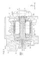
FIG. 1 is a cross-sectional view of a centrifugal compressor which incorporates a dynamic foil gas bearing according to an embodiment of the present invention; -
FIG. 2 is a cross-sectional view of main components of the centrifugal compressor; -
FIG. 3 is a cross-sectional view of the centrifugal compressor, taken along line III - III ofFIG. 2 ; -
FIG. 4 is a perspective view of a thrust air bearing of the centrifugal compressor; -
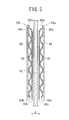
FIG. 5 is a cross-sectional view of the thrust air bearing, taken along line V - V ofFIG. 4 ; -
FIG. 6 is a fragmentary cross-sectional view of a journal air bearing according to a comparative example; -
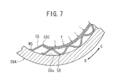
FIG. 7 is a fragmentary cross-sectional view showing the manner in which the journal air bearing according to the comparative example operates; and -
FIG. 8 is a fragmentary cross-sectional view of a foil fluid bearing disclosed in Japanese Laid-Open Patent Publication No.2001-295836 - As shown in
FIG. 1 , a centrifugal compressor (supercharger) 10 which incorporates a dynamic foil gas bearing according to an embodiment of the present invention includes acasing 12 in which arotatable shaft unit 14 is rotatably mounted. - As shown in
FIGS. 1 and2 , therotatable shaft unit 14 comprises arotor 20 having an annularpermanent magnet 16 and a hollow cylindricalprotective sleeve 18 disposed around thepermanent magnet 16 and housing therein thepermanent magnet 16, which may be shrink-fit in theprotective sleeve 18, for example, a pair ofbearing shafts rotor 20, and animpeller 26 mounted on the axial end of thebearing shaft 22 that is remote from therotor 20. - The
impeller 26 serves as part of acentrifugal compression unit 28 and has an end face held against a large-diameter end 30a of atension shaft 30. Thetension shaft 30 which extends axially through theimpeller 26 supports thereon thebearing shaft 22, therotor 20, and thebearing shaft 24 which are arranged successively in the order named from theimpeller 26. Thebearing shaft 22, therotor 20, and thebearing shaft 24 are integrally held together on thetension shaft 30 by a fasteningmember 32 that is threaded over the end of thetension shaft 30 which is remote from the large-diameter end 30a thereof. - The
fastening member 32 supports thereon acanceler mechanism 34 for reducing thrust force that is generated along the direction indicated by the arrow A1 when therotatable shaft unit 14 rotates about its own axis. As shown inFIG. 1 , thecanceler mechanism 34 includes acanceler disk 38 which is slidable in apressurization chamber 36 along the directions indicated by the arrow A. When theimpeller 26 rotates about its own axis, air is generated, and the generated air flows into thepressurization chamber 36 through apassageway 40. - The
casing 12 houses therein anannular stator 42 fixedly disposed around therotor 20. Thestator 42 and therotor 20 jointly make up amotor 46. - The
protective sleeve 18, which is part of therotor 20 and is required to be of high rigidity, is made of nickel-based superalloy, e.g., Inconel (tradename of Special Metals Corporation). A plurality ofcoolant water channels 48 extend around thestator 42. - As shown in
FIG. 2 , theprotective sleeve 18 has hollowcylindrical protrusions bearing shafts protrusions respective end faces permanent magnet 16. - The
bearing shaft 22 includes a hollow cylindrical member 22a which is open at an axial end thereof and abottom 22b which is disposed at an opposite axial end thereof and projects radially inwardly to thetension shaft 30. Similarly, thebearing shaft 24 includes a hollowcylindrical member 24a which is open at an axial end thereof and abottom 24b which is disposed at an opposite axial end thereof and projects radially inwardly to thetension shaft 30. - The
bottom 22b of thebearing shaft 22 is held in contact with the hollowcylindrical protrusion 18a of theprotective sleeve 18, and thebottom 24b of thebearing shaft 24 is held in contact with the hollowcylindrical protrusion 18b of theprotective sleeve 18. Thebottoms permanent magnet 16 are spaced from each other by respective distances S1, S2. - A foil gas bearing (dynamic foil gas bearing) 50 which holds the
bearing shafts bearing shafts journal air bearings bearing shafts bearing shaft 22 in its axial position. - The
bearing shafts journal air bearings bearing shafts protective sleeve 18, for example. When thebearing shafts journal air bearings bearing shafts bearing shafts journal air bearings - The
journal air bearings shafts FIG. 3 ) disposed respectively on innercircumferential surfaces bearing cases shafts cases - As shown in
FIG. 3 , thefoil group 57 in thebearing case 56A includes a corrugated-sheet-like bump foil 58, a flat-sheet-likemiddle foil 59, and a flat-sheet-liketop foil 60 which are arranged successively toward the central axis of thebearing case 56A. Each of the corrugated-sheet-like bump foil 58, the flat-sheet-likemiddle foil 59, and the flat-sheet-liketop foil 60 is in the form of an elastic metal member. Thebump foil 58 comprises a single foil or a plurality of foils and has anend 58a fixed by welding or the like to the innercircumferential surface 56a of thebearing case 56A and an opposite end as a free end. - The
middle foil 59 includes a first fixedsurface 59a fixed by welding or the like to the innercircumferential surface 56a of thebearing case 56A, and a first rotatableshaft holding surface 59c extending along the direction in which the bearingshaft 22 rotates, i.e., the direction indicated by the arrow C. The first rotatableshaft holding surface 59c has an end joined to the first fixedsurface 59a by a first linkage surface 59b and an opposite end as a free end. The first rotatableshaft holding surface 59c serves to restrain the bearingshaft 22 circumferentially. - The
top foil 60 includes a second fixedsurface 60a fixed by welding or the like to the innercircumferential surface 56a of thebearing case 56A, and a second rotatableshaft holding surface 60c extending along the direction (the direction indicated by the arrow D) which is opposite to the direction in which the bearingshaft 22 rotates, i.e., the direction indicated by the arrow C. The second rotatableshaft holding surface 60c has an end joined to the second fixedsurface 60a by asecond linkage surface 60b and an opposite end as a free end. The second rotatableshaft holding surface 60c serves to restrain the bearingshaft 22 circumferentially. The second fixedsurface 60a is disposed in a position adjacent to the first fixedsurface 59a. - The first linkage surface 59b is provided by a bent straight portion of the
middle foil 59. Thesecond linkage surface 60b is provided by a curved portion of thetop foil 60 which is convex toward the central axis of thebearing case 56A. The free end of thetop foil 60 extends toward the first fixedsurface 59a side (i.e., along the direction indicated by the arrow D) in covering relation to the first linkage surface 59b. Thebearing case 56B and thefoil group 57 disposed therein are of the same structure as thebearing case 56A and thefoil group 57 disposed therein. - As shown in
FIGS. 1 and2 , the bearingshaft 22 has a large-diameter flange 62 projecting radially outwardly from the outer circumferential surface thereof. The large-diameter flange 62 is sandwiched betweenring members diameter flange 62 and thering members thrust air bearing 54. - As shown in
FIG. 4 , each of thering members diameter flange 62. The bump foils 66 and the top foils 68 are superposed and arrayed in an annular pattern along an inner circumferential edge of each of thering members - As shown in
FIG. 5 , each of the bump foils 66 has anend 66a welded to one of thering members opposite end 66b as a free end. Each of the top foils 68 has anend 68a welded to one of thering members opposite end 68b as a free end. - As shown in
FIG. 2 , theimpeller 26 has anaxial end 26a which is remote from the large-diameter end 30a of thetension shaft 30 and coaxially fitted in the hollow cylindrical member 22a of the bearingshaft 22 by a spigot-and-socket joint. Thebottoms shafts cylindrical protrusions protective sleeve 18 by a spigot-and-socket joint. - As shown in
FIG. 1 , thecasing 12 has acoolant channel 70 defined between theprotective sleeve 18 and thestator 42 of themotor 46. The inlet of thecoolant channel 70 and thepassageway 40 of thecanceler mechanism 34 are connected to acompressor outlet 72 of thecentrifugal compression unit 28. When theimpeller 26 rotates about its own axis, it compresses air and delivers the compressed air from thecompressor outlet 72 into the inlet of thecoolant channel 70 and thepassageway 40 of thecanceler mechanism 34. - Operation of the
centrifugal compressor 10 will be described below. - When the
stator 42 of themotor 46 is energized, thepermanent magnet 16 and theprotective sleeve 18 of therotor 20 rotate in unison with thetension shaft 30. Theimpeller 26 which is supported on thetension shaft 30 rotates at a relatively high speed, and then draws air from the atmosphere into thecentrifugal compression unit 28. - The air that is drawn by the
impeller 26 is compressed and fed by thecentrifugal compression unit 28 to the oxygen-containing gas supply system of a fuel cell (not shown), for example. The fuel cell is supplied with a fuel gas, i.e., a hydrogen gas, from a fuel gas supply system (not shown). Therefore, the fuel cell generates electric energy based on a reaction between the air that is supplied to the cathode of the fuel cell and the hydrogen that is supplied to the anode of the fuel cell. - Part of the air that is drawn into the
centrifugal compression unit 28 is compressed thereby and supplied from thecompressor outlet 72 to thecoolant channel 70 in thecasing 12. The air cools themotor 46 while flowing through thecoolant channel 70, and is then discharged out of thecentrifugal compressor 10. - Part of the air compressed by the
centrifugal compression unit 28 is supplied from thecompressor outlet 72 through thepassageway 40 of thecanceler mechanism 34 to thepressurization chamber 36. When the air flows into thepressurization chamber 36, it applies a pressing force to thecanceler disk 38 in thepressurization chamber 36 in a direction away from theimpeller 26, i.e., in the direction indicated by the arrow A2. Therefore, the thrust force applied in the direction indicated by the arrow A1 is reduced by thecanceler mechanism 34 upon rotation of theimpeller 26. - According to the present embodiment, as shown in
FIG. 3 , each of thefoil groups 57 includes the corrugated-sheet-like bump foil 58, the flat-sheet-likemiddle foil 59, and the flat-sheet-liketop foil 60 which are arranged successively toward the central axis of thebearing case 56A. - The
second linkage surface 60b of thetop foil 60 which is joined to the second fixedsurface 60a fixed to the innercircumferential surface 56a of thebearing case 56A and is also joined to the second rotatableshaft holding surface 60c, is provided by a curved portion of thetop foil 60 which is convex toward the central axis of thebearing case 56A. Therefore, when thebump foil 58 is elastically deformed, thesecond linkage surface 60b of thetop foil 60 is prevented from being bent into contact with the outer circumferential surface of the bearingshaft 22. Consequently, with a simple structure, thetop foil 60 can be prevented from unduly wearing, as much as possible. - Specifically,
FIG. 6 shows a journal air bearing according to a comparative example which includes a top foil TF having a angularly bent surface CS that is joined to a fixed surface WS fixed to an innercircumferential surface 56a. When an air pressure f is applied to the top foil TF by air that is drawn upon rotation of the rotational shaft, the top foil TF tends to be elastically deformed about an edgy corner CSC of the angularly bent surface CS, as shown inFIG. 7 . Therefore, the edgy corner CSC projects radially inwardly into contact with the rotational shaft, thereby unduly wearing the rotational shaft. - According to the present embodiment, however, the
second linkage surface 60b of thetop foil 60 is provided by a curved portion of thetop foil 60 which is convex toward the central axis of thebearing case 56A. When an air pressure is applied to thetop foil 60 upon rotation of the bearingshaft 22, thetop foil 60 is liable to be elastically deformed about a boundary 60ab (seeFIG. 3 ) between the second fixedsurface 60a and thesecond linkage surface 60b. Therefore, thetop foil 60 is prevented from projecting radially inwardly and hence from unduly wearing, as much as possible. - In addition, the first linkage surface 59b of the
middle foil 59 which is joined to the first fixedsurface 59a fixed to the innercircumferential surface 56a of thebearing case 56A and is also joined to the first rotatableshaft holding surface 59c, is provided by a bent straight portion of themiddle foil 59. Accordingly, the first linkage surface 59b is effective to prevent the fixed portion from being reduced in rigidity, so that abnormal vibration is not caused upon high-speed rotation of the bearingshaft 22, and hence high-speed stability thereof can be maintained suitably. - Moreover, the free end of the
top foil 60 extends in the direction indicated by the arrow D in covering relation to the first linkage surface 59b of themiddle foil 59. Consequently, the first linkage surface 59b of themiddle foil 59 is prevented from being brought into sliding contact with the outer circumferential surface of the bearingshaft 22, and hence is reliably prevented from unduly wearing. - A dynamic foil gas bearing (50) includes a foil group (57) comprising a corrugated-sheet-like bump foil (58), a flat-sheet-like middle foil (59), and a flat-sheet-like top foil (60) which are arranged successively toward the center axis of a bearing case (56A). The top foil (60) includes a second linkage surface (60b) joined to a second fixed surface (60a) fixed to an inner circumferential surface (56a) of the bearing case (56A) and also joined to a second rotatable shaft holding surface (60c). The second linkage surface (60b) is provided by a curved portion of the top foil (60) which is convex toward the center axis of the bearing case (56A). The middle foil (59) includes a first linkage surface (59b) joined to a first fixed surface (59a) fixed to the inner circumferential surface (56a) of the bearing case (56A) and also joined to a first rotatable shaft holding surface (59c). The first linkage surface (59b) is provided by a bent straight portion of the middle foil (59).
Claims (3)
- A dynamic foil gas bearing (50) comprising:a hollow cylindrical member (56A) with a rotatable shaft (22) inserted therein; anda foil group (57) mounted on an inner circumferential surface (56a) of the hollow cylindrical member (56A), the dynamic foil gas bearing (50) supporting the rotatable shaft (22) in a journal direction;wherein the foil group (57) comprises a sheet-like bump foil (58), a sheet-like middle foil (59), and a sheet-like top foil (60) which are arranged successively toward the central axis of the hollow cylindrical member (56A);the middle foil (59) including:a first fixed surface (59a) fixed to an inner circumferential surface of the hollow cylindrical member (56A); anda first rotatable shaft holding surface (59c) extending along a direction in which the rotatable shaft (22) rotates, the first rotatable shaft holding surface (59c) having an end joined to the first fixed surface (59a) by a first linkage surface (59b) and an opposite end as a free end, the first rotatable shaft holding surface (59c) serving to restrain the rotatable shaft (22) circumferentially;the top foil (60) including:a second fixed surface (60a) fixed to the inner circumferential surface of the hollow cylindrical member (56A); anda second rotatable shaft holding surface (60c) extending along a direction opposite to the direction in which the rotatable shaft (22) rotates, the second rotatable shaft holding surface (60c) having an end joined to the second fixed surface (60a) by a second linkage surface (60b) and an opposite end as a free end, the rotatable shaft holding surface (60c) serving to restrain the rotatable shaft (22) circumferentially;wherein the first linkage surface (59b) is provided by a bent straight portion of the middle foil (59), and the second linkage surface (60b) is provided by a curved portion of the top foil (60), the curved portion being convex toward the central axis of the hollow cylindrical member (56A).
- The dynamic foil gas bearing (50) according to claim 1, wherein the free end of the top foil (60) extends toward the first fixed surface (59a) side in covering relation to the first linkage surface (59b) of the middle foil (59).
- The dynamic foil gas bearing (50) according to claim 1, wherein the rotatable shaft (22) serves as part of a rotatable shaft unit (14) of a centrifugal compressor (10), the centrifugal compressor (10) including an impeller (26) coupled to the rotatable shaft unit (14).
Applications Claiming Priority (1)
| Application Number | Priority Date | Filing Date | Title |
|---|---|---|---|
| JP2010079462A JP4961485B2 (en) | 2010-03-30 | 2010-03-30 | Dynamic pressure type foil type gas bearing |
Publications (3)
| Publication Number | Publication Date |
|---|---|
| EP2375089A2 true EP2375089A2 (en) | 2011-10-12 |
| EP2375089A3 EP2375089A3 (en) | 2012-05-02 |
| EP2375089B1 EP2375089B1 (en) | 2013-05-29 |
Family
ID=43923520
Family Applications (1)
| Application Number | Title | Priority Date | Filing Date |
|---|---|---|---|
| EP11160166.2A Not-in-force EP2375089B1 (en) | 2010-03-30 | 2011-03-29 | Dynamic foil gas bearing |
Country Status (3)
| Country | Link |
|---|---|
| US (1) | US8475048B2 (en) |
| EP (1) | EP2375089B1 (en) |
| JP (1) | JP4961485B2 (en) |
Cited By (3)
| Publication number | Priority date | Publication date | Assignee | Title |
|---|---|---|---|---|
| US9732790B2 (en) | 2013-12-05 | 2017-08-15 | Liebherr-Aerospace Toulouse Sas | Aerodynamic foil bearing |
| WO2019137024A1 (en) * | 2018-01-12 | 2019-07-18 | 至玥腾风科技投资集团有限公司 | Thrust bearing, rotor system and control method for thrust bearing |
| WO2020064799A1 (en) | 2018-09-26 | 2020-04-02 | Ebm-Papst Mulfingen Gmbh & Co. Kg | Film gas bearing device for mounting a rotor and method and use |
Families Citing this family (25)
| Publication number | Priority date | Publication date | Assignee | Title |
|---|---|---|---|---|
| KR100964883B1 (en) * | 2009-10-07 | 2010-06-23 | 주식회사 뉴로스 | Thrust foil air bearing |
| KR101981684B1 (en) * | 2011-08-24 | 2019-05-23 | 보르그워너 인코퍼레이티드 | Bearing arrangement |
| JP6113573B2 (en) * | 2013-05-08 | 2017-04-12 | Nok株式会社 | Center bearing support |
| CN103438091B (en) * | 2013-08-02 | 2015-12-02 | 湖南大学 | There is the air hydrodynamic bearing of metal-rubber and compliant foil composite support structure |
| CN104454992B (en) * | 2014-09-30 | 2017-02-15 | 湖南大学 | Elastic radial air bearing |
| FR3034460B1 (en) | 2015-04-01 | 2019-07-19 | Liebherr-Aerospace Toulouse Sas | ROTOR AND ROTOR TURBOMACHINE ASSEMBLY AT VERY HIGH SPEEDS INCLUDING SUCH A ROTOR ASSEMBLY |
| KR102601001B1 (en) * | 2015-06-27 | 2023-11-13 | 보르그워너 인코퍼레이티드 | Air bearing arrangement for lectrically driven compressors |
| US10385915B2 (en) | 2016-08-16 | 2019-08-20 | Hamilton Sundstrand Corporation | High load capacity hybrid foil bearing |
| FR3055678B1 (en) * | 2016-09-02 | 2020-09-18 | Danfoss Silicon Power Gmbh | AXIAL BEARING ARRANGEMENT FOR A CENTRIFUGAL COMPRESSOR DRIVE SHAFT |
| FR3055677B1 (en) * | 2016-09-02 | 2020-05-29 | Danfoss A/S | MODULAR TURBOCHARGER SHAFT |
| CN109312661B (en) * | 2016-09-02 | 2020-12-25 | 株式会社Ihi | Impeller for supercharger |
| CN106678058A (en) * | 2017-02-22 | 2017-05-17 | 上海优耐特斯压缩机有限公司 | Superspeed rotor structure of high-speed motor direct-driven turbine machine |
| US11306771B2 (en) | 2017-03-15 | 2022-04-19 | Ihi Corporation | Radial foil bearing |
| EP3597945B1 (en) | 2017-03-15 | 2022-05-18 | IHI Corporation | Radial foil bearing |
| FR3074622B1 (en) * | 2017-12-04 | 2021-07-30 | Ifp Energies Now | DEVICE FOR COMPRESSION OF A FLUID DRIVEN BY AN ELECTRIC MACHINE WITH A ROTOR SHAFT HAVING AN AMAGNETIC FRET |
| DE102018212490A1 (en) * | 2018-07-26 | 2020-01-30 | Ebm-Papst Mulfingen Gmbh & Co. Kg | Foil gas storage device for storing a rotor and method and use |
| US11391291B2 (en) | 2019-02-07 | 2022-07-19 | Emerson Climate Technologies, Inc. | Foil bearing assembly |
| CN110439847B (en) * | 2019-08-30 | 2022-01-11 | 广州市昊志机电股份有限公司 | Centrifugal compressor shafting structure and centrifugal compressor |
| CN113107965A (en) * | 2020-01-09 | 2021-07-13 | 珠海格力电器股份有限公司 | Axial gas bearing and centrifugal compressor |
| CN113107893A (en) * | 2020-01-09 | 2021-07-13 | 珠海格力电器股份有限公司 | Axial air suspension bearing, compressor and air conditioner |
| DE102021108887B3 (en) | 2021-04-09 | 2022-09-15 | Schaeffler Technologies AG & Co. KG | Radial foil bearing with foil packs welded on the face side |
| CN113217530B (en) * | 2021-04-29 | 2025-01-03 | 姚漠寒 | A thrust foil air bearing |
| CN113266636A (en) * | 2021-05-18 | 2021-08-17 | 四川省机械研究设计院(集团)有限公司 | Self-adaptive balanced air film dynamic pressure air bearing structure |
| CN116066470B (en) * | 2023-02-13 | 2025-08-15 | 中船重工(重庆)西南装备研究院有限公司 | Multi-tile lap joint type radial foil gas bearing and assembly method thereof |
| DE102024102696A1 (en) * | 2024-01-31 | 2025-07-31 | Ebm-Papst Mulfingen Gmbh & Co. Kg | Aerodynamic bearing for axial and radial support of a shaft and turbo compressor with such a bearing |
Citations (1)
| Publication number | Priority date | Publication date | Assignee | Title |
|---|---|---|---|---|
| JP2001295836A (en) | 2000-04-10 | 2001-10-26 | Honda Motor Co Ltd | Foil type fluid bearing |
Family Cites Families (13)
| Publication number | Priority date | Publication date | Assignee | Title |
|---|---|---|---|---|
| JPS5045148A (en) * | 1973-08-27 | 1975-04-23 | ||
| JPS5058453A (en) * | 1973-09-25 | 1975-05-21 | ||
| US4133585A (en) * | 1977-08-04 | 1979-01-09 | United Technologies Corporation | Resilient foil journal bearing |
| US4300806A (en) * | 1980-04-03 | 1981-11-17 | Mechanical Technology Incorporated | Multi-stage support element for compliant hydrodynamic bearings |
| US4415280A (en) * | 1981-11-23 | 1983-11-15 | United Technologies Corporation | Hydrodynamic fluid film bearing |
| JP4031614B2 (en) * | 1999-12-03 | 2008-01-09 | 三菱重工業株式会社 | Foil gas bearing |
| JP4502548B2 (en) * | 2001-06-12 | 2010-07-14 | 本田技研工業株式会社 | Foil type hydrodynamic bearing |
| JP4322497B2 (en) * | 2002-12-05 | 2009-09-02 | 株式会社東芝 | Split type gas lubricated foil bearing |
| US7070330B2 (en) * | 2004-02-19 | 2006-07-04 | R & D Dynamics Corporation | Hydrodynamic fluid film bearing having a key-less foil |
| US7553086B2 (en) * | 2004-07-20 | 2009-06-30 | Honeywell International Inc. | Hydrodynamic journal bearing |
| JP2006177542A (en) * | 2004-12-21 | 2006-07-06 | Shigeto Matsuo | Spring foil bearing |
| US7648280B2 (en) * | 2007-04-12 | 2010-01-19 | Hamilton Sundstrand Corporation | Weight reduction for journal air bearing |
| US7648279B2 (en) * | 2007-04-12 | 2010-01-19 | Hamilton Sundstrand Corporation | Journal air bearing |
-
2010
- 2010-03-30 JP JP2010079462A patent/JP4961485B2/en not_active Expired - Fee Related
-
2011
- 2011-03-29 EP EP11160166.2A patent/EP2375089B1/en not_active Not-in-force
- 2011-03-30 US US13/076,036 patent/US8475048B2/en not_active Expired - Fee Related
Patent Citations (1)
| Publication number | Priority date | Publication date | Assignee | Title |
|---|---|---|---|---|
| JP2001295836A (en) | 2000-04-10 | 2001-10-26 | Honda Motor Co Ltd | Foil type fluid bearing |
Cited By (3)
| Publication number | Priority date | Publication date | Assignee | Title |
|---|---|---|---|---|
| US9732790B2 (en) | 2013-12-05 | 2017-08-15 | Liebherr-Aerospace Toulouse Sas | Aerodynamic foil bearing |
| WO2019137024A1 (en) * | 2018-01-12 | 2019-07-18 | 至玥腾风科技投资集团有限公司 | Thrust bearing, rotor system and control method for thrust bearing |
| WO2020064799A1 (en) | 2018-09-26 | 2020-04-02 | Ebm-Papst Mulfingen Gmbh & Co. Kg | Film gas bearing device for mounting a rotor and method and use |
Also Published As
| Publication number | Publication date |
|---|---|
| US8475048B2 (en) | 2013-07-02 |
| JP4961485B2 (en) | 2012-06-27 |
| US20110243485A1 (en) | 2011-10-06 |
| JP2011208785A (en) | 2011-10-20 |
| EP2375089B1 (en) | 2013-05-29 |
| EP2375089A3 (en) | 2012-05-02 |
Similar Documents
| Publication | Publication Date | Title |
|---|---|---|
| EP2375089B1 (en) | Dynamic foil gas bearing | |
| EP2375082A2 (en) | Motor-driven centrifugal compressor | |
| US8821136B2 (en) | Supercharger | |
| EP2910789B1 (en) | Sealing arrangement for fuel cell compressor | |
| EP2924294B1 (en) | Electric motor-driven compressor having a heat shield forming a wall of a diffuser | |
| JP5174241B2 (en) | Shaft seal and rotating machine equipped with the same | |
| CN103842695A (en) | Shaft sealing device and rotating machine comprising same | |
| CN102132052A (en) | Thrust foil bearing | |
| JP2011202588A (en) | Centrifugal compressor | |
| JP2011202589A (en) | Centrifugal compressor | |
| JP5174074B2 (en) | Electric centrifugal compressor | |
| JP5497489B2 (en) | Centrifugal compressor | |
| US10415644B2 (en) | Rotary machine | |
| EP3173599B1 (en) | Variable nozzle mechanism and variable displacement turbocharger | |
| JP6559717B2 (en) | mechanical seal | |
| JP2011169413A (en) | Dynamic pressure gas journal bearing | |
| CN113840984A (en) | Vacuum pump and vacuum pump components | |
| JP5094897B2 (en) | Electric centrifugal compressor | |
| JP5174069B2 (en) | Centrifugal compressor | |
| JP2008151207A (en) | Compressor | |
| JP4706523B2 (en) | Compressor for fuel cell | |
| JP2011169190A (en) | Centrifugal compressor | |
| JP5208055B2 (en) | Rotor structure | |
| WO2019160013A1 (en) | Seal segment and rotating machine |
Legal Events
| Date | Code | Title | Description |
|---|---|---|---|
| PUAI | Public reference made under article 153(3) epc to a published international application that has entered the european phase |
Free format text: ORIGINAL CODE: 0009012 |
|
| 17P | Request for examination filed |
Effective date: 20110329 |
|
| AK | Designated contracting states |
Kind code of ref document: A2 Designated state(s): AL AT BE BG CH CY CZ DE DK EE ES FI FR GB GR HR HU IE IS IT LI LT LU LV MC MK MT NL NO PL PT RO RS SE SI SK SM TR |
|
| AX | Request for extension of the european patent |
Extension state: BA ME |
|
| PUAL | Search report despatched |
Free format text: ORIGINAL CODE: 0009013 |
|
| AK | Designated contracting states |
Kind code of ref document: A3 Designated state(s): AL AT BE BG CH CY CZ DE DK EE ES FI FR GB GR HR HU IE IS IT LI LT LU LV MC MK MT NL NO PL PT RO RS SE SI SK SM TR |
|
| AX | Request for extension of the european patent |
Extension state: BA ME |
|
| RIC1 | Information provided on ipc code assigned before grant |
Ipc: F16C 17/12 20060101AFI20120326BHEP Ipc: F16C 27/02 20060101ALI20120326BHEP |
|
| GRAP | Despatch of communication of intention to grant a patent |
Free format text: ORIGINAL CODE: EPIDOSNIGR1 |
|
| RIC1 | Information provided on ipc code assigned before grant |
Ipc: F16C 17/12 20060101AFI20121203BHEP Ipc: F16C 27/02 20060101ALI20121203BHEP |
|
| GRAS | Grant fee paid |
Free format text: ORIGINAL CODE: EPIDOSNIGR3 |
|
| GRAA | (expected) grant |
Free format text: ORIGINAL CODE: 0009210 |
|
| AK | Designated contracting states |
Kind code of ref document: B1 Designated state(s): AL AT BE BG CH CY CZ DE DK EE ES FI FR GB GR HR HU IE IS IT LI LT LU LV MC MK MT NL NO PL PT RO RS SE SI SK SM TR |
|
| REG | Reference to a national code |
Ref country code: GB Ref legal event code: FG4D |
|
| REG | Reference to a national code |
Ref country code: CH Ref legal event code: EP |
|
| REG | Reference to a national code |
Ref country code: AT Ref legal event code: REF Ref document number: 614586 Country of ref document: AT Kind code of ref document: T Effective date: 20130615 |
|
| REG | Reference to a national code |
Ref country code: IE Ref legal event code: FG4D |
|
| REG | Reference to a national code |
Ref country code: DE Ref legal event code: R096 Ref document number: 602011001777 Country of ref document: DE Effective date: 20130725 |
|
| REG | Reference to a national code |
Ref country code: AT Ref legal event code: MK05 Ref document number: 614586 Country of ref document: AT Kind code of ref document: T Effective date: 20130529 |
|
| REG | Reference to a national code |
Ref country code: LT Ref legal event code: MG4D |
|
| PG25 | Lapsed in a contracting state [announced via postgrant information from national office to epo] |
Ref country code: SE Free format text: LAPSE BECAUSE OF FAILURE TO SUBMIT A TRANSLATION OF THE DESCRIPTION OR TO PAY THE FEE WITHIN THE PRESCRIBED TIME-LIMIT Effective date: 20130529 Ref country code: IS Free format text: LAPSE BECAUSE OF FAILURE TO SUBMIT A TRANSLATION OF THE DESCRIPTION OR TO PAY THE FEE WITHIN THE PRESCRIBED TIME-LIMIT Effective date: 20130929 Ref country code: FI Free format text: LAPSE BECAUSE OF FAILURE TO SUBMIT A TRANSLATION OF THE DESCRIPTION OR TO PAY THE FEE WITHIN THE PRESCRIBED TIME-LIMIT Effective date: 20130529 Ref country code: NO Free format text: LAPSE BECAUSE OF FAILURE TO SUBMIT A TRANSLATION OF THE DESCRIPTION OR TO PAY THE FEE WITHIN THE PRESCRIBED TIME-LIMIT Effective date: 20130829 Ref country code: GR Free format text: LAPSE BECAUSE OF FAILURE TO SUBMIT A TRANSLATION OF THE DESCRIPTION OR TO PAY THE FEE WITHIN THE PRESCRIBED TIME-LIMIT Effective date: 20130830 Ref country code: PT Free format text: LAPSE BECAUSE OF FAILURE TO SUBMIT A TRANSLATION OF THE DESCRIPTION OR TO PAY THE FEE WITHIN THE PRESCRIBED TIME-LIMIT Effective date: 20130930 Ref country code: LT Free format text: LAPSE BECAUSE OF FAILURE TO SUBMIT A TRANSLATION OF THE DESCRIPTION OR TO PAY THE FEE WITHIN THE PRESCRIBED TIME-LIMIT Effective date: 20130529 Ref country code: ES Free format text: LAPSE BECAUSE OF FAILURE TO SUBMIT A TRANSLATION OF THE DESCRIPTION OR TO PAY THE FEE WITHIN THE PRESCRIBED TIME-LIMIT Effective date: 20130909 Ref country code: AT Free format text: LAPSE BECAUSE OF FAILURE TO SUBMIT A TRANSLATION OF THE DESCRIPTION OR TO PAY THE FEE WITHIN THE PRESCRIBED TIME-LIMIT Effective date: 20130529 Ref country code: SI Free format text: LAPSE BECAUSE OF FAILURE TO SUBMIT A TRANSLATION OF THE DESCRIPTION OR TO PAY THE FEE WITHIN THE PRESCRIBED TIME-LIMIT Effective date: 20130529 |
|
| REG | Reference to a national code |
Ref country code: NL Ref legal event code: VDEP Effective date: 20130529 |
|
| PG25 | Lapsed in a contracting state [announced via postgrant information from national office to epo] |
Ref country code: BG Free format text: LAPSE BECAUSE OF FAILURE TO SUBMIT A TRANSLATION OF THE DESCRIPTION OR TO PAY THE FEE WITHIN THE PRESCRIBED TIME-LIMIT Effective date: 20130829 Ref country code: HR Free format text: LAPSE BECAUSE OF FAILURE TO SUBMIT A TRANSLATION OF THE DESCRIPTION OR TO PAY THE FEE WITHIN THE PRESCRIBED TIME-LIMIT Effective date: 20130529 Ref country code: RS Free format text: LAPSE BECAUSE OF FAILURE TO SUBMIT A TRANSLATION OF THE DESCRIPTION OR TO PAY THE FEE WITHIN THE PRESCRIBED TIME-LIMIT Effective date: 20130529 Ref country code: PL Free format text: LAPSE BECAUSE OF FAILURE TO SUBMIT A TRANSLATION OF THE DESCRIPTION OR TO PAY THE FEE WITHIN THE PRESCRIBED TIME-LIMIT Effective date: 20130529 |
|
| PG25 | Lapsed in a contracting state [announced via postgrant information from national office to epo] |
Ref country code: LV Free format text: LAPSE BECAUSE OF FAILURE TO SUBMIT A TRANSLATION OF THE DESCRIPTION OR TO PAY THE FEE WITHIN THE PRESCRIBED TIME-LIMIT Effective date: 20130529 |
|
| PG25 | Lapsed in a contracting state [announced via postgrant information from national office to epo] |
Ref country code: SK Free format text: LAPSE BECAUSE OF FAILURE TO SUBMIT A TRANSLATION OF THE DESCRIPTION OR TO PAY THE FEE WITHIN THE PRESCRIBED TIME-LIMIT Effective date: 20130529 Ref country code: BE Free format text: LAPSE BECAUSE OF FAILURE TO SUBMIT A TRANSLATION OF THE DESCRIPTION OR TO PAY THE FEE WITHIN THE PRESCRIBED TIME-LIMIT Effective date: 20130529 Ref country code: CZ Free format text: LAPSE BECAUSE OF FAILURE TO SUBMIT A TRANSLATION OF THE DESCRIPTION OR TO PAY THE FEE WITHIN THE PRESCRIBED TIME-LIMIT Effective date: 20130529 Ref country code: DK Free format text: LAPSE BECAUSE OF FAILURE TO SUBMIT A TRANSLATION OF THE DESCRIPTION OR TO PAY THE FEE WITHIN THE PRESCRIBED TIME-LIMIT Effective date: 20130529 Ref country code: EE Free format text: LAPSE BECAUSE OF FAILURE TO SUBMIT A TRANSLATION OF THE DESCRIPTION OR TO PAY THE FEE WITHIN THE PRESCRIBED TIME-LIMIT Effective date: 20130529 |
|
| PG25 | Lapsed in a contracting state [announced via postgrant information from national office to epo] |
Ref country code: RO Free format text: LAPSE BECAUSE OF FAILURE TO SUBMIT A TRANSLATION OF THE DESCRIPTION OR TO PAY THE FEE WITHIN THE PRESCRIBED TIME-LIMIT Effective date: 20130529 Ref country code: NL Free format text: LAPSE BECAUSE OF FAILURE TO SUBMIT A TRANSLATION OF THE DESCRIPTION OR TO PAY THE FEE WITHIN THE PRESCRIBED TIME-LIMIT Effective date: 20130529 Ref country code: IT Free format text: LAPSE BECAUSE OF FAILURE TO SUBMIT A TRANSLATION OF THE DESCRIPTION OR TO PAY THE FEE WITHIN THE PRESCRIBED TIME-LIMIT Effective date: 20130529 |
|
| PLBE | No opposition filed within time limit |
Free format text: ORIGINAL CODE: 0009261 |
|
| STAA | Information on the status of an ep patent application or granted ep patent |
Free format text: STATUS: NO OPPOSITION FILED WITHIN TIME LIMIT |
|
| 26N | No opposition filed |
Effective date: 20140303 |
|
| REG | Reference to a national code |
Ref country code: DE Ref legal event code: R097 Ref document number: 602011001777 Country of ref document: DE Effective date: 20140303 |
|
| PGFP | Annual fee paid to national office [announced via postgrant information from national office to epo] |
Ref country code: DE Payment date: 20140228 Year of fee payment: 4 |
|
| PG25 | Lapsed in a contracting state [announced via postgrant information from national office to epo] |
Ref country code: LU Free format text: LAPSE BECAUSE OF FAILURE TO SUBMIT A TRANSLATION OF THE DESCRIPTION OR TO PAY THE FEE WITHIN THE PRESCRIBED TIME-LIMIT Effective date: 20140329 |
|
| REG | Reference to a national code |
Ref country code: CH Ref legal event code: PL |
|
| PGFP | Annual fee paid to national office [announced via postgrant information from national office to epo] |
Ref country code: FR Payment date: 20140530 Year of fee payment: 4 |
|
| REG | Reference to a national code |
Ref country code: IE Ref legal event code: MM4A |
|
| PG25 | Lapsed in a contracting state [announced via postgrant information from national office to epo] |
Ref country code: IE Free format text: LAPSE BECAUSE OF NON-PAYMENT OF DUE FEES Effective date: 20140329 Ref country code: LI Free format text: LAPSE BECAUSE OF NON-PAYMENT OF DUE FEES Effective date: 20140331 Ref country code: CH Free format text: LAPSE BECAUSE OF NON-PAYMENT OF DUE FEES Effective date: 20140331 |
|
| REG | Reference to a national code |
Ref country code: DE Ref legal event code: R119 Ref document number: 602011001777 Country of ref document: DE |
|
| GBPC | Gb: european patent ceased through non-payment of renewal fee |
Effective date: 20150329 |
|
| REG | Reference to a national code |
Ref country code: FR Ref legal event code: ST Effective date: 20151130 |
|
| PG25 | Lapsed in a contracting state [announced via postgrant information from national office to epo] |
Ref country code: GB Free format text: LAPSE BECAUSE OF NON-PAYMENT OF DUE FEES Effective date: 20150329 Ref country code: DE Free format text: LAPSE BECAUSE OF NON-PAYMENT OF DUE FEES Effective date: 20151001 |
|
| PG25 | Lapsed in a contracting state [announced via postgrant information from national office to epo] |
Ref country code: MT Free format text: LAPSE BECAUSE OF FAILURE TO SUBMIT A TRANSLATION OF THE DESCRIPTION OR TO PAY THE FEE WITHIN THE PRESCRIBED TIME-LIMIT Effective date: 20130529 Ref country code: FR Free format text: LAPSE BECAUSE OF NON-PAYMENT OF DUE FEES Effective date: 20150331 |
|
| PG25 | Lapsed in a contracting state [announced via postgrant information from national office to epo] |
Ref country code: SM Free format text: LAPSE BECAUSE OF FAILURE TO SUBMIT A TRANSLATION OF THE DESCRIPTION OR TO PAY THE FEE WITHIN THE PRESCRIBED TIME-LIMIT Effective date: 20130529 |
|
| PG25 | Lapsed in a contracting state [announced via postgrant information from national office to epo] |
Ref country code: MC Free format text: LAPSE BECAUSE OF FAILURE TO SUBMIT A TRANSLATION OF THE DESCRIPTION OR TO PAY THE FEE WITHIN THE PRESCRIBED TIME-LIMIT Effective date: 20130529 |
|
| PG25 | Lapsed in a contracting state [announced via postgrant information from national office to epo] |
Ref country code: CY Free format text: LAPSE BECAUSE OF FAILURE TO SUBMIT A TRANSLATION OF THE DESCRIPTION OR TO PAY THE FEE WITHIN THE PRESCRIBED TIME-LIMIT Effective date: 20130529 |
|
| PG25 | Lapsed in a contracting state [announced via postgrant information from national office to epo] |
Ref country code: TR Free format text: LAPSE BECAUSE OF FAILURE TO SUBMIT A TRANSLATION OF THE DESCRIPTION OR TO PAY THE FEE WITHIN THE PRESCRIBED TIME-LIMIT Effective date: 20130529 Ref country code: HU Free format text: LAPSE BECAUSE OF FAILURE TO SUBMIT A TRANSLATION OF THE DESCRIPTION OR TO PAY THE FEE WITHIN THE PRESCRIBED TIME-LIMIT; INVALID AB INITIO Effective date: 20110329 |
|
| PG25 | Lapsed in a contracting state [announced via postgrant information from national office to epo] |
Ref country code: MK Free format text: LAPSE BECAUSE OF FAILURE TO SUBMIT A TRANSLATION OF THE DESCRIPTION OR TO PAY THE FEE WITHIN THE PRESCRIBED TIME-LIMIT Effective date: 20130529 |
|
| PG25 | Lapsed in a contracting state [announced via postgrant information from national office to epo] |
Ref country code: AL Free format text: LAPSE BECAUSE OF FAILURE TO SUBMIT A TRANSLATION OF THE DESCRIPTION OR TO PAY THE FEE WITHIN THE PRESCRIBED TIME-LIMIT Effective date: 20130529 |