EP2375066A1 - Canopy for a wind turbine nacelle - Google Patents
Canopy for a wind turbine nacelle Download PDFInfo
- Publication number
- EP2375066A1 EP2375066A1 EP10159129A EP10159129A EP2375066A1 EP 2375066 A1 EP2375066 A1 EP 2375066A1 EP 10159129 A EP10159129 A EP 10159129A EP 10159129 A EP10159129 A EP 10159129A EP 2375066 A1 EP2375066 A1 EP 2375066A1
- Authority
- EP
- European Patent Office
- Prior art keywords
- bars
- canopy
- aluminium
- plates
- covering plates
- Prior art date
- Legal status (The legal status is an assumption and is not a legal conclusion. Google has not performed a legal analysis and makes no representation as to the accuracy of the status listed.)
- Granted
Links
- 239000000463 material Substances 0.000 claims abstract description 19
- 239000002861 polymer material Substances 0.000 claims abstract description 9
- 229910052751 metal Inorganic materials 0.000 claims abstract description 8
- 239000002184 metal Substances 0.000 claims abstract description 8
- 239000006262 metallic foam Substances 0.000 claims abstract description 3
- 239000004411 aluminium Substances 0.000 claims description 45
- 229910052782 aluminium Inorganic materials 0.000 claims description 45
- XAGFODPZIPBFFR-UHFFFAOYSA-N aluminium Chemical compound [Al] XAGFODPZIPBFFR-UHFFFAOYSA-N 0.000 claims description 45
- 229910000831 Steel Inorganic materials 0.000 claims description 17
- 239000010959 steel Substances 0.000 claims description 17
- 229920000515 polycarbonate Polymers 0.000 claims description 12
- 239000004417 polycarbonate Substances 0.000 claims description 12
- 239000004952 Polyamide Substances 0.000 claims description 10
- ZZUFCTLCJUWOSV-UHFFFAOYSA-N furosemide Chemical compound C1=C(Cl)C(S(=O)(=O)N)=CC(C(O)=O)=C1NCC1=CC=CO1 ZZUFCTLCJUWOSV-UHFFFAOYSA-N 0.000 claims description 10
- 229920002647 polyamide Polymers 0.000 claims description 10
- 239000006260 foam Substances 0.000 claims description 9
- 238000005304 joining Methods 0.000 claims description 8
- 239000003292 glue Substances 0.000 claims description 5
- 238000000034 method Methods 0.000 description 29
- 238000001125 extrusion Methods 0.000 description 10
- 238000003466 welding Methods 0.000 description 8
- 238000005260 corrosion Methods 0.000 description 3
- 230000007797 corrosion Effects 0.000 description 3
- 238000004026 adhesive bonding Methods 0.000 description 2
- 230000007423 decrease Effects 0.000 description 2
- 238000004512 die casting Methods 0.000 description 2
- 238000007789 sealing Methods 0.000 description 2
- 238000005452 bending Methods 0.000 description 1
- 238000010276 construction Methods 0.000 description 1
- 238000011161 development Methods 0.000 description 1
- 230000018109 developmental process Effects 0.000 description 1
- 150000002739 metals Chemical class 0.000 description 1
- 238000002360 preparation method Methods 0.000 description 1
Images

Classifications
-
- F—MECHANICAL ENGINEERING; LIGHTING; HEATING; WEAPONS; BLASTING
- F03—MACHINES OR ENGINES FOR LIQUIDS; WIND, SPRING, OR WEIGHT MOTORS; PRODUCING MECHANICAL POWER OR A REACTIVE PROPULSIVE THRUST, NOT OTHERWISE PROVIDED FOR
- F03D—WIND MOTORS
- F03D80/00—Details, components or accessories not provided for in groups F03D1/00 - F03D17/00
-
- F—MECHANICAL ENGINEERING; LIGHTING; HEATING; WEAPONS; BLASTING
- F05—INDEXING SCHEMES RELATING TO ENGINES OR PUMPS IN VARIOUS SUBCLASSES OF CLASSES F01-F04
- F05B—INDEXING SCHEME RELATING TO WIND, SPRING, WEIGHT, INERTIA OR LIKE MOTORS, TO MACHINES OR ENGINES FOR LIQUIDS COVERED BY SUBCLASSES F03B, F03D AND F03G
- F05B2240/00—Components
- F05B2240/10—Stators
- F05B2240/14—Casings, housings, nacelles, gondels or the like, protecting or supporting assemblies there within
-
- Y—GENERAL TAGGING OF NEW TECHNOLOGICAL DEVELOPMENTS; GENERAL TAGGING OF CROSS-SECTIONAL TECHNOLOGIES SPANNING OVER SEVERAL SECTIONS OF THE IPC; TECHNICAL SUBJECTS COVERED BY FORMER USPC CROSS-REFERENCE ART COLLECTIONS [XRACs] AND DIGESTS
- Y02—TECHNOLOGIES OR APPLICATIONS FOR MITIGATION OR ADAPTATION AGAINST CLIMATE CHANGE
- Y02E—REDUCTION OF GREENHOUSE GAS [GHG] EMISSIONS, RELATED TO ENERGY GENERATION, TRANSMISSION OR DISTRIBUTION
- Y02E10/00—Energy generation through renewable energy sources
- Y02E10/70—Wind energy
- Y02E10/72—Wind turbines with rotation axis in wind direction
Definitions
- the present invention relates to a canopy for a wind turbine nacelle which comprises a frame made of bars and covering plates.
- a canopy for a nacelle of a wind turbine comprising a frame and covering elements held by the frame is disclosed in DE 10 2006 001 931 A1 .
- the frame and the covering plates are curved to increase stability against forces acting from the outside of an assembled canopy and made from sandwich structures without core. Whether the frame is self-supporting or not is not mentioned.
- the first objective is solved by a canopy for a wind turbine nacelle as claimed in claim 1 and the second objective is solved by a wind turbine nacelle as claimed in claim 13.
- the depending claims contain further developments of the invention.
- An inventive canopy for a wind turbine nacelle comprises a frame made of bares and covering plates.
- the bars are made of metal, for example steel or aluminium.
- the frame is self supporting.
- the covering plates of the inventive canopy can be made of a material that comprises a polymer material and/or that comprises a sandwich material comprising a metal foam.
- at least one of the covering plates is made of a material that comprises a structured polymer material which structuring provides for a higher stiffness than unstructured polymer material.
- the bars of the space frame can be connected by functional shapes, as nodes, which are made of aluminium pressure die casting.
- the functional shapes make form closure possible.
- the die cast nodes and the aluminium bars can be put into form closure and glued additionally.
- Steel bars of a space frame can be connected by different welding processes or by die casted nodes.
- the bars and/or nodes can be connected to each other by form closure, screw connections, glue connections or weld connections, etc.
- the bars being made of aluminium they may be formed by an extrusion process (extruded aluminium bars).
- the bars are made of steel they can be made by a hydro forming process (hydro formed steel bars).
- Extruded aluminium bars offer the advantage that higher durability of the bars can be expected. This comes from the fact that no welding process is needed to connect the bars to each other or to connect the covering plates to the bars. As a consequence, there are neither flanges for the welding connection nor room for the welding devices needed.
- the bar extrusion contact patterns of different designs can be created. For example, functionalities can be integrated into the bars, e.g. screw shapes, holes for bolts or harpoon beams. Harpoon beam shapes can be used to connect the aluminium bars with sealing devices of rubber or bushings. It is also possible to provide aluminium bars with different wall thicknesses within one and the same bar by using the extrusion process for forming the aluminium bars.
- the bars may be formed by a hydro forming process.
- the bars can be made of a hollow shape and a complex geometry by means of single process.
- the process goes fast and with a high process safety.
- the number of contact patterns and the number of single parts can be reduced on the one hand.
- a high shape quality can be reached next to a homogeneous durability by a cold-hardening process.
- a draw back, as compared to extruded aluminium bars is the great effort on bending as a preparation of the hydro forming process.
- hydro formed steel bars as well as extruded aluminium bars can be connected by nodes.
- the nodes may either be die casted or formed by functional shapes of the bars themselves.
- the nodes can be die casted.
- At least one covering plate of the canopy may be made of a material that comprises polyamide and/or polycarbonate and/or a sandwich material containing aluminium foam.
- at least one of the covering plates may consist of a polyamide material and/or at least one of the covering plates may consist of a polycarbonate material and/or at least one of the covering plates may consist of a sandwich material containing aluminium foam.
- covering plates made from polymer materials show no corrosion. If a higher stiffness is needed, the plates made of a sandwich material containing aluminium foam can be used.
- polycarbonate or polyamide plates with a structure shape can be used to increase stiffness.
- the bars of the space of frame and the covering plates can be glued together. Additionally or alternatively, in case of the bars being made of aluminium, the covering plates may be connected to the bars by form closure, e.g. by using harpoon beams. Hence, in both cases no welding process for connecting the covering plates to the space frame is needed. As a consequence, the assembly process of the canopy is easy to accomplish and safe to handle.
- Joining elements may be integrated into the covering plates and/or into the bars.
- the covering plates may comprise integrated applications like seals, in particular sprayed seals, lights, hatches, lockings, etc.
- a wind turbine nacelle with an inventive canopy is provided.
- the advantages of such a nacelle follow directly from the advantages discussed with respect to the inventive canopy.
- FIGS 1 to 3 show the space frame of the canopy 1 in a bottom view ( Figure 1 ), a side view ( Figure 2 ) and a top view ( Figure 3 ), respectively.
- Figures 1 to 3 show the bars 3 and nodes 5 making up the space frame.
- the bottom side of the space frame comprises a circular opening 7 for receiving a tower of a wind turbine. Moreover, the bottom side comprises a space frame segment 9 of larger dimensions than normal space frame segments 11.
- a normal space frame segment in the sense of the present invention is a space frame segment delimited by single space frame bars in each direction. Space frame segments of larger dimensions are formed by removing bars between neighbouring space frame segments 11 so that structures like the segment of larger dimensions 9 or similar segments of larger dimensions 13, 15, 17, 19 (compare the top view of Figure 3 ) are formed in the canopy. These structures are at least partly delimited by bars which are themselves assembled by at least two bars and a node between the two bars.
- polyamide plates 21 While, in the present embodiment, most of the normal space frame segments 11 are covered by polyamide plates 21 the space frame segments of larger dimensions, 9, 13, 15, 17, 19 are covered by polycarbonate plates 23. These polycarbonate plates comprise hinges so that they form hatches that can be opened, if necessary.
- the polycarbonate plates 23 are structured to increase their stiffness.
- the polyamide covering plates 21 can be provided with a structure. Two possible structures are exemplary shown in Figures 5 and 6 .
- cover plates 25 made of a sandwich material containing a core of aluminium foam are used. Areas where a higher stiffness is needed are typically the area surrounding the opening 7 for the tower, the front side of the canopy, the back side of the canopy and the canopy etches.
- the cover plates of the canopy consist of transparent polycarbonate hatches 23, polyamide plates 21 for covering the sides of the canopy frame and aluminium-sandwich-plates 25 which, in the present embodiment, consist of aluminium layers 27 with a layer 29 of aluminium foam in between (see Figure 10 ).
- the connection between the aluminium layers and the foam can be achieved without gluing or welding.
- the space frame bars 3 and the nodes 5 of the present embodiment are made from aluminium but can also be also made from other metals, in particular from steel.
- the aluminium bars are produced by an extrusion process, which is a very fast and safe process. Moreover, the extrusion process allows for freely designing shapes with functionalities for the aluminium bars. For example, notches, protrusions with or without hooks, screw shapes, holes for bolt connections, etc. can be created.
- the nodes 5 can be made by an aluminium pressure die casting process. Like the aluminium bars, the aluminium nodes can be provided with functional shapes, which makes a form closure between the nodes and the bars possible. In the present embodiment, the nodes and the bars are joint by such form closure. In addition, there also glued. However, a form closure or glued joint alone would as well be possible.
- the bars and/or nodes are made from other metal than aluminium, for example from steel, the bars may either be connected directly, i.e. without the use of nodes, by welding, or they made be connected by using die casted steel nodes between the bars.
- Steel bars for the space frame can, for example, be produced by a hydro forming process which allows for hollow shapes and complex geometries by a single process. In addition, the hydro forming process goes fast and with a high process safety.
- the covering plates are made of a polymer material, like polyamide or polycarbonate
- applications like, for example sealings and lights, or joining elements like, for example, holes, flanges, protrusions, notches, etc. can be integrated into the plates.
- hinges may be integrated into the hatches.
- Exemplary joints of plates with space frame bars 3 are shown in Figures 7 to 9 .
- polyamide plates 21 are shown.
- polycarbonate plates 23 or, in some cases, sandwich plates with aluminium foam could be joint to the space frame bars 3 by the same means as shown in the Fig-ures.
- joining means shown in Figures 7 to 9 joining by glue joints is generally possible.
- Glue joints can also be present in addition to the joints shown in Fig-ures 7 to 9 .
- Figure 7 shows a space frame bar 3 with two harpoon beams 31 running along the length of the bar 3.
- the harpoon beams 31 are realised by protrusions with hooks, which can easily be formed by the extrusion process used for producing the aluminium bars 3 of the present embodiment.
- the cover plates 21 comprise integrated joining elements in form of notches 33 which can receive the harpoon beams 31 and which have slightly smaller width than the greatest width of the harpoon beams 31.
- the shape of the hooks is such that peak of the hooks shows away from the beam 3.
- the walls of the notches 33 integrated into the plates 21 may have the inverse shape of the hooks of the harpoon beams 31.
- the hooks do not hinder a movement of the harpoon beams 31 into the notches 33 of the cover plates 21.
- a movement of the harpoon beams out of the notches once they are inserted is hindered by the shape of the hooks.
- the hooks of the harpoon beams prevent the cover plates from moving away from the aluminium bar 3 once they are fixed to it.
- Figure 8 shows a structure which is inverse to the structure shown in Figure 7 .
- the aluminium bars 3' show notches the walls of which are equipped with hooks
- the cover plates 21' comprise integrated joining elements in form of protrusions which can be inserted into the notches.
- the width of the protrusions is slightly larger than the distance between the peaks of the hooks located in the opposing notch walls so that a protrusion 37 of a cover plate 21' is secured against slipping out of the notch once it is inserted.
- the side walls of the protrusions 37 may have the inverse shape of the notch walls. Note that the wall thickness of the aluminium bar 3' is enlarged at the notch side of the bar. This can easily be achieved by the extrusion process described above.
- FIG. 9 A further alternative of fixing cover plates to aluminium bars is shown in Figure 9 .
- the shown aluminium bar 3" is equipped with acceptances for screws, which can easily be formed by the extrusion process mentioned above.
- the cover plates 21" comprise through holes for receiving screws 41 that can be screwed into the acceptances 39.
- the bars 3 may be provided with flanges to which cover plates 21, 23, 25 could be fixed, e.g. by bolts, screws or nuts, etc.
- welding processes are also possible.
- metal rims can be fixed to the cover plates which are then welded to the beams, in particular, if the beams are steel beams.
- joining them to the bars 3 can be accomplished by bolts, by screws (e.g. as shown in Figure 9 ), by gluing, or by a glue joint in combination with a form closure, e.g. provided by protrusion engaging proves.
- the proposed design for a canopy of a wind turbine nacelle decreases expedition of efforts in assembling, transport and costs.
- the aluminium bar extrusion process used for forming the space frame bars is very fast and safe.
- the hydro forming process for forming steel bars is fast and safe.
- the materials used in the present invention decrease the weight of the canopy without loss of stiffness and loading behaviour.
- due to the reduced corrosion the durability of the canopy and, hence, a nacelle equipped with such a canopy is increased.
Landscapes
- Engineering & Computer Science (AREA)
- Life Sciences & Earth Sciences (AREA)
- Sustainable Development (AREA)
- Sustainable Energy (AREA)
- Chemical & Material Sciences (AREA)
- Combustion & Propulsion (AREA)
- Mechanical Engineering (AREA)
- General Engineering & Computer Science (AREA)
- Wind Motors (AREA)
- Body Structure For Vehicles (AREA)
Abstract
Description
- The present invention relates to a canopy for a wind turbine nacelle which comprises a frame made of bars and covering plates.
- A canopy for a nacelle of a wind turbine comprising a frame and covering elements held by the frame is disclosed in
DE 10 2006 001 931 A1 . The frame and the covering plates are curved to increase stability against forces acting from the outside of an assembled canopy and made from sandwich structures without core. Whether the frame is self-supporting or not is not mentioned. - Space frame concepts, in which self supporting frames and covering plates without supporting function are used, are known from the automotive industry. In the article "Alternative Fahrzeugkarosserien - Entwicklung eines Stahl-Space-Frame-Konzepts", published in Automobiltechnische Zeitschrift - ATZ 110. Jahrgang, Oktober 2008, pp 878 - 883 discloses a space frame design for motorised vehicle bodies with a self supporting frame of aluminium or steel. Plates with a none supporting character are mounted to the frame. In case of an aluminium space frame design, the frame is executed with profiles made by a bar extrusion process. Profiles used in a space frame made of steel are manufactured by a hydro forming process.
- With respect to the mentioned prior art it is an objective of the present invention to provide an advantageous canopy for a wind turbine nacelle and to provide an advantageous wind turbine nacelle.
- The first objective is solved by a canopy for a wind turbine nacelle as claimed in claim 1 and the second objective is solved by a wind turbine nacelle as claimed in
claim 13. The depending claims contain further developments of the invention. - An inventive canopy for a wind turbine nacelle comprises a frame made of bares and covering plates. The bars are made of metal, for example steel or aluminium. In particular, if aluminium is used a very lightweight canopy can be achieved. According to the invention, the frame is self supporting. Moreover, the covering plates of the inventive canopy can be made of a material that comprises a polymer material and/or that comprises a sandwich material comprising a metal foam. In particular at least one of the covering plates is made of a material that comprises a structured polymer material which structuring provides for a higher stiffness than unstructured polymer material. In a space frame made of aluminium bars, the bars of the space frame can be connected by functional shapes, as nodes, which are made of aluminium pressure die casting. The functional shapes make form closure possible. The die cast nodes and the aluminium bars can be put into form closure and glued additionally. Steel bars of a space frame can be connected by different welding processes or by die casted nodes. In general the bars and/or nodes can be connected to each other by form closure, screw connections, glue connections or weld connections, etc.
- By providing a self supporting frame, a so called space frame, made of metal it becomes possible to provide a stable and at the same time light weight canopy. As compared to the canopy disclosed in
DE 10 2006 001 931 A1 neither the frame nor the covering plates need to be curved to achieve the stability of the canopy. - In case of the bars being made of aluminium they may be formed by an extrusion process (extruded aluminium bars). On the other hand, if the bars are made of steel they can be made by a hydro forming process (hydro formed steel bars). Extruded aluminium bars offer the advantage that higher durability of the bars can be expected. This comes from the fact that no welding process is needed to connect the bars to each other or to connect the covering plates to the bars. As a consequence, there are neither flanges for the welding connection nor room for the welding devices needed. By the bar extrusion contact patterns of different designs can be created. For example, functionalities can be integrated into the bars, e.g. screw shapes, holes for bolts or harpoon beams. Harpoon beam shapes can be used to connect the aluminium bars with sealing devices of rubber or bushings. It is also possible to provide aluminium bars with different wall thicknesses within one and the same bar by using the extrusion process for forming the aluminium bars.
- In case the space frame is made of steel bars the bars may be formed by a hydro forming process. Hence, the bars can be made of a hollow shape and a complex geometry by means of single process. The process goes fast and with a high process safety. The number of contact patterns and the number of single parts can be reduced on the one hand. On the other hand, a high shape quality can be reached next to a homogeneous durability by a cold-hardening process. There is a high lightweight construction potential. A draw back, as compared to extruded aluminium bars is the great effort on bending as a preparation of the hydro forming process.
- To summarize, hydro formed steel bars as well as extruded aluminium bars can be connected by nodes. In case of the aluminium bars the nodes may either be die casted or formed by functional shapes of the bars themselves. In case of steel bars the nodes can be die casted.
- According to the present invention, at least one covering plate of the canopy may be made of a material that comprises polyamide and/or polycarbonate and/or a sandwich material containing aluminium foam. In particular, at least one of the covering plates may consist of a polyamide material and/or at least one of the covering plates may consist of a polycarbonate material and/or at least one of the covering plates may consist of a sandwich material containing aluminium foam. In particular, covering plates made from polymer materials show no corrosion. If a higher stiffness is needed, the plates made of a sandwich material containing aluminium foam can be used. Alternatively, polycarbonate or polyamide plates with a structure shape can be used to increase stiffness.
- The bars of the space of frame and the covering plates can be glued together. Additionally or alternatively, in case of the bars being made of aluminium, the covering plates may be connected to the bars by form closure, e.g. by using harpoon beams. Hence, in both cases no welding process for connecting the covering plates to the space frame is needed. As a consequence, the assembly process of the canopy is easy to accomplish and safe to handle.
- Joining elements may be integrated into the covering plates and/or into the bars. Moreover, the covering plates may comprise integrated applications like seals, in particular sprayed seals, lights, hatches, lockings, etc.
- According to a further aspect of the present invention, a wind turbine nacelle with an inventive canopy is provided. The advantages of such a nacelle follow directly from the advantages discussed with respect to the inventive canopy.
- Further features, properties and advantages will become clear from the following description of an embodiment in conjunction with the accompanying drawings.
- Figure 1
- shows the space frame of an embodiment of the inventive canopy in a bottom view.
- Figure 2
- shows the space frame of
Figure 1 in a side view. - Figure 3
- shows the space frame of
Figure 1 in a top view. - Figure 4
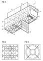
- shows the canopy of
Figure 1 with covering plates attached to the space frame in a perspective view. - Figure 5
- shows a first design of a structured cover plate.
- Figure 6
- shows a second design of a structured cover plate.
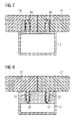
- Figure 7
- shows a first kind of joints between space frame bars and cover plates.
- Figure 8
- shows a second kind of joints between space frame bars and cover plates.
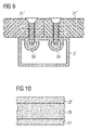
- Figure 9
- shows a third kind of joints between space frame bars and cover plates.
- Figure 10
- shows a section through a covering plate made of a sandwich material.
- An exemplary embodiment of an inventive canopy for a wind turbine nacelle will now be described with respect to the Figures.
Figures 1 to 3 show the space frame of the canopy 1 in a bottom view (Figure 1 ), a side view (Figure 2 ) and a top view (Figure 3 ), respectively. In these Figures, thebars 3 andnodes 5 making up the space frame are shown. - The bottom side of the space frame comprises a circular opening 7 for receiving a tower of a wind turbine. Moreover, the bottom side comprises a
space frame segment 9 of larger dimensions than normalspace frame segments 11. A normal space frame segment in the sense of the present invention is a space frame segment delimited by single space frame bars in each direction. Space frame segments of larger dimensions are formed by removing bars between neighbouringspace frame segments 11 so that structures like the segment oflarger dimensions 9 or similar segments oflarger dimensions Figure 3 ) are formed in the canopy. These structures are at least partly delimited by bars which are themselves assembled by at least two bars and a node between the two bars. - While, in the present embodiment, most of the normal
space frame segments 11 are covered bypolyamide plates 21 the space frame segments of larger dimensions, 9, 13, 15, 17, 19 are covered bypolycarbonate plates 23. These polycarbonate plates comprise hinges so that they form hatches that can be opened, if necessary. In addition, in the present embodiment, thepolycarbonate plates 23 are structured to increase their stiffness. To increase the stiffness of theplates 23, also thepolyamide covering plates 21, can be provided with a structure. Two possible structures are exemplary shown inFigures 5 and 6 . - Those areas of the canopy 1 where an even higher stiffness is needed,
cover plates 25 made of a sandwich material containing a core of aluminium foam are used. Areas where a higher stiffness is needed are typically the area surrounding the opening 7 for the tower, the front side of the canopy, the back side of the canopy and the canopy etches. - In the present embodiment, the cover plates of the canopy consist of transparent polycarbonate hatches 23,
polyamide plates 21 for covering the sides of the canopy frame and aluminium-sandwich-plates 25 which, in the present embodiment, consist ofaluminium layers 27 with alayer 29 of aluminium foam in between (seeFigure 10 ). The connection between the aluminium layers and the foam can be achieved without gluing or welding. - The space frame bars 3 and the
nodes 5 of the present embodiment are made from aluminium but can also be also made from other metals, in particular from steel. The aluminium bars are produced by an extrusion process, which is a very fast and safe process. Moreover, the extrusion process allows for freely designing shapes with functionalities for the aluminium bars. For example, notches, protrusions with or without hooks, screw shapes, holes for bolt connections, etc. can be created. Thenodes 5 can be made by an aluminium pressure die casting process. Like the aluminium bars, the aluminium nodes can be provided with functional shapes, which makes a form closure between the nodes and the bars possible. In the present embodiment, the nodes and the bars are joint by such form closure. In addition, there also glued. However, a form closure or glued joint alone would as well be possible. - If the space frame bars and/or nodes are made from other metal than aluminium, for example from steel, the bars may either be connected directly, i.e. without the use of nodes, by welding, or they made be connected by using die casted steel nodes between the bars. Steel bars for the space frame can, for example, be produced by a hydro forming process which allows for hollow shapes and complex geometries by a single process. In addition, the hydro forming process goes fast and with a high process safety.
- In addition to connecting the bars with each other for forming the space frame, there is also a connection needed for connecting the cover plates to the space frame, in particular to the bars of the space frame.
- If the covering plates are made of a polymer material, like polyamide or polycarbonate, applications like, for example sealings and lights, or joining elements like, for example, holes, flanges, protrusions, notches, etc. can be integrated into the plates. In case of
polycarbonate plates 23 forming hatches, hinges may be integrated into the hatches. The plates made from polyamide or polycarbonate, or other polymer materials, do not show corrosion like metal plates. - Exemplary joints of plates with space frame bars 3 are shown in
Figures 7 to 9 . In all three Figures polyamideplates 21 are shown. However,polycarbonate plates 23 or, in some cases, sandwich plates with aluminium foam could be joint to the space frame bars 3 by the same means as shown in the Fig-ures. In addition to the joining means shown inFigures 7 to 9 joining by glue joints is generally possible. Glue joints can also be present in addition to the joints shown inFig-ures 7 to 9 . -
Figure 7 shows aspace frame bar 3 with twoharpoon beams 31 running along the length of thebar 3. The harpoon beams 31 are realised by protrusions with hooks, which can easily be formed by the extrusion process used for producing the aluminium bars 3 of the present embodiment. Thecover plates 21 comprise integrated joining elements in form ofnotches 33 which can receive the harpoon beams 31 and which have slightly smaller width than the greatest width of the harpoon beams 31. The shape of the hooks is such that peak of the hooks shows away from thebeam 3. In addition, the walls of thenotches 33 integrated into theplates 21 may have the inverse shape of the hooks of the harpoon beams 31. Hence, the hooks do not hinder a movement of the harpoon beams 31 into thenotches 33 of thecover plates 21. On the other hand, a movement of the harpoon beams out of the notches once they are inserted is hindered by the shape of the hooks. Hence, the hooks of the harpoon beams prevent the cover plates from moving away from thealuminium bar 3 once they are fixed to it. -
Figure 8 shows a structure which is inverse to the structure shown inFigure 7 . Instead of protrusions with hooks the aluminium bars 3' show notches the walls of which are equipped with hooks, and the cover plates 21' comprise integrated joining elements in form of protrusions which can be inserted into the notches. The width of the protrusions is slightly larger than the distance between the peaks of the hooks located in the opposing notch walls so that aprotrusion 37 of a cover plate 21' is secured against slipping out of the notch once it is inserted. In addition, the side walls of theprotrusions 37 may have the inverse shape of the notch walls. Note that the wall thickness of the aluminium bar 3' is enlarged at the notch side of the bar. This can easily be achieved by the extrusion process described above. - A further alternative of fixing cover plates to aluminium bars is shown in
Figure 9 . Here, the shownaluminium bar 3" is equipped with acceptances for screws, which can easily be formed by the extrusion process mentioned above. Thecover plates 21" comprise through holes for receivingscrews 41 that can be screwed into theacceptances 39. - In addition to the joints shown in
Figures 7 to 9 further alternative joints are generally possible. For example, thebars 3 may be provided with flanges to whichcover plates - In case of the
sandwich plates 25 with the aluminium foam, joining them to thebars 3 can be accomplished by bolts, by screws (e.g. as shown inFigure 9 ), by gluing, or by a glue joint in combination with a form closure, e.g. provided by protrusion engaging proves. - The proposed design for a canopy of a wind turbine nacelle decreases expedition of efforts in assembling, transport and costs. In particular the aluminium bar extrusion process used for forming the space frame bars is very fast and safe. In addition, also the hydro forming process for forming steel bars is fast and safe. The materials used in the present invention decrease the weight of the canopy without loss of stiffness and loading behaviour. Moreover, due to the reduced corrosion, the durability of the canopy and, hence, a nacelle equipped with such a canopy is increased.
Claims (13)
- Canopy (1) for a wind turbine nacelle, comprising a frame made of bars (3) and covering plates (21, 23, 25), characterised in that- the frame is self supporting,- the bars (3) are made of metal and- the covering plates (21, 23, 25) are made of a material that comprises a polymer material and/or a sandwich material comprising a metal foam (29).
- Canopy (1) as claimed in claim 1,
characterised in that
the bars (3) are made of steel or aluminium. - Canopy (1) as claimed in claim 2,
characterised in that
the bars (3) are made of hydro formed steel or extruded aluminium. - Canopy (1) as claimed in any of the claims 1 to 3, characterised in that
the bars (3) are connected by nodes (5). - Canopy (1) as claimed in any of the claims 1 to 4, characterised in that
the bars (3) and/or nodes (5) are connected to each other by form closure, screw connections, glue connections or weld connections. - Canopy (1) as claimed in any of the claims 1 to 5, characterised in that
at least one of the covering plates (21, 25) is made of a material that comprises a structured polymer material. - Canopy (1) as claimed in any of the claims 1 to 6, characterised in that
at least one covering plate (21, 23, 25) is made of a material that comprises polyamide and/or polycarbonate and/or a sandwich material containing aluminium foam (29). - Canopy (1) as claimed in any of the claims 1 to 7, characterised in that
the bars (3) and the covering plates (21, 23, 25) are glued together. - Canopy (1) as claimed in any of the claims 1 to 8, characterised in that
the bars (3) are made of aluminium and the covering plates are connected to bars (3) by form closure. - Canopy (1) as claimed in any of the claims 1 to 9, characterised in that
the bars (3) are made of aluminium and the covering plates are connected to bars (3) by harpoon beams (31). - Canopy (1) as claimed in any of the claims 1 to 10, characterised in that
the covering plates (21, 23) comprise integrated joining elements (33, 37). - Canopy (1) as claimed in any of the claims 1 to 11, characterised in that
the covering plates comprise integrated applications. - Wind turbine nacelle with a canopy (1) as claimed in any of the claims 1 to 12.
Priority Applications (5)
| Application Number | Priority Date | Filing Date | Title |
|---|---|---|---|
| EP10159129.5A EP2375066B1 (en) | 2010-04-06 | 2010-04-06 | Canopy for a wind turbine nacelle |
| DK10159129.5T DK2375066T3 (en) | 2010-04-06 | 2010-04-06 | Screen for a wind turbine nacelle |
| US13/078,229 US8794928B2 (en) | 2010-04-06 | 2011-04-01 | Canopy for a wind turbine nacelle |
| CA2735609A CA2735609A1 (en) | 2010-04-06 | 2011-04-04 | Canopy for a wind turbine nacelle |
| CN201110085018.2A CN102213189B (en) | 2010-04-06 | 2011-04-06 | Cabin for wind turbine cabin is covered |
Applications Claiming Priority (1)
| Application Number | Priority Date | Filing Date | Title |
|---|---|---|---|
| EP10159129.5A EP2375066B1 (en) | 2010-04-06 | 2010-04-06 | Canopy for a wind turbine nacelle |
Publications (2)
| Publication Number | Publication Date |
|---|---|
| EP2375066A1 true EP2375066A1 (en) | 2011-10-12 |
| EP2375066B1 EP2375066B1 (en) | 2016-06-01 |
Family
ID=43086219
Family Applications (1)
| Application Number | Title | Priority Date | Filing Date |
|---|---|---|---|
| EP10159129.5A Not-in-force EP2375066B1 (en) | 2010-04-06 | 2010-04-06 | Canopy for a wind turbine nacelle |
Country Status (5)
| Country | Link |
|---|---|
| US (1) | US8794928B2 (en) |
| EP (1) | EP2375066B1 (en) |
| CN (1) | CN102213189B (en) |
| CA (1) | CA2735609A1 (en) |
| DK (1) | DK2375066T3 (en) |
Cited By (7)
| Publication number | Priority date | Publication date | Assignee | Title |
|---|---|---|---|---|
| WO2013042621A1 (en) | 2011-09-22 | 2013-03-28 | 三菱重工業株式会社 | Regenerated energy power generation device |
| US8601805B2 (en) | 2011-04-05 | 2013-12-10 | Mitsubishi Heavy Industries, Ltd. | Power generating apparatus of renewable energy type |
| EP2675030A1 (en) | 2012-06-13 | 2013-12-18 | Nordex Energy GmbH | Structural component for a wind turbine blade with a lightning protection conductor |
| KR101374703B1 (en) * | 2013-02-19 | 2014-03-19 | 주식회사 에스컴텍 | The manufacturing method of resin using lattice type form |
| EP3533999A1 (en) * | 2018-03-02 | 2019-09-04 | Siemens Gamesa Renewable Energy A/S | A canopy structure and a wind turbine |
| WO2021013314A1 (en) * | 2019-07-24 | 2021-01-28 | Vestas Wind Systems A/S | Wind turbine nacelle hatch assembly |
| WO2022090061A1 (en) | 2020-10-29 | 2022-05-05 | Jupiter Bach A/S | Nacelle for a wind turbine |
Families Citing this family (9)
| Publication number | Priority date | Publication date | Assignee | Title |
|---|---|---|---|---|
| US20120051898A1 (en) * | 2011-08-05 | 2012-03-01 | General Electric Company | Wind turbine component having a lightweight structure |
| DE102011087161A1 (en) * | 2011-11-26 | 2013-05-29 | Repower Systems Se | Protective cover set and method for packaging a large component |
| US20130183162A1 (en) * | 2012-01-17 | 2013-07-18 | General Electric Company | Nacelle for wind turbine |
| DK178900B1 (en) * | 2012-06-04 | 2017-05-08 | Liftra Ip Aps | Methods and means for establishing access to the main parts of the nacelle on a wind turbine |
| DE102013002528A1 (en) * | 2013-02-13 | 2014-08-14 | Nordex Energy Gmbh | Cladding for a nacelle of a wind turbine |
| US10563395B2 (en) | 2016-06-22 | 2020-02-18 | Vestas Wind Systems A/S | Reinforcement tool for rear frame structure of a wind turbine nacelle |
| EP3475561B1 (en) | 2016-06-22 | 2020-10-14 | Vestas Wind Systems A/S | A wind turbine nacelle comprising a rear frame structure with flexible joints |
| ES2767627T3 (en) | 2016-11-21 | 2020-06-18 | Nordex Energy Gmbh | Gondola for a wind turbine |
| CN112796946B (en) * | 2019-11-14 | 2023-03-24 | 新疆金风科技股份有限公司 | Cabin cover and wind generating set |
Citations (6)
| Publication number | Priority date | Publication date | Assignee | Title |
|---|---|---|---|---|
| DE10340560A1 (en) * | 2003-09-01 | 2005-04-07 | Haase Gfk-Technik Gmbh | Method for constructing housings or enclosures, in particular, for wind power generating installations involves use of three basic types of sandwich-structured modules |
| DE102006001931A1 (en) * | 2006-01-14 | 2007-07-19 | Nordex Energy Gmbh | Housing for gondola of wind energy plant has frame assembled with wall elements so that interior space thereof is defined at least in part by curved faces for better stability |
| WO2007132408A2 (en) * | 2006-05-11 | 2007-11-22 | Jupiter Plast A/S | Modular construction of a nacelle |
| FR2927952A1 (en) * | 2008-02-27 | 2009-08-28 | Snecma Sa | Quasi-cylindrical sound-insulation wall for turbojet engine nacelle in airplane, has alveolar structure with cylindrical configuration without discontinuity, and carried by another structure formed of juxtaposed sectors fixed end to end |
| DE102008027498A1 (en) * | 2008-06-10 | 2009-12-17 | Kenersys Gmbh | Housing for the nacelle of a wind turbine |
| FR2940360A1 (en) * | 2008-12-22 | 2010-06-25 | Aircelle Sa | Acoustic attenuation panel for ducted-fan turbine engine of aircraft, has porous material utilized as acoustic absorption material and attached to structuring skin, and stiffeners fixed on skin, where resistive layer is added on stiffeners |
Family Cites Families (5)
| Publication number | Priority date | Publication date | Assignee | Title |
|---|---|---|---|---|
| DE112005002923A5 (en) | 2004-09-21 | 2007-09-06 | Spaceframe21 Gmbh | Gondola for a wind turbine, slewing for a wind turbine, wind turbine, method for operating a wind turbine |
| CN100513778C (en) | 2004-09-21 | 2009-07-15 | 空间结构21有限公司 | Suspended carriage for wind energy facility, rotary connecting device for wind egergy facility, wind egergy facility, driving method for wind egergy facility |
| CN100460670C (en) | 2006-11-28 | 2009-02-11 | 谢振才 | Multistage wind wheel generator with load supporting type frame |
| JP4959439B2 (en) | 2007-06-22 | 2012-06-20 | 三菱重工業株式会社 | Wind power generator |
| AU2009260465B2 (en) | 2008-05-28 | 2014-09-25 | Stephen David Boyd | Wind diverter |
-
2010
- 2010-04-06 EP EP10159129.5A patent/EP2375066B1/en not_active Not-in-force
- 2010-04-06 DK DK10159129.5T patent/DK2375066T3/en active
-
2011
- 2011-04-01 US US13/078,229 patent/US8794928B2/en not_active Expired - Fee Related
- 2011-04-04 CA CA2735609A patent/CA2735609A1/en not_active Abandoned
- 2011-04-06 CN CN201110085018.2A patent/CN102213189B/en not_active Expired - Fee Related
Patent Citations (6)
| Publication number | Priority date | Publication date | Assignee | Title |
|---|---|---|---|---|
| DE10340560A1 (en) * | 2003-09-01 | 2005-04-07 | Haase Gfk-Technik Gmbh | Method for constructing housings or enclosures, in particular, for wind power generating installations involves use of three basic types of sandwich-structured modules |
| DE102006001931A1 (en) * | 2006-01-14 | 2007-07-19 | Nordex Energy Gmbh | Housing for gondola of wind energy plant has frame assembled with wall elements so that interior space thereof is defined at least in part by curved faces for better stability |
| WO2007132408A2 (en) * | 2006-05-11 | 2007-11-22 | Jupiter Plast A/S | Modular construction of a nacelle |
| FR2927952A1 (en) * | 2008-02-27 | 2009-08-28 | Snecma Sa | Quasi-cylindrical sound-insulation wall for turbojet engine nacelle in airplane, has alveolar structure with cylindrical configuration without discontinuity, and carried by another structure formed of juxtaposed sectors fixed end to end |
| DE102008027498A1 (en) * | 2008-06-10 | 2009-12-17 | Kenersys Gmbh | Housing for the nacelle of a wind turbine |
| FR2940360A1 (en) * | 2008-12-22 | 2010-06-25 | Aircelle Sa | Acoustic attenuation panel for ducted-fan turbine engine of aircraft, has porous material utilized as acoustic absorption material and attached to structuring skin, and stiffeners fixed on skin, where resistive layer is added on stiffeners |
Cited By (8)
| Publication number | Priority date | Publication date | Assignee | Title |
|---|---|---|---|---|
| US8601805B2 (en) | 2011-04-05 | 2013-12-10 | Mitsubishi Heavy Industries, Ltd. | Power generating apparatus of renewable energy type |
| WO2013042621A1 (en) | 2011-09-22 | 2013-03-28 | 三菱重工業株式会社 | Regenerated energy power generation device |
| EP2675030A1 (en) | 2012-06-13 | 2013-12-18 | Nordex Energy GmbH | Structural component for a wind turbine blade with a lightning protection conductor |
| KR101374703B1 (en) * | 2013-02-19 | 2014-03-19 | 주식회사 에스컴텍 | The manufacturing method of resin using lattice type form |
| EP3533999A1 (en) * | 2018-03-02 | 2019-09-04 | Siemens Gamesa Renewable Energy A/S | A canopy structure and a wind turbine |
| US11009008B2 (en) | 2018-03-02 | 2021-05-18 | Siemens Gamesa Renewable Energy A/S | Canopy structure and a wind turbine |
| WO2021013314A1 (en) * | 2019-07-24 | 2021-01-28 | Vestas Wind Systems A/S | Wind turbine nacelle hatch assembly |
| WO2022090061A1 (en) | 2020-10-29 | 2022-05-05 | Jupiter Bach A/S | Nacelle for a wind turbine |
Also Published As
| Publication number | Publication date |
|---|---|
| EP2375066B1 (en) | 2016-06-01 |
| DK2375066T3 (en) | 2016-08-29 |
| US20110243726A1 (en) | 2011-10-06 |
| US8794928B2 (en) | 2014-08-05 |
| CA2735609A1 (en) | 2011-10-06 |
| CN102213189B (en) | 2016-04-13 |
| CN102213189A (en) | 2011-10-12 |
Similar Documents
| Publication | Publication Date | Title |
|---|---|---|
| US8794928B2 (en) | Canopy for a wind turbine nacelle | |
| US8938933B2 (en) | Wall section for a wind turbine tower and wind turbine tower | |
| JP5825531B2 (en) | Opening frame provided on the aircraft fuselage | |
| CN102883940B (en) | For the support unit of self-propelled vehicle | |
| CN205010328U (en) | Articulated stand reinforcement of reinforcement, combination vehicle body structure and pick up car | |
| CN103085739B (en) | Bumper Reinforcement | |
| EP2332761A1 (en) | Battery case | |
| CN101171158A (en) | Energy absorbing parts and automobile bodies using them | |
| CN106458261B (en) | An electric vehicle frame system | |
| FR2595647A1 (en) | SUPPORT LONGERON AND VEHICLE INFRASTRUCTURE CONSTRUCTION | |
| DK2534376T3 (en) | The wall piece for a tower of a wind turbine | |
| CA2960443A1 (en) | Strut linkage for a steel construction, and steel construction having a strut linkage | |
| EP4396894B1 (en) | Housing assembly | |
| EP2700573A2 (en) | A pressurized airplane fuselage, comprising a pressure bulkhead | |
| JP4830017B2 (en) | Bumper structure for passenger cars | |
| CN113597705A (en) | Battery case | |
| EP2070807A2 (en) | Structural member | |
| EP4045797B1 (en) | Nacelle for a wind turbine | |
| KR20220162280A (en) | Side frame for battery case | |
| CZ22189U1 (en) | Vehicle roof luggage carrier | |
| KR101286671B1 (en) | Rear side member assembly for vehicles | |
| JP2019520511A (en) | Aerodynamically shaped member and hydraulically shaped member | |
| EP3324044B1 (en) | Nacelle for a wind turbine | |
| EP2441352B1 (en) | Reinforced shelving upright | |
| GB2537627A (en) | Vehicle Chassis rails and vehicle chassis incorporating the same |
Legal Events
| Date | Code | Title | Description |
|---|---|---|---|
| PUAI | Public reference made under article 153(3) epc to a published international application that has entered the european phase |
Free format text: ORIGINAL CODE: 0009012 |
|
| AK | Designated contracting states |
Kind code of ref document: A1 Designated state(s): AT BE BG CH CY CZ DE DK EE ES FI FR GB GR HR HU IE IS IT LI LT LU LV MC MK MT NL NO PL PT RO SE SI SK SM TR |
|
| AX | Request for extension of the european patent |
Extension state: AL BA ME RS |
|
| 17P | Request for examination filed |
Effective date: 20111107 |
|
| RAP1 | Party data changed (applicant data changed or rights of an application transferred) |
Owner name: SIEMENS AKTIENGESELLSCHAFT |
|
| GRAP | Despatch of communication of intention to grant a patent |
Free format text: ORIGINAL CODE: EPIDOSNIGR1 |
|
| RIC1 | Information provided on ipc code assigned before grant |
Ipc: F03D 11/00 20060101AFI20150930BHEP |
|
| INTG | Intention to grant announced |
Effective date: 20151023 |
|
| GRAS | Grant fee paid |
Free format text: ORIGINAL CODE: EPIDOSNIGR3 |
|
| REG | Reference to a national code |
Ref country code: DE Ref legal event code: R079 Ref document number: 602010033741 Country of ref document: DE Free format text: PREVIOUS MAIN CLASS: F03D0011000000 Ipc: F03D0080100000 |
|
| RIC1 | Information provided on ipc code assigned before grant |
Ipc: F03D 80/80 20160101ALI20160316BHEP Ipc: F03D 80/10 20160101AFI20160316BHEP |
|
| GRAA | (expected) grant |
Free format text: ORIGINAL CODE: 0009210 |
|
| AK | Designated contracting states |
Kind code of ref document: B1 Designated state(s): AT BE BG CH CY CZ DE DK EE ES FI FR GB GR HR HU IE IS IT LI LT LU LV MC MK MT NL NO PL PT RO SE SI SK SM TR |
|
| REG | Reference to a national code |
Ref country code: GB Ref legal event code: FG4D |
|
| REG | Reference to a national code |
Ref country code: CH Ref legal event code: EP Ref country code: AT Ref legal event code: REF Ref document number: 804045 Country of ref document: AT Kind code of ref document: T Effective date: 20160615 |
|
| REG | Reference to a national code |
Ref country code: IE Ref legal event code: FG4D |
|
| REG | Reference to a national code |
Ref country code: DE Ref legal event code: R096 Ref document number: 602010033741 Country of ref document: DE |
|
| REG | Reference to a national code |
Ref country code: DK Ref legal event code: T3 Effective date: 20160823 |
|
| REG | Reference to a national code |
Ref country code: LT Ref legal event code: MG4D |
|
| REG | Reference to a national code |
Ref country code: NL Ref legal event code: MP Effective date: 20160601 |
|
| PG25 | Lapsed in a contracting state [announced via postgrant information from national office to epo] |
Ref country code: FI Free format text: LAPSE BECAUSE OF FAILURE TO SUBMIT A TRANSLATION OF THE DESCRIPTION OR TO PAY THE FEE WITHIN THE PRESCRIBED TIME-LIMIT Effective date: 20160601 Ref country code: NO Free format text: LAPSE BECAUSE OF FAILURE TO SUBMIT A TRANSLATION OF THE DESCRIPTION OR TO PAY THE FEE WITHIN THE PRESCRIBED TIME-LIMIT Effective date: 20160901 Ref country code: LT Free format text: LAPSE BECAUSE OF FAILURE TO SUBMIT A TRANSLATION OF THE DESCRIPTION OR TO PAY THE FEE WITHIN THE PRESCRIBED TIME-LIMIT Effective date: 20160601 |
|
| REG | Reference to a national code |
Ref country code: AT Ref legal event code: MK05 Ref document number: 804045 Country of ref document: AT Kind code of ref document: T Effective date: 20160601 |
|
| PG25 | Lapsed in a contracting state [announced via postgrant information from national office to epo] |
Ref country code: LV Free format text: LAPSE BECAUSE OF FAILURE TO SUBMIT A TRANSLATION OF THE DESCRIPTION OR TO PAY THE FEE WITHIN THE PRESCRIBED TIME-LIMIT Effective date: 20160601 Ref country code: GR Free format text: LAPSE BECAUSE OF FAILURE TO SUBMIT A TRANSLATION OF THE DESCRIPTION OR TO PAY THE FEE WITHIN THE PRESCRIBED TIME-LIMIT Effective date: 20160902 Ref country code: HR Free format text: LAPSE BECAUSE OF FAILURE TO SUBMIT A TRANSLATION OF THE DESCRIPTION OR TO PAY THE FEE WITHIN THE PRESCRIBED TIME-LIMIT Effective date: 20160601 Ref country code: SE Free format text: LAPSE BECAUSE OF FAILURE TO SUBMIT A TRANSLATION OF THE DESCRIPTION OR TO PAY THE FEE WITHIN THE PRESCRIBED TIME-LIMIT Effective date: 20160601 Ref country code: ES Free format text: LAPSE BECAUSE OF FAILURE TO SUBMIT A TRANSLATION OF THE DESCRIPTION OR TO PAY THE FEE WITHIN THE PRESCRIBED TIME-LIMIT Effective date: 20160601 Ref country code: NL Free format text: LAPSE BECAUSE OF FAILURE TO SUBMIT A TRANSLATION OF THE DESCRIPTION OR TO PAY THE FEE WITHIN THE PRESCRIBED TIME-LIMIT Effective date: 20160601 |
|
| PG25 | Lapsed in a contracting state [announced via postgrant information from national office to epo] |
Ref country code: SK Free format text: LAPSE BECAUSE OF FAILURE TO SUBMIT A TRANSLATION OF THE DESCRIPTION OR TO PAY THE FEE WITHIN THE PRESCRIBED TIME-LIMIT Effective date: 20160601 Ref country code: EE Free format text: LAPSE BECAUSE OF FAILURE TO SUBMIT A TRANSLATION OF THE DESCRIPTION OR TO PAY THE FEE WITHIN THE PRESCRIBED TIME-LIMIT Effective date: 20160601 Ref country code: RO Free format text: LAPSE BECAUSE OF FAILURE TO SUBMIT A TRANSLATION OF THE DESCRIPTION OR TO PAY THE FEE WITHIN THE PRESCRIBED TIME-LIMIT Effective date: 20160601 Ref country code: IT Free format text: LAPSE BECAUSE OF FAILURE TO SUBMIT A TRANSLATION OF THE DESCRIPTION OR TO PAY THE FEE WITHIN THE PRESCRIBED TIME-LIMIT Effective date: 20160601 Ref country code: CZ Free format text: LAPSE BECAUSE OF FAILURE TO SUBMIT A TRANSLATION OF THE DESCRIPTION OR TO PAY THE FEE WITHIN THE PRESCRIBED TIME-LIMIT Effective date: 20160601 Ref country code: IS Free format text: LAPSE BECAUSE OF FAILURE TO SUBMIT A TRANSLATION OF THE DESCRIPTION OR TO PAY THE FEE WITHIN THE PRESCRIBED TIME-LIMIT Effective date: 20161001 |
|
| PG25 | Lapsed in a contracting state [announced via postgrant information from national office to epo] |
Ref country code: PT Free format text: LAPSE BECAUSE OF FAILURE TO SUBMIT A TRANSLATION OF THE DESCRIPTION OR TO PAY THE FEE WITHIN THE PRESCRIBED TIME-LIMIT Effective date: 20161003 Ref country code: BE Free format text: LAPSE BECAUSE OF FAILURE TO SUBMIT A TRANSLATION OF THE DESCRIPTION OR TO PAY THE FEE WITHIN THE PRESCRIBED TIME-LIMIT Effective date: 20160601 Ref country code: AT Free format text: LAPSE BECAUSE OF FAILURE TO SUBMIT A TRANSLATION OF THE DESCRIPTION OR TO PAY THE FEE WITHIN THE PRESCRIBED TIME-LIMIT Effective date: 20160601 Ref country code: PL Free format text: LAPSE BECAUSE OF FAILURE TO SUBMIT A TRANSLATION OF THE DESCRIPTION OR TO PAY THE FEE WITHIN THE PRESCRIBED TIME-LIMIT Effective date: 20160601 Ref country code: SM Free format text: LAPSE BECAUSE OF FAILURE TO SUBMIT A TRANSLATION OF THE DESCRIPTION OR TO PAY THE FEE WITHIN THE PRESCRIBED TIME-LIMIT Effective date: 20160601 |
|
| REG | Reference to a national code |
Ref country code: DE Ref legal event code: R097 Ref document number: 602010033741 Country of ref document: DE |
|
| PLBE | No opposition filed within time limit |
Free format text: ORIGINAL CODE: 0009261 |
|
| STAA | Information on the status of an ep patent application or granted ep patent |
Free format text: STATUS: NO OPPOSITION FILED WITHIN TIME LIMIT |
|
| 26N | No opposition filed |
Effective date: 20170302 |
|
| PG25 | Lapsed in a contracting state [announced via postgrant information from national office to epo] |
Ref country code: SI Free format text: LAPSE BECAUSE OF FAILURE TO SUBMIT A TRANSLATION OF THE DESCRIPTION OR TO PAY THE FEE WITHIN THE PRESCRIBED TIME-LIMIT Effective date: 20160601 |
|
| REG | Reference to a national code |
Ref country code: CH Ref legal event code: NV Representative=s name: SIEMENS SCHWEIZ AG, CH Ref country code: CH Ref legal event code: PCOW Free format text: NEW ADDRESS: WERNER-VON-SIEMENS-STRASSE 1, 80333 MUENCHEN (DE) |
|
| REG | Reference to a national code |
Ref country code: DE Ref legal event code: R119 Ref document number: 602010033741 Country of ref document: DE |
|
| REG | Reference to a national code |
Ref country code: DK Ref legal event code: EBP Effective date: 20170430 |
|
| REG | Reference to a national code |
Ref country code: CH Ref legal event code: PL |
|
| GBPC | Gb: european patent ceased through non-payment of renewal fee |
Effective date: 20170406 |
|
| REG | Reference to a national code |
Ref country code: IE Ref legal event code: MM4A |
|
| REG | Reference to a national code |
Ref country code: FR Ref legal event code: ST Effective date: 20171229 |
|
| PG25 | Lapsed in a contracting state [announced via postgrant information from national office to epo] |
Ref country code: DE Free format text: LAPSE BECAUSE OF NON-PAYMENT OF DUE FEES Effective date: 20171103 Ref country code: MC Free format text: LAPSE BECAUSE OF FAILURE TO SUBMIT A TRANSLATION OF THE DESCRIPTION OR TO PAY THE FEE WITHIN THE PRESCRIBED TIME-LIMIT Effective date: 20160601 Ref country code: FR Free format text: LAPSE BECAUSE OF NON-PAYMENT OF DUE FEES Effective date: 20170502 |
|
| PG25 | Lapsed in a contracting state [announced via postgrant information from national office to epo] |
Ref country code: GB Free format text: LAPSE BECAUSE OF NON-PAYMENT OF DUE FEES Effective date: 20170406 Ref country code: LU Free format text: LAPSE BECAUSE OF NON-PAYMENT OF DUE FEES Effective date: 20170406 Ref country code: LI Free format text: LAPSE BECAUSE OF NON-PAYMENT OF DUE FEES Effective date: 20170430 Ref country code: CH Free format text: LAPSE BECAUSE OF NON-PAYMENT OF DUE FEES Effective date: 20170430 |
|
| PG25 | Lapsed in a contracting state [announced via postgrant information from national office to epo] |
Ref country code: DK Free format text: LAPSE BECAUSE OF NON-PAYMENT OF DUE FEES Effective date: 20170430 Ref country code: IE Free format text: LAPSE BECAUSE OF NON-PAYMENT OF DUE FEES Effective date: 20170406 |
|
| PG25 | Lapsed in a contracting state [announced via postgrant information from national office to epo] |
Ref country code: MT Free format text: LAPSE BECAUSE OF NON-PAYMENT OF DUE FEES Effective date: 20170406 |
|
| PG25 | Lapsed in a contracting state [announced via postgrant information from national office to epo] |
Ref country code: HU Free format text: LAPSE BECAUSE OF FAILURE TO SUBMIT A TRANSLATION OF THE DESCRIPTION OR TO PAY THE FEE WITHIN THE PRESCRIBED TIME-LIMIT; INVALID AB INITIO Effective date: 20100406 |
|
| PG25 | Lapsed in a contracting state [announced via postgrant information from national office to epo] |
Ref country code: BG Free format text: LAPSE BECAUSE OF FAILURE TO SUBMIT A TRANSLATION OF THE DESCRIPTION OR TO PAY THE FEE WITHIN THE PRESCRIBED TIME-LIMIT Effective date: 20160601 |
|
| PG25 | Lapsed in a contracting state [announced via postgrant information from national office to epo] |
Ref country code: CY Free format text: LAPSE BECAUSE OF NON-PAYMENT OF DUE FEES Effective date: 20160601 |
|
| PG25 | Lapsed in a contracting state [announced via postgrant information from national office to epo] |
Ref country code: MK Free format text: LAPSE BECAUSE OF FAILURE TO SUBMIT A TRANSLATION OF THE DESCRIPTION OR TO PAY THE FEE WITHIN THE PRESCRIBED TIME-LIMIT Effective date: 20160601 |
|
| PG25 | Lapsed in a contracting state [announced via postgrant information from national office to epo] |
Ref country code: TR Free format text: LAPSE BECAUSE OF FAILURE TO SUBMIT A TRANSLATION OF THE DESCRIPTION OR TO PAY THE FEE WITHIN THE PRESCRIBED TIME-LIMIT Effective date: 20160601 |