EP2375043A2 - Fuel injection control system and program - Google Patents
Fuel injection control system and program Download PDFInfo
- Publication number
- EP2375043A2 EP2375043A2 EP11160127A EP11160127A EP2375043A2 EP 2375043 A2 EP2375043 A2 EP 2375043A2 EP 11160127 A EP11160127 A EP 11160127A EP 11160127 A EP11160127 A EP 11160127A EP 2375043 A2 EP2375043 A2 EP 2375043A2
- Authority
- EP
- European Patent Office
- Prior art keywords
- opening
- fuel injection
- timing
- fuel
- intake valve
- Prior art date
- Legal status (The legal status is an assumption and is not a legal conclusion. Google has not performed a legal analysis and makes no representation as to the accuracy of the status listed.)
- Granted
Links
Images

Classifications
-
- F—MECHANICAL ENGINEERING; LIGHTING; HEATING; WEAPONS; BLASTING
- F02—COMBUSTION ENGINES; HOT-GAS OR COMBUSTION-PRODUCT ENGINE PLANTS
- F02D—CONTROLLING COMBUSTION ENGINES
- F02D41/00—Electrical control of supply of combustible mixture or its constituents
- F02D41/0002—Controlling intake air
-
- F—MECHANICAL ENGINEERING; LIGHTING; HEATING; WEAPONS; BLASTING
- F02—COMBUSTION ENGINES; HOT-GAS OR COMBUSTION-PRODUCT ENGINE PLANTS
- F02D—CONTROLLING COMBUSTION ENGINES
- F02D41/00—Electrical control of supply of combustible mixture or its constituents
- F02D41/30—Controlling fuel injection
- F02D41/32—Controlling fuel injection of the low pressure type
- F02D41/34—Controlling fuel injection of the low pressure type with means for controlling injection timing or duration
- F02D41/345—Controlling injection timing
-
- F—MECHANICAL ENGINEERING; LIGHTING; HEATING; WEAPONS; BLASTING
- F02—COMBUSTION ENGINES; HOT-GAS OR COMBUSTION-PRODUCT ENGINE PLANTS
- F02D—CONTROLLING COMBUSTION ENGINES
- F02D41/00—Electrical control of supply of combustible mixture or its constituents
- F02D41/02—Circuit arrangements for generating control signals
- F02D41/04—Introducing corrections for particular operating conditions
- F02D41/10—Introducing corrections for particular operating conditions for acceleration
-
- Y—GENERAL TAGGING OF NEW TECHNOLOGICAL DEVELOPMENTS; GENERAL TAGGING OF CROSS-SECTIONAL TECHNOLOGIES SPANNING OVER SEVERAL SECTIONS OF THE IPC; TECHNICAL SUBJECTS COVERED BY FORMER USPC CROSS-REFERENCE ART COLLECTIONS [XRACs] AND DIGESTS
- Y02—TECHNOLOGIES OR APPLICATIONS FOR MITIGATION OR ADAPTATION AGAINST CLIMATE CHANGE
- Y02T—CLIMATE CHANGE MITIGATION TECHNOLOGIES RELATED TO TRANSPORTATION
- Y02T10/00—Road transport of goods or passengers
- Y02T10/10—Internal combustion engine [ICE] based vehicles
- Y02T10/12—Improving ICE efficiencies
-
- Y—GENERAL TAGGING OF NEW TECHNOLOGICAL DEVELOPMENTS; GENERAL TAGGING OF CROSS-SECTIONAL TECHNOLOGIES SPANNING OVER SEVERAL SECTIONS OF THE IPC; TECHNICAL SUBJECTS COVERED BY FORMER USPC CROSS-REFERENCE ART COLLECTIONS [XRACs] AND DIGESTS
- Y02—TECHNOLOGIES OR APPLICATIONS FOR MITIGATION OR ADAPTATION AGAINST CLIMATE CHANGE
- Y02T—CLIMATE CHANGE MITIGATION TECHNOLOGIES RELATED TO TRANSPORTATION
- Y02T10/00—Road transport of goods or passengers
- Y02T10/10—Internal combustion engine [ICE] based vehicles
- Y02T10/40—Engine management systems
Definitions
- the present invention relates to a fuel injection control system and a program for controlling a timing of injection of fuel to be injected into the air taken in an engine.
- An object of the present invention is to provide a fuel injection control system and a program for achieving a fuel injection for enhancing both fuel economy and drivability.
- an aspect of the invention as recited in claim 1 provides a fuel injection control system (10) comprising: a throttle valve opening detecting part (34) for detecting opening values of a throttle valve (20) for adjusting an amount of air taken into an engine (22); a fuel injector (26) for injecting fuel into the air taken into the engine (22); a crank angle detecting part (46) for detecting a rotational angle value of a crankshaft (44) of the engine (22); a fuel injection controller (52) for controlling the fuel injector (26) on a basis of the detected opening values of the throttle valve (20) and the detected rotational angle value of the crankshaft (44), wherein the fuel injection controller (52): judges opening and closing states of an intake valve (36), which is provided to the engine (22) and configured to cyclically open and close, on a basis of the rotational angle value of the crankshaft (44); judges that fuel injection is in a fuel economy prioritized condition and controls the fuel injector (26), thereby causing the fuel injector (26) to inject
- An aspect of the invention as recited in claim 2 provides the fuel injection control system (10) according to claim 1, wherein one cycle is defined as an interval of time covering four steps which include an intake step, a compression step, a combustion step, and an exhaust step of the engine (22), the system further comprising a change rate calculator (50) for, in each cycle, calculating the rate of change in the opening values of the throttle valve (20) on a basis of the opening values of the throttle valve (20) which are detected by the throttle valve opening detecting part (34).
- An aspect of the invention as recited in claim 3 provides the fuel injection control system (10) according to any one of claims 1 and 2, wherein once judging that the fuel injection is switched from the fuel economy prioritized condition to the acceleration transition condition, the fuel injection controller (52) controls the fuel injector (26), thereby causing the timing of the fuel injection in the interval of time from the closing of the intake valve (36) to the opening of the intake valve (36) to be gradually delayed to the second timing.
- An aspect of the invention as recited in claim 4 provides the fuel injection control system (10) according to claim 3, wherein the fuel injection controller (52) gradually delays the timing of the fuel injection in the interval of time from the closing of the intake valve (36) to the opening of the intake valve (36) by extending time by which the timing of the current fuel injection is made later than the timing of the preceding fuel injection in accordance with the rate of change in the opening values of the throttle valve (20).
- An aspect of the invention as recited in claim 5 provides the fuel injection control system (10) according to any one of claims 1 to 4, wherein once judging that the fuel injection returns to the fuel economy prioritized condition from the acceleration transition condition, the fuel injection controller (52) controls the fuel injector (26), thereby causing the timing of the fuel injection in the interval of time from the closing of the intake valve (36) to the opening of the intake valve (36) to be gradually advanced to return to the first timing.
- An aspect of the invention as recited in claim 6 provides the fuel injection control system (10) according to claim 5, wherein the fuel injection controller (52) gradually advances the timing of the fuel injection in the interval of time from the closing of the intake valve (36) to the opening of the intake valve (36) by shortening time by which the timing of the current fuel injection is made earlier than the timing of the preceding fuel injection in accordance with the rate of change in the opening values of the throttle valve (20).
- An aspect of the invention as recited in claim 7 provides the fuel injection control system (10) according to any one of claims 1 to 6, wherein while in the acceleration transition condition, if the fuel injection controller (52) judges during the opening of the intake valve (36) that the throttle valve (20) is in the opening state on a basis of the detected opening values of the throttle valve (20), the fuel injection controller (52) controls the fuel injector (26) so that the fuel injector (26) additionally injects the fuel during the opening of the intake valve (36).
- An aspect of the invention as recited in claim 8 provides the fuel injection control system (10) according to claim 7, wherein the fuel injection controller (52) causes an amount of fuel to be injected during the opening of the intake valve (36), the amount corresponding to a difference between one of two opening values and an opening value which is detected when the throttle valve is judged as being in the opening state, the two opening values including: an opening value which is the largest among the opening values used to calculate the rate of change in the opening values of the throttle valve (20); and an opening value which is detected when the fuel injection is judged as being in the acceleration condition.
- an aspect of the invention as recited in claim 9 provides a program causing a computer to function as a fuel injection controller (52), the computer comprising: a throttle valve opening detecting part (34) for detecting opening values of a throttle valve (20) for adjusting an amount of air taken into an engine (22); a fuel injector (26) for injecting fuel into the air taken into the engine (22); and a crank angle detecting part (46) for detecting a rotational angle value of a crankshaft (44) of the engine (22), the fuel injection controller (52) configured to control the fuel injector (26) on a basis of the detected opening values of the throttle valve (20) and the detected rotational angle value of the crankshaft (44), wherein the fuel injection controller (52): judges opening and closing states of an intake valve (36), which is provided to the engine (22) and configured to cyclically open and close, on a basis of the rotational angle value of the crankshaft (44); judges that fuel injection is in a fuel economy prioritized condition and controls the fuel injector (
- the fuel is injected at the first timing following the closing of the intake valve while in the fuel economy prioritized condition; and the fuel is injected at the second timing preceding the opening of the intake valve, or both at the first timing and sometime during the opening of the intake valve (36) while in the acceleration transition condition. For this reason, it is possible to achieve the fuel injection for enhancing both fuel economy and drivability.
- the timing of the fuel injection is gradually delayed to be closer to the second timing from the first timing, when a switch is made from the fuel economy prioritized condition to the acceleration transition condition. For this reason, the torque does not increase immediately, and the drivability can be enhanced further.
- the fuel economy can be enhanced, because the timing of the fuel injection becomes gradually closer to the second timing.
- the time by which to delay the injection timing can be gradually changed in response to the driver's operation of the throttle grip. For this reason, the drivability is further enhanced.
- the timing of the fuel injection is gradually advanced to make the timing of the fuel injection closer to the first timing, when a switch is made from the acceleration transition condition to the fuel economy prioritized condition. For this reason, the torque does not decrease immediately, and the drivability can be further enhanced.
- the time by which to advance the injection timing can be gradually changed in response to the driver's operation of the throttle grip. For this reason, the drivability is further enhanced.
- the fuel is additionally injected during the opening of the intake valve, in a case where the throttle valve is open during the opening of the intake valve. For this reason, the torque is inhibited from decreasing, and the drivability is enhanced.
- the fuel is injected by an amount corresponding to the amount of air having flown into the combustion chamber due to the opening of the throttle valve during the opening of the intake valve. For this reason, it is possible to further inhibit the decrease in the torque, and the drivability is enhanced.
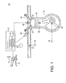
- Fig. 1 is a schematic configuration diagram of a fuel injection control system 10 according to the present invention.
- the fuel injection control system 10 includes: a controller 12 such as an ECU (Engine Control Unit); a handlebar 18 including a throttle grip 14 and a brake lever 16; a throttle valve 20 provided in an air intake pipeline; an engine 22; an injector (fuel injector) 26 for injecting fuel into the air taken in a combustion chamber 24 of the engine 22; and an ignition plug 28 for igniting an air-fuel mixture in the combustion chamber 24 of the engine 22.
- a controller 12 such as an ECU (Engine Control Unit); a handlebar 18 including a throttle grip 14 and a brake lever 16; a throttle valve 20 provided in an air intake pipeline; an engine 22; an injector (fuel injector) 26 for injecting fuel into the air taken in a combustion chamber 24 of the engine 22; and an ignition plug 28 for igniting an air-fuel mixture in the combustion chamber 24 of the engine 22.
- a controller 12 such as an ECU (Engine Control Unit)
- the throttle grip 14 has a structure which is capable of being rotated by a driver.
- a grip opening detecting part 30 detects opening values of the throttle grip 14.
- the driver rotates the throttle grip 14 in an opening direction when wishing acceleration, and rotates the throttle grip 14 in a closing direction when wishing deceleration.
- the controller 12 controls the opening and closing of the throttle valve 20 through an actuator 32 in response to the opening values detected by the grip opening detecting part 30.
- a throttle valve opening detecting part 34 detects opening values of the throttle valve 20.
- the controller 12 controls the throttle valve 20 so that the opening values of the throttle valve 20 can become larger as the opening values detected by the grip opening detecting part 30 becomes larger.
- the throttle valve 20 is a valve for adjusting the amount of air taken into the combustion chamber.
- the injector 26 generates the air-fuel mixture by injecting the fuel to the air which has been taken in through the throttle valve 20 provided in the air intake pipeline.
- the generated air-fuel mixture flows into the combustion chamber 24 of the engine 22, is ignited by the ignition plug 28, and then is exploded.
- the engine 22 converts the explosion energy to a driving force.
- each of the intake valve 36 and the exhaust valve 42 is cyclically performed by the rotation of an unillustrated camshaft.
- the camshaft and a crankshaft 44 are connected together by an unillustrated timing belt. For this reason, as the piston 38 performs the upward and downward reciprocation movements, the crankshaft 44 rotates, and the rotation of the crankshaft 44 is transmitted to the camshaft through the timing belt, whereby the camshaft rotates.
- the timing of the opening or closing of each of the intake valve 36 and the exhaust valve 42 depends on a rotational angle value of the crankshaft 44.
- a crank angle detecting part 46 detects the rotational angle value of the crankshaft.
- the controller 12 includes: a change rate calculator 50 for calculating a rate of change in the opening values of the throttle valve 20 which are detected by the throttle valve opening detecting part 34; and a fuel injection controller 52 for controlling the fuel injection of the injector 26.
- One cycle is defined as an interval of time covering four steps which include the compression step, the combustion step, the exhaust step, and the intake step.
- the change rate calculator 50 calculates the rate of change in the opening values on the basis of the detected opening values of the throttle valve 20.
- the fuel injection controller 52 controls the injector 26, thereby causing the injector 26 to inject the fuel, the control made on the basis of the detected opening values of the throttle valve 20 and the detected rotational angle value of the crankshaft 44.
- the controller 12 controls the time (timing) at which the injector 26 injects the fuel, and a length of time for which the injector 26 injects the fuel.
- the time of the fuel injection (the timing of the fuel injection) mean the timing at which the fuel injection starts.
- the state of fuel atomization varies depending on the timing of fuel injection, and the state of the air-fuel mixture varies accordingly. This state of the air-fuel mixture affects the fuel efficiency and the torque produced by the engine 22.
- the fuel injection controller 52 controls the timing of the fuel injection for the purpose of enhancing the fuel economy and the drivability.
- a computer functions as the controller 12 according to this embodiment by reading a program recorded in an illustrated recording medium.
- the controller 12 starts to capture the opening values of the throttle valve 20 which are detected by the throttle valve opening detecting part 34 and the rotational angle values of the crankshaft 44 which are detected by the crank angle detecting part 46 (in steps S1 and S2 in Fig. 2 ).
- the throttle valve opening detecting part 34 and the crank angle detecting part 46 perform their respective detections in a certain cycle. For this reason, after steps S1 and S2, the controller 12 continues capturing values respectively detected by the throttle valve opening detecting part 34 and the crank angle detecting part 46, although not specifically described.
- the certain cycle means a cycle less than the above-mentioned one cycle.
- one cycle is defined as an interval of time from the closing of the intake valve 36 through the next closing of the intake valve 36.
- one cycle is defined as including the four steps: the compression step, the combustion step, the exhaust step, and the intake step. As described above, the judgment on the opening and closing of the intake valve 36 made from the rotational angle of the crankshaft 44.
- step S3 If the one cycle is judged as not having been completed yet in step S3, the operation stays in step S3 until the one cycle is completed. If the one cycle is judged as having been completed, the change rate calculator 50 calculates the rate of change in the opening values of the throttle valve 20 which are detected until the one cycle is completed (in step S4). In other words, the change rate calculator 50 calculates the rate of change in the opening values of the throttle valve 20 which are detected in the one cycle. In this respect, the rate of change may be calculated from the smallest opening value and the largest opening value among the opening values which are detected in the one cycle. Instead, the rate of change may be calculated from an opening value which is detected for the first time and an opening value which is detected for the last time in the one cycle.
- the fuel injection controller 52 judges whether or not the calculated rate of change in the opening values of the throttle valve 20 falls within a predetermined range (in step S5). If the rate of change in the opening values of the throttle valve 20 falls within the predetermined range, it may be considered that the driver fixes the throttle grip 14 in order to keep the speed almost constant, because the change in the opening values of the throttle grip 14 is small. On the other hand, if the rate of change in the opening values of throttle valve 20 falls outside the predetermined range, it may be considered that the driver operates the throttle grip 14 in the rotational direction in order to change the speed for acceleration or deceleration, because the rate of change in the opening values of throttle grip 14 is large.
- step S5 If having judged in step S5 that the rate of change in the opening values falls within the predetermined range, the fuel injection controller 52 judges that the fuel injection is in a fuel economy prioritized condition. In this case, the operation proceeds to step S6, where the fuel injection controller 52 judges whether or not the timing of the fuel injection in the preceding cycle is a first timing following the closing of the intake valve 36.
- step S6 if having judged that the timing of the fuel injection in the preceding cycle is the first timing, the fuel injection controller 52 sets the timing of the fuel injection in the current cycle at the first timing (in step S7).
- the fuel injection controller 52 controls the injector 26 so that the fuel can be injected at the set timing. Thereby, while in the fuel economy prioritized condition, the fuel can be injected at the timing of the injection which achieves a better fuel economy.
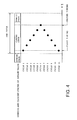
- Fig. 4 is a diagram showing the timing of the fuel injection during the closing of the intake valve 36 in each cycle.
- one cycle is defined as an interval of time from the closing of the intake valve 36 through the next closing of the intake valve 36.
- the first timing is a timing immediately after the closing of the intake valve 36, specifically, a timing predetermined time after the closing of the intake valve 36.
- any timing of the injection may be set at the first timing as far as the timing enables a better fuel economy.
- a second timing is a timing which comes later than the first timing in the interval of time from the closing of the intake valve 36 through the opening of the intake valve 36, specifically, a timing immediately before the opening of the intake valve 36.
- the timing immediately before the opening of the intake valve 36 means a timing predetermined time before the opening of the intake valve 36.
- the second timing is the timing at which the torque of the engine 22, which is produced by the explosion of the air-fuel mixture, becomes stronger. Any timing may be set as the second timing as far as the vehicle body is easy to accelerate at the timing.
- the injection timing which enables the better fuel economy and the injection timing which enhances the drivability are incompatible with each other.
- Black dots shown in Fig. 4 indicate the timing of the fuel injection in each cycle. In Cycle 1, the timing of the fuel injection is set at the first timing.
- step S8 the fuel injection controller 52 judges whether or not the intake valve 36 is currently open. If the fuel injection controller 52 judges, in step S8, that the intake valve 36 is not open, the operation stays in step S8 until the intake valve 36 becomes open. If the fuel injection controller 52 judges that the intake valve 36 is open, the operation proceeds to step S9.
- step S9 the fuel injection controller 52 judges whether or not the throttle valve 20 is open on the basis of the opening values detected by the throttle valve opening detecting part 34. If the fuel injection controller 52 judges in step S9 that the throttle valve 20 is not open, the operation returns to step S1. If the fuel injection controller 52 judges in step S9 that the throttle valve 20 is open, the operation proceeds to step S10.
- the fuel injection controller 52 controls the injector 26 so that the injector 26 can inject the fuel during the opening of the intake valve 36, and the operation returns to step S1.
- the timing of the fuel injection may be any timing during the opening of the intake valve 36 in the current cycle. In a case where the throttle valve 20 is open during the opening of the intake valve 36, more of the air flows into the combustion chamber 24, so that the density of the fuel included in the air-fuel mixture becomes lower. In this case, the torque of the engine 22 which is produced by the explosion of the air-fuel mixture becomes smaller. To avoid this, the fuel injection controller 52 increases the density of the fuel by injecting more fuel. In this respect, the amount of fuel to be injected may be determined from the amount of air additionally having flown into the combustion chamber.
- an amount of fuel may be injected which corresponds to the difference between one of the following three opening values and an opening value detected when the throttle valve 20 is judged as being in the opening state.
- the three opening values include: an opening value which is the largest among the opening values used to calculate the rate of change in the opening values of the throttle valve; an opening value which is the largest among the opening values detected in the preceding cycle; and an opening value detected when the fuel injection is judged as being in an acceleration transition condition, which will be described later.
- step S5 judges in step S5 that the rate of change in the opening values of the throttle valve 20 does not fall within the predetermined range (judges that the rate of change falls outside the predetermined range)
- the driver operates the throttle grip 14 for either acceleration or deceleration. Therefore, in order to judge whether the driver operates the throttle grip 14 for acceleration or deceleration, the fuel injection controller 52 judges whether or not there is an increase between the opening values of the throttle valve 20 (in step S11 in Fig. 3 ). This judgment on whether or not there is an increase between the opening values of the throttle valve 20 may be made, for example, by subtracting an opening value of a previous detection from an opening value of an immediately previous detection among the opening values used to calculate the rate of change in the opening values.
- the judgment on whether or not there is an increase between the opening values of the throttle valve 20 may be made by subtracting an opening value of the first detection from an opening value of the last detection among the opening values detected in the previous cycle. In a case where the driver operates the throttle grip 14 for acceleration, there is an increase between the opening values. In a case where the driver operates the throttle grip 14 for deceleration, there is a decrease between the opening values.
- step S11 If having judged in step S11 that the there is a decrease between the opening values, the fuel injection controller 52 judges that the fuel injection is in the fuel economy prioritized condition, and the operation proceeds to step S 15. On the other hand, if having judged in step S11 that there is an increase between the opening values, the fuel injection controller 52 judges that the fuel injection is in the acceleration transition condition, and the operation proceeds to step S12.
- step S12 the fuel injection controller 52 sets the timing of the fuel injection in the current cycle at a timing obtained by delaying, by first predetermined time, the timing of the fuel injection at which the fuel is injected during the closing of the intake valve 36 in the preceding cycle.
- the fuel injection controller 52 controls the injector 26 so that the injector 26 can inject the fuel at the set timing. This first predetermined time is arbitrary time.
- the timing of the fuel injection can be switched to the second timing in order to increase the torque in the case where the driver rotates the throttle grip 14 for the acceleration.
- the timing of the fuel injection switches from the first timing to the second timing at once, the torque to be outputted increases immediately. This makes the driver feel uncomfortable. For this reason, the timing of the fuel injection is gradually delayed. Thereby, the drivability is further increased, and the fuel economy is enhanced.
- the timing of the fuel injection may be set at the second timing instantaneously instead of making the timing of the fuel injection gradually closer to the second timing.
- step S13 the fuel injection controller 52 judges whether or not the timing set in step S12 is later than the second timing (in step S13). If the fuel injection controller 12 judges in step S 13 that the set timing is not later than the second timing, the operation proceeds to step S8 of Fig. 2 .
- step S 13 if having judged in step S 13 that the set timing is later than the second timing, the fuel injection controller 52 changes the timing of the fuel injection in the current cycle by setting the timing of the fuel injection at the second timing (in step S14), and the operation proceeds to step S8 of Fig. 2 .
- the timing of the fuel injection in the current cycle is limited to the second timing. If the setting is changed, the fuel injection controller 52 controls the injector 26 so that the injector 26 can inject the fuel at the timing obtained by changing the setting.
- step 15 the fuel injection controller 52 sets the timing of the fuel injection in the current cycle at a timing obtained by advancing the timing of the fuel injection during the closing of the intake valve 36 in the preceding cycle by second predetermined time.
- the fuel injection controller 52 controls the injector 26 so that the injector 26 can inject the fuel at the set timing.
- This second predetermined timing is arbitrary time. Furthermore, the first predetermined time and the second predetermined time may be the same or different.
- the timing of the fuel injection can be switched to the first timing in order to improve the fuel economy in cases such as where the driver rotates the throttle grip 14 for the deceleration and where the driver fixes the throttle grip 14 once rotating the throttle grip 14 for the acceleration.
- the timing of the fuel injection switches to the first timing at once from a timing other than the first timing, the torque to be outputted decreases at a dash. This makes the driver feel uncomfortable. For this reason, the timing of the fuel injection is gradually advanced. Thereby, the drivability is further increased.
- the timing of the fuel injection may be set at the first timing instantaneously instead of making the timing of the fuel injection gradually closer to the first timing.
- step S15 the timing set in step S15 is earlier than the first timing (in step S16). If the fuel injection controller 12 judges in step S16 that the set timing is not earlier than the first timing, the operation proceeds to step S8 of Fig. 2 .
- step S16 determines whether the set timing is earlier than the first timing.
- the fuel injection controller 52 changes the timing of the fuel injection in the current cycle by setting the timing of the fuel injection at the first timing (in step S 17), and the operation proceeds to step S8 of Fig. 2 .
- the timing of the fuel injection in the current cycle is limited to the first timing. If the setting is changed, the fuel injection controller 52 controls the injector 26 so that the injector 26 can inject the fuel at the timing obtained by changing the setting.
- the fuel injection controller 52 judges whether the fuel injection is in the fuel economy prioritized condition or the acceleration transition condition on the basis of the opening values of the throttle valve 20. If the fuel injection is in the fuel economy prioritized condition, the fuel injection controller 52 sets the timing of the fuel injection at the first timing which enables the better fuel economy, and thus controls the timing at which the injector 26 injects the fuel. If the fuel injection is in the acceleration transition condition, the fuel injection controller 52 sets the timing of the fuel injection at the second timing which increases the torque, and thus controls the timing at which the injector 26 injects the fuel. For these reasons, it is possible to achieve the fuel injection which enhances both the fuel economy and the drivability.
- the timing of the fuel injection in the interval of time from the closing of the intake valve 36 to the opening of the intake valve 36 is gradually delayed to make the timing of the fuel injection closer to the second timing. For this reason, it is possible to further enhance the drivability, and to enhance the fuel economy as well.
- the timing of the fuel injection in the interval of time from the closing of the intake valve 36 to the opening of the intake valve 36 is gradually advanced to make the timing of the fuel injection closer to the first timing. For this reason, it is possible to further enhance the drivability.
- the torque is inhibited from decreasing, and the drivability is accordingly enhanced because more fuel is injected during the opening of the intake valve 36.
- the time by which the timing of the fuel injection in the preceding cycle is advanced to obtain the timing of the fuel injection in the current cycle is set at the constant time no matter how large the rate of change in the opening values of the throttle valve 20 is.
- the second predetermined time may be changeable, specifically, the second predetermined time may be changed in accordance with the rate of change in the opening values which is calculated in step S4 of Fig. 2 .
- the second predetermined time is set longer when the rate of change in the opening values is large in the decrease direction than when the rate of change in the opening values is small in the decrease direction.
- the time by which the timing of the fuel injection in the current cycle is made to become earlier than the timing of the fuel injection in the preceding cycle is set longer when the rate of change in the opening values is large in the decrease direction than when the rate of change in the opening values is small in the decrease direction.
Landscapes
- Engineering & Computer Science (AREA)
- Chemical & Material Sciences (AREA)
- Combustion & Propulsion (AREA)
- Mechanical Engineering (AREA)
- General Engineering & Computer Science (AREA)
- Electrical Control Of Air Or Fuel Supplied To Internal-Combustion Engine (AREA)
- Combined Controls Of Internal Combustion Engines (AREA)
Abstract
Description
- The present invention relates to a fuel injection control system and a program for controlling a timing of injection of fuel to be injected into the air taken in an engine.
- For a fuel injection system of an engine, control in which a main injection is made at a compression top dead center with a preliminary injection made before opening the intake valve has been heretofore proposed for the purpose of inhibiting the deterioration of fuel economy and exhaust gas emission and facilitating the vaporizing of fuel for the preliminary injection and the mixing of the fuel for the preliminary injection with the fresh air. An example of the technical idea has been shown in Japanese Patent Application Publication No.
2006-342781 - As far as the technical idea described in the above-cited patent document is concerned, it is possible to inhibit the deterioration of the fuel economy and the emission. However, in such as a case where the driver accelerates by opening the throttle between a preliminary injection and a main injection, it is difficult at the timing of the main injection to make an amount of injection meet the drivability, such as acceleration, which a driver expects.
- The present invention has been made with such a conventional problem taken into consideration. An object of the present invention is to provide a fuel injection control system and a program for achieving a fuel injection for enhancing both fuel economy and drivability.
- To achieve the above object, an aspect of the invention as recited in
claim 1 provides a fuel injection control system (10) comprising: a throttle valve opening detecting part (34) for detecting opening values of a throttle valve (20) for adjusting an amount of air taken into an engine (22); a fuel injector (26) for injecting fuel into the air taken into the engine (22); a crank angle detecting part (46) for detecting a rotational angle value of a crankshaft (44) of the engine (22); a fuel injection controller (52) for controlling the fuel injector (26) on a basis of the detected opening values of the throttle valve (20) and the detected rotational angle value of the crankshaft (44), wherein the fuel injection controller (52): judges opening and closing states of an intake valve (36), which is provided to the engine (22) and configured to cyclically open and close, on a basis of the rotational angle value of the crankshaft (44); judges that fuel injection is in a fuel economy prioritized condition and controls the fuel injector (26), thereby causing the fuel injector (26) to inject the fuel at a first timing following closing of the intake valve (36), in a case where a rate of change in the detected opening values of the throttle valve (20) falls within a predetermined range, or in a case where the rate of change in the opening values thereof falls outside the predetermined range and there is a decrease between the opening values of the throttle valve (20); and judges that the fuel injection is in an acceleration transition condition and controls the fuel injector (26), thereby causing the fuel injector (26) to inject the fuel at a second timing preceding opening of the intake valve (36), or both at the first timing and sometime during the opening of the intake valve (36), in a case where the rate of change in the detected opening values of the throttle valve (20) falls outside the predetermined range and there is an increase between the opening values of the throttle valve (20), and
the second timing is a timing later than the first timing in an interval of time from the closing of the intake valve (36) to a subsequent opening of the intake valve (36). - An aspect of the invention as recited in
claim 2 provides the fuel injection control system (10) according toclaim 1, wherein one cycle is defined as an interval of time covering four steps which include an intake step, a compression step, a combustion step, and an exhaust step of the engine (22), the system further comprising a change rate calculator (50) for, in each cycle, calculating the rate of change in the opening values of the throttle valve (20) on a basis of the opening values of the throttle valve (20) which are detected by the throttle valve opening detecting part (34). - An aspect of the invention as recited in
claim 3 provides the fuel injection control system (10) according to any one ofclaims - An aspect of the invention as recited in
claim 4 provides the fuel injection control system (10) according toclaim 3, wherein the fuel injection controller (52) gradually delays the timing of the fuel injection in the interval of time from the closing of the intake valve (36) to the opening of the intake valve (36) by extending time by which the timing of the current fuel injection is made later than the timing of the preceding fuel injection in accordance with the rate of change in the opening values of the throttle valve (20). - An aspect of the invention as recited in
claim 5 provides the fuel injection control system (10) according to any one ofclaims 1 to 4, wherein once judging that the fuel injection returns to the fuel economy prioritized condition from the acceleration transition condition, the fuel injection controller (52) controls the fuel injector (26), thereby causing the timing of the fuel injection in the interval of time from the closing of the intake valve (36) to the opening of the intake valve (36) to be gradually advanced to return to the first timing. - An aspect of the invention as recited in
claim 6 provides the fuel injection control system (10) according toclaim 5, wherein the fuel injection controller (52) gradually advances the timing of the fuel injection in the interval of time from the closing of the intake valve (36) to the opening of the intake valve (36) by shortening time by which the timing of the current fuel injection is made earlier than the timing of the preceding fuel injection in accordance with the rate of change in the opening values of the throttle valve (20). - An aspect of the invention as recited in
claim 7 provides the fuel injection control system (10) according to any one ofclaims 1 to 6, wherein while in the acceleration transition condition, if the fuel injection controller (52) judges during the opening of the intake valve (36) that the throttle valve (20) is in the opening state on a basis of the detected opening values of the throttle valve (20), the fuel injection controller (52) controls the fuel injector (26) so that the fuel injector (26) additionally injects the fuel during the opening of the intake valve (36). - An aspect of the invention as recited in
claim 8 provides the fuel injection control system (10) according toclaim 7, wherein the fuel injection controller (52) causes an amount of fuel to be injected during the opening of the intake valve (36), the amount corresponding to a difference between one of two opening values and an opening value which is detected when the throttle valve is judged as being in the opening state, the two opening values including: an opening value which is the largest among the opening values used to calculate the rate of change in the opening values of the throttle valve (20); and an opening value which is detected when the fuel injection is judged as being in the acceleration condition. - To achieve the above object, an aspect of the invention as recited in
claim 9 provides a program causing a computer to function as a fuel injection controller (52), the computer comprising: a throttle valve opening detecting part (34) for detecting opening values of a throttle valve (20) for adjusting an amount of air taken into an engine (22); a fuel injector (26) for injecting fuel into the air taken into the engine (22); and a crank angle detecting part (46) for detecting a rotational angle value of a crankshaft (44) of the engine (22), the fuel injection controller (52) configured to control the fuel injector (26) on a basis of the detected opening values of the throttle valve (20) and the detected rotational angle value of the crankshaft (44), wherein the fuel injection controller (52): judges opening and closing states of an intake valve (36), which is provided to the engine (22) and configured to cyclically open and close, on a basis of the rotational angle value of the crankshaft (44); judges that fuel injection is in a fuel economy prioritized condition and controls the fuel injector (26), thereby causing the fuel injector (26) to inject the fuel at a first timing following closing of the intake valve (36), in a case where a rate of change in the detected opening values of the throttle valve (20) falls within a predetermined range, or in a case where the rate of change in the opening values thereof falls outside the predetermined range and there is a decrease between the opening values of the throttle valve (20); and judges that the fuel injection is in an acceleration transition condition and controls the fuel injector (26), thereby causing the fuel injector (26) to inject the fuel at a second timing preceding opening of the intake valve (36), or both at the first timing and sometime during the opening of the intake valve (36), in a case where the rate of change in the detected opening values of the throttle valve (20) falls outside the predetermined range and there is an increase between the opening values of the throttle valve (20), and the second timing is a timing later than the first timing in an interval of time from the first timing to the opening of the intake valve (36). - According to the invention as recited in
claims - According to the invention as recited in
claim 3, the timing of the fuel injection is gradually delayed to be closer to the second timing from the first timing, when a switch is made from the fuel economy prioritized condition to the acceleration transition condition. For this reason, the torque does not increase immediately, and the drivability can be enhanced further. In addition, the fuel economy can be enhanced, because the timing of the fuel injection becomes gradually closer to the second timing. - According to the invention as recited in
claim 4, the time by which to delay the injection timing can be gradually changed in response to the driver's operation of the throttle grip. For this reason, the drivability is further enhanced. - According to the invention as recited in
claim 5, the timing of the fuel injection is gradually advanced to make the timing of the fuel injection closer to the first timing, when a switch is made from the acceleration transition condition to the fuel economy prioritized condition. For this reason, the torque does not decrease immediately, and the drivability can be further enhanced. - According to the invention as recited in
claim 6, the time by which to advance the injection timing can be gradually changed in response to the driver's operation of the throttle grip. For this reason, the drivability is further enhanced. - According to the invention as recited in
claim 7, the fuel is additionally injected during the opening of the intake valve, in a case where the throttle valve is open during the opening of the intake valve. For this reason, the torque is inhibited from decreasing, and the drivability is enhanced. - According to the invention as recited in
claim 8, the fuel is injected by an amount corresponding to the amount of air having flown into the combustion chamber due to the opening of the throttle valve during the opening of the intake valve. For this reason, it is possible to further inhibit the decrease in the torque, and the drivability is enhanced. - Further characteristics and advantages of the invention will become apparent from the following description with reference to the drawings wherein:
-
Fig. 1 is a schematic configuration diagram of a fuel injection control system according to the present invention; -
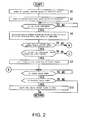
Fig. 2 is a flowchart showing an operation of a controller shown inFig. 1 ; -
Fig. 3 is a flowchart showing an operation of the controller shown inFig. 1 ; and -
Fig. 4 is a diagram showing the timing of fuel injection during the closing of an intake valve in each cycle. - Referring to the attached drawings, detailed descriptions will be hereinbelow provided for a fuel injection control system and a program for causing the fuel injection control system to perform its functions according to the present invention by citing preferable embodiments thereof.
-
Fig. 1 is a schematic configuration diagram of a fuelinjection control system 10 according to the present invention. The fuelinjection control system 10 includes: acontroller 12 such as an ECU (Engine Control Unit); ahandlebar 18 including athrottle grip 14 and abrake lever 16; athrottle valve 20 provided in an air intake pipeline; anengine 22; an injector (fuel injector) 26 for injecting fuel into the air taken in acombustion chamber 24 of theengine 22; and anignition plug 28 for igniting an air-fuel mixture in thecombustion chamber 24 of theengine 22. - The
throttle grip 14 has a structure which is capable of being rotated by a driver. A gripopening detecting part 30 detects opening values of thethrottle grip 14. The driver rotates thethrottle grip 14 in an opening direction when wishing acceleration, and rotates thethrottle grip 14 in a closing direction when wishing deceleration. Thecontroller 12 controls the opening and closing of thethrottle valve 20 through anactuator 32 in response to the opening values detected by the grip opening detectingpart 30. A throttle valveopening detecting part 34 detects opening values of thethrottle valve 20. Thecontroller 12 controls thethrottle valve 20 so that the opening values of thethrottle valve 20 can become larger as the opening values detected by the grip opening detectingpart 30 becomes larger. Thethrottle valve 20 is a valve for adjusting the amount of air taken into the combustion chamber. - The
injector 26 generates the air-fuel mixture by injecting the fuel to the air which has been taken in through thethrottle valve 20 provided in the air intake pipeline. The generated air-fuel mixture flows into thecombustion chamber 24 of theengine 22, is ignited by theignition plug 28, and then is exploded. Theengine 22 converts the explosion energy to a driving force. - Here, brief descriptions will be provided for how the
engine 22 operates. While anintake valve 36 of theengine 22 is being opened, the generated air-fuel mixture flows into the combustion chamber 24 (in an intake step). Apiston 38 performs upward and downward reciprocating movements in acylinder 40. After the air-fuel mixture flows into thecombustion chamber 24, the air-fuel mixture in thecombustion chamber 24 is compressed as thepiston 38 is lifted up (in a compression step). Thereafter, theignition plug 28 ignites the compressed air-fuel mixture, and the air-fuel mixture is accordingly exploded, whereby thepiston 38 descends while accelerated (in a combustion step). Once thepiston 38 is lifted up again, anexhaust valve 42 is opened, and the combustion gas (exhaust gas) existing in thecombustion chamber 24 is discharged (in a discharge step). Theengine 22 repeats this series of four steps; the intake step, the compression step, the combustion step, and the discharge step. - The opening and closing of each of the
intake valve 36 and theexhaust valve 42 is cyclically performed by the rotation of an unillustrated camshaft. The camshaft and acrankshaft 44 are connected together by an unillustrated timing belt. For this reason, as thepiston 38 performs the upward and downward reciprocation movements, thecrankshaft 44 rotates, and the rotation of thecrankshaft 44 is transmitted to the camshaft through the timing belt, whereby the camshaft rotates. By this, the timing of the opening or closing of each of theintake valve 36 and theexhaust valve 42 depends on a rotational angle value of thecrankshaft 44. A crankangle detecting part 46 detects the rotational angle value of the crankshaft. - The
controller 12 includes: achange rate calculator 50 for calculating a rate of change in the opening values of thethrottle valve 20 which are detected by the throttle valveopening detecting part 34; and afuel injection controller 52 for controlling the fuel injection of theinjector 26. One cycle is defined as an interval of time covering four steps which include the compression step, the combustion step, the exhaust step, and the intake step. In each cycle, thechange rate calculator 50 calculates the rate of change in the opening values on the basis of the detected opening values of thethrottle valve 20. Thefuel injection controller 52 controls theinjector 26, thereby causing theinjector 26 to inject the fuel, the control made on the basis of the detected opening values of thethrottle valve 20 and the detected rotational angle value of thecrankshaft 44. - Specifically, the
controller 12 controls the time (timing) at which theinjector 26 injects the fuel, and a length of time for which theinjector 26 injects the fuel. The time of the fuel injection (the timing of the fuel injection) mean the timing at which the fuel injection starts. In this respect, the state of fuel atomization varies depending on the timing of fuel injection, and the state of the air-fuel mixture varies accordingly. This state of the air-fuel mixture affects the fuel efficiency and the torque produced by theengine 22. For this reason, thefuel injection controller 52 controls the timing of the fuel injection for the purpose of enhancing the fuel economy and the drivability. Incidentally, a computer functions as thecontroller 12 according to this embodiment by reading a program recorded in an illustrated recording medium. - Next, descriptions will be provided for the operation of the
controller 12 in accordance with the flowcharts shown inFigs. 2 and3 . Thecontroller 12 starts to capture the opening values of thethrottle valve 20 which are detected by the throttle valveopening detecting part 34 and the rotational angle values of thecrankshaft 44 which are detected by the crank angle detecting part 46 (in steps S1 and S2 inFig. 2 ). The throttle valveopening detecting part 34 and the crankangle detecting part 46 perform their respective detections in a certain cycle. For this reason, after steps S1 and S2, thecontroller 12 continues capturing values respectively detected by the throttle valveopening detecting part 34 and the crankangle detecting part 46, although not specifically described. Here, the certain cycle means a cycle less than the above-mentioned one cycle. - Subsequently, it is judged whether or not the above-mentioned one cycle has been completed (in step S3). In this embodiment, one cycle is defined as an interval of time from the closing of the
intake valve 36 through the next closing of theintake valve 36. In other words, one cycle is defined as including the four steps: the compression step, the combustion step, the exhaust step, and the intake step. As described above, the judgment on the opening and closing of theintake valve 36 made from the rotational angle of thecrankshaft 44. Once the one cycle is completed, the operation proceeds to the next cycle. - If the one cycle is judged as not having been completed yet in step S3, the operation stays in step S3 until the one cycle is completed. If the one cycle is judged as having been completed, the
change rate calculator 50 calculates the rate of change in the opening values of thethrottle valve 20 which are detected until the one cycle is completed (in step S4). In other words, thechange rate calculator 50 calculates the rate of change in the opening values of thethrottle valve 20 which are detected in the one cycle. In this respect, the rate of change may be calculated from the smallest opening value and the largest opening value among the opening values which are detected in the one cycle. Instead, the rate of change may be calculated from an opening value which is detected for the first time and an opening value which is detected for the last time in the one cycle. - Thereafter, the
fuel injection controller 52 judges whether or not the calculated rate of change in the opening values of thethrottle valve 20 falls within a predetermined range (in step S5). If the rate of change in the opening values of thethrottle valve 20 falls within the predetermined range, it may be considered that the driver fixes thethrottle grip 14 in order to keep the speed almost constant, because the change in the opening values of thethrottle grip 14 is small. On the other hand, if the rate of change in the opening values ofthrottle valve 20 falls outside the predetermined range, it may be considered that the driver operates thethrottle grip 14 in the rotational direction in order to change the speed for acceleration or deceleration, because the rate of change in the opening values ofthrottle grip 14 is large. - If having judged in step S5 that the rate of change in the opening values falls within the predetermined range, the
fuel injection controller 52 judges that the fuel injection is in a fuel economy prioritized condition. In this case, the operation proceeds to step S6, where thefuel injection controller 52 judges whether or not the timing of the fuel injection in the preceding cycle is a first timing following the closing of theintake valve 36. In step S6, if having judged that the timing of the fuel injection in the preceding cycle is the first timing, thefuel injection controller 52 sets the timing of the fuel injection in the current cycle at the first timing (in step S7). Thefuel injection controller 52 controls theinjector 26 so that the fuel can be injected at the set timing. Thereby, while in the fuel economy prioritized condition, the fuel can be injected at the timing of the injection which achieves a better fuel economy. -
Fig. 4 is a diagram showing the timing of the fuel injection during the closing of theintake valve 36 in each cycle. As shown inFig. 4 , one cycle is defined as an interval of time from the closing of theintake valve 36 through the next closing of theintake valve 36. The first timing is a timing immediately after the closing of theintake valve 36, specifically, a timing predetermined time after the closing of theintake valve 36. Incidentally, any timing of the injection may be set at the first timing as far as the timing enables a better fuel economy. - In addition, a second timing is a timing which comes later than the first timing in the interval of time from the closing of the
intake valve 36 through the opening of theintake valve 36, specifically, a timing immediately before the opening of theintake valve 36. The timing immediately before the opening of theintake valve 36 means a timing predetermined time before the opening of theintake valve 36. It should be noted that the second timing is the timing at which the torque of theengine 22, which is produced by the explosion of the air-fuel mixture, becomes stronger. Any timing may be set as the second timing as far as the vehicle body is easy to accelerate at the timing. The injection timing which enables the better fuel economy and the injection timing which enhances the drivability are incompatible with each other. The enhancement of the fuel economy deteriorates the drivability, and the enhancement of the drivability deteriorates the fuel economy. Black dots shown inFig. 4 indicate the timing of the fuel injection in each cycle. InCycle 1, the timing of the fuel injection is set at the first timing. - Subsequently, the
fuel injection controller 52 judges whether or not theintake valve 36 is currently open (in step S8). If thefuel injection controller 52 judges, in step S8, that theintake valve 36 is not open, the operation stays in step S8 until theintake valve 36 becomes open. If thefuel injection controller 52 judges that theintake valve 36 is open, the operation proceeds to step S9. - After proceeding to step S9, the
fuel injection controller 52 judges whether or not thethrottle valve 20 is open on the basis of the opening values detected by the throttle valveopening detecting part 34. If thefuel injection controller 52 judges in step S9 that thethrottle valve 20 is not open, the operation returns to step S1. If thefuel injection controller 52 judges in step S9 that thethrottle valve 20 is open, the operation proceeds to step S10. - After proceeding to step 10, the
fuel injection controller 52 controls theinjector 26 so that theinjector 26 can inject the fuel during the opening of theintake valve 36, and the operation returns to step S1. The timing of the fuel injection may be any timing during the opening of theintake valve 36 in the current cycle. In a case where thethrottle valve 20 is open during the opening of theintake valve 36, more of the air flows into thecombustion chamber 24, so that the density of the fuel included in the air-fuel mixture becomes lower. In this case, the torque of theengine 22 which is produced by the explosion of the air-fuel mixture becomes smaller. To avoid this, thefuel injection controller 52 increases the density of the fuel by injecting more fuel. In this respect, the amount of fuel to be injected may be determined from the amount of air additionally having flown into the combustion chamber. - For example, an amount of fuel may be injected which corresponds to the difference between one of the following three opening values and an opening value detected when the
throttle valve 20 is judged as being in the opening state. This makes it possible to inject the amount of fuel which corresponds to the air flowing into thecombustion chamber 24 during the opening of theintake valve 36. Accordingly, the reduction in the torque can be prevented, and the drivability is enhanced. The three opening values include: an opening value which is the largest among the opening values used to calculate the rate of change in the opening values of the throttle valve; an opening value which is the largest among the opening values detected in the preceding cycle; and an opening value detected when the fuel injection is judged as being in an acceleration transition condition, which will be described later. - On the other hand, if the
fuel injection controller 52 judges in step S5 that the rate of change in the opening values of thethrottle valve 20 does not fall within the predetermined range (judges that the rate of change falls outside the predetermined range), the driver operates thethrottle grip 14 for either acceleration or deceleration. Therefore, in order to judge whether the driver operates thethrottle grip 14 for acceleration or deceleration, thefuel injection controller 52 judges whether or not there is an increase between the opening values of the throttle valve 20 (in step S11 inFig. 3 ). This judgment on whether or not there is an increase between the opening values of thethrottle valve 20 may be made, for example, by subtracting an opening value of a previous detection from an opening value of an immediately previous detection among the opening values used to calculate the rate of change in the opening values. Otherwise, the judgment on whether or not there is an increase between the opening values of thethrottle valve 20 may be made by subtracting an opening value of the first detection from an opening value of the last detection among the opening values detected in the previous cycle. In a case where the driver operates thethrottle grip 14 for acceleration, there is an increase between the opening values. In a case where the driver operates thethrottle grip 14 for deceleration, there is a decrease between the opening values. - If having judged in step S11 that the there is a decrease between the opening values, the
fuel injection controller 52 judges that the fuel injection is in the fuel economy prioritized condition, and the operation proceeds to stepS 15. On the other hand, if having judged in step S11 that there is an increase between the opening values, thefuel injection controller 52 judges that the fuel injection is in the acceleration transition condition, and the operation proceeds to step S12. In step S12, thefuel injection controller 52 sets the timing of the fuel injection in the current cycle at a timing obtained by delaying, by first predetermined time, the timing of the fuel injection at which the fuel is injected during the closing of theintake valve 36 in the preceding cycle. Thefuel injection controller 52 controls theinjector 26 so that theinjector 26 can inject the fuel at the set timing. This first predetermined time is arbitrary time. - The timing at which the fuel is injected when the rate of change is judged in step S5 of
Fig. 2 as falling outside the predetermined range and the opening value is judged in step S 11 ofFig. 3 as being increased is shown in each ofCycles 2 to 6 ofFig. 4 . It may be learned fromFig. 4 that: as the cycle moves fromCycles 2 to 6, the timing of the fuel injection becomes later by the first predetermined time than the timing of the fuel injection during the closing of theintake valve 36 in a preceding cycle; and accordingly, the timing of the fuel injection is gradually delayed to come closer to the second timing. That is, when the fuel injection is judged to be changed from the fuel economy prioritized condition to the acceleration transition condition, the timing of the fuel injection gradually lags behind the first timing to come closer to the second timing. - Thereby, control is made so that the timing of the fuel injection can be switched to the second timing in order to increase the torque in the case where the driver rotates the
throttle grip 14 for the acceleration. This enhances the drivability. In addition, if the timing of the fuel injection switches from the first timing to the second timing at once, the torque to be outputted increases immediately. This makes the driver feel uncomfortable. For this reason, the timing of the fuel injection is gradually delayed. Thereby, the drivability is further increased, and the fuel economy is enhanced. Incidentally, in the case where the fuel injection is judged as being in the acceleration transition condition, the timing of the fuel injection may be set at the second timing instantaneously instead of making the timing of the fuel injection gradually closer to the second timing. - Subsequently, the
fuel injection controller 52 judges whether or not the timing set in step S12 is later than the second timing (in step S13). If thefuel injection controller 12 judges in step S 13 that the set timing is not later than the second timing, the operation proceeds to step S8 ofFig. 2 . - On the other hand, if having judged in step S 13 that the set timing is later than the second timing, the
fuel injection controller 52 changes the timing of the fuel injection in the current cycle by setting the timing of the fuel injection at the second timing (in step S14), and the operation proceeds to step S8 ofFig. 2 . In other words, in the case where the timing obtained by delaying the timing of the fuel injection in the preceding cycle by the first predetermined time is later than the second timing, the timing of the fuel injection in the current cycle is limited to the second timing. If the setting is changed, thefuel injection controller 52 controls theinjector 26 so that theinjector 26 can inject the fuel at the timing obtained by changing the setting. - On the other hand, if it is judged that there is no increase between the opening values (that there is a decrease) in step S11, or if the timing of the fuel injection in the preceding cycle is judged in step S6 of
Fig. 2 as not being the first timing, that is to say, if the fuel injection is judged as being in the fuel economy prioritized condition and the timing of the fuel injection in the preceding cycle is not the first timing, the operation proceeds to step 15. Instep 15, thefuel injection controller 52 sets the timing of the fuel injection in the current cycle at a timing obtained by advancing the timing of the fuel injection during the closing of theintake valve 36 in the preceding cycle by second predetermined time. Thefuel injection controller 52 controls theinjector 26 so that theinjector 26 can inject the fuel at the set timing. This second predetermined timing is arbitrary time. Furthermore, the first predetermined time and the second predetermined time may be the same or different. - The timing at which the fuel is injected when the rate of change is judged in step S5 of
Fig. 2 as falling within or outside the predetermined range and it is judged in step S11 ofFig. 3 that there is a decrease in the opening values is shown in each ofCycles 7 to 11 ofFig. 4 . It may be learned fromFig. 4 that: as the cycle moves fromCycles 7 to 11, the timing of the fuel injection becomes earlier by the second predetermined time than the timing of the fuel injection during the closing of theintake valve 36 in a preceding cycle; and accordingly, the timing of the fuel injection is gradually advanced to come closer to the first timing. That is, when the fuel injection is judged to be changed from the acceleration transition condition to the fuel economy prioritized condition, the timing of the fuel injection gradually advanced to come closer to the first timing. - Thereby, control is made so that the timing of the fuel injection can be switched to the first timing in order to improve the fuel economy in cases such as where the driver rotates the
throttle grip 14 for the deceleration and where the driver fixes thethrottle grip 14 once rotating thethrottle grip 14 for the acceleration. In addition, if the timing of the fuel injection switches to the first timing at once from a timing other than the first timing, the torque to be outputted decreases at a dash. This makes the driver feel uncomfortable. For this reason, the timing of the fuel injection is gradually advanced. Thereby, the drivability is further increased. Incidentally, in the case where the fuel injection is judged as being in the fuel economy prioritized condition, the timing of the fuel injection may be set at the first timing instantaneously instead of making the timing of the fuel injection gradually closer to the first timing. - Subsequently, the
fuel injection controller 52 judges whether or not the timing set in step S15 is earlier than the first timing (in step S16). If thefuel injection controller 12 judges in step S16 that the set timing is not earlier than the first timing, the operation proceeds to step S8 ofFig. 2 . - On the other hand, if having judged in step S16 that the set timing is earlier than the first timing, the
fuel injection controller 52 changes the timing of the fuel injection in the current cycle by setting the timing of the fuel injection at the first timing (in step S 17), and the operation proceeds to step S8 ofFig. 2 . In other words, in the case where the timing obtained by advancing the timing of the fuel injection in the preceding cycle by the second predetermined time is earlier than the first timing, the timing of the fuel injection in the current cycle is limited to the first timing. If the setting is changed, thefuel injection controller 52 controls theinjector 26 so that theinjector 26 can inject the fuel at the timing obtained by changing the setting. - As described above, the
fuel injection controller 52 judges whether the fuel injection is in the fuel economy prioritized condition or the acceleration transition condition on the basis of the opening values of thethrottle valve 20. If the fuel injection is in the fuel economy prioritized condition, thefuel injection controller 52 sets the timing of the fuel injection at the first timing which enables the better fuel economy, and thus controls the timing at which theinjector 26 injects the fuel. If the fuel injection is in the acceleration transition condition, thefuel injection controller 52 sets the timing of the fuel injection at the second timing which increases the torque, and thus controls the timing at which theinjector 26 injects the fuel. For these reasons, it is possible to achieve the fuel injection which enhances both the fuel economy and the drivability. - In addition, when a switch is made from the fuel economy prioritized condition to the acceleration transition condition, the timing of the fuel injection in the interval of time from the closing of the
intake valve 36 to the opening of theintake valve 36 is gradually delayed to make the timing of the fuel injection closer to the second timing. For this reason, it is possible to further enhance the drivability, and to enhance the fuel economy as well. - In addition, when a switch is made from the acceleration transition condition to the fuel economy prioritized condition, the timing of the fuel injection in the interval of time from the closing of the
intake valve 36 to the opening of theintake valve 36 is gradually advanced to make the timing of the fuel injection closer to the first timing. For this reason, it is possible to further enhance the drivability. - Moreover, in the case where the
throttle valve 20 is open during the opening of theintake valve 36, the torque is inhibited from decreasing, and the drivability is accordingly enhanced because more fuel is injected during the opening of theintake valve 36. - It should be noted that the foregoing embodiment may be modified into the following modes.
- (1) In the foregoing embodiment, the fuel is to be injected during the opening of the
intake valve 36 once thethrottle valve 20 is opened during the opening of the intake valve 36 (in step S10 ofFig. 2 ) irrespective of whether the fuel injection is in the fuel economy prioritized condition or in the acceleration transition condition. However, the fuel may be injected during the opening of theintake valve 36 once thethrottle valve 20 is opened during the opening of theintake valve 36 only in the case where the fuel injection is judged as being in the acceleration transition condition. In other words, in the case where the fuel injection is judged as being in the fuel economy prioritized condition, no fuel is injected even if thethrottle valve 20 is opened during the opening of theintake valve 36. Thereby, the fuel economy can be further enhanced in the fuel economy prioritized condition. - (2) In the foregoing embodiment, in the case where it is judged in step S11 of
Fig. 3 that there is an increase between the opening values, the timing of the fuel injection in the current cycle is set at the timing obtained by delaying the timing of the fuel injection in the preceding cycle by the first predetermined time (in step S12). However, if it is judged in step S11 ofFig. 3 that there is an increase between the opening values, the fuel injection controller may set the timing of the fuel injection in the current cycle at the first timing and an arbitrary timing during the opening of theintake valve 36 and then the operation may proceed to step S8 ofFig. 2 . Thereby, in the case where there is an increase between the opening values (while in the acceleration transition condition), the fuel is injected twice: at the first timing and at the arbitrary timing during the opening of the intake valve. Specifically, because no large torque is produced from the injection of the fuel at the first timing alone, the fuel is additionally injected at the arbitrary timing during the opening of theintake valve 36 for making up for a lack of the torque while in the acceleration transition condition. In this case, if the rate of change is judged in step S5 ofFig. 2 as falling within the predetermined range, the operation proceeds to step S7 by skipping step S6. Furthermore, if it is judged in step S11 ofFig. 3 that there is no increase between the opening values, the operation proceeds to step S7 ofFig. 2 . - (3) In the foregoing embodiment, in step S12 of
Fig. 3 , the time by which the timing of the fuel injection in the preceding cycle is delayed to obtain the timing of the fuel injection in the current cycle is set at the constant time no matter how large the rate of change in the opening values of thethrottle valve 20 is. However, the first predetermined time may be changeable, specifically, the first predetermined time may be changed in accordance with the rate of change in the opening values which is calculated in step S4 ofFig. 2 . For example, the first predetermined time is set longer when the rate of change in the opening values is large in the increase direction than when the rate of change in the opening values is small in the increase direction. In other words, the time by which the timing of the fuel injection in the current cycle is made to become later than the timing of the fuel injection in the preceding cycle is set longer when the rate of change in the opening values is large in the increase direction than when the rate of change in the opening values is small in the increase direction. Thereby, as the rate of change in the opening values becomes larger in the increase direction, the timing of the fuel injection comes close to the second timing earlier. In the case where the rate of change in the opening values becomes larger in the increase direction, the driver is rotating thethrottle grip 14 to increase the acceleration. For this reason, the drivability is further enhanced by changing the first predetermined time in accordance with the rate of change in the opening values. - In addition, in step S15 of
Fig. 3 , the time by which the timing of the fuel injection in the preceding cycle is advanced to obtain the timing of the fuel injection in the current cycle is set at the constant time no matter how large the rate of change in the opening values of thethrottle valve 20 is. However, the second predetermined time may be changeable, specifically, the second predetermined time may be changed in accordance with the rate of change in the opening values which is calculated in step S4 ofFig. 2 . For example, the second predetermined time is set longer when the rate of change in the opening values is large in the decrease direction than when the rate of change in the opening values is small in the decrease direction. In other words, the time by which the timing of the fuel injection in the current cycle is made to become earlier than the timing of the fuel injection in the preceding cycle is set longer when the rate of change in the opening values is large in the decrease direction than when the rate of change in the opening values is small in the decrease direction. Thereby, as the rate of change in the opening values becomes larger in the decrease direction, the timing of the fuel injection comes close to the first timing earlier. In the case where the rate of change in the opening values becomes larger in the decrease direction, the driver is rotating thethrottle grip 14 to decrease the acceleration. For this reason, the drivability is further enhanced and the fuel economy is improved by changing the second predetermined time in accordance with the rate of change in the opening values. - (4) A mode obtained by combining the above-described modifications (1) to (3) may be adopted.
- The foregoing descriptions have been provided for the preferable embodiments of the present invention. Nevertheless, the technical scope of the present invention is not limited to the descriptions of the foregoing embodiments. It is clear to those skilled in the art that various changes and modifications can be added to the foregoing embodiments. It is clear from the descriptions in the scope of claims that any mode obtained by adding such a change and/or such a modification is included in the technical scope of the present invention as well. In addition, the parenthesized reference numerals included in the scope of claims are provided in accordance with the reference numerals in the attached drawings for the purpose of making the present invention understood easily. The present invention shall not be interpreted or construed by limiting the present invention to the elements denoted by the reference numerals.
-
- 10
- fuel injection control system
- 12
- controller
- 14
- throttle grip
- 16
- brake lever
- 18
- handlebar
- 20
- throttle valve
- 22
- engine
- 24
- combustion chamber
- 26
- injector
- 28
- ignition plug
- 30
- grip opening detecting part
- 32
- actuator
- 34
- throttle valve opening detecting part
- 36
- intake valve
- 38
- piston
- 40
- cylinder
- 42
- exhaust valve
- 44
- crankshaft
- 46
- crank angle detecting part
- 50
- change rate calculator
- 52
- fuel injection controller
Claims (9)
- A fuel injection control system (10) comprising:a throttle valve opening detecting part (34) for detecting opening values of a throttle valve (20) for adjusting an amount of air taken into an engine (22);a fuel injector (26) for injecting fuel into the air taken into the engine (22);a crank angle detecting part (46) for detecting a rotational angle value of a crankshaft (44) of the engine (22);a fuel injection controller (52) for controlling the fuel injector (26) on a basis of the detected opening values of the throttle valve (20) and the detected rotational angle value of the crankshaft (44), whereinthe fuel injection controller (52):judges opening and closing states of an intake valve (36), which is provided to the engine (22) and configured to cyclically open and close, on a basis of the rotational angle value of the crankshaft (44);judges that fuel injection is in a fuel economy prioritized condition and controls the fuel injector (26), thereby causing the fuel injector (26) to inject the fuel at a first timing following closing of the intake valve (36), in a case where a rate of change in the detected opening values of the throttle valve (20) falls within a predetermined range, or in a case where the rate of change in the opening values thereof falls outside the predetermined range and there is a decrease between the opening values of the throttle valve (20); andjudges that the fuel injection is in an acceleration transition condition and controls the fuel injector (26), thereby causing the fuel injector (26) to inject the fuel at a second timing preceding opening of the intake valve (36), or both at the first timing and sometime during the opening of the intake valve (36), in a case where the rate of change in the detected opening values of the throttle valve (20) falls outside the predetermined range and there is an increase between the opening values of the throttle valve (20), andthe second timing is a timing later than the first timing in an interval of time from the closing of the intake valve (36) to a subsequent opening of the intake valve (36).
- The fuel injection control system (10) according to claim 1,
wherein one cycle is defined as an interval of time covering four steps which include a compression step, a combustion step, an exhaust step, and an intake step of the engine (22),
the system further comprising a change rate calculator (50) for, in each cycle, calculating the rate of change in the opening values of the throttle valve (20) on a basis of the opening values of the throttle valve (20) which are detected by the throttle valve opening detecting part (34). - The fuel injection control system (10) according to any one of claims 1 and 2, wherein once judging that the fuel injection is switched from the fuel economy prioritized condition to the acceleration transition condition, the fuel injection controller (52) controls the fuel injector (26), thereby causing the timing of the fuel injection in the interval of time from the closing of the intake valve (36) to the opening of the intake valve (36) to be gradually delayed to the second timing.
- The fuel injection control system (10) according to claim 3, wherein the fuel injection controller (52) gradually delays the timing of the fuel injection in the interval of time from the closing of the intake valve (36) to the opening of the intake valve (36) by extending time by which the timing of the current fuel injection is made later than the timing of the preceding fuel injection in accordance with the rate of change in the opening values of the throttle valve (20).
- The fuel injection control system (10) according to any one of claims 1 to 4, wherein once judging that the fuel injection returns to the fuel economy prioritized condition from the acceleration transition condition, the fuel injection controller (52) controls the fuel injector (26), thereby causing the timing of the fuel injection in the interval of time from the closing of the intake valve (36) to the opening of the intake valve (36) to be gradually advanced to return to the first timing.
- The fuel injection control system (10) according to claim 5, wherein the fuel injection controller (52) gradually advances the timing of the fuel injection in the interval of time from the closing of the intake valve (36) to the opening of the intake valve (36) by shortening time by which the timing of the current fuel injection is made earlier than the timing of the preceding fuel injection in accordance with the rate of change in the opening values of the throttle valve (20).
- The fuel injection control system (10) according to any one of claims 1 to 6, wherein while in the acceleration transition condition, if the fuel injection controller (52) judges during the opening of the intake valve (36) that the throttle valve (20) is in the opening state on a basis of the detected opening values of the throttle valve (20), the fuel injection controller (52) controls the fuel injector (26) so that the fuel injector (26) additionally injects the fuel during the opening of the intake valve (36).
- The fuel injection control system (10) according to claim 7, wherein the fuel injection controller (52) causes an amount of fuel to be injected during the opening of the intake valve (36), the amount corresponding to a difference between one of two opening values and an opening value which is detected when the throttle valve (20) is judged as being in the opening state, the two opening values including: an opening value which is the largest among the opening values used to calculate the rate of change in the opening values of the throttle valve (20); and an opening value which is detected when the fuel injection is judged as being in the acceleration condition.
- A program causing a computer to function as a fuel injection controller (52), the computer comprising:a throttle valve opening detecting part (34) for detecting opening values of a throttle valve (20) for adjusting an amount of air taken into an engine (22);a fuel injector (26) for injecting fuel into the air taken into the engine (22); anda crank angle detecting part (46) for detecting a rotational angle value of a crankshaft (44) of the engine (22),the fuel injection controller (52) configured to control the fuel injector (26) on a basis of the detected opening values of the throttle valve (20) and the detected rotational angle value of the crankshaft (44), whereinthe fuel injection controller (52):judges opening and closing states of an intake valve (36), which is provided to the engine (22) and configured to cyclically open and close, on a basis of the rotational angle value of the crankshaft (44);judges that fuel injection is in a fuel economy prioritized condition and controls the fuel injector (26), thereby causing the fuel injector (26) to inject the fuel at a first timing following closing of the intake valve (36), in a case where a rate of change in the detected opening values of the throttle valve (20) falls within a predetermined range, or in a case where the rate of change in the opening values thereof falls outside the predetermined range and there is a decrease between the opening values of the throttle valve (20); andjudges that the fuel injection is in an acceleration transition condition and controls the fuel injector (26), thereby causing the fuel injector (26) to inject the fuel at a second timing preceding opening of the intake valve (36), or both at the first timing and sometime during the opening of the intake valve (36), in a case where the rate of change in the detected opening values of the throttle valve (20) falls outside the predetermined range and there is an increase between the opening values of the throttle valve (20), andthe second timing is a timing later than the first timing in an interval of time from the first timing to the opening of the intake valve (36).
Applications Claiming Priority (1)
| Application Number | Priority Date | Filing Date | Title |
|---|---|---|---|
| JP2010084648A JP5406103B2 (en) | 2010-03-31 | 2010-03-31 | Fuel injection control device and program |
Publications (3)
| Publication Number | Publication Date |
|---|---|
| EP2375043A2 true EP2375043A2 (en) | 2011-10-12 |
| EP2375043A3 EP2375043A3 (en) | 2018-03-28 |
| EP2375043B1 EP2375043B1 (en) | 2024-08-28 |
Family
ID=43923811
Family Applications (1)
| Application Number | Title | Priority Date | Filing Date |
|---|---|---|---|
| EP11160127.4A Active EP2375043B1 (en) | 2010-03-31 | 2011-03-29 | Fuel injection control system and program |
Country Status (2)
| Country | Link |
|---|---|
| EP (1) | EP2375043B1 (en) |
| JP (1) | JP5406103B2 (en) |
Cited By (1)
| Publication number | Priority date | Publication date | Assignee | Title |
|---|---|---|---|---|
| EP2703627A1 (en) * | 2012-08-29 | 2014-03-05 | Honda Motor Co., Ltd. | Fuel injection control device of saddle-ride type vehicle |
Citations (1)
| Publication number | Priority date | Publication date | Assignee | Title |
|---|---|---|---|---|
| JP2006342781A (en) | 2005-06-10 | 2006-12-21 | Toyota Motor Corp | Control device for internal combustion engine |
Family Cites Families (9)
| Publication number | Priority date | Publication date | Assignee | Title |
|---|---|---|---|---|
| JPS60122238A (en) * | 1983-12-02 | 1985-06-29 | Toyota Motor Corp | Fuel injection method of internal-combustion engine |
| JPS60230531A (en) * | 1984-04-27 | 1985-11-16 | Mazda Motor Corp | Engine equipped with fuel injector |
| JPS61106946A (en) * | 1984-10-30 | 1986-05-24 | Mazda Motor Corp | Fuel injection timing control device |
| JPH06100118B2 (en) * | 1985-10-23 | 1994-12-12 | マツダ株式会社 | Fuel injection timing control device |
| JPS62189348A (en) * | 1986-02-13 | 1987-08-19 | Mazda Motor Corp | Fuel injection control device for engine |
| JPH0799106B2 (en) * | 1987-01-14 | 1995-10-25 | 日産自動車株式会社 | Fuel injection control device for internal combustion engine |
| DE3991570C2 (en) * | 1989-01-20 | 1997-01-30 | Mitsubishi Motors Corp | Fuel supply control method for IC engine |
| JPH07197833A (en) * | 1993-11-25 | 1995-08-01 | Toyota Motor Corp | Fuel injection timing control device for internal combustion engine |
| JP4636564B2 (en) * | 2007-12-17 | 2011-02-23 | 本田技研工業株式会社 | Fuel injection control device |
-
2010
- 2010-03-31 JP JP2010084648A patent/JP5406103B2/en active Active
-
2011
- 2011-03-29 EP EP11160127.4A patent/EP2375043B1/en active Active
Patent Citations (1)
| Publication number | Priority date | Publication date | Assignee | Title |
|---|---|---|---|---|
| JP2006342781A (en) | 2005-06-10 | 2006-12-21 | Toyota Motor Corp | Control device for internal combustion engine |
Cited By (1)
| Publication number | Priority date | Publication date | Assignee | Title |
|---|---|---|---|---|
| EP2703627A1 (en) * | 2012-08-29 | 2014-03-05 | Honda Motor Co., Ltd. | Fuel injection control device of saddle-ride type vehicle |
Also Published As
| Publication number | Publication date |
|---|---|
| EP2375043B1 (en) | 2024-08-28 |
| JP2011214533A (en) | 2011-10-27 |
| JP5406103B2 (en) | 2014-02-05 |
| EP2375043A3 (en) | 2018-03-28 |
Similar Documents
| Publication | Publication Date | Title |
|---|---|---|
| JP4836088B2 (en) | Control device and control method for compression self-ignition internal combustion engine | |
| US8050846B2 (en) | Apparatus and method for controlling engine | |
| JP4306642B2 (en) | Internal combustion engine control system | |
| US7957887B2 (en) | Engine controller | |
| CN107191284B (en) | Engine control device | |
| US9014949B2 (en) | Apparatus for and method of controlling internal combustion engine | |
| US20190249609A1 (en) | Engine control system | |
| CN109555616B (en) | engine control equipment | |
| US6237561B1 (en) | Direct injection engine fuel injection control apparatus and method | |
| JP6090641B2 (en) | Control device for internal combustion engine | |
| EP2375043B1 (en) | Fuel injection control system and program | |
| JP2008031932A (en) | In-cylinder injection spark ignition internal combustion engine | |
| US20170107922A1 (en) | Control system of internal combustion engine | |
| US10113490B2 (en) | Control apparatus for internal combustion engine | |
| US11401885B2 (en) | Engine unit | |
| US20170107916A1 (en) | Control system of internal combustion engine | |
| JP4609279B2 (en) | Control device for internal combustion engine | |
| JP2006132399A (en) | Control device and control method for supercharged engine | |
| US7252057B2 (en) | Apparatus and method for controlling internal combustion engine | |
| JP5338583B2 (en) | Fuel injection control device for internal combustion engine | |
| JP4232601B2 (en) | Fuel injection control device for internal combustion engine | |
| JP4343954B2 (en) | Engine control device | |
| JP4089563B2 (en) | In-cylinder injection engine control device | |
| JP2007278174A (en) | Fuel cut control device for internal combustion engine | |
| JP4321493B2 (en) | Control device for internal combustion engine |
Legal Events
| Date | Code | Title | Description |
|---|---|---|---|
| PUAI | Public reference made under article 153(3) epc to a published international application that has entered the european phase |
Free format text: ORIGINAL CODE: 0009012 |
|
| AK | Designated contracting states |
Kind code of ref document: A2 Designated state(s): AL AT BE BG CH CY CZ DE DK EE ES FI FR GB GR HR HU IE IS IT LI LT LU LV MC MK MT NL NO PL PT RO RS SE SI SK SM TR |
|
| AX | Request for extension of the european patent |
Extension state: BA ME |
|
| PUAL | Search report despatched |
Free format text: ORIGINAL CODE: 0009013 |
|
| AK | Designated contracting states |
Kind code of ref document: A3 Designated state(s): AL AT BE BG CH CY CZ DE DK EE ES FI FR GB GR HR HU IE IS IT LI LT LU LV MC MK MT NL NO PL PT RO RS SE SI SK SM TR |
|
| AX | Request for extension of the european patent |
Extension state: BA ME |
|
| RIC1 | Information provided on ipc code assigned before grant |
Ipc: F02D 41/00 20060101ALN20180221BHEP Ipc: F02D 41/10 20060101ALN20180221BHEP Ipc: F02D 41/34 20060101AFI20180221BHEP Ipc: F02D 41/18 20060101ALN20180221BHEP |
|
| STAA | Information on the status of an ep patent application or granted ep patent |
Free format text: STATUS: REQUEST FOR EXAMINATION WAS MADE |
|
| 17P | Request for examination filed |
Effective date: 20180928 |
|
| RBV | Designated contracting states (corrected) |
Designated state(s): AL AT BE BG CH CY CZ DE DK EE ES FI FR GB GR HR HU IE IS IT LI LT LU LV MC MK MT NL NO PL PT RO RS SE SI SK SM TR |
|
| STAA | Information on the status of an ep patent application or granted ep patent |
Free format text: STATUS: EXAMINATION IS IN PROGRESS |
|
| 17Q | First examination report despatched |
Effective date: 20210917 |
|
| GRAP | Despatch of communication of intention to grant a patent |
Free format text: ORIGINAL CODE: EPIDOSNIGR1 |
|
| STAA | Information on the status of an ep patent application or granted ep patent |
Free format text: STATUS: GRANT OF PATENT IS INTENDED |
|
| RIC1 | Information provided on ipc code assigned before grant |
Ipc: F02D 41/10 20060101ALN20240301BHEP Ipc: F02D 41/00 20060101ALI20240301BHEP Ipc: F02D 41/34 20060101AFI20240301BHEP |
|
| INTG | Intention to grant announced |
Effective date: 20240327 |
|
| RIC1 | Information provided on ipc code assigned before grant |
Ipc: F02D 41/10 20060101ALN20240319BHEP Ipc: F02D 41/00 20060101ALI20240319BHEP Ipc: F02D 41/34 20060101AFI20240319BHEP |
|
| GRAS | Grant fee paid |
Free format text: ORIGINAL CODE: EPIDOSNIGR3 |
|
| GRAA | (expected) grant |
Free format text: ORIGINAL CODE: 0009210 |
|
| STAA | Information on the status of an ep patent application or granted ep patent |
Free format text: STATUS: THE PATENT HAS BEEN GRANTED |
|
| AK | Designated contracting states |
Kind code of ref document: B1 Designated state(s): AL AT BE BG CH CY CZ DE DK EE ES FI FR GB GR HR HU IE IS IT LI LT LU LV MC MK MT NL NO PL PT RO RS SE SI SK SM TR |
|
| REG | Reference to a national code |
Ref country code: GB Ref legal event code: FG4D |
|
| REG | Reference to a national code |
Ref country code: CH Ref legal event code: EP |
|
| REG | Reference to a national code |
Ref country code: DE Ref legal event code: R096 Ref document number: 602011074946 Country of ref document: DE |
|
| REG | Reference to a national code |
Ref country code: IE Ref legal event code: FG4D |
|
| REG | Reference to a national code |
Ref country code: LT Ref legal event code: MG9D |
|
| PG25 | Lapsed in a contracting state [announced via postgrant information from national office to epo] |
Ref country code: NO Free format text: LAPSE BECAUSE OF FAILURE TO SUBMIT A TRANSLATION OF THE DESCRIPTION OR TO PAY THE FEE WITHIN THE PRESCRIBED TIME-LIMIT Effective date: 20241128 |
|
| REG | Reference to a national code |
Ref country code: AT Ref legal event code: MK05 Ref document number: 1718181 Country of ref document: AT Kind code of ref document: T Effective date: 20240828 |
|
| PG25 | Lapsed in a contracting state [announced via postgrant information from national office to epo] |
Ref country code: NL Free format text: LAPSE BECAUSE OF FAILURE TO SUBMIT A TRANSLATION OF THE DESCRIPTION OR TO PAY THE FEE WITHIN THE PRESCRIBED TIME-LIMIT Effective date: 20240828 Ref country code: GR Free format text: LAPSE BECAUSE OF FAILURE TO SUBMIT A TRANSLATION OF THE DESCRIPTION OR TO PAY THE FEE WITHIN THE PRESCRIBED TIME-LIMIT Effective date: 20241129 Ref country code: PT Free format text: LAPSE BECAUSE OF FAILURE TO SUBMIT A TRANSLATION OF THE DESCRIPTION OR TO PAY THE FEE WITHIN THE PRESCRIBED TIME-LIMIT Effective date: 20241230 Ref country code: PL Free format text: LAPSE BECAUSE OF FAILURE TO SUBMIT A TRANSLATION OF THE DESCRIPTION OR TO PAY THE FEE WITHIN THE PRESCRIBED TIME-LIMIT Effective date: 20240828 Ref country code: FI Free format text: LAPSE BECAUSE OF FAILURE TO SUBMIT A TRANSLATION OF THE DESCRIPTION OR TO PAY THE FEE WITHIN THE PRESCRIBED TIME-LIMIT Effective date: 20240828 |
|
| PG25 | Lapsed in a contracting state [announced via postgrant information from national office to epo] |
Ref country code: BG Free format text: LAPSE BECAUSE OF FAILURE TO SUBMIT A TRANSLATION OF THE DESCRIPTION OR TO PAY THE FEE WITHIN THE PRESCRIBED TIME-LIMIT Effective date: 20240828 |
|
| PG25 | Lapsed in a contracting state [announced via postgrant information from national office to epo] |
Ref country code: LV Free format text: LAPSE BECAUSE OF FAILURE TO SUBMIT A TRANSLATION OF THE DESCRIPTION OR TO PAY THE FEE WITHIN THE PRESCRIBED TIME-LIMIT Effective date: 20240828 |
|
| REG | Reference to a national code |
Ref country code: NL Ref legal event code: MP Effective date: 20240828 |
|
| PG25 | Lapsed in a contracting state [announced via postgrant information from national office to epo] |
Ref country code: AT Free format text: LAPSE BECAUSE OF FAILURE TO SUBMIT A TRANSLATION OF THE DESCRIPTION OR TO PAY THE FEE WITHIN THE PRESCRIBED TIME-LIMIT Effective date: 20240828 Ref country code: IS Free format text: LAPSE BECAUSE OF FAILURE TO SUBMIT A TRANSLATION OF THE DESCRIPTION OR TO PAY THE FEE WITHIN THE PRESCRIBED TIME-LIMIT Effective date: 20241228 |
|
| PG25 | Lapsed in a contracting state [announced via postgrant information from national office to epo] |
Ref country code: HR Free format text: LAPSE BECAUSE OF FAILURE TO SUBMIT A TRANSLATION OF THE DESCRIPTION OR TO PAY THE FEE WITHIN THE PRESCRIBED TIME-LIMIT Effective date: 20240828 |
|
| PG25 | Lapsed in a contracting state [announced via postgrant information from national office to epo] |
Ref country code: ES Free format text: LAPSE BECAUSE OF FAILURE TO SUBMIT A TRANSLATION OF THE DESCRIPTION OR TO PAY THE FEE WITHIN THE PRESCRIBED TIME-LIMIT Effective date: 20240828 Ref country code: RS Free format text: LAPSE BECAUSE OF FAILURE TO SUBMIT A TRANSLATION OF THE DESCRIPTION OR TO PAY THE FEE WITHIN THE PRESCRIBED TIME-LIMIT Effective date: 20241128 |
|
| PG25 | Lapsed in a contracting state [announced via postgrant information from national office to epo] |
Ref country code: RS Free format text: LAPSE BECAUSE OF FAILURE TO SUBMIT A TRANSLATION OF THE DESCRIPTION OR TO PAY THE FEE WITHIN THE PRESCRIBED TIME-LIMIT Effective date: 20241128 Ref country code: PT Free format text: LAPSE BECAUSE OF FAILURE TO SUBMIT A TRANSLATION OF THE DESCRIPTION OR TO PAY THE FEE WITHIN THE PRESCRIBED TIME-LIMIT Effective date: 20241230 Ref country code: PL Free format text: LAPSE BECAUSE OF FAILURE TO SUBMIT A TRANSLATION OF THE DESCRIPTION OR TO PAY THE FEE WITHIN THE PRESCRIBED TIME-LIMIT Effective date: 20240828 Ref country code: NO Free format text: LAPSE BECAUSE OF FAILURE TO SUBMIT A TRANSLATION OF THE DESCRIPTION OR TO PAY THE FEE WITHIN THE PRESCRIBED TIME-LIMIT Effective date: 20241128 Ref country code: NL Free format text: LAPSE BECAUSE OF FAILURE TO SUBMIT A TRANSLATION OF THE DESCRIPTION OR TO PAY THE FEE WITHIN THE PRESCRIBED TIME-LIMIT Effective date: 20240828 Ref country code: LV Free format text: LAPSE BECAUSE OF FAILURE TO SUBMIT A TRANSLATION OF THE DESCRIPTION OR TO PAY THE FEE WITHIN THE PRESCRIBED TIME-LIMIT Effective date: 20240828 Ref country code: IS Free format text: LAPSE BECAUSE OF FAILURE TO SUBMIT A TRANSLATION OF THE DESCRIPTION OR TO PAY THE FEE WITHIN THE PRESCRIBED TIME-LIMIT Effective date: 20241228 Ref country code: HR Free format text: LAPSE BECAUSE OF FAILURE TO SUBMIT A TRANSLATION OF THE DESCRIPTION OR TO PAY THE FEE WITHIN THE PRESCRIBED TIME-LIMIT Effective date: 20240828 Ref country code: GR Free format text: LAPSE BECAUSE OF FAILURE TO SUBMIT A TRANSLATION OF THE DESCRIPTION OR TO PAY THE FEE WITHIN THE PRESCRIBED TIME-LIMIT Effective date: 20241129 Ref country code: FI Free format text: LAPSE BECAUSE OF FAILURE TO SUBMIT A TRANSLATION OF THE DESCRIPTION OR TO PAY THE FEE WITHIN THE PRESCRIBED TIME-LIMIT Effective date: 20240828 Ref country code: ES Free format text: LAPSE BECAUSE OF FAILURE TO SUBMIT A TRANSLATION OF THE DESCRIPTION OR TO PAY THE FEE WITHIN THE PRESCRIBED TIME-LIMIT Effective date: 20240828 Ref country code: BG Free format text: LAPSE BECAUSE OF FAILURE TO SUBMIT A TRANSLATION OF THE DESCRIPTION OR TO PAY THE FEE WITHIN THE PRESCRIBED TIME-LIMIT Effective date: 20240828 Ref country code: AT Free format text: LAPSE BECAUSE OF FAILURE TO SUBMIT A TRANSLATION OF THE DESCRIPTION OR TO PAY THE FEE WITHIN THE PRESCRIBED TIME-LIMIT Effective date: 20240828 |
|
| PG25 | Lapsed in a contracting state [announced via postgrant information from national office to epo] |
Ref country code: SM Free format text: LAPSE BECAUSE OF FAILURE TO SUBMIT A TRANSLATION OF THE DESCRIPTION OR TO PAY THE FEE WITHIN THE PRESCRIBED TIME-LIMIT Effective date: 20240828 Ref country code: DK Free format text: LAPSE BECAUSE OF FAILURE TO SUBMIT A TRANSLATION OF THE DESCRIPTION OR TO PAY THE FEE WITHIN THE PRESCRIBED TIME-LIMIT Effective date: 20240828 Ref country code: RO Free format text: LAPSE BECAUSE OF FAILURE TO SUBMIT A TRANSLATION OF THE DESCRIPTION OR TO PAY THE FEE WITHIN THE PRESCRIBED TIME-LIMIT Effective date: 20240828 |
|
| PG25 | Lapsed in a contracting state [announced via postgrant information from national office to epo] |
Ref country code: EE Free format text: LAPSE BECAUSE OF FAILURE TO SUBMIT A TRANSLATION OF THE DESCRIPTION OR TO PAY THE FEE WITHIN THE PRESCRIBED TIME-LIMIT Effective date: 20240828 |
|
| PG25 | Lapsed in a contracting state [announced via postgrant information from national office to epo] |
Ref country code: CZ Free format text: LAPSE BECAUSE OF FAILURE TO SUBMIT A TRANSLATION OF THE DESCRIPTION OR TO PAY THE FEE WITHIN THE PRESCRIBED TIME-LIMIT Effective date: 20240828 |
|
| PG25 | Lapsed in a contracting state [announced via postgrant information from national office to epo] |
Ref country code: SK Free format text: LAPSE BECAUSE OF FAILURE TO SUBMIT A TRANSLATION OF THE DESCRIPTION OR TO PAY THE FEE WITHIN THE PRESCRIBED TIME-LIMIT Effective date: 20240828 Ref country code: IT Free format text: LAPSE BECAUSE OF FAILURE TO SUBMIT A TRANSLATION OF THE DESCRIPTION OR TO PAY THE FEE WITHIN THE PRESCRIBED TIME-LIMIT Effective date: 20240828 |
|
| REG | Reference to a national code |
Ref country code: DE Ref legal event code: R097 Ref document number: 602011074946 Country of ref document: DE |
|
| PLBE | No opposition filed within time limit |
Free format text: ORIGINAL CODE: 0009261 |
|
| STAA | Information on the status of an ep patent application or granted ep patent |
Free format text: STATUS: NO OPPOSITION FILED WITHIN TIME LIMIT |
|
| RAP4 | Party data changed (patent owner data changed or rights of a patent transferred) |
Owner name: HONDA MOTOR CO., LTD. |
|
| 26N | No opposition filed |
Effective date: 20250530 |
|
| PG25 | Lapsed in a contracting state [announced via postgrant information from national office to epo] |
Ref country code: SE Free format text: LAPSE BECAUSE OF FAILURE TO SUBMIT A TRANSLATION OF THE DESCRIPTION OR TO PAY THE FEE WITHIN THE PRESCRIBED TIME-LIMIT Effective date: 20240828 |
|
| PG25 | Lapsed in a contracting state [announced via postgrant information from national office to epo] |
Ref country code: MC Free format text: LAPSE BECAUSE OF FAILURE TO SUBMIT A TRANSLATION OF THE DESCRIPTION OR TO PAY THE FEE WITHIN THE PRESCRIBED TIME-LIMIT Effective date: 20240828 |
|
| REG | Reference to a national code |
Ref country code: CH Ref legal event code: H13 Free format text: ST27 STATUS EVENT CODE: U-0-0-H10-H13 (AS PROVIDED BY THE NATIONAL OFFICE) Effective date: 20251023 |
|
| PG25 | Lapsed in a contracting state [announced via postgrant information from national office to epo] |
Ref country code: LU Free format text: LAPSE BECAUSE OF NON-PAYMENT OF DUE FEES Effective date: 20250329 |
|
| GBPC | Gb: european patent ceased through non-payment of renewal fee |
Effective date: 20250329 |
|
| REG | Reference to a national code |
Ref country code: DE Ref legal event code: R084 Ref document number: 602011074946 Country of ref document: DE |
|
| REG | Reference to a national code |
Ref country code: BE Ref legal event code: MM Effective date: 20250331 |
|
| PG25 | Lapsed in a contracting state [announced via postgrant information from national office to epo] |
Ref country code: GB Free format text: LAPSE BECAUSE OF NON-PAYMENT OF DUE FEES Effective date: 20250329 |
|
| PG25 | Lapsed in a contracting state [announced via postgrant information from national office to epo] |
Ref country code: FR Free format text: LAPSE BECAUSE OF NON-PAYMENT OF DUE FEES Effective date: 20250331 |
|
| PG25 | Lapsed in a contracting state [announced via postgrant information from national office to epo] |
Ref country code: BE Free format text: LAPSE BECAUSE OF NON-PAYMENT OF DUE FEES Effective date: 20250331 |
|
| PG25 | Lapsed in a contracting state [announced via postgrant information from national office to epo] |
Ref country code: CH Free format text: LAPSE BECAUSE OF NON-PAYMENT OF DUE FEES Effective date: 20250331 |
|
| PG25 | Lapsed in a contracting state [announced via postgrant information from national office to epo] |
Ref country code: IE Free format text: LAPSE BECAUSE OF NON-PAYMENT OF DUE FEES Effective date: 20250329 |
|
| PGFP | Annual fee paid to national office [announced via postgrant information from national office to epo] |
Ref country code: DE Payment date: 20260219 Year of fee payment: 16 |
|
| PG25 | Lapsed in a contracting state [announced via postgrant information from national office to epo] |
Ref country code: CY Free format text: LAPSE BECAUSE OF FAILURE TO SUBMIT A TRANSLATION OF THE DESCRIPTION OR TO PAY THE FEE WITHIN THE PRESCRIBED TIME-LIMIT Effective date: 20240828 |
|
| PG25 | Lapsed in a contracting state [announced via postgrant information from national office to epo] |
Ref country code: LT Free format text: LAPSE BECAUSE OF FAILURE TO SUBMIT A TRANSLATION OF THE DESCRIPTION OR TO PAY THE FEE WITHIN THE PRESCRIBED TIME-LIMIT Effective date: 20240828 |
|
| PG25 | Lapsed in a contracting state [announced via postgrant information from national office to epo] |
Ref country code: TR Free format text: LAPSE BECAUSE OF FAILURE TO SUBMIT A TRANSLATION OF THE DESCRIPTION OR TO PAY THE FEE WITHIN THE PRESCRIBED TIME-LIMIT Effective date: 20240828 |