EP2375038A1 - Diagnosis device and method using an in-cylinder pressure sensor in an internal combustion engine - Google Patents
Diagnosis device and method using an in-cylinder pressure sensor in an internal combustion engine Download PDFInfo
- Publication number
- EP2375038A1 EP2375038A1 EP10159322A EP10159322A EP2375038A1 EP 2375038 A1 EP2375038 A1 EP 2375038A1 EP 10159322 A EP10159322 A EP 10159322A EP 10159322 A EP10159322 A EP 10159322A EP 2375038 A1 EP2375038 A1 EP 2375038A1
- Authority
- EP
- European Patent Office
- Prior art keywords
- cylinder
- engine system
- pressure
- engine
- imep
- Prior art date
- Legal status (The legal status is an assumption and is not a legal conclusion. Google has not performed a legal analysis and makes no representation as to the accuracy of the status listed.)
- Granted
Links
Images





Classifications
-
- F—MECHANICAL ENGINEERING; LIGHTING; HEATING; WEAPONS; BLASTING
- F02—COMBUSTION ENGINES; HOT-GAS OR COMBUSTION-PRODUCT ENGINE PLANTS
- F02D—CONTROLLING COMBUSTION ENGINES
- F02D41/00—Electrical control of supply of combustible mixture or its constituents
- F02D41/22—Safety or indicating devices for abnormal conditions
- F02D41/222—Safety or indicating devices for abnormal conditions relating to the failure of sensors or parameter detection devices
-
- F—MECHANICAL ENGINEERING; LIGHTING; HEATING; WEAPONS; BLASTING
- F02—COMBUSTION ENGINES; HOT-GAS OR COMBUSTION-PRODUCT ENGINE PLANTS
- F02D—CONTROLLING COMBUSTION ENGINES
- F02D35/00—Controlling engines, dependent on conditions exterior or interior to engines, not otherwise provided for
-
- F—MECHANICAL ENGINEERING; LIGHTING; HEATING; WEAPONS; BLASTING
- F02—COMBUSTION ENGINES; HOT-GAS OR COMBUSTION-PRODUCT ENGINE PLANTS
- F02D—CONTROLLING COMBUSTION ENGINES
- F02D35/00—Controlling engines, dependent on conditions exterior or interior to engines, not otherwise provided for
- F02D35/02—Controlling engines, dependent on conditions exterior or interior to engines, not otherwise provided for on interior conditions
- F02D35/023—Controlling engines, dependent on conditions exterior or interior to engines, not otherwise provided for on interior conditions by determining the cylinder pressure
-
- F—MECHANICAL ENGINEERING; LIGHTING; HEATING; WEAPONS; BLASTING
- F02—COMBUSTION ENGINES; HOT-GAS OR COMBUSTION-PRODUCT ENGINE PLANTS
- F02D—CONTROLLING COMBUSTION ENGINES
- F02D35/00—Controlling engines, dependent on conditions exterior or interior to engines, not otherwise provided for
- F02D35/02—Controlling engines, dependent on conditions exterior or interior to engines, not otherwise provided for on interior conditions
- F02D35/025—Controlling engines, dependent on conditions exterior or interior to engines, not otherwise provided for on interior conditions by determining temperatures inside the cylinder, e.g. combustion temperatures
-
- F—MECHANICAL ENGINEERING; LIGHTING; HEATING; WEAPONS; BLASTING
- F02—COMBUSTION ENGINES; HOT-GAS OR COMBUSTION-PRODUCT ENGINE PLANTS
- F02D—CONTROLLING COMBUSTION ENGINES
- F02D41/00—Electrical control of supply of combustible mixture or its constituents
- F02D41/22—Safety or indicating devices for abnormal conditions
-
- F—MECHANICAL ENGINEERING; LIGHTING; HEATING; WEAPONS; BLASTING
- F02—COMBUSTION ENGINES; HOT-GAS OR COMBUSTION-PRODUCT ENGINE PLANTS
- F02D—CONTROLLING COMBUSTION ENGINES
- F02D45/00—Electrical control not provided for in groups F02D41/00 - F02D43/00
-
- F—MECHANICAL ENGINEERING; LIGHTING; HEATING; WEAPONS; BLASTING
- F02—COMBUSTION ENGINES; HOT-GAS OR COMBUSTION-PRODUCT ENGINE PLANTS
- F02D—CONTROLLING COMBUSTION ENGINES
- F02D2200/00—Input parameters for engine control
- F02D2200/02—Input parameters for engine control the parameters being related to the engine
- F02D2200/10—Parameters related to the engine output, e.g. engine torque or engine speed
- F02D2200/1002—Output torque
- F02D2200/1004—Estimation of the output torque
-
- F—MECHANICAL ENGINEERING; LIGHTING; HEATING; WEAPONS; BLASTING
- F02—COMBUSTION ENGINES; HOT-GAS OR COMBUSTION-PRODUCT ENGINE PLANTS
- F02D—CONTROLLING COMBUSTION ENGINES
- F02D2200/00—Input parameters for engine control
- F02D2200/02—Input parameters for engine control the parameters being related to the engine
- F02D2200/10—Parameters related to the engine output, e.g. engine torque or engine speed
- F02D2200/1015—Engines misfires
-
- F—MECHANICAL ENGINEERING; LIGHTING; HEATING; WEAPONS; BLASTING
- F02—COMBUSTION ENGINES; HOT-GAS OR COMBUSTION-PRODUCT ENGINE PLANTS
- F02D—CONTROLLING COMBUSTION ENGINES
- F02D2250/00—Engine control related to specific problems or objectives
- F02D2250/08—Engine blow-by from crankcase chamber
-
- F—MECHANICAL ENGINEERING; LIGHTING; HEATING; WEAPONS; BLASTING
- F02—COMBUSTION ENGINES; HOT-GAS OR COMBUSTION-PRODUCT ENGINE PLANTS
- F02D—CONTROLLING COMBUSTION ENGINES
- F02D41/00—Electrical control of supply of combustible mixture or its constituents
- F02D41/02—Circuit arrangements for generating control signals
- F02D41/04—Introducing corrections for particular operating conditions
- F02D41/12—Introducing corrections for particular operating conditions for deceleration
- F02D41/123—Introducing corrections for particular operating conditions for deceleration the fuel injection being cut-off
-
- F—MECHANICAL ENGINEERING; LIGHTING; HEATING; WEAPONS; BLASTING
- F02—COMBUSTION ENGINES; HOT-GAS OR COMBUSTION-PRODUCT ENGINE PLANTS
- F02D—CONTROLLING COMBUSTION ENGINES
- F02D41/00—Electrical control of supply of combustible mixture or its constituents
- F02D41/02—Circuit arrangements for generating control signals
- F02D41/14—Introducing closed-loop corrections
- F02D41/1497—With detection of the mechanical response of the engine
-
- F—MECHANICAL ENGINEERING; LIGHTING; HEATING; WEAPONS; BLASTING
- F02—COMBUSTION ENGINES; HOT-GAS OR COMBUSTION-PRODUCT ENGINE PLANTS
- F02D—CONTROLLING COMBUSTION ENGINES
- F02D41/00—Electrical control of supply of combustible mixture or its constituents
- F02D41/24—Electrical control of supply of combustible mixture or its constituents characterised by the use of digital means
- F02D41/2406—Electrical control of supply of combustible mixture or its constituents characterised by the use of digital means using essentially read only memories
- F02D41/2425—Particular ways of programming the data
- F02D41/2429—Methods of calibrating or learning
- F02D41/2451—Methods of calibrating or learning characterised by what is learned or calibrated
- F02D41/2474—Characteristics of sensors
-
- Y—GENERAL TAGGING OF NEW TECHNOLOGICAL DEVELOPMENTS; GENERAL TAGGING OF CROSS-SECTIONAL TECHNOLOGIES SPANNING OVER SEVERAL SECTIONS OF THE IPC; TECHNICAL SUBJECTS COVERED BY FORMER USPC CROSS-REFERENCE ART COLLECTIONS [XRACs] AND DIGESTS
- Y02—TECHNOLOGIES OR APPLICATIONS FOR MITIGATION OR ADAPTATION AGAINST CLIMATE CHANGE
- Y02T—CLIMATE CHANGE MITIGATION TECHNOLOGIES RELATED TO TRANSPORTATION
- Y02T10/00—Road transport of goods or passengers
- Y02T10/10—Internal combustion engine [ICE] based vehicles
- Y02T10/40—Engine management systems
Definitions
- This invention relates to a vehicle diagnosis device and method.
- the present invention relates to a diagnosis unit for diagnosing faults in a fuel delivery system of a vehicle that cause variations in exhaust emission levels.
- the invention extends to a method of diagnosing faults in the fuel delivery system and to a method of calibrating such a device/method.
- OBD on-board diagnostic
- Accelerometers (referred to as "knock” sensors) have also been widely used for cylinder misfire detection, with the knock sensor output being fed back to the engine control unit which then compensates for the misfire by adjusting operation of the other cylinders.
- Diagnosis techniques such as those described above typically rely on the use of a number of different sensor devices, some of which may be bespoke to the particular diagnosis method.
- a method of diagnosing faults within an engine system comprising: monitoring the output signal of one or more in-cylinder pressure sensors within the engine system, each of the one or more in-cylinder pressure sensors being associated with a cylinder within the engine system; determining a pressure related parameter for a given cylinder having an associated in-cylinder pressure sensor; and diagnosing the presence of faults within the engine system on the basis of the pressure related parameter.
- the present invention recognises that faults within the engine system may be determined by monitoring the pressure signals received from in-cylinder pressure sensors.
- Various pressure related parameters such as the pressure within the cylinder, the Indicated Mean Effective Pressure (IMEP) as calculated from the cylinder pressure or the Top Dead Centre position as calculated from the cylinder pressure may be determined and used to diagnose the presence of faults within the engine system (e.g. sensor drift, overfuelling, cylinder blow-by, cylinder mis-fire etc.).
- the determining step may be performed when the engine system is in a motoring condition and the method may optionally further comprise waiting for a predetermined period of time after the engine system enters the motoring condition. This mitigates against "false" errors being diagnosed because of thermal conditions and intake pressure stabilization.
- the method may further comprise measuring the pressure and temperature within the engine cylinders until predefined testing conditions are satisfied.
- the pressure related parameter may be the indicated mean effective pressure (IMEP) and the determining step may be performed when the engine system is in a motoring condition and the diagnosing step may be arranged to diagnose a sensor drift error if the IMEP value for the given cylinder is outside a predetermined range.
- the pressure related parameter is the indicated mean effective pressure (IMEP) and the diagnosing step comprises comparing determined IMEP values to IMEP values calculated from an engine model.
- the diagnosing step may be arranged to diagnose an over-fuelling condition on the given cylinder if the difference between determined and calculated IMEP values is above a threshold value and if the determined IMEP value is greater than the calculated IMEP value. Furthermore, the diagnosing step may be arranged to diagnose a mis-fire condition on the given cylinder if the difference between determined and calculated IMEP values is above a threshold value and if the calculated IMEP value is greater than the determined IMEP value.
- the pressure related parameter determined in the determining step may be the top-dead-centre (TDC) position of the given cylinder and the diagnosing step may comprise comparing the determined TDC position with predicted TDC position to derive a TDC offset value for the cylinder within the engine system. If an offset is identified this may be used to offset timing demands within the injector associated with the cylinder for which an offset has been identified. Alternatively, the offset may be introduced into an engine control strategy.
- TDC top-dead-centre
- the diagnosing step may be arranged to diagnose a cylinder blow by condition if the TDC offset value exceeds a first threshold.
- TDC offset may vary by -0.5 to +0.5 crank angle degrees. If the offset goes below -0.5 crank angle degrees then a blow-by or compression failure may be diagnosed.
- the diagnosing step may be arranged to diagnose a cylinder sensor drift condition if the TDC offset value exceeds a second threshold. For example, if the offset goes above +0.5 crank angle degrees then a sensor failure may be diagnosed.
- the pressure related parameter determined in the determining step may be the maximum cylinder pressure per engine cycle and the diagnosing step may be arranged to diagnose a compression ratio error condition for the given cylinder if the determined maximum cylinder pressure falls outside a range of values about a reference cylinder pressure.
- the reference cylinder pressures may be stored in a look-up table stored in or associated with the engine control unit. It is noted that the reference values depend on intake manifold absolute pressure.
- each cylinder within the engine system may be associated with an in-cylinder pressure sensor and the method may comprise monitoring the output signal of each in-cylinder pressure sensor within the engine system, determining a pressure related parameter for each cylinder; and diagnosing the presence of faults within the engine system on the basis of the determined pressure related parameter. Furthermore, the method may also comprise outputting an error signal on the basis of the output from the diagnosing step, e.g. for use in engine control.
- an ECU arranged to diagnose faults within an engine system, the engine system comprising a plurality of cylinders, the ECU comprising: monitoring means arranged to monitor the output signal of one or more in-cylinder pressure sensors within the engine system, each of the one or more in-cylinder pressure sensors being associated with a cylinder within the engine system; processing means arranged to determine a pressure related parameter for a given cylinder having an associated in-cylinder pressure sensor and arranged to diagnose the presence of faults within the engine system on the basis of the pressure related parameter.
- the invention extends to a computer readable medium comprising a computer program arranged to configure a computer or an electronic control unit to implement the method according to the first aspect of the present invention.
- the invention also extends to a method of controlling an engine system comprising outputting a TDC offset value as determined in the first aspect of the invention to an engine model for use in engine control.
- combustion takes place within one or more combustion chambers or cylinders, each chamber being defined partly by a reciprocating piston and partly by the walls of a cylinder bore formed in a cylinder head.
- the piston slides within the cylinder so that, when the engine is running, the volume of the combustion chamber cyclically increases and decreases.
- TDC Top Dead Centre
- BDC Bottom Dead Centre
- FIG. 1 shows a representation of an engine system 1 described in the Applicant's co-pending European patent application 08168714.7 .
- the engine system 1 comprises a plurality of cylinders 2. In-cylinder pressure measurements from cylinder pressure sensors 3 are fed (arrow 5) into the vehicle's engine control unit 7.
- the control method in accordance with the system described in the figure is generally represented by the "high level” algorithm box 9, the output of which are injection control variables 11 which are sent to the engine's injectors 13.
- a "low level” algorithm 15 Prior to the sensor output 5 being used by the high level algorithm 9, a "low level” algorithm 15 cleans up the sensor data and calculates a number of combustion parameters which are then used by the high level algorithm 9.
- the in-cylinder pressure measurements may conveniently be over-sampled.
- the oversampled output of the sensors 3 is filtered by a filtering module 17 to produce a raw cylinder pressure array 19.
- the raw array 19 may then be passed to a scaling and diagnostic module 21 which performs pressure measurement pegging and other scaling functions in order to output a corrected pressure array 23.
- a scaling and diagnostic module 21 which performs pressure measurement pegging and other scaling functions in order to output a corrected pressure array 23.
- the corrected pressure array 23 is then sent to a combustion parameters calculation module 25 which calculates a number of combustion parameters as described below which may then be used by an engine model to control engine operation.
- IMEP indicated mean effective pressure
- HRR cumulative heat release rate
- peak pressure and location of peak pressure the pressure derivative with respect to crank angle, DP/D ⁇ , for combustion noise calculations (in particular the max DP/D ⁇ and location of this maximum may be calculated).
- the control method in accordance with the disclosure of EP Application 08168714.7 is, as noted above, generally represented by the "high level" algorithm box 9.
- the control method provides a mechanism for determining fuel quantities via a torque model 27 and for determining injection timings via a combustion centre position model 29. Both models predict injection parameters with reference to one or more mathematical functions (as described below).
- the model coefficients are adjusted with reference to actual measured engine parameters.
- the adjusted model coefficients are permanently stored within the nonvolatile memory 31 of the ECU 7.
- Figures 2 and 3 illustrate the problem of sensor drift that is observed on cylinder pressure sensors after periods of in service use.
- Figure 2 shows a number of traces of cylinder pressure versus crank angle for an engine system in a cold idle state. It can be seen that the various pressure curves do not line up and this represents a drift in the sensor readings that develops after long periods of use.
- Figure 3 shows a similar trace for an engine system that is in a foot-off condition (i.e. a motoring condition). A portion of the figure has been enlarged and it can be seen that the sensor drift corresponds to an offset of a couple of degrees of crank angle at certain points on the pressure curve.
- Figure 4 is a flow chart showing a diagnosis algorithm in accordance with an embodiment of the present invention for use when an engine system is motoring (i.e. a "foot off" condition).
- Step 100 the vehicle ECU initiates the diagnosis algorithm. This initiation could be in response to a driver or maintenance command or alternatively the algorithm could be run periodically.
- Step 102 the ECU performs a check to see if the engine is in a foot-off condition (in other words that the engine is motoring and no fuel is being supplied to the injectors). If the engine is not motoring then the process stops in Step 104.
- Step 106 the ECU checks to make sure that pressure and temperature conditions within the engine are suitable to run the diagnosis algorithm. This step essentially checks that the engine has been in a foot off condition for long enough to allow the diagnosis to run. If the pressure/temperature conditions are not met then the process stops in Step 108.
- Process I is designed to diagnose sensor drift errors.
- Process 11 can either diagnose sensor drift or blow-by errors.
- Process III can diagnose compression errors within the cylinders of the engine.
- Step 110 the ECU first checks in Step 110 whether the output of the pressure sensors has been used to determine the true top dead centre position of the engine cylinders. If a "TDC learn" has not been performed then the process stops in Step 112.
- the process moves to step 114 in which the IMEP value for each cylinder is calculated from the pressure sensors.
- the IMEP value may be calculated by taking pressure values in the interval from 180° of crank angle before TDC to 180° of crank angle after TDC (i.e. the compression and power strokes).
- Step 116 the ECU determines if the calculated IMEP for each cylinder is within a pre-defined range. If all cylinders are within standard operating ranges then the process stops in Step 112.
- Step 118 If one or more cylinders shows an IMEP reading the is outside of the given range then the process returns a sensor drift error in Step 118.
- Step 120 the ECU initially undertakes, in Step 120, a measurement of the maximum cylinder pressure with respect to angular position for each cylinder. This is a statistical measurement performed over a number of engine cycles. This step determines the effective top dead centre position of each cylinder.
- Step 122 the ECU checks to see if the measured TDC position in Step 120 has been compared to the expected TDC position for each cylinder (it is noted that the expected TDC position may be pre-loaded and stored on the ECU). If the offset from the expected TDC position has not yet been determined then, in Step 124, the ECU determines the offset between the measured and expected values. It is noted that due to heat losses the maximum pressure in a cylinder of a motoring engine is approximately 1 crank angle degree before the geometric top dead centre of the cylinder. The offset that is calculated by the ECU is therefore with respect to the thermodynamic TDC position (1° crank angle before geometric TDC).
- Step 126 the difference from the previous offset calculation is determined for each cylinder.
- Step 128 the variation in the offset is assessed for each cylinder. If the variation is within pre-defined limits then the diagnosis process ends in Step 130.
- the ECU may determine that there is a blow-by error in the cylinder under evaluation (Step 132). If the offset variation is above the second threshold (e.g. if the TDC offset rises above 0.5 crank angle degrees from the initial learn TDC offset) then a sensor drift error is output (Step 118) for that cylinder.
- a first threshold e.g. if the TDC offset drops below 0.5 crank angle degrees from the initial learn TDC offset
- the ECU may determine that there is a blow-by error in the cylinder under evaluation (Step 132). If the offset variation is above the second threshold (e.g. if the TDC offset rises above 0.5 crank angle degrees from the initial learn TDC offset) then a sensor drift error is output (Step 118) for that cylinder.
- Step 134 determines the maximum pressure measurement for each cylinder and in Step 136 determines if the pressure values are within a pre-determined range. If the values are in range then the diagnosis process stops in Step 138. If the pressure value on any cylinder is outside of the pre-determined range then the diagnosis process returns a compression ratio error for the cylinder in question (Step 140).
- Figure 5 shows an example of cylinder pressure sensor drift that may be detected by the diagnosis method according to an embodiment of the present invention.
- the figure illustrates the results of the analysis of computed IMEP versus air mass flow in foot off driving conditions with coolant temperature in the range 0-80°C. It can be seen that three of the four cylinder sensors return IMEP readings within the valid, boxed region 150. The sensor on cylinder 3 however is defective due to a wrongly measured IMEP (see circled area 152).
- Figure 6 illustrates the diagnosis process that may be performed during normal operating conditions (i.e. when the injectors are receiving and injecting fuel into the engine).
- Step 200 the diagnosis process is started and in Step 202 the ECU checks that the engine is in a running mode. If no then the diagnostic process ends in Step 104. The ECU then checks, in Step 106, whether the vehicle is in a motoring (foot off condition). If the engine is motoring then the process terminates in Step 108. Finally, the ECU checks, in Step 110, whether the top dead centre position has been determined. If TDC has not been determined then the process terminates in Step 112.
- Step 214 the pressure signals from the pressure sensors in each cylinder are used to measure the IMEP within each cylinder over time, i.e. over N cycles.
- Step 216 a ratio of measured to estimated IMEP is calculated. It is therefore noted that in Step 216 an estimated IMEP value based on the current engine operating conditions is either calculated or received by the ECU 7. It is noted that the Applicant's co-pending European patent application 08168714.7 relates to an engine control model in which parameters such as the IMEP for each cylinder are calculated.
- Step 218 the ECU checks whether the ratio of measured to estimated IMEP is within a given range. If the ratio is less than a first threshold value (Step 220) then a misfiring fault is returned for the cylinder in question. If the ratio is determined to exceed a second threshold (Step 222) then an over fuelling fault is returned for the cylinder in question. If the ratio is within the predetermined allowable range then the diagnosis process terminates in Step 224.
- Figure 7 represents a misfiring error on a cylinder (IMEP variations in the bottom trace denote the effects of a misfire).
- Figures 8 and 9 are general representations of an engine control unit suitable for use with the present invention and a flow chart representing the basic method according to the present invention.
- an ECU 7 comprises monitoring means 300 and processing means 302.
- the method according to an embodiment of the present invention comprises monitoring 310 the output of in-cylinder pressure sensors, determining 312 a pressure related parameter and diagnosing 314 faults within the engine system.
Landscapes
- Engineering & Computer Science (AREA)
- Chemical & Material Sciences (AREA)
- Combustion & Propulsion (AREA)
- Mechanical Engineering (AREA)
- General Engineering & Computer Science (AREA)
- Combined Controls Of Internal Combustion Engines (AREA)
Abstract
Description
- This invention relates to a vehicle diagnosis device and method. In particular, the present invention relates to a diagnosis unit for diagnosing faults in a fuel delivery system of a vehicle that cause variations in exhaust emission levels. The invention extends to a method of diagnosing faults in the fuel delivery system and to a method of calibrating such a device/method.
- With the introduction of stricter emission regulations (particularly in the USA), on-board diagnostic (OBD) requirements have emerged aimed at indicating faults causing excessive vehicle emission levels (emission threshold based diagnosis). These requirements include identification of the source of the fault for a quick and guided repair of the problem.
- One of the systems requiring fault indication is the vehicle's fuel delivery system. Regulations require diagnosis of fuel injection quantity, pressure and timing fault types which may cause either an increase/decrease in the quality/quantity of combustion and thus a variation in the emission levels. It is noted that any fault diagnosis system/method needs to work reliably across the full range of operation of a vehicle's engine (speed and load) and be robust to variations in ambient conditions, driving conditions and style and fuel quality.
- Variations in the fuel injection quantity, cylinder pressure and injection timing (of which misfire is an extreme case) cause a change in the rotational speed of the engine crankshaft. Current crank (shaft) speed misfire diagnostic methods exploit this by comparing the average engine speed over one cylinder to the next. These methods vary in the number of crank teeth over which the average engine speed is calculated, but the principle remains the same in that the diagnosis is made by detecting when the misfiring of a cylinder causes a deceleration in its rotational speed relative to the adjacent cylinder(s) (Note: adjacent in this context means adjacent in the firing order and not necessarily physically adjacent).
- Accelerometers (referred to as "knock" sensors) have also been widely used for cylinder misfire detection, with the knock sensor output being fed back to the engine control unit which then compensates for the misfire by adjusting operation of the other cylinders.
- Diagnosis techniques such as those described above typically rely on the use of a number of different sensor devices, some of which may be bespoke to the particular diagnosis method.
- It is an object of the present invention to provide a diagnostic system or method which allows reliable diagnosis or identification of fault conditions within an engine fuel system across the full range of operation of the vehicle's engine. It is a further object of the present invention to provide a diagnosis method that can diagnose a range of vehicle faults such as compression ratio errors, blow by errors, engine misfire and over-fuelling conditions. It is a yet further object of the present invention to provide a diagnosis method that can self-diagnose faults within the sensor system, for example sensor drift.
- According to a first aspect of the present invention there is provided a method of diagnosing faults within an engine system, the engine system comprising a plurality of cylinders, the method comprising: monitoring the output signal of one or more in-cylinder pressure sensors within the engine system, each of the one or more in-cylinder pressure sensors being associated with a cylinder within the engine system; determining a pressure related parameter for a given cylinder having an associated in-cylinder pressure sensor; and diagnosing the presence of faults within the engine system on the basis of the pressure related parameter.
- The present invention recognises that faults within the engine system may be determined by monitoring the pressure signals received from in-cylinder pressure sensors. Various pressure related parameters such as the pressure within the cylinder, the Indicated Mean Effective Pressure (IMEP) as calculated from the cylinder pressure or the Top Dead Centre position as calculated from the cylinder pressure may be determined and used to diagnose the presence of faults within the engine system (e.g. sensor drift, overfuelling, cylinder blow-by, cylinder mis-fire etc.).
- Conveniently, the determining step may be performed when the engine system is in a motoring condition and the method may optionally further comprise waiting for a predetermined period of time after the engine system enters the motoring condition. This mitigates against "false" errors being diagnosed because of thermal conditions and intake pressure stabilization. As an alternative to waiting a predetermined period of time, the method may further comprise measuring the pressure and temperature within the engine cylinders until predefined testing conditions are satisfied.
- In one variant of the present invention, the pressure related parameter may be the indicated mean effective pressure (IMEP) and the determining step may be performed when the engine system is in a motoring condition and the diagnosing step may be arranged to diagnose a sensor drift error if the IMEP value for the given cylinder is outside a predetermined range. In this example, the pressure related parameter is the indicated mean effective pressure (IMEP) and the diagnosing step comprises comparing determined IMEP values to IMEP values calculated from an engine model.
- Conveniently, where the IMEP of a given cylinder is being monitored the diagnosing step may be arranged to diagnose an over-fuelling condition on the given cylinder if the difference between determined and calculated IMEP values is above a threshold value and if the determined IMEP value is greater than the calculated IMEP value. Furthermore, the diagnosing step may be arranged to diagnose a mis-fire condition on the given cylinder if the difference between determined and calculated IMEP values is above a threshold value and if the calculated IMEP value is greater than the determined IMEP value.
- In a further variant of the present invention, the pressure related parameter determined in the determining step may be the top-dead-centre (TDC) position of the given cylinder and the diagnosing step may comprise comparing the determined TDC position with predicted TDC position to derive a TDC offset value for the cylinder within the engine system. If an offset is identified this may be used to offset timing demands within the injector associated with the cylinder for which an offset has been identified. Alternatively, the offset may be introduced into an engine control strategy.
- Where a TDC offset has been identified the diagnosing step may be arranged to diagnose a cylinder blow by condition if the TDC offset value exceeds a first threshold. For example, TDC offset may vary by -0.5 to +0.5 crank angle degrees. If the offset goes below -0.5 crank angle degrees then a blow-by or compression failure may be diagnosed.
- Where a TDC offset has been identified, wherein the diagnosing step may be arranged to diagnose a cylinder sensor drift condition if the TDC offset value exceeds a second threshold. For example, if the offset goes above +0.5 crank angle degrees then a sensor failure may be diagnosed.
- In a further variant of the present invention, the pressure related parameter determined in the determining step may be the maximum cylinder pressure per engine cycle and the diagnosing step may be arranged to diagnose a compression ratio error condition for the given cylinder if the determined maximum cylinder pressure falls outside a range of values about a reference cylinder pressure. The reference cylinder pressures may be stored in a look-up table stored in or associated with the engine control unit. It is noted that the reference values depend on intake manifold absolute pressure.
- Preferably, each cylinder within the engine system may be associated with an in-cylinder pressure sensor and the method may comprise monitoring the output signal of each in-cylinder pressure sensor within the engine system, determining a pressure related parameter for each cylinder; and diagnosing the presence of faults within the engine system on the basis of the determined pressure related parameter. Furthermore, the method may also comprise outputting an error signal on the basis of the output from the diagnosing step, e.g. for use in engine control.
- According to a second aspect of the present invention, there is provided an ECU arranged to diagnose faults within an engine system, the engine system comprising a plurality of cylinders, the ECU comprising: monitoring means arranged to monitor the output signal of one or more in-cylinder pressure sensors within the engine system, each of the one or more in-cylinder pressure sensors being associated with a cylinder within the engine system; processing means arranged to determine a pressure related parameter for a given cylinder having an associated in-cylinder pressure sensor and arranged to diagnose the presence of faults within the engine system on the basis of the pressure related parameter.
- The invention extends to a computer readable medium comprising a computer program arranged to configure a computer or an electronic control unit to implement the method according to the first aspect of the present invention.
- The invention also extends to a method of controlling an engine system comprising outputting a TDC offset value as determined in the first aspect of the invention to an engine model for use in engine control.
- It is noted that preferred features of the first aspect of the present invention may also apply to the second aspect of the present invention.
- In order that the invention may be more readily understood, reference will now be made, by way of example, to the accompanying drawings in which:
-
Figure 1 shows a representation of an engine system; -
Figure 2 shows observed sensor drift for an engine at cold idle; -
Figure 3 shows observed sensor drift for an engine in a foot off driving condition; -
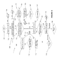
Figure 4 is a flow chart showing a foot-off diagnosis method in accordance with an embodiment of the present invention; -
Figure 5 is a plot of IMEP versus air mass flow showing the detection of a faulty pressure sensor; -
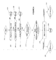
Figure 6 a flow chart showing a further diagnosis method in accordance with an embodiment of the present invention; -
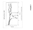
Figure 7 is a plot of IMEP versus time showing the effects of a misfiring cylinder; -
Figures 8 and 9 are general representations of an engine control unit suitable for use with the present invention and a flow chart representing the basic method according to the present invention. - In the following description and associated drawings like numerals are used to denote like features.
- The following terms may also be referenced in the following description and associated drawings: IMEP - Indicated Mean Effective Pressure, used in this development for engine torque control (Bar) (Indicated engine torque = IMEP x Engine swept volume (constant)); CA50% - Crank angle position at 50% of cumulative heat release rate (here referred to as the Centre of Combustion Position) (Degree Crank Angle); V - Cylinder volume (variable) (cm3); Q - Fuel mass or generated combustion heat; TDC - Top Dead Centre (
Reference 0 Crank angle); ECU Electronic Control unit. - In a compression-ignition internal combustion engine, such as a diesel engine, combustion takes place within one or more combustion chambers or cylinders, each chamber being defined partly by a reciprocating piston and partly by the walls of a cylinder bore formed in a cylinder head. The piston slides within the cylinder so that, when the engine is running, the volume of the combustion chamber cyclically increases and decreases. When the combustion chamber is at its minimum volume, the piston is said to be at 'Top Dead Centre' (TDC), and when the combustion chamber is at its maximum volume, the piston is said to be at 'Bottom Dead Centre' (BDC).
-
Figure 1 shows a representation of anengine system 1 described in the Applicant's co-pending European patent application08168714.7 engine system 1 comprises a plurality ofcylinders 2. In-cylinder pressure measurements from cylinder pressure sensors 3 are fed (arrow 5) into the vehicle'sengine control unit 7. The control method in accordance with the system described in the figure is generally represented by the "high level"algorithm box 9, the output of which areinjection control variables 11 which are sent to the engine'sinjectors 13. - Prior to the
sensor output 5 being used by thehigh level algorithm 9, a "low level"algorithm 15 cleans up the sensor data and calculates a number of combustion parameters which are then used by thehigh level algorithm 9. - In order to reduce the calculation load on the ECU and to enable the
engine model 9 to calculate injection control variables sufficiently quickly at all engine speeds the in-cylinder pressure measurements may conveniently be over-sampled. - Within the
low level algorithm 15 therefore the oversampled output of the sensors 3 is filtered by afiltering module 17 to produce a raw cylinder pressure array 19. The raw array 19 may then be passed to a scaling anddiagnostic module 21 which performs pressure measurement pegging and other scaling functions in order to output a corrected pressure array 23. It is noted that the applicant's patent applicationEP1936157 describes a pressure pegging method that may be utilised here. - The corrected pressure array 23 is then sent to a combustion
parameters calculation module 25 which calculates a number of combustion parameters as described below which may then be used by an engine model to control engine operation. - Parameters calculated in the
module 25 may comprise: the indicated mean effective pressure (IMEP) in bar (it is noted that the indicated engine torque = IMEP engine x swept volume (a constant)); CA50%, the cumulative heat release rate (HRR); peak pressure and location of peak pressure; the pressure derivative with respect to crank angle, DP/Dα, for combustion noise calculations (in particular the max DP/Dα and location of this maximum may be calculated). - The control method in accordance with the disclosure of
EP Application 08168714.7 algorithm box 9. The control method provides a mechanism for determining fuel quantities via atorque model 27 and for determining injection timings via a combustioncentre position model 29. Both models predict injection parameters with reference to one or more mathematical functions (as described below). In order to maintain the accuracy of thevarious engine models nonvolatile memory 31 of theECU 7. -
Figures 2 and3 illustrate the problem of sensor drift that is observed on cylinder pressure sensors after periods of in service use.Figure 2 shows a number of traces of cylinder pressure versus crank angle for an engine system in a cold idle state. It can be seen that the various pressure curves do not line up and this represents a drift in the sensor readings that develops after long periods of use. -
Figure 3 shows a similar trace for an engine system that is in a foot-off condition (i.e. a motoring condition). A portion of the figure has been enlarged and it can be seen that the sensor drift corresponds to an offset of a couple of degrees of crank angle at certain points on the pressure curve. - It is noted that the results shown in
Figures 2 and3 were derived from a test engine after durability testing. The same drift in the sensor output would also be experienced by in-service engines over time. -
Figure 4 is a flow chart showing a diagnosis algorithm in accordance with an embodiment of the present invention for use when an engine system is motoring (i.e. a "foot off" condition). - In
Step 100 the vehicle ECU initiates the diagnosis algorithm. This initiation could be in response to a driver or maintenance command or alternatively the algorithm could be run periodically. - In
Step 102, the ECU performs a check to see if the engine is in a foot-off condition (in other words that the engine is motoring and no fuel is being supplied to the injectors). If the engine is not motoring then the process stops inStep 104. - In
Step 106 the ECU checks to make sure that pressure and temperature conditions within the engine are suitable to run the diagnosis algorithm. This step essentially checks that the engine has been in a foot off condition for long enough to allow the diagnosis to run. If the pressure/temperature conditions are not met then the process stops inStep 108. - If the pressure/temperature conditions are met then the ECU may run one of three basic sub-processes, I, II or III. Process I is designed to diagnose sensor drift errors.
Process 11 can either diagnose sensor drift or blow-by errors. Process III can diagnose compression errors within the cylinders of the engine. - In process I, the ECU first checks in
Step 110 whether the output of the pressure sensors has been used to determine the true top dead centre position of the engine cylinders. If a "TDC learn" has not been performed then the process stops inStep 112. - If the TDC position of each cylinder is known then the process moves to step 114 in which the IMEP value for each cylinder is calculated from the pressure sensors. The IMEP value may be calculated by taking pressure values in the interval from 180° of crank angle before TDC to 180° of crank angle after TDC (i.e. the compression and power strokes). IMEP may then be calculated in accordance with the following equation:

where CAD= crank angle degree, V is the volume within the cylinder, P is the measured pressure value and IMEP hp is the indicated mean effective pressure of the high pressure cycle (i.e. compression to power stroke). - In
Step 116, the ECU determines if the calculated IMEP for each cylinder is within a pre-defined range. If all cylinders are within standard operating ranges then the process stops inStep 112. - If one or more cylinders shows an IMEP reading the is outside of the given range then the process returns a sensor drift error in
Step 118. - In process II, the ECU initially undertakes, in
Step 120, a measurement of the maximum cylinder pressure with respect to angular position for each cylinder. This is a statistical measurement performed over a number of engine cycles. This step determines the effective top dead centre position of each cylinder. - In
Step 122, the ECU checks to see if the measured TDC position inStep 120 has been compared to the expected TDC position for each cylinder (it is noted that the expected TDC position may be pre-loaded and stored on the ECU). If the offset from the expected TDC position has not yet been determined then, inStep 124, the ECU determines the offset between the measured and expected values. It is noted that due to heat losses the maximum pressure in a cylinder of a motoring engine is approximately 1 crank angle degree before the geometric top dead centre of the cylinder. The offset that is calculated by the ECU is therefore with respect to the thermodynamic TDC position (1° crank angle before geometric TDC). - If an initial offset between the measured and expected TDC positions has been calculated then the diagnosis process moves to Step 126 in which the difference from the previous offset calculation is determined for each cylinder.
- In
Step 128, the variation in the offset is assessed for each cylinder. If the variation is within pre-defined limits then the diagnosis process ends inStep 130. - If the offset variation for any cylinder is below a first threshold (e.g. if the TDC offset drops below 0.5 crank angle degrees from the initial learn TDC offset) then the ECU may determine that there is a blow-by error in the cylinder under evaluation (Step 132). If the offset variation is above the second threshold (e.g. if the TDC offset rises above 0.5 crank angle degrees from the initial learn TDC offset) then a sensor drift error is output (Step 118) for that cylinder.
- In process III the ECU initially, in
Step 134, determines the maximum pressure measurement for each cylinder and inStep 136 determines if the pressure values are within a pre-determined range. If the values are in range then the diagnosis process stops inStep 138. If the pressure value on any cylinder is outside of the pre-determined range then the diagnosis process returns a compression ratio error for the cylinder in question (Step 140). -
Figure 5 shows an example of cylinder pressure sensor drift that may be detected by the diagnosis method according to an embodiment of the present invention. The figure illustrates the results of the analysis of computed IMEP versus air mass flow in foot off driving conditions with coolant temperature in the range 0-80°C. It can be seen that three of the four cylinder sensors return IMEP readings within the valid, boxedregion 150. The sensor on cylinder 3 however is defective due to a wrongly measured IMEP (see circled area 152). -
Figure 6 illustrates the diagnosis process that may be performed during normal operating conditions (i.e. when the injectors are receiving and injecting fuel into the engine). - In
Step 200 the diagnosis process is started and inStep 202 the ECU checks that the engine is in a running mode. If no then the diagnostic process ends inStep 104. The ECU then checks, inStep 106, whether the vehicle is in a motoring (foot off condition). If the engine is motoring then the process terminates inStep 108. Finally, the ECU checks, inStep 110, whether the top dead centre position has been determined. If TDC has not been determined then the process terminates inStep 112. - In
Step 214, the pressure signals from the pressure sensors in each cylinder are used to measure the IMEP within each cylinder over time, i.e. over N cycles. In Step 216 a ratio of measured to estimated IMEP is calculated. It is therefore noted that inStep 216 an estimated IMEP value based on the current engine operating conditions is either calculated or received by theECU 7. It is noted that the Applicant's co-pending European patent application08168714.7 - In
Step 218 the ECU checks whether the ratio of measured to estimated IMEP is within a given range. If the ratio is less than a first threshold value (Step 220) then a misfiring fault is returned for the cylinder in question. If the ratio is determined to exceed a second threshold (Step 222) then an over fuelling fault is returned for the cylinder in question. If the ratio is within the predetermined allowable range then the diagnosis process terminates inStep 224. -
Figure 7 represents a misfiring error on a cylinder (IMEP variations in the bottom trace denote the effects of a misfire). -
Figures 8 and 9 are general representations of an engine control unit suitable for use with the present invention and a flow chart representing the basic method according to the present invention. - In
Figure 8 anECU 7 comprises monitoring means 300 and processing means 302. InFigure 9 , the method according to an embodiment of the present invention comprises monitoring 310 the output of in-cylinder pressure sensors, determining 312 a pressure related parameter and diagnosing 314 faults within the engine system. - It will be understood that the embodiments described above are given by way of example only and are not intended to limit the invention, the scope of which is defined in the appended claims. It will also be understood that the embodiments described may be used individually or in combination.
Claims (15)
- A method of diagnosing faults within an engine system (1), the engine system comprising a plurality of cylinders, the method comprising:monitoring (310) the output signal of one or more in-cylinder pressure sensors (3) within the engine system, each of the one or more in-cylinder pressure sensors being associated with a cylinder within the engine system;determining (312) a pressure related parameter for a given cylinder having an associated in-cylinder pressure sensor; anddiagnosing (314) the presence of faults within the engine system on the basis of the pressure related parameter.
- A method as claimed in Claim 1, wherein the determining step is performed when the engine system is in a motoring condition and the method optionally further comprises waiting (102) for a predetermined period of time after the engine system enters the motoring condition.
- A method as claimed in Claim 2, further comprising measuring the pressure and temperature within the engine cylinders until predefined testing conditions are satisfied.
- A method as claimed in Claim 1, wherein the pressure related parameter is the indicated mean effective pressure (IMEP) and wherein the determining step is performed when the engine system is in a motoring condition and the diagnosing step is arranged to diagnose a sensor drift error if the IMEP value for the given cylinder is outside a predetermined range.
- A method as claimed in Claim 1, wherein the pressure related parameter is the indicated mean effective pressure (IMEP) and wherein the diagnosing step (116, 118) comprises comparing determined IMEP values to IMEP values calculated from an engine model.
- A method as claimed in Claim 5, wherein the diagnosing step is arranged to diagnose an over-fuelling condition (122) on the given cylinder if the difference between determined and calculated IMEP values is above a threshold value and if the determined IMEP value is greater than the calculated IMEP value.
- A method as claimed in Claim 5, wherein the diagnosing step is arranged to diagnose a mis-fire condition (120) on the given cylinder if the difference between determined and calculated IMEP values is above a threshold value and if the calculated IMEP value is greater than the determined IMEP value.
- A method as claimed in Claim 1 to 4, wherein the pressure related parameter determined in the determining step is the top-dead-centre (TDC) position of the given cylinder and the diagnosing step (110, 122) comprises comparing the determined TDC position with predicted TDC position to derive a TDC offset value for the cylinder within the engine system.
- A method as claimed in Claim 8, wherein the diagnosing step is arranged to diagnose (132) a cylinder blow by condition if the TDC offset value exceeds a first threshold.
- A method as claimed in Claim 8, wherein the diagnosing step is arranged to diagnose a cylinder sensor drift condition (118) if the TDC offset value exceeds a second threshold.
- A method as claimed in Claim 1 to 4, wherein the pressure related parameter determined in the determining step is the maximum cylinder pressure per engine cycle and the diagnosing step is arranged to diagnose a compression ratio error condition (140) for the given cylinder if the determined maximum cylinder pressure falls outside a range of values about a reference cylinder pressure.
- A method as claimed in any preceding claim wherein each cylinder within the engine system is associated with an in-cylinder pressure sensor and the method comprises monitoring the output signal of each in-cylinder pressure sensor within the engine system, determining a pressure related parameter for each cylinder; and diagnosing the presence of faults within the engine system on the basis of the determined pressure related parameter, the method optionally further comprising outputting an error signal on the basis of the output from the diagnosing step.
- An ECU arranged to diagnose faults within an engine system, the engine system comprising a plurality of cylinders, the ECU comprising:monitoring means (300) arranged to monitor the output signal of one or more in-cylinder pressure sensors within the engine system, each of the one or more in-cylinder pressure sensors being associated with a cylinder within the engine system;processing means (302) arranged to determine a pressure related parameter for a given cylinder having an associated in-cylinder pressure sensor and arranged to diagnose the presence of faults within the engine system on the basis of the pressure related parameter.
- A computer readable medium comprising a computer program arranged to configure a computer or an electronic control unit to implement the method according to any one of Claims 1 to 12.
- A method of controlling an engine system comprising outputting the TDC offset value of Claim 8 to an engine model for use in engine control.
Priority Applications (6)
| Application Number | Priority Date | Filing Date | Title |
|---|---|---|---|
| EP10159322.6A EP2375038B1 (en) | 2010-04-08 | 2010-04-08 | Diagnosis device and method using an in-cylinder pressure sensor in an internal combustion engine |
| PCT/EP2011/055506 WO2011124680A1 (en) | 2010-04-08 | 2011-04-08 | Diagnosis devise and method using an in- cylinder pressure sensor in an internal combustion engine |
| KR1020127029238A KR20130006505A (en) | 2010-04-08 | 2011-04-08 | Diagnosis devise and method using an in- cylinder pressure sensor in an internal combustion engine |
| US13/639,216 US20130060447A1 (en) | 2010-04-08 | 2011-04-08 | Vehicle diagnosis device and method |
| CN201180018156.7A CN102893000B (en) | 2010-04-08 | 2011-04-08 | Diagnosis apparatus and the method for in-cylinder pressure sensor is used in explosive motor |
| EP11714521.9A EP2556231B1 (en) | 2010-04-08 | 2011-04-08 | Diagnosis device and method using an in-cylinder pressure sensor in an internal combustion engine |
Applications Claiming Priority (1)
| Application Number | Priority Date | Filing Date | Title |
|---|---|---|---|
| EP10159322.6A EP2375038B1 (en) | 2010-04-08 | 2010-04-08 | Diagnosis device and method using an in-cylinder pressure sensor in an internal combustion engine |
Publications (2)
| Publication Number | Publication Date |
|---|---|
| EP2375038A1 true EP2375038A1 (en) | 2011-10-12 |
| EP2375038B1 EP2375038B1 (en) | 2015-03-04 |
Family
ID=42537806
Family Applications (2)
| Application Number | Title | Priority Date | Filing Date |
|---|---|---|---|
| EP10159322.6A Active EP2375038B1 (en) | 2010-04-08 | 2010-04-08 | Diagnosis device and method using an in-cylinder pressure sensor in an internal combustion engine |
| EP11714521.9A Active EP2556231B1 (en) | 2010-04-08 | 2011-04-08 | Diagnosis device and method using an in-cylinder pressure sensor in an internal combustion engine |
Family Applications After (1)
| Application Number | Title | Priority Date | Filing Date |
|---|---|---|---|
| EP11714521.9A Active EP2556231B1 (en) | 2010-04-08 | 2011-04-08 | Diagnosis device and method using an in-cylinder pressure sensor in an internal combustion engine |
Country Status (5)
| Country | Link |
|---|---|
| US (1) | US20130060447A1 (en) |
| EP (2) | EP2375038B1 (en) |
| KR (1) | KR20130006505A (en) |
| CN (1) | CN102893000B (en) |
| WO (1) | WO2011124680A1 (en) |
Cited By (6)
| Publication number | Priority date | Publication date | Assignee | Title |
|---|---|---|---|---|
| CN103940554A (en) * | 2013-01-22 | 2014-07-23 | 上海汽车集团股份有限公司 | Engine fault diagnosis method and equipment |
| EP2778379A4 (en) * | 2011-11-11 | 2015-08-05 | Toyota Motor Co Ltd | PRESSURE SENSOR DIAGNOSTIC DEVICE MOUNTED IN THE CYLINDER, AND SENSOR SENSITIVITY CORRECTION DEVICE MOUNTED IN THE CYLINDER, EQUIPPED WITH SAME |
| EP3617485A1 (en) * | 2018-09-03 | 2020-03-04 | Mazda Motor Corporation | Failure diagnosis device, engine, failure diagnosis method, and computer program product |
| EP3617489A1 (en) * | 2018-09-03 | 2020-03-04 | Mazda Motor Corporation | Failure diagnosis device, engine, failure diagnosis method, and computer program product |
| EP3617486A1 (en) * | 2018-09-03 | 2020-03-04 | Mazda Motor Corporation | Failure diagnosis device, engine, failure diagnosis method, and computer program product |
| US11802519B1 (en) | 2022-11-15 | 2023-10-31 | Cummins Inc. | Systems and methods for bypassing a compromised engine cylinder via cylinder deactivation |
Families Citing this family (16)
| Publication number | Priority date | Publication date | Assignee | Title |
|---|---|---|---|---|
| KR101352369B1 (en) | 2011-12-20 | 2014-01-17 | 한국기계연구원 | System for Automation of Hydraulic Motor Performance Test |
| KR101458197B1 (en) * | 2013-02-25 | 2014-11-04 | 호남대학교 산학협력단 | Engine cylinder pressure monitoring device |
| JP2015018505A (en) * | 2013-07-12 | 2015-01-29 | 株式会社東芝 | Failure prediction apparatus |
| US20160160776A1 (en) * | 2014-12-08 | 2016-06-09 | Caterpillar Inc. | Engine System and Method |
| US9752949B2 (en) | 2014-12-31 | 2017-09-05 | General Electric Company | System and method for locating engine noise |
| DE102015203637A1 (en) * | 2015-03-02 | 2016-09-08 | Robert Bosch Gmbh | Method and device for determining a signal offset between a crankshaft angle signal and a combustion chamber pressure signal in an internal combustion engine |
| KR102021249B1 (en) * | 2015-09-11 | 2019-09-11 | 바르실라 핀랜드 오이 | Method and control system for determining offsets regarding crank angle measurement |
| EP3239684A1 (en) | 2016-04-29 | 2017-11-01 | Siemens Aktiengesellschaft | Fault diagnosis during testing of turbine unit |
| AT518864B1 (en) * | 2016-08-09 | 2018-02-15 | Avl List Gmbh | METHOD FOR ASSESSING THE CONDITION OF AN INTERNAL COMBUSTION ENGINE |
| KR102180789B1 (en) * | 2016-08-18 | 2020-11-19 | 한국조선해양 주식회사 | Apparatus and method for monitoring engine condition |
| US10760543B2 (en) | 2017-07-12 | 2020-09-01 | Innio Jenbacher Gmbh & Co Og | System and method for valve event detection and control |
| US10570833B2 (en) * | 2017-11-06 | 2020-02-25 | Caterpillar Inc. | System and method for predicting failure of a cylinder in a multi-cylinder engine |
| JP2019157696A (en) * | 2018-03-09 | 2019-09-19 | 本田技研工業株式会社 | Control device for internal combustion engine |
| DE102018211783B4 (en) * | 2018-07-16 | 2021-02-11 | Robert Bosch Gmbh | Method and device for controlling an internal combustion engine |
| CN114459762B (en) * | 2020-12-25 | 2024-02-23 | 北京天兵科技有限公司 | Rocket engine health state diagnosis system and method |
| CN116641793B (en) * | 2023-06-08 | 2025-10-28 | 长城汽车股份有限公司 | Engine abnormality detection method, device, vehicle and storage medium |
Citations (8)
| Publication number | Priority date | Publication date | Assignee | Title |
|---|---|---|---|---|
| GB2192028A (en) * | 1986-06-28 | 1987-12-31 | Honda Motor Co Ltd | Method of and apparatus for detecting maximum cylinder pressure angle in an internal combustion engine |
| EP0657729A2 (en) * | 1993-12-09 | 1995-06-14 | Unisia Jecs Corporation | Self-diagnosing apparatus and method for determining occurrence of failure in inner cylinder pressure responsive sensor appliccable to engine combustion detecting/controlling system |
| US5554801A (en) * | 1994-06-14 | 1996-09-10 | Unisia Jecs Corporation | Diagnosis apparatus and method for a cylinder pressure sensor |
| US5648602A (en) * | 1993-12-13 | 1997-07-15 | Unisia Jecs Corporation | Internal combustion engine misfire detection apparatus |
| WO2002095191A2 (en) * | 2001-05-21 | 2002-11-28 | Ricardo Consulting Engineers Limited | Improved engine management |
| WO2002101220A1 (en) * | 2001-06-13 | 2002-12-19 | Abb Ab | Method to determine tdc in an internal combustion engine |
| DE102004048330A1 (en) * | 2004-10-05 | 2006-04-06 | Volkswagen Ag | Method for diagnosis for a motor control and corresponding motor control |
| EP1936157A2 (en) | 2006-12-20 | 2008-06-25 | Delphi Technologies, Inc. | Combustion control in an internal combustion engine |
Family Cites Families (33)
| Publication number | Priority date | Publication date | Assignee | Title |
|---|---|---|---|---|
| US4633707A (en) * | 1982-09-13 | 1987-01-06 | Jodon Engineering Associates, Inc. | Method and apparatus for measuring engine compression ratio, clearance volume and related cylinder parameters |
| JPS62192627A (en) * | 1986-02-19 | 1987-08-24 | Honda Motor Co Ltd | How to correct the cylinder pressure of an internal combustion engine |
| US4718382A (en) * | 1986-02-19 | 1988-01-12 | Honda Giken Kogyo Kabushiki Kaisha | Device for controlling ignition timing in internal combustion engine |
| US5076098A (en) * | 1990-02-21 | 1991-12-31 | Nissan Motor Company, Limited | System for detecting combustion state in internal combustion engine |
| JP2611502B2 (en) * | 1990-06-13 | 1997-05-21 | 三菱電機株式会社 | Misfire detection device for internal combustion engine |
| KR940002066B1 (en) * | 1990-08-24 | 1994-03-16 | 미쯔비시 덴끼 가부시기가이샤 | Failure, detecting method for pressure sensor |
| DE59201787D1 (en) * | 1991-01-24 | 1995-05-04 | Siemens Ag | DEVICE FOR DETECTING DEFECTIVE BURNS IN AN INTERNAL COMBUSTION ENGINE. |
| JP2855923B2 (en) * | 1991-11-06 | 1999-02-10 | 三菱電機株式会社 | Engine control device and engine control method |
| JP2829698B2 (en) * | 1993-10-19 | 1998-11-25 | 株式会社ユニシアジェックス | Device for detecting combustion state of internal combustion engine |
| JPH07301145A (en) * | 1994-05-09 | 1995-11-14 | Unisia Jecs Corp | Failure diagnosis device for cylinder pressure sensor of internal combustion engine |
| JPH0828338A (en) * | 1994-07-11 | 1996-01-30 | Unisia Jecs Corp | Crank angle position detection device and control device for internal combustion engine |
| JPH08246941A (en) * | 1995-03-10 | 1996-09-24 | Unisia Jecs Corp | Failure diagnosis device for cylinder pressure sensor of internal combustion engine |
| US5786531A (en) * | 1997-02-27 | 1998-07-28 | General Motors Corporation | Compression ratio measurement |
| DE19927846C2 (en) * | 1999-06-18 | 2001-09-13 | Mtu Friedrichshafen Gmbh | Method for monitoring an internal combustion engine |
| US6516781B2 (en) * | 2000-12-05 | 2003-02-11 | Detroit Diesel Corporation | Method and system for enhanced engine control based on cylinder pressure |
| US6484694B2 (en) * | 2000-12-05 | 2002-11-26 | Detroit Diesel Corporation | Method of controlling an internal combustion engine |
| EP2479412A3 (en) * | 2001-03-30 | 2014-08-13 | Mitsubishi Heavy Industries, Ltd. | Apparatus and method of combustion diagnosis/control in internal combustion engine |
| JP2002332908A (en) * | 2001-05-02 | 2002-11-22 | Ngk Spark Plug Co Ltd | Internal combustion engine misfire detection method and misfire detection system |
| DE10240492A1 (en) * | 2002-09-03 | 2004-03-11 | Robert Bosch Gmbh | Method for calibrating the cylinder sensors of an internal combustion engine operated individually for a cylinder, in particular a motor vehicle |
| GB0227672D0 (en) * | 2002-11-27 | 2003-01-08 | Ricardo Consulting Eng | Improved engine management |
| FR2865771B1 (en) * | 2004-02-02 | 2007-11-09 | Peugeot Citroen Automobiles Sa | METHOD FOR DIAGNOSING THE OPERATING STATE OF A DIESEL ENGINE FOR A MOTOR VEHICLE |
| JP4354334B2 (en) * | 2004-05-20 | 2009-10-28 | 本田技研工業株式会社 | Device for determining failure of in-cylinder pressure sensor |
| DE102004048319B4 (en) * | 2004-10-05 | 2006-07-27 | Robert Bosch Gmbh | Method and device for determining control times for gas exchange valves of an internal combustion engine |
| DE102005039757A1 (en) * | 2005-08-23 | 2007-03-01 | Robert Bosch Gmbh | Diesel-internal combustion engine operating method, involves determining drift of impact sound sensors from temporal change of value compared to another value, where values depend on pressure distribution in one of combustion chambers |
| US7726281B2 (en) * | 2006-05-11 | 2010-06-01 | Gm Global Technology Operations, Inc. | Cylinder pressure sensor diagnostic system and method |
| JP4276241B2 (en) * | 2006-05-11 | 2009-06-10 | 株式会社日立製作所 | Engine control device |
| JP4552898B2 (en) * | 2006-05-30 | 2010-09-29 | 株式会社デンソー | In-cylinder pressure sensor abnormality determination device |
| US7568467B2 (en) * | 2007-03-23 | 2009-08-04 | Gm Global Technology Operations, Inc. | Crank position correction using cylinder pressure |
| US7469576B2 (en) * | 2007-04-05 | 2008-12-30 | Delphi Technologies, Inc. | Method and apparatus for determining TDC for each cylinder of a multi-cylinder internal combustion engine |
| DE102007057142A1 (en) * | 2007-11-28 | 2009-06-04 | Robert Bosch Gmbh | Direct injection internal combustion engine e.g. petrol-internal combustion engine, operating method for motor vehicle, involves determining maximum pressure by considering values characterizing pressure loss, and examining sensor |
| DE102008006569B4 (en) * | 2008-01-29 | 2024-03-21 | Robert Bosch Gmbh | Device and method for detecting a leak in a cylinder of an internal combustion engine |
| US7680583B2 (en) * | 2008-04-11 | 2010-03-16 | Delphi Technologies, Inc. | Method for low and high IMEP cylinder identification for cylinder balancing |
| US7623955B1 (en) * | 2008-04-30 | 2009-11-24 | Delphi Technologies, Inc. | Method for estimation of indicated mean effective pressure for individual cylinders from crankshaft acceleration |
-
2010
- 2010-04-08 EP EP10159322.6A patent/EP2375038B1/en active Active
-
2011
- 2011-04-08 KR KR1020127029238A patent/KR20130006505A/en not_active Ceased
- 2011-04-08 US US13/639,216 patent/US20130060447A1/en not_active Abandoned
- 2011-04-08 CN CN201180018156.7A patent/CN102893000B/en active Active
- 2011-04-08 EP EP11714521.9A patent/EP2556231B1/en active Active
- 2011-04-08 WO PCT/EP2011/055506 patent/WO2011124680A1/en not_active Ceased
Patent Citations (8)
| Publication number | Priority date | Publication date | Assignee | Title |
|---|---|---|---|---|
| GB2192028A (en) * | 1986-06-28 | 1987-12-31 | Honda Motor Co Ltd | Method of and apparatus for detecting maximum cylinder pressure angle in an internal combustion engine |
| EP0657729A2 (en) * | 1993-12-09 | 1995-06-14 | Unisia Jecs Corporation | Self-diagnosing apparatus and method for determining occurrence of failure in inner cylinder pressure responsive sensor appliccable to engine combustion detecting/controlling system |
| US5648602A (en) * | 1993-12-13 | 1997-07-15 | Unisia Jecs Corporation | Internal combustion engine misfire detection apparatus |
| US5554801A (en) * | 1994-06-14 | 1996-09-10 | Unisia Jecs Corporation | Diagnosis apparatus and method for a cylinder pressure sensor |
| WO2002095191A2 (en) * | 2001-05-21 | 2002-11-28 | Ricardo Consulting Engineers Limited | Improved engine management |
| WO2002101220A1 (en) * | 2001-06-13 | 2002-12-19 | Abb Ab | Method to determine tdc in an internal combustion engine |
| DE102004048330A1 (en) * | 2004-10-05 | 2006-04-06 | Volkswagen Ag | Method for diagnosis for a motor control and corresponding motor control |
| EP1936157A2 (en) | 2006-12-20 | 2008-06-25 | Delphi Technologies, Inc. | Combustion control in an internal combustion engine |
Non-Patent Citations (2)
| Title |
|---|
| HOUNTALAS D T ET AL: "Experimental investigation to develop a methodology for estimating the compression condition of DI Diesel engines", ENERGY CONVERSION AND MANAGEMENT, ELSEVIER SCIENCE PUBLISHERS, OXFORD, GB, vol. 47, no. 1, 1 January 2006 (2006-01-01), pages 1 - 18, XP025067033, ISSN: 0196-8904, [retrieved on 20060101], DOI: 10.1016/J.ENCONMAN.2005.04.001 * |
| YLVA NILSSON ET AL: "Determining Tdc Position Using Symmetry and Other Methods", 1 March 2004, MODELLING OF SPARK IGNITION ENGINES, SAE INTERNATIONAL, US, PAGE(S) 247 - 256, ISBN: 978-0-7680-1366-5, XP008097935 * |
Cited By (14)
| Publication number | Priority date | Publication date | Assignee | Title |
|---|---|---|---|---|
| EP2778379A4 (en) * | 2011-11-11 | 2015-08-05 | Toyota Motor Co Ltd | PRESSURE SENSOR DIAGNOSTIC DEVICE MOUNTED IN THE CYLINDER, AND SENSOR SENSITIVITY CORRECTION DEVICE MOUNTED IN THE CYLINDER, EQUIPPED WITH SAME |
| US9435707B2 (en) | 2011-11-11 | 2016-09-06 | Toyota Jidosha Kabushiki Kaisha | Intra-cylinder pressure sensor fault diagnostic device and intra-cylinder sensor sensitivity correction device provided with same |
| CN103940554A (en) * | 2013-01-22 | 2014-07-23 | 上海汽车集团股份有限公司 | Engine fault diagnosis method and equipment |
| CN103940554B (en) * | 2013-01-22 | 2016-06-22 | 上海汽车集团股份有限公司 | Fault Diagnosis of Engine and equipment |
| EP3617486A1 (en) * | 2018-09-03 | 2020-03-04 | Mazda Motor Corporation | Failure diagnosis device, engine, failure diagnosis method, and computer program product |
| EP3617489A1 (en) * | 2018-09-03 | 2020-03-04 | Mazda Motor Corporation | Failure diagnosis device, engine, failure diagnosis method, and computer program product |
| EP3617485A1 (en) * | 2018-09-03 | 2020-03-04 | Mazda Motor Corporation | Failure diagnosis device, engine, failure diagnosis method, and computer program product |
| CN110873001A (en) * | 2018-09-03 | 2020-03-10 | 马自达汽车株式会社 | Fault diagnosis device for cylinder pressure sensor |
| CN110872984A (en) * | 2018-09-03 | 2020-03-10 | 马自达汽车株式会社 | Fault diagnosis device for cylinder pressure sensor |
| CN110872999A (en) * | 2018-09-03 | 2020-03-10 | 马自达汽车株式会社 | Fault diagnosis device for cylinder pressure sensor |
| US10815917B2 (en) | 2018-09-03 | 2020-10-27 | Mazda Motor Corporation | Failure diagnosis device for in-cylinder pressure sensor |
| US10876488B2 (en) | 2018-09-03 | 2020-12-29 | Mazda Motor Corporation | Failure diagnosis device for in-cylinder pressure sensor |
| CN110872984B (en) * | 2018-09-03 | 2021-10-08 | 马自达汽车株式会社 | Fault diagnosis device for cylinder pressure sensor |
| US11802519B1 (en) | 2022-11-15 | 2023-10-31 | Cummins Inc. | Systems and methods for bypassing a compromised engine cylinder via cylinder deactivation |
Also Published As
| Publication number | Publication date |
|---|---|
| CN102893000B (en) | 2016-01-27 |
| WO2011124680A1 (en) | 2011-10-13 |
| US20130060447A1 (en) | 2013-03-07 |
| EP2556231B1 (en) | 2019-12-25 |
| CN102893000A (en) | 2013-01-23 |
| KR20130006505A (en) | 2013-01-16 |
| EP2375038B1 (en) | 2015-03-04 |
| EP2556231A1 (en) | 2013-02-13 |
Similar Documents
| Publication | Publication Date | Title |
|---|---|---|
| EP2375038B1 (en) | Diagnosis device and method using an in-cylinder pressure sensor in an internal combustion engine | |
| EP1402165B1 (en) | Method to determine tdc in an internal combustion engine | |
| US8046155B2 (en) | Method and apparatus for misfire detection using engine cycles at least subsequent to actual misfire event | |
| US8200415B2 (en) | Method and device for controlling the operating mode of an internal combustion engine | |
| US20080228341A1 (en) | Vehicle diagnosis system and method | |
| WO2009155132A2 (en) | Fuel system diagnostics by analyzing engine cylinder pressure signal and crankshaft speed signal | |
| WO2009129075A1 (en) | Fuel system diagnostics by analyzing cylinder pressure signal | |
| BG63832B1 (en) | Process for detecting a misfire in an internal combustion engine and system for carrying out said process | |
| CN101957266A (en) | The detection of catching fire by combustion pressure sensor | |
| KR100959214B1 (en) | Misfire detection device of internal combustion engine | |
| Corti et al. | Transient spark advance calibration approach | |
| WO2009048519A2 (en) | Robust onboard diagnostic misfire detection | |
| US11226264B2 (en) | Method for the diagnosis of engine misfires in an internal combustion engine | |
| US7920957B2 (en) | Method and control device for metering fuel to combustion chambers of an internal combustion engine | |
| KR20130025397A (en) | Injection control method | |
| US6801848B1 (en) | Methods and apparatus for sensing misfire in an internal combustion engine | |
| EP1972769B1 (en) | Internal combustion engine fuel delivery system diagnosis device and method | |
| CN101389843B (en) | Engine control device and method for determining pressure in a combustion chamber of an internal combustion engine | |
| WO2008140404A1 (en) | Method and computer program product for identifying a malfunctioning cylinder of a multi-cylinder combustion engine | |
| CN111094715B (en) | Method for analyzing the operation of a decontamination system of a motor vehicle | |
| JP5880187B2 (en) | Fuel injection valve inspection device | |
| CN106609708A (en) | Pre-chamber fuel admission valve diagnostics | |
| EP1731890A1 (en) | Method and apparatus for calibrating the gain of a cylinder pressure sensor of an internal combustion engine | |
| US20220178325A1 (en) | Camshaft phase error monitoring | |
| RU2445597C2 (en) | Evaluation method of technical state of internal combustion engine |
Legal Events
| Date | Code | Title | Description |
|---|---|---|---|
| PUAI | Public reference made under article 153(3) epc to a published international application that has entered the european phase |
Free format text: ORIGINAL CODE: 0009012 |
|
| AK | Designated contracting states |
Kind code of ref document: A1 Designated state(s): AT BE BG CH CY CZ DE DK EE ES FI FR GB GR HR HU IE IS IT LI LT LU LV MC MK MT NL NO PL PT RO SE SI SK SM TR |
|
| AX | Request for extension of the european patent |
Extension state: AL BA ME RS |
|
| 17P | Request for examination filed |
Effective date: 20120412 |
|
| 17Q | First examination report despatched |
Effective date: 20130408 |
|
| REG | Reference to a national code |
Ref country code: DE Ref legal event code: R079 Ref document number: 602010022751 Country of ref document: DE Free format text: PREVIOUS MAIN CLASS: F02D0041220000 Ipc: F02D0035020000 |
|
| RIC1 | Information provided on ipc code assigned before grant |
Ipc: F02D 41/22 20060101ALI20131212BHEP Ipc: F02D 35/02 20060101AFI20131212BHEP |
|
| RAP1 | Party data changed (applicant data changed or rights of an application transferred) |
Owner name: DELPHI INTERNATIONAL OPERATIONS LUXEMBOURG S.A.R.L |
|
| GRAP | Despatch of communication of intention to grant a patent |
Free format text: ORIGINAL CODE: EPIDOSNIGR1 |
|
| INTG | Intention to grant announced |
Effective date: 20141008 |
|
| GRAS | Grant fee paid |
Free format text: ORIGINAL CODE: EPIDOSNIGR3 |
|
| GRAA | (expected) grant |
Free format text: ORIGINAL CODE: 0009210 |
|
| AK | Designated contracting states |
Kind code of ref document: B1 Designated state(s): AT BE BG CH CY CZ DE DK EE ES FI FR GB GR HR HU IE IS IT LI LT LU LV MC MK MT NL NO PL PT RO SE SI SK SM TR |
|
| AX | Request for extension of the european patent |
Extension state: AL BA ME RS |
|
| REG | Reference to a national code |
Ref country code: GB Ref legal event code: FG4D |
|
| REG | Reference to a national code |
Ref country code: CH Ref legal event code: EP |
|
| REG | Reference to a national code |
Ref country code: IE Ref legal event code: FG4D |
|
| REG | Reference to a national code |
Ref country code: AT Ref legal event code: REF Ref document number: 714112 Country of ref document: AT Kind code of ref document: T Effective date: 20150415 |
|
| REG | Reference to a national code |
Ref country code: DE Ref legal event code: R096 Ref document number: 602010022751 Country of ref document: DE Effective date: 20150416 |
|
| REG | Reference to a national code |
Ref country code: FR Ref legal event code: PLFP Year of fee payment: 6 |
|
| REG | Reference to a national code |
Ref country code: AT Ref legal event code: MK05 Ref document number: 714112 Country of ref document: AT Kind code of ref document: T Effective date: 20150304 Ref country code: NL Ref legal event code: VDEP Effective date: 20150304 |
|
| PG25 | Lapsed in a contracting state [announced via postgrant information from national office to epo] |
Ref country code: NO Free format text: LAPSE BECAUSE OF FAILURE TO SUBMIT A TRANSLATION OF THE DESCRIPTION OR TO PAY THE FEE WITHIN THE PRESCRIBED TIME-LIMIT Effective date: 20150604 Ref country code: FI Free format text: LAPSE BECAUSE OF FAILURE TO SUBMIT A TRANSLATION OF THE DESCRIPTION OR TO PAY THE FEE WITHIN THE PRESCRIBED TIME-LIMIT Effective date: 20150304 Ref country code: SE Free format text: LAPSE BECAUSE OF FAILURE TO SUBMIT A TRANSLATION OF THE DESCRIPTION OR TO PAY THE FEE WITHIN THE PRESCRIBED TIME-LIMIT Effective date: 20150304 Ref country code: HR Free format text: LAPSE BECAUSE OF FAILURE TO SUBMIT A TRANSLATION OF THE DESCRIPTION OR TO PAY THE FEE WITHIN THE PRESCRIBED TIME-LIMIT Effective date: 20150304 Ref country code: LT Free format text: LAPSE BECAUSE OF FAILURE TO SUBMIT A TRANSLATION OF THE DESCRIPTION OR TO PAY THE FEE WITHIN THE PRESCRIBED TIME-LIMIT Effective date: 20150304 Ref country code: ES Free format text: LAPSE BECAUSE OF FAILURE TO SUBMIT A TRANSLATION OF THE DESCRIPTION OR TO PAY THE FEE WITHIN THE PRESCRIBED TIME-LIMIT Effective date: 20150304 |
|
| REG | Reference to a national code |
Ref country code: LT Ref legal event code: MG4D |
|
| PG25 | Lapsed in a contracting state [announced via postgrant information from national office to epo] |
Ref country code: GR Free format text: LAPSE BECAUSE OF FAILURE TO SUBMIT A TRANSLATION OF THE DESCRIPTION OR TO PAY THE FEE WITHIN THE PRESCRIBED TIME-LIMIT Effective date: 20150605 Ref country code: LV Free format text: LAPSE BECAUSE OF FAILURE TO SUBMIT A TRANSLATION OF THE DESCRIPTION OR TO PAY THE FEE WITHIN THE PRESCRIBED TIME-LIMIT Effective date: 20150304 Ref country code: AT Free format text: LAPSE BECAUSE OF FAILURE TO SUBMIT A TRANSLATION OF THE DESCRIPTION OR TO PAY THE FEE WITHIN THE PRESCRIBED TIME-LIMIT Effective date: 20150304 |
|
| PG25 | Lapsed in a contracting state [announced via postgrant information from national office to epo] |
Ref country code: NL Free format text: LAPSE BECAUSE OF FAILURE TO SUBMIT A TRANSLATION OF THE DESCRIPTION OR TO PAY THE FEE WITHIN THE PRESCRIBED TIME-LIMIT Effective date: 20150304 |
|
| PG25 | Lapsed in a contracting state [announced via postgrant information from national office to epo] |
Ref country code: RO Free format text: LAPSE BECAUSE OF FAILURE TO SUBMIT A TRANSLATION OF THE DESCRIPTION OR TO PAY THE FEE WITHIN THE PRESCRIBED TIME-LIMIT Effective date: 20150304 Ref country code: CZ Free format text: LAPSE BECAUSE OF FAILURE TO SUBMIT A TRANSLATION OF THE DESCRIPTION OR TO PAY THE FEE WITHIN THE PRESCRIBED TIME-LIMIT Effective date: 20150304 Ref country code: SK Free format text: LAPSE BECAUSE OF FAILURE TO SUBMIT A TRANSLATION OF THE DESCRIPTION OR TO PAY THE FEE WITHIN THE PRESCRIBED TIME-LIMIT Effective date: 20150304 Ref country code: PT Free format text: LAPSE BECAUSE OF FAILURE TO SUBMIT A TRANSLATION OF THE DESCRIPTION OR TO PAY THE FEE WITHIN THE PRESCRIBED TIME-LIMIT Effective date: 20150706 Ref country code: EE Free format text: LAPSE BECAUSE OF FAILURE TO SUBMIT A TRANSLATION OF THE DESCRIPTION OR TO PAY THE FEE WITHIN THE PRESCRIBED TIME-LIMIT Effective date: 20150304 |
|
| PG25 | Lapsed in a contracting state [announced via postgrant information from national office to epo] |
Ref country code: PL Free format text: LAPSE BECAUSE OF FAILURE TO SUBMIT A TRANSLATION OF THE DESCRIPTION OR TO PAY THE FEE WITHIN THE PRESCRIBED TIME-LIMIT Effective date: 20150304 Ref country code: IS Free format text: LAPSE BECAUSE OF FAILURE TO SUBMIT A TRANSLATION OF THE DESCRIPTION OR TO PAY THE FEE WITHIN THE PRESCRIBED TIME-LIMIT Effective date: 20150704 Ref country code: MC Free format text: LAPSE BECAUSE OF FAILURE TO SUBMIT A TRANSLATION OF THE DESCRIPTION OR TO PAY THE FEE WITHIN THE PRESCRIBED TIME-LIMIT Effective date: 20150304 |
|
| REG | Reference to a national code |
Ref country code: HU Ref legal event code: AG4A Ref document number: E024308 Country of ref document: HU Ref country code: CH Ref legal event code: PL |
|
| REG | Reference to a national code |
Ref country code: DE Ref legal event code: R097 Ref document number: 602010022751 Country of ref document: DE |
|
| PLBE | No opposition filed within time limit |
Free format text: ORIGINAL CODE: 0009261 |
|
| STAA | Information on the status of an ep patent application or granted ep patent |
Free format text: STATUS: NO OPPOSITION FILED WITHIN TIME LIMIT |
|
| REG | Reference to a national code |
Ref country code: IE Ref legal event code: MM4A |
|
| PG25 | Lapsed in a contracting state [announced via postgrant information from national office to epo] |
Ref country code: DK Free format text: LAPSE BECAUSE OF FAILURE TO SUBMIT A TRANSLATION OF THE DESCRIPTION OR TO PAY THE FEE WITHIN THE PRESCRIBED TIME-LIMIT Effective date: 20150304 Ref country code: LI Free format text: LAPSE BECAUSE OF NON-PAYMENT OF DUE FEES Effective date: 20150430 Ref country code: CH Free format text: LAPSE BECAUSE OF NON-PAYMENT OF DUE FEES Effective date: 20150430 |
|
| 26N | No opposition filed |
Effective date: 20151207 |
|
| GBPC | Gb: european patent ceased through non-payment of renewal fee |
Effective date: 20150604 |
|
| PG25 | Lapsed in a contracting state [announced via postgrant information from national office to epo] |
Ref country code: SI Free format text: LAPSE BECAUSE OF FAILURE TO SUBMIT A TRANSLATION OF THE DESCRIPTION OR TO PAY THE FEE WITHIN THE PRESCRIBED TIME-LIMIT Effective date: 20150304 |
|
| REG | Reference to a national code |
Ref country code: FR Ref legal event code: PLFP Year of fee payment: 7 |
|
| PG25 | Lapsed in a contracting state [announced via postgrant information from national office to epo] |
Ref country code: GB Free format text: LAPSE BECAUSE OF NON-PAYMENT OF DUE FEES Effective date: 20150604 Ref country code: IE Free format text: LAPSE BECAUSE OF NON-PAYMENT OF DUE FEES Effective date: 20150408 |
|
| PG25 | Lapsed in a contracting state [announced via postgrant information from national office to epo] |
Ref country code: BE Free format text: LAPSE BECAUSE OF FAILURE TO SUBMIT A TRANSLATION OF THE DESCRIPTION OR TO PAY THE FEE WITHIN THE PRESCRIBED TIME-LIMIT Effective date: 20150304 |
|
| PG25 | Lapsed in a contracting state [announced via postgrant information from national office to epo] |
Ref country code: MT Free format text: LAPSE BECAUSE OF FAILURE TO SUBMIT A TRANSLATION OF THE DESCRIPTION OR TO PAY THE FEE WITHIN THE PRESCRIBED TIME-LIMIT Effective date: 20150304 |
|
| REG | Reference to a national code |
Ref country code: FR Ref legal event code: PLFP Year of fee payment: 8 |
|
| PG25 | Lapsed in a contracting state [announced via postgrant information from national office to epo] |
Ref country code: BG Free format text: LAPSE BECAUSE OF FAILURE TO SUBMIT A TRANSLATION OF THE DESCRIPTION OR TO PAY THE FEE WITHIN THE PRESCRIBED TIME-LIMIT Effective date: 20150304 Ref country code: SM Free format text: LAPSE BECAUSE OF FAILURE TO SUBMIT A TRANSLATION OF THE DESCRIPTION OR TO PAY THE FEE WITHIN THE PRESCRIBED TIME-LIMIT Effective date: 20150304 |
|
| PG25 | Lapsed in a contracting state [announced via postgrant information from national office to epo] |
Ref country code: CY Free format text: LAPSE BECAUSE OF FAILURE TO SUBMIT A TRANSLATION OF THE DESCRIPTION OR TO PAY THE FEE WITHIN THE PRESCRIBED TIME-LIMIT Effective date: 20150304 |
|
| PG25 | Lapsed in a contracting state [announced via postgrant information from national office to epo] |
Ref country code: TR Free format text: LAPSE BECAUSE OF FAILURE TO SUBMIT A TRANSLATION OF THE DESCRIPTION OR TO PAY THE FEE WITHIN THE PRESCRIBED TIME-LIMIT Effective date: 20150304 |
|
| PG25 | Lapsed in a contracting state [announced via postgrant information from national office to epo] |
Ref country code: LU Free format text: LAPSE BECAUSE OF NON-PAYMENT OF DUE FEES Effective date: 20150408 |
|
| REG | Reference to a national code |
Ref country code: FR Ref legal event code: PLFP Year of fee payment: 9 |
|
| PG25 | Lapsed in a contracting state [announced via postgrant information from national office to epo] |
Ref country code: MK Free format text: LAPSE BECAUSE OF FAILURE TO SUBMIT A TRANSLATION OF THE DESCRIPTION OR TO PAY THE FEE WITHIN THE PRESCRIBED TIME-LIMIT Effective date: 20150304 |
|
| REG | Reference to a national code |
Ref country code: DE Ref legal event code: R081 Ref document number: 602010022751 Country of ref document: DE Owner name: DELPHI AUTOMOTIVE SYSTEMS LUXEMBOURG S.A., LU Free format text: FORMER OWNER: DELPHI INTERNATIONAL OPERATIONS LUXEMBOURG S.A R.L., BASCHARAGE, LU |
|
| PGFP | Annual fee paid to national office [announced via postgrant information from national office to epo] |
Ref country code: FR Payment date: 20200427 Year of fee payment: 11 |
|
| PGFP | Annual fee paid to national office [announced via postgrant information from national office to epo] |
Ref country code: HU Payment date: 20200330 Year of fee payment: 11 Ref country code: IT Payment date: 20200423 Year of fee payment: 11 |
|
| REG | Reference to a national code |
Ref country code: HU Ref legal event code: FH1C Free format text: FORMER REPRESENTATIVE(S): MAK ANDRAS, SBGK SZABADALMI UEGYVIVOEI IRODA, HU Representative=s name: SBGK SZABADALMI UEGYVIVOEI IRODA, HU Ref country code: HU Ref legal event code: GB9C Owner name: DELPHI AUTOMOTIVE SYSTEMS LUXEMBOURG S.A., LU Free format text: FORMER OWNER(S): DELPHI INTERNATIONAL OPERATIONS LUXEMBOURG S.A.R.L., LU |
|
| PG25 | Lapsed in a contracting state [announced via postgrant information from national office to epo] |
Ref country code: HU Free format text: LAPSE BECAUSE OF NON-PAYMENT OF DUE FEES Effective date: 20210409 Ref country code: FR Free format text: LAPSE BECAUSE OF NON-PAYMENT OF DUE FEES Effective date: 20210430 |
|
| PG25 | Lapsed in a contracting state [announced via postgrant information from national office to epo] |
Ref country code: IT Free format text: LAPSE BECAUSE OF NON-PAYMENT OF DUE FEES Effective date: 20200408 |
|
| P01 | Opt-out of the competence of the unified patent court (upc) registered |
Effective date: 20230327 |
|
| REG | Reference to a national code |
Ref country code: DE Ref legal event code: R081 Ref document number: 602010022751 Country of ref document: DE Owner name: PHINIA DELPHI LUXEMBOURG SARL, LU Free format text: FORMER OWNER: DELPHI AUTOMOTIVE SYSTEMS LUXEMBOURG S.A., BASCHARAGE, LU |
|
| PGFP | Annual fee paid to national office [announced via postgrant information from national office to epo] |
Ref country code: DE Payment date: 20250317 Year of fee payment: 16 |
|
| PG25 | Lapsed in a contracting state [announced via postgrant information from national office to epo] |
Ref country code: IT Free format text: LAPSE BECAUSE OF NON-PAYMENT OF DUE FEES Effective date: 20210408 |