EP2374715A2 - Aircraft ice protection system - Google Patents
Aircraft ice protection system Download PDFInfo
- Publication number
- EP2374715A2 EP2374715A2 EP11250220A EP11250220A EP2374715A2 EP 2374715 A2 EP2374715 A2 EP 2374715A2 EP 11250220 A EP11250220 A EP 11250220A EP 11250220 A EP11250220 A EP 11250220A EP 2374715 A2 EP2374715 A2 EP 2374715A2
- Authority
- EP
- European Patent Office
- Prior art keywords
- heater
- stagnation
- heaters
- protection system
- ice protection
- Prior art date
- Legal status (The legal status is an assumption and is not a legal conclusion. Google has not performed a legal analysis and makes no representation as to the accuracy of the status listed.)
- Withdrawn
Links
Images














Classifications
-
- B—PERFORMING OPERATIONS; TRANSPORTING
- B64—AIRCRAFT; AVIATION; COSMONAUTICS
- B64D—EQUIPMENT FOR FITTING IN OR TO AIRCRAFT; FLIGHT SUITS; PARACHUTES; ARRANGEMENT OR MOUNTING OF POWER PLANTS OR PROPULSION TRANSMISSIONS IN AIRCRAFT
- B64D15/00—De-icing or preventing icing on exterior surfaces of aircraft
- B64D15/12—De-icing or preventing icing on exterior surfaces of aircraft by electric heating
- B64D15/14—De-icing or preventing icing on exterior surfaces of aircraft by electric heating controlled cyclically along length of surface
Definitions
- the third heating episode composes switching ON the stagnation heater 51H for the time interval, switching OFF the stagnation heater 51, switching ON the heater 51B for the time interlude, and then switching OFF the heater 51B, These heating episodes continue in this alternate-side aft-to-fore pattern until all of the non-stagnation heaters 51 have been involved in heating episode.
Landscapes
- Engineering & Computer Science (AREA)
- Aviation & Aerospace Engineering (AREA)
- Control Of Resistance Heating (AREA)
- Surface Heating Bodies (AREA)
Abstract
Description
- An ice protection system can comprise an array of electrothermal heaters arranged to protect an ice-susceptible surface of an aircraft. In such a system, electrical energy is supplied (e.g., from an onboard generator) to a heater and the energized heater converts it into thermal energy (i.e., heat). This thermal energy heats the relevant aircraft surface to a temperature above freezing to prevent and/or shed icing thereon.
- An ice protection system is provided that can optimize deicing times for an Ice-susceptible surface of an aircraft. With this system, the relevant surface Is covered by a heater array comprising a series of consecutive heaters arranged in an aft-fore-aft path. The heaters are purposely sized to have relatively small surface areas to thereby increase power density with a given electrical energy supply. This increase in power density translates into an exponential reduction in deicing time. With this ice protection system, an efficient and effective heater array can be architected regardless of surface shape and/or electrical energy budget.
-
-
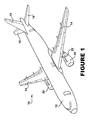
Figure 1 shows an aircraft having several surfaces protectable by the ice protection system. -
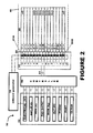
Figure 2 shows the ice protection system. -
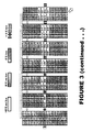
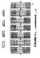
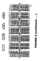
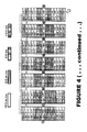
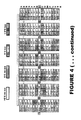
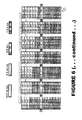
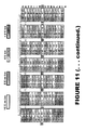
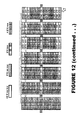
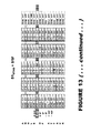
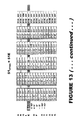
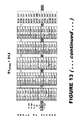
Figures 3-13 show some possible ice protection schemes. - An
aircraft 10, such as that shown inFigure 1 , can comprisefuselage 12,wings 14,horizontal stabilizers 16, avertical stabilizer 18,engines 20, andpylons 22. Thewings 14 are the aircraft's primary lift providers. Thehorizontal stabilizers 16 prevent up-down motion of the aircraft nose, and thevertical stabilizer 18 discourages side to side swinging. Theengines 20 are the aircraft's thrust-providing means and thepylons 22 serve as underling mounting means for the engines. - Referring now to
Figure 2 , anIce protection system 30 is shown in conjunction with an ice-susceptible aircraft surface 40. Theheater array 50 comprises a series ofconsecutive heaters 51A - 51O adapted to overlay thesurface 40. Thesurface 40 can be part of a wing, astabilizer 16/18, anengine 20, apylon 22 or any other ice-susceptible part of theaircraft 10. - The
ice protection system 30 further includes apower source 60 which supplies theheater array 50 with a dedicated supply of electrical energy from anonboard generator 70. Aheater interface 80 includes an electrical switch 81 for eachheater 51, and these switches 81 switch theirrespective heaters 51 between an ON condition and OFF condition. When in the ON condition, theenergized heater 51 receives substantially all of the electrical energy supplied to theheater array 50. When in the OFF condition, theheater 51 receives substantially none of the power supplied to theheater array 50. - A
controller 90 can convey instructions to the heater interface 80 (via line 91) or otherwise control the switching on and off of theheaters 51. Thecontroller 90 can base its instructions on derived directives, stored strategies, and/or information provided through an input panel 92 (e.g., electrical energy (VOLTS), outside air temperature (OAT), angle of attack (AOA), true air speed (TAS), weight on wheels (WOW), altitude (ALT), flight phase (PHASE), part position (PART), and/or cloud characteristics (CLOUD), etc.). - In the illustrated
system 30, theheater interface 80 is shown positioned adjacent to theheater array 50 and physically connected thereto. With such a layout, electrical energy can be provided through one supply cable routed between theheater array 50 and thegenerator 70. But aheater interface 80 that is remote from the heater array is possible and contemplated and, in fact, may be preferred to facilitate servicing. - As was indicated above, the
heater array 50 comprises a series ofconsecutive heaters 51A - 51O adapted to overlay thesurface 40. "Consecutive" In this context refers to theheaters 51A - 51O being arranged one after another in an aft-fore-aft path. Although thesurface 40, thearray 50, and theheaters 51 are drawn flat in the figures, this is simply for ease in illustration and explanation. Thesurface 40 will probably follow a non-linear roughly parabolic route (whereby theheater array 50 will adopt a similar course). - If the
surface area 40 is on one of thewings 14, for example, the heaters 50A - 50D could be situated on the wing's upper regions, the heaters 50E - 50K could wrap around fore regions, and the heaters 50L - 50O could be situated on the lower regions. An analogous heater arrangement could be used if thesurface area 40 is on one of thehorizontal stabilizers 16. - If the
surface area 40 is on thevertical stabilizer 18, the heaters 50A - 50D could be on rightside regions, the heaters 50E-50K could curve around fore regions, and the heaters 50L-50O could be leftside regions. Theheaters 51 could be likewise located if thesurface area 40 is on one of thepylons 22. And if thesurface area 40 is on one of theengines 20, the heaters 50A - 50D could be situated on outer regions, the heaters 50E - 50K could bend around the engine's lip, and the heaters 50L-50O could be situated on inner regions. - The
heaters 51 are purposely sized to cover relatively small surface areas (e.g., less than 500 cm2, less than 400 cm2, less than 300 cm7, less than 200 cm2, less than 100 cm2, etc.). If thesurface 40 has typical area dimensions (e.g., at least 0.10 m2, at least 0,20 m2, at least 0.30 m2, at least 0.40 m2, at least 0.5 m2, at least 1 m2, etc.), this will result in theheater array 50 having a generous number of heaters 51 (e.g. at least four, at least six, at least eight, at least ten, at least twelve, at least fourteen, at least sixteen, etc.). - The relatively small size of the
heaters 51 amplifies their power density for a given amount of electrical energy input. And because deicing time is indirectly proportional to the square of power density (i.e., deicing time = k/P2 where k is a constant), this exponentially reduces deicing time to a significantly shorter interval. Thus, with thesystem 30, ice protection steps can be completed in a shorter time frame without the dedication of additional electrical energy. - While the deicing-time equation theoretically implies that the archetype array would assimilate an enormous number of tiny heaters, other limiting factors are introduced into the equation. For example, to take optimum advantage of high power density, independent control of each of the
heaters 51 may be necessary. Thus, the weight, cost, and inconvenience of the corresponding control circuitry must be taken into consideration. Additionally or alternatively, minute heater sizes and/or multitude-heater arrays can introduce manufacturing obstacles, assembly complications, and/or installation impediments. These and other difficulties factor into the calculus of choosing appropriate heater sizes and/or array logistics. - Moreover, the stagnation region of the
aircraft surface 40, and the heater(s) 51 associated with this region may play prominently into the array architecture. The significance of the stagnation region Is that it is customarily considered to require unremitting anti-icing (i.e., the constant and continuous prevention of ice formation). The non-stagnation regions on the other hand, have conventionally been provided with intermittent deicing (i.e, the periodic removal of ice formation). - The heater(s) 51 associated with the stagnation region can be called the
stagnation heater 51STAG. Theremaining heaters 51 In the heater array 50 (which are not associated with the stagnation region) can be called thenon-stagnation heaters 51nonSTAG. This shorthand refers to current flight circumstances, as the location of the stagnation region (and thus the stagnation heater 51STAG) can change during the course of a flight. - An optimum array design may require the
stagnation heater 51STAG to have an aft-fore-aft dimension large enough to sufficiently cover the stagnation region of the surface 40 (e.g., at least 1 cm, at least 1.5 cm, at least 2 cm, etc.). At the same time, the most advantageous array may require avoiding making this dimension too large (e.g., less than 5 cm, less than 4.5 cm, less than 4 cm, less 3 cm, etc.). And, as this stagnation region will shift according to the aircraft's angle of attack, a range of fore heaters 51 (e.g., at least three fore heaters, at least five fore heaters, at least seven fore heaters, etc.) may need to share this significant aft-fore-aft dimension. - The illustrated congregation of
rectangular heaters 51 in a regular row is certainly not required. That being said, a thin rectangular geometry may often be the most convenient shape for theheaters 51. The aft-fore-aft dimension of the rectangle can be sized to accommodate the stagnation district and the transverse dimension can be made substantially greater (e.g., five times as great, ten times as great, fifteen times as great, etc.) to achieve the desired surface area. And although theheaters 51 all need not be the same size/shape, this may indeed be the most opportune array arrangement. - Depending upon the
aircraft 10 and the particular aircraft component, and/or expected flying conditions, more than one row ofheater arrays 50 may be necessary. With thewings 14, for example, two or threeheater arrays 50 can be arranged in the spanwise rows. With thehorizontal stabilizers 16, thevertical stabilizer 18 and/or thepylons 22, asingle heater array 50 may be sufficient. With theengine 20, five ormore heater arrays 50 can be arranged in radial rows circling the inlet lip. - Turning now to
Figures 3-7 , some ice protection schemes are schematically diagrammed. In these schemes, ice-protection steps are conceptually divided into heating episodes. Each heating episode involves the stagnation heater 51STAG (i.e.,heater 51H in theFigures 3 - 7 ) and at least one other non-stagnation heater 51 (i.e., one ofheaters 51A - 51G or 51I - 51O inFigures 3 - 7 ). The heating episode is then reiterated until eachnon-stagnation heater 51 has been involved to complete a session. Sessions can be repeated for as long as ice protection is required. - In the ice-protection schemes shown in
Figures 3 - 7 , only oneheater 51 is an ON condition at a time, whereby it receives substantially all of the electrical energy supplied to theheater array 50. Thisheater 51 is switched to an OFF condition (whereat receives substantially none of the power supplied to the heater array 50) before anotherheater 51 is switched ON. This ON-OFF switching can occur almost instantaneously and, in the drawings, appears to happen at the same time. - The
system 30 allows ice-protection schemes wherein the stagnation heater 51STAG (again,heater 51H inFigures 3 - 7 ) can accomplish anti-icing without remaining continuously in the ON condition. In the illustrated schemes, thestagnation heater 51STAG is involved in every episode. More specifically, during each episode, thestagnation heater 51STAG Is switched ON for an interval and it is switched OFF for an interlude (so that anon-stagnation heater 51 can be switched ON). - The interval period Is purposely long enough to allow the stagnation region to overheat to a temperature greater than 0° C. And the interlude period is strategically brief enough so that stagnation region will not have the chance to cool down to freezing temperatures. The interval period and the interlude period can be the same or different, depending upon what is necessary to accomplish these temperature tactics. And either or both of these time periods can be a predetermined value based on worst-case flight conditions or they can be calculated based on current flight circumstances. In many instances, the interval period and/or the interlude period will be less than 1 second (and/or less than 0.75 second, etc.) but greater than 0.10 second (and/or greater than 0.20 second, greater than 0.30 second, greater than 0.40 second, greater than 0.50 second, etc.).
- In
Figure 3 , the first heating episode comprises switching ON thestagnation heater 51H for the appropriate time Interval, switching OFF thestagnation heater 51, switching ON theheater 51G for the time interlude, and then switching OFF theheater 51G. The second heating episode comprises switching ON thestagnation heater 51H for the time interval, switching OFF thestagnation heater 51, switching ON the heater 51I for the time interlude, and then switching OFF the heater 51I. The third heating episode comprises switching ON thestagnation heater 51H for the time interval, switching OFF thestagnation heater 51, switching ON theheater 51F for the time interlude, and then switching OFF theheater 51F. These heating episodes continue in this alternate-side fore-to-aft pattern until all of thenon-stagnation heaters 51 have been involved in heating episode. - In
Figure 4 , the first heating episode comprises switching ON thestagnation heater 51H for the appropriate time interval, switching OFF thestagnation heater 51, switching ON theheater 51A for the time interlude, and then switching OFF theheater 51A. The second heating episode comprises switching ON thestagnation heater 51H for the time interval, switching OFF thestagnation heater 51, switching ON the heater 51O for the time interlude, and then switching OFF the heater 51O. The third heating episode composes switching ON thestagnation heater 51H for the time interval, switching OFF thestagnation heater 51, switching ON theheater 51B for the time interlude, and then switching OFF theheater 51B, These heating episodes continue in this alternate-side aft-to-fore pattern until all of thenon-stagnation heaters 51 have been involved in heating episode. - In
Figure 5 , the first heating episode comprises switching ON thestagnation heater 51H for the appropriate time interval, switching OFF thestagnation heater 51, switching ON theheater 51G for the time interlude, and then switching OFF theheater 51G. The second heating episode comprises switching ON thestagnation heater 51H for the time interval, switching OFF thestagnation heater 51, switching ON theheater 51F for the time interlude, and then switching OFF theheater 51F. The third heating episode comprises switching ON thestagnation heater 51H for the time interval, switching OFF thestagnation heater 51H, switching ON theheater 51E for the time interlude, and then switching OFF theheater 51E. These heating episodes continue in the fore-aft direction on this one side of thestagnation heater 51H until theaftmost heater 51A is involved in a heating episode. The next episode then involves heater 51I on the other side of thestagnation heater 51H and this same-side fore-aft pattern continues until all of thenon-stagnation heaters 51 have been involved in heating episode. - In
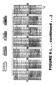
Figure 6 , a same-side pattern similar to that ofFigure 5 is followed by the heating episodes, except in the aft-fore direction. The first heating episode comprises switching ON thestagnation heater 51H for the appropriate time interval, switching OFF thestagnation heater 51, switching ON theheater 51A for the time Interlude, and then switching OFF theheater 51A. The second heating episode comprises switching ON thestagnation heater 51H for the time interval, switching OFF thestagnation heater 51, switching ON the heater 51O for the time interlude, and then switching OFF the heater 51O. The third heating episode comprises switching ON thestagnation heater 51H for the time interval, switching OFF thestagnation heater 51H, switching ON theheater 51B for the time interlude, and then switching OFF theheater 51B. This same-side aft-fore pattern continues until all of thenon-stagnation heaters 51 have been involved in heating episode. - In
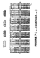
Figure 7 , the first heating episode comprises switching ON thestagnation heater 51H for the appropriate time interval, switching OFF thestagnation heater 51H, switching ON theheater 51A for the time interlude, and then switching OFF theheater 51A. The second heating episode comprises switching ON thestagnation heater 51H for the time interval, switching OFF thestagnation heater 51H, switching ON theheater 51B for the time interlude, and then switching OFF theheater 51B. The third heating episode comprises switching ON thestagnation heater 51H for the time interval, switching OFF thestagnation heater 51H, switching ON theheater 51C for the time interlude, and then switching OFF theheater 51C. This is continued untilheater 51G is involved in a heating episode and then next episode involves heater 51I. This aft-fore-aft pattern continues untilheater 510 is involved in a heating episode. - In sessions shown in
Figures 3 - 7 , the first heating episode is in the upper (in the illustrated orientation) side of thestagnation heater 51H. This could be reversed and the relevant patterns practiced by starting on the opposite side of thestagnation heater 51H. After a first session is completed the inter-side sequence may be somewhat moot, but in some instances, order may be pertinent for the first session. For example, with the sudden onset of icing, it may be best to promptly deice the inner surface of anengine 20, while its outer surface can tolerate a deicing delay without consequences. - In sessions shown in
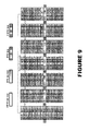
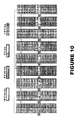
Figures 3 - 7 , thenon-stagnation heaters 51nonSTAG are on for one interlude during each heating episode. In colder circumstances, this could be insufficient to heat the corresponding region of theaircraft surface 40 to an above-freezing temperature. If so, each heating episodes can be expanded to include plural interludes wherein thesame non-stagnation heater 51nonSTAG is energized. For example, each heating episode can be extended to include two interludes (Figure 8 ), three interludes (Figure 9 ), four interludes (Figure 10 ), or more interludes if necessary or beneficial. - In the sessions shown in
Figures 3 - 10 , only onenon-stagnation heater 51nonSTAG is involved in each heating episode. However, as shown inFigure 12 andFigure 13 , two-heater episodes are also possible. The twonon-stagnation heaters 51nonSTAG involved in a particular heating episode can (but need not) be symmetrically arranged relative to thestagnation heater 51STAG. Reiterations can progress in a fore-to-aft pattern as shown inFigure 11 , in an aft-to-fore pattern as shown inFigure 12 , or in any other appropriate pattern. - In the ice-protection schemes shown in
Figures 3 - 12 , theheater 51H is thestagnation heater 51STAG and, as shown inFigure 13 , this could be the case if the angle of attack is equal to 0°. However, as is also shown inFigure 13 , as the angle of attack changes, the stagnation region changes, and thusstagnation heater 51STAG will change identities within thearray 50. When this happens, the heating episodes can adjust as appropriate to involve the real-time stagnation heater 51STAG in each heating episode. Theice protection system 30 can be designed to accommodate the expected angles of attack (e.g., -5° to +5°, -10° to +10°, -15° to +15°, etc.). - In the Ice protection schemes shown in
Figures 3 - 13 , thestagnation heater 51STAG is turned ON for an interval and turned OFF for an interludes during each heating episode. For most aircrafts and in most flight circumstances, the interval and the interlude can be selected to prevent icing on the stagnation region. However, thecontroller 90 preferably also allows a heating session wherein the stagnation heater 51STAG remains continuously on to accommodate extremely cold temperatures (e.g., less than 20° C). - One may now appreciate that, with the
ice protection system 30, aheater array 50 can be architected that effectively and efficiently protects aircraft surface. - It will be understood that the present invention has been described above purely by way of example, and modifications of detail can be made within the scope of the invention.
- Each feature disclosed in the description, and (where appropriate) the claims and drawings may be provided independently or in any appropriate combination.
Claims (15)
- An ice protection system (30) comprising:a heater array (50) comprising a series of consecutive electrothermal heaters (51) which proceed one after another in a substantially aft-fore-aft path, one of the heaters (51) being a stagnation heater (51STAG) and the rest the heaters (51) being non-stagnation heaters (51nonSTAG);a power source (60) which supplies the heater array (50) with electrical energy from an onboard generator (70);a heater interface (80) that switches each heater (51) into either an ON condition or an OFF condition; anda controller (90) that controllers the heater interface (80) to execute a heating episode involving the stagnation heater (51STAG) and at least one non-stagnation heater (51nonSTAG) and then reiterates this heating episode for the remaining non-stagnation heaters (51nonSTAG);wherein each heating episode includes an interval during which the stagnation heater (51STAG) is in the ON condition and an interlude during which the stagnation heater (51STAG) is in the OFF condition;wherein during the interval when the stagnation heater (51STAG) is in the ON condition, the non-stagnation heaters (51STAG) are in the OFF condition whereby the stagnation heater (51STAG) receives substantially all of the power supplied to the heater array (50); andwherein during the interlude when the stagnation heater (51STAG) is in the OFF condition, the involved non-stagnation heater(s) (51nonSTAG) is/are in the ON condition, and the non-involved non-stagnation heaters (51nonSTAG) are in the OFF condition, whereby the involved non-stagnation heater(s) (51nonSTAG) receives substantially all of the power supplied to the heater array (50).
- An ice protection system (30) as set forth in the preceding claim, wherein the interval is long enough to allow the stagnation region to overheat to a temperature greater than 0°C and wherein the interlude is short enough so that stagnation region will not have the chance to cool down to freezing temperatures.
- An ice protection system (30) as set forth in either of the two preceding claims, wherein the controller (90) controls the heater interface (80) so that, during each heating episode, the stagnation heater (51STAG) is switched to the ON condition for at least one interval and then switched to the OFF condition for at least one interval.
- An ice protection system (30) as set forth in any of claims 1-3, wherein each heating episode involves only one non-stagnation heater (51nonSTAG).
- An ice protection system (30) as set forth in any of claims 1-3, wherein each heating episode involves at least two non-stagnation heaters (51nonSTAG).
- An ice protection system (30) as set forth in any of the preceding claims, wherein the controller (90) controls the heater interface (80) so that the stagnation heater (51STAG) shifts location based on flight circumstances.
- An ice protection system (30) as set forth in any of the preceding claims, wherein at least three of the fore heaters (51) each have an aft-fore dimension of less than 3 cm.
- An ice protection system (30) as set forth in any of the preceding claims, wherein the heaters (51) each cover a surface area of less 200 cm2.
- An ice protection system (30) as set forth in any of the preceding claims, wherein the heater array (50) comprises at least seven heaters (51).
- An ice protection system (30) as set forth in any of the preceding claims, wherein the interludes and the intervals are each less than 1 second and greater than 0.10 second.
- An ice protection system (30) as set forth in any of the preceding claims, wherein the heater array (50) covers a surface area of at least 1000 cm2 and less than 10 m2.
- An ice protection system (30) as set forth in any of the preceding claims, wherein the power density of each heater (51) when in its ON condition is at least 5 W/cm2.
- An ice protection system (30) as set forth in any of the preceding claims, wherein the controller (90) controls the heater interface (80) so that the heating episode is reiterated for the remaining non-stagnation heater (51nonSTAG) in an alternate-side-fore-aft pattern, an alternate-side-aft-fore pattern, a same-side-fore-aft pattern, a same-side-aft-fore pattern, or an aft-fore-aft pattern.
- An ice protection system (30) as set forth in any of the preceding claims, wherein the pattern is reiterated until all of the non-stagnation heaters (51nonSTAG) have been involved in a heating episode.
- An aircraft (10) comprising an ice-susceptible surface (40) and the ice protection system (30) set forth in any of the preceding claims installed to protect this surface (40).
Applications Claiming Priority (1)
| Application Number | Priority Date | Filing Date | Title |
|---|---|---|---|
| US31878610P | 2010-03-29 | 2010-03-29 |
Publications (2)
| Publication Number | Publication Date |
|---|---|
| EP2374715A2 true EP2374715A2 (en) | 2011-10-12 |
| EP2374715A3 EP2374715A3 (en) | 2014-01-22 |
Family
ID=44507066
Family Applications (1)
| Application Number | Title | Priority Date | Filing Date |
|---|---|---|---|
| EP11250220.8A Withdrawn EP2374715A3 (en) | 2010-03-29 | 2011-02-25 | Aircraft ice protection system |
Country Status (3)
| Country | Link |
|---|---|
| US (1) | US20110233340A1 (en) |
| EP (1) | EP2374715A3 (en) |
| CA (1) | CA2735005A1 (en) |
Cited By (2)
| Publication number | Priority date | Publication date | Assignee | Title |
|---|---|---|---|---|
| RU2543447C2 (en) * | 2012-04-18 | 2015-02-27 | Российская Федерация, от имени которой выступает Министерство промышленности и торговли (Минпромторг России) | Method of icing control and device for its realisation |
| EP2692640A3 (en) * | 2012-07-31 | 2017-04-19 | Goodrich Corporation | Ice protection system |
Families Citing this family (1)
| Publication number | Priority date | Publication date | Assignee | Title |
|---|---|---|---|---|
| GB2511343B (en) * | 2013-02-28 | 2015-07-22 | Gkn Aerospace Services Ltd | Ice protection system |
Family Cites Families (58)
| Publication number | Priority date | Publication date | Assignee | Title |
|---|---|---|---|---|
| US2496279A (en) * | 1945-02-10 | 1950-02-07 | Safeway Heat Elements Inc | Flexible electric heater for deicing airfoils |
| US2599059A (en) * | 1945-07-31 | 1952-06-03 | Goodrich Co B F | Means for preventing ice accumulation on airfoils |
| US2762897A (en) * | 1951-06-28 | 1956-09-11 | Lockheed Aircraft Corp | De-icing means for aircraft and the like |
| US2757273A (en) * | 1952-12-12 | 1956-07-31 | Goodyear Tire & Rubber | De-icer |
| US2992317A (en) * | 1957-10-14 | 1961-07-11 | Goodrich Co B F | Electrically heated ice-removal apparatus |
| US3022412A (en) * | 1958-09-26 | 1962-02-20 | Goodyear Tire & Rubber | Deicer |
| US3013752A (en) * | 1959-10-01 | 1961-12-19 | Ca Nat Research Council | De-icing control |
| GB991405A (en) * | 1960-05-19 | 1965-05-05 | Dehavilland Aircraft | Improvements relating to aircraft |
| US3002718A (en) * | 1960-07-08 | 1961-10-03 | Kaman Aircraft Corp | Rotor blade deicing system |
| US3204084A (en) * | 1963-05-07 | 1965-08-31 | Gen Dynamics Corp | Electrical deicer |
| GB1167575A (en) * | 1966-04-28 | 1969-10-15 | Licentia Gmbh | De-Icing Installation for Aircraft |
| DE1273337B (en) * | 1966-05-04 | 1968-07-18 | Hamburger Flugzeugbau G M B H | De-icing system for aircraft |
| US3549964A (en) * | 1968-03-01 | 1970-12-22 | Levin Igor A | Device for deicing surfaces of thin-walled structures |
| DE2443224C3 (en) * | 1974-09-10 | 1979-02-22 | Licentia Patent-Verwaltungs-Gmbh, 6000 Frankfurt | Process for deicing engine, wing and tail unit systems on missiles |
| US5415770A (en) * | 1984-04-30 | 1995-05-16 | Kdf Fluid Treatment, Inc. | Apparatus for treating fluids |
| US4678144A (en) * | 1984-10-26 | 1987-07-07 | Simmonds Precision | Electro-impulse de-icing system for aircraft |
| US4814931A (en) * | 1987-01-15 | 1989-03-21 | The B. F. Goodrich Company | Apparatus and method for timed-de-icing |
| US5006267A (en) * | 1989-11-08 | 1991-04-09 | The Dow Chemical Company | Biocidal fluid filters |
| US4995976A (en) * | 1990-05-31 | 1991-02-26 | Water Technologies Corporation | Water purification straw |
| EP0459216A3 (en) * | 1990-06-01 | 1993-03-17 | The Bfgoodrich Company | Electrical heater de-icer |
| US5580447A (en) * | 1991-04-09 | 1996-12-03 | Sweetwater, Inc. | Biocide filter |
| US5269919A (en) * | 1992-01-17 | 1993-12-14 | Von Medlin Wallace | Self-contained water treatment system |
| US5407573A (en) * | 1993-06-01 | 1995-04-18 | Alpine Water Purification, Inc. | Continuous flow water-purifying device |
| GB9502905D0 (en) * | 1995-02-15 | 1995-04-05 | Dunlop Ltd | Ice protection device |
| US5657951A (en) * | 1995-06-23 | 1997-08-19 | The B.F. Goodrich Company | Electrothermal de-icing system |
| US6854601B2 (en) * | 1995-12-15 | 2005-02-15 | Microban Products Company | Bacteriostatic filter cartridge |
| FR2756253B1 (en) * | 1996-11-27 | 1999-01-29 | Eurocopter France | RESISTIVE ELEMENTS FOR HEATING AN AERODYNAMIC PROFILE, AND DEVICE FOR HEATING AN AERODYNAMIC PROFILE INCORPORATING SUCH ELEMENTS |
| FR2756254B1 (en) * | 1996-11-27 | 1999-01-29 | Eurocopter France | DEVICE FOR HEATING AN AERODYNAMIC PROFILE |
| US5925243A (en) * | 1997-02-11 | 1999-07-20 | Dana Corporation | Inline cartridge filter |
| US6279856B1 (en) * | 1997-09-22 | 2001-08-28 | Northcoast Technologies | Aircraft de-icing system |
| US5934617A (en) * | 1997-09-22 | 1999-08-10 | Northcoast Technologies | De-ice and anti-ice system and method for aircraft surfaces |
| US6283411B1 (en) * | 1998-01-21 | 2001-09-04 | The B.F. Goodrich Company | Hybrid deicer with element sequence control |
| FR2779314B1 (en) * | 1998-05-27 | 2000-08-04 | Eurocopter France | HEATING DEVICE WITH RESISTIVE ELEMENTS OF AN AERODYNAMIC PROFILE |
| CA2273745A1 (en) * | 1999-06-04 | 2000-12-04 | George W. Thorpe | Fluid sterilization apparatus |
| WO2003069955A1 (en) * | 2002-02-11 | 2003-08-21 | The Trustees Of Dartmouth College | Systems and methods for modifying an ice-to-object interface |
| US7196436B2 (en) * | 2003-04-03 | 2007-03-27 | Goodrich Corporation | Solid state relay for switching AC power to a reactive load and method of operating the same |
| US7396459B2 (en) * | 2003-05-05 | 2008-07-08 | George W Thorpe | Internal UV treatment of potable water systems |
| FR2863586B1 (en) * | 2003-12-12 | 2007-01-19 | Eurocopter France | MODULAR DEFROST / DEFROSTING DEVICE FOR AERODYNAMIC SURFACE. |
| GB2440289B (en) * | 2004-01-30 | 2008-09-17 | Ultra Electronics Ltd | Modular aircraft control system and method |
| US7278610B2 (en) * | 2004-03-03 | 2007-10-09 | Goodrich Corporation | Aircraft wing with electrothermal deicing and/or anti-icing device |
| US7763833B2 (en) * | 2004-03-12 | 2010-07-27 | Goodrich Corp. | Foil heating element for an electrothermal deicer |
| US7246773B2 (en) * | 2004-05-06 | 2007-07-24 | Goodrich Coporation | Low power, pulsed, electro-thermal ice protection system |
| US7124983B2 (en) * | 2004-08-20 | 2006-10-24 | Honeywell International, Inc. | Hybrid electrical ice protection system and method including an energy saving mode |
| US7211772B2 (en) * | 2005-03-14 | 2007-05-01 | Goodrich Corporation | Patterned electrical foil heater element having regions with different ribbon widths |
| US7469862B2 (en) * | 2005-04-22 | 2008-12-30 | Goodrich Corporation | Aircraft engine nacelle inlet having access opening for electrical ice protection system |
| US7513458B2 (en) * | 2005-04-22 | 2009-04-07 | Rohr, Inc. | Aircraft engine nacelle inlet having electrical ice protection system |
| EP1893484B1 (en) * | 2005-06-22 | 2010-11-03 | Airbus Operations (S.A.S) | Anti-icing and de-icing system for aircraft engine pod with resistive mat |
| DE102006031330B4 (en) * | 2005-07-14 | 2014-03-20 | Goodrich Corp. | An ice-susceptible portion of an aircraft, in particular an aircraft engine cell inlet lip, comprising an ice protection system, aircraft engine having such an inlet lip, and a method of protecting such inlet lip from icing |
| US20070131872A1 (en) * | 2005-12-09 | 2007-06-14 | Shearer Jon D | Water-purification device for a potable water system |
| US7828247B2 (en) * | 2006-01-12 | 2010-11-09 | Safe Flight Instrument Corporation | Automatic recycling ice detector |
| US7291815B2 (en) * | 2006-02-24 | 2007-11-06 | Goodrich Corporation | Composite ice protection heater and method of producing same |
| US20090230239A1 (en) * | 2006-03-17 | 2009-09-17 | Stothers Ian Mcgregor | Ice protection power supply |
| FR2903074B1 (en) * | 2006-06-28 | 2010-08-20 | Goodrich Corp | DEFROSTING METHOD FOR AN AIRCRAFT |
| GB2450503A (en) * | 2007-06-26 | 2008-12-31 | Ultra Electronics Ltd | Ice protection system with plural heating elements |
| US7922121B2 (en) * | 2007-10-15 | 2011-04-12 | Rosemount Aerospace Inc. | Power distribution architecture for an ice protection system |
| US7837150B2 (en) * | 2007-12-21 | 2010-11-23 | Rohr, Inc. | Ice protection system for a multi-segment aircraft component |
| US20100123044A1 (en) * | 2008-11-17 | 2010-05-20 | Botura Galdemir C | Aircraft Ice Protection System |
| CA2686836C (en) * | 2008-12-01 | 2017-04-11 | International Water-Guard Industries, Inc. | Water distribution system with dual use water treatment unit |
-
2011
- 2011-02-22 US US13/032,296 patent/US20110233340A1/en not_active Abandoned
- 2011-02-25 EP EP11250220.8A patent/EP2374715A3/en not_active Withdrawn
- 2011-03-25 CA CA2735005A patent/CA2735005A1/en not_active Abandoned
Non-Patent Citations (1)
| Title |
|---|
| None |
Cited By (2)
| Publication number | Priority date | Publication date | Assignee | Title |
|---|---|---|---|---|
| RU2543447C2 (en) * | 2012-04-18 | 2015-02-27 | Российская Федерация, от имени которой выступает Министерство промышленности и торговли (Минпромторг России) | Method of icing control and device for its realisation |
| EP2692640A3 (en) * | 2012-07-31 | 2017-04-19 | Goodrich Corporation | Ice protection system |
Also Published As
| Publication number | Publication date |
|---|---|
| EP2374715A3 (en) | 2014-01-22 |
| CA2735005A1 (en) | 2011-09-29 |
| US20110233340A1 (en) | 2011-09-29 |
Similar Documents
| Publication | Publication Date | Title |
|---|---|---|
| EP2195238B1 (en) | Ice protection heater system | |
| US6196500B1 (en) | Hybrid ice protection system for use on roughness-sensitive airfoils | |
| EP1968854B1 (en) | Energy-efficient electro-thermal ice-protection system | |
| EP2112353B1 (en) | Aircraft engine nacelle inlet | |
| US7124983B2 (en) | Hybrid electrical ice protection system and method including an energy saving mode | |
| EP1715160B1 (en) | Aircraft engine nacelle inlet having electrical ice protection system | |
| US8857767B2 (en) | De-icing system for an aircraft | |
| US7938368B2 (en) | Nosecone ice protection system for a gas turbine engine | |
| US20120091276A1 (en) | Energy-efficient electro-thermal and electro-mechanical ice-protection method | |
| EP2796372B1 (en) | Resistive-inductive de-icing of aircraft flight control surfaces | |
| JP5384901B2 (en) | Power distribution structure for anti-icing device | |
| US20130228653A1 (en) | Electrothermal and electro expulsive hybrid ice protection system for engine inlet | |
| US20110233340A1 (en) | Aircraft ice protection system | |
| EP4301659B1 (en) | System and method for generating electrical energy from thermal waste energy and removing thermal waste energy in an aircraft | |
| CN109625289B (en) | Deicing device is prevented to aircraft based on solar energy | |
| EP2692640A2 (en) | Ice protection system | |
| EP3650349B1 (en) | De-icing system and method | |
| US11794908B2 (en) | Flow body for an aircraft having an integrated de-icing system | |
| WO2014088481A1 (en) | De-icing arrangement and method for de-icing a structural element | |
| EP1873060B1 (en) | Hybrid electrical ice protection system and method including an energy saving mode | |
| US9566921B2 (en) | Appliance insert connection interface for an aircraft galley | |
| CN112046760B (en) | Airplane wing deicing and radar heat dissipation comprehensive control system and method | |
| US11975848B2 (en) | Method for operating a frost treatment system combining at least two heating mats and outer aircraft wall comprising a frost treatment system operating according to this method | |
| KR101838596B1 (en) | Deicing device using piezoelectric element | |
| CN214566187U (en) | Electric heating ice preventing and removing system of distributed unmanned aerial vehicle |
Legal Events
| Date | Code | Title | Description |
|---|---|---|---|
| PUAI | Public reference made under article 153(3) epc to a published international application that has entered the european phase |
Free format text: ORIGINAL CODE: 0009012 |
|
| 17P | Request for examination filed |
Effective date: 20110314 |
|
| AK | Designated contracting states |
Kind code of ref document: A2 Designated state(s): AL AT BE BG CH CY CZ DE DK EE ES FI FR GB GR HR HU IE IS IT LI LT LU LV MC MK MT NL NO PL PT RO RS SE SI SK SM TR |
|
| AX | Request for extension of the european patent |
Extension state: BA ME |
|
| PUAL | Search report despatched |
Free format text: ORIGINAL CODE: 0009013 |
|
| AK | Designated contracting states |
Kind code of ref document: A3 Designated state(s): AL AT BE BG CH CY CZ DE DK EE ES FI FR GB GR HR HU IE IS IT LI LT LU LV MC MK MT NL NO PL PT RO RS SE SI SK SM TR |
|
| AX | Request for extension of the european patent |
Extension state: BA ME |
|
| RIC1 | Information provided on ipc code assigned before grant |
Ipc: B64D 15/14 20060101AFI20131218BHEP |
|
| STAA | Information on the status of an ep patent application or granted ep patent |
Free format text: STATUS: THE APPLICATION IS DEEMED TO BE WITHDRAWN |
|
| 18D | Application deemed to be withdrawn |
Effective date: 20140723 |