EP2374600A1 - Kneading disk with tapered crest surface - Google Patents
Kneading disk with tapered crest surface Download PDFInfo
- Publication number
- EP2374600A1 EP2374600A1 EP10159622A EP10159622A EP2374600A1 EP 2374600 A1 EP2374600 A1 EP 2374600A1 EP 10159622 A EP10159622 A EP 10159622A EP 10159622 A EP10159622 A EP 10159622A EP 2374600 A1 EP2374600 A1 EP 2374600A1
- Authority
- EP
- European Patent Office
- Prior art keywords
- edge
- kneading disk
- crest surface
- kneading
- screw extruder
- Prior art date
- Legal status (The legal status is an assumption and is not a legal conclusion. Google has not performed a legal analysis and makes no representation as to the accuracy of the status listed.)
- Granted
Links
Images
Classifications
-
- B—PERFORMING OPERATIONS; TRANSPORTING
- B29—WORKING OF PLASTICS; WORKING OF SUBSTANCES IN A PLASTIC STATE IN GENERAL
- B29B—PREPARATION OR PRETREATMENT OF THE MATERIAL TO BE SHAPED; MAKING GRANULES OR PREFORMS; RECOVERY OF PLASTICS OR OTHER CONSTITUENTS OF WASTE MATERIAL CONTAINING PLASTICS
- B29B7/00—Mixing; Kneading
- B29B7/30—Mixing; Kneading continuous, with mechanical mixing or kneading devices
- B29B7/34—Mixing; Kneading continuous, with mechanical mixing or kneading devices with movable mixing or kneading devices
- B29B7/38—Mixing; Kneading continuous, with mechanical mixing or kneading devices with movable mixing or kneading devices rotary
- B29B7/46—Mixing; Kneading continuous, with mechanical mixing or kneading devices with movable mixing or kneading devices rotary with more than one shaft
- B29B7/48—Mixing; Kneading continuous, with mechanical mixing or kneading devices with movable mixing or kneading devices rotary with more than one shaft with intermeshing devices, e.g. screws
- B29B7/481—Mixing; Kneading continuous, with mechanical mixing or kneading devices with movable mixing or kneading devices rotary with more than one shaft with intermeshing devices, e.g. screws provided with paddles, gears or discs
-
- B—PERFORMING OPERATIONS; TRANSPORTING
- B29—WORKING OF PLASTICS; WORKING OF SUBSTANCES IN A PLASTIC STATE IN GENERAL
- B29B—PREPARATION OR PRETREATMENT OF THE MATERIAL TO BE SHAPED; MAKING GRANULES OR PREFORMS; RECOVERY OF PLASTICS OR OTHER CONSTITUENTS OF WASTE MATERIAL CONTAINING PLASTICS
- B29B7/00—Mixing; Kneading
- B29B7/30—Mixing; Kneading continuous, with mechanical mixing or kneading devices
- B29B7/34—Mixing; Kneading continuous, with mechanical mixing or kneading devices with movable mixing or kneading devices
- B29B7/38—Mixing; Kneading continuous, with mechanical mixing or kneading devices with movable mixing or kneading devices rotary
- B29B7/46—Mixing; Kneading continuous, with mechanical mixing or kneading devices with movable mixing or kneading devices rotary with more than one shaft
- B29B7/48—Mixing; Kneading continuous, with mechanical mixing or kneading devices with movable mixing or kneading devices rotary with more than one shaft with intermeshing devices, e.g. screws
- B29B7/488—Parts, e.g. casings, sealings; Accessories, e.g. flow controlling or throttling devices
- B29B7/489—Screws
-
- B—PERFORMING OPERATIONS; TRANSPORTING
- B29—WORKING OF PLASTICS; WORKING OF SUBSTANCES IN A PLASTIC STATE IN GENERAL
- B29C—SHAPING OR JOINING OF PLASTICS; SHAPING OF MATERIAL IN A PLASTIC STATE, NOT OTHERWISE PROVIDED FOR; AFTER-TREATMENT OF THE SHAPED PRODUCTS, e.g. REPAIRING
- B29C48/00—Extrusion moulding, i.e. expressing the moulding material through a die or nozzle which imparts the desired form; Apparatus therefor
- B29C48/25—Component parts, details or accessories; Auxiliary operations
- B29C48/36—Means for plasticising or homogenising the moulding material or forcing it through the nozzle or die
- B29C48/395—Means for plasticising or homogenising the moulding material or forcing it through the nozzle or die using screws surrounded by a cooperating barrel, e.g. single screw extruders
- B29C48/40—Means for plasticising or homogenising the moulding material or forcing it through the nozzle or die using screws surrounded by a cooperating barrel, e.g. single screw extruders using two or more parallel screws or at least two parallel non-intermeshing screws, e.g. twin screw extruders
-
- B—PERFORMING OPERATIONS; TRANSPORTING
- B29—WORKING OF PLASTICS; WORKING OF SUBSTANCES IN A PLASTIC STATE IN GENERAL
- B29C—SHAPING OR JOINING OF PLASTICS; SHAPING OF MATERIAL IN A PLASTIC STATE, NOT OTHERWISE PROVIDED FOR; AFTER-TREATMENT OF THE SHAPED PRODUCTS, e.g. REPAIRING
- B29C48/00—Extrusion moulding, i.e. expressing the moulding material through a die or nozzle which imparts the desired form; Apparatus therefor
- B29C48/25—Component parts, details or accessories; Auxiliary operations
- B29C48/36—Means for plasticising or homogenising the moulding material or forcing it through the nozzle or die
- B29C48/395—Means for plasticising or homogenising the moulding material or forcing it through the nozzle or die using screws surrounded by a cooperating barrel, e.g. single screw extruders
- B29C48/40—Means for plasticising or homogenising the moulding material or forcing it through the nozzle or die using screws surrounded by a cooperating barrel, e.g. single screw extruders using two or more parallel screws or at least two parallel non-intermeshing screws, e.g. twin screw extruders
- B29C48/405—Intermeshing co-rotating screws
-
- B—PERFORMING OPERATIONS; TRANSPORTING
- B29—WORKING OF PLASTICS; WORKING OF SUBSTANCES IN A PLASTIC STATE IN GENERAL
- B29C—SHAPING OR JOINING OF PLASTICS; SHAPING OF MATERIAL IN A PLASTIC STATE, NOT OTHERWISE PROVIDED FOR; AFTER-TREATMENT OF THE SHAPED PRODUCTS, e.g. REPAIRING
- B29C48/00—Extrusion moulding, i.e. expressing the moulding material through a die or nozzle which imparts the desired form; Apparatus therefor
- B29C48/25—Component parts, details or accessories; Auxiliary operations
- B29C48/36—Means for plasticising or homogenising the moulding material or forcing it through the nozzle or die
- B29C48/50—Details of extruders
- B29C48/505—Screws
- B29C48/57—Screws provided with kneading disc-like elements, e.g. with oval-shaped elements
-
- B—PERFORMING OPERATIONS; TRANSPORTING
- B29—WORKING OF PLASTICS; WORKING OF SUBSTANCES IN A PLASTIC STATE IN GENERAL
- B29C—SHAPING OR JOINING OF PLASTICS; SHAPING OF MATERIAL IN A PLASTIC STATE, NOT OTHERWISE PROVIDED FOR; AFTER-TREATMENT OF THE SHAPED PRODUCTS, e.g. REPAIRING
- B29C48/00—Extrusion moulding, i.e. expressing the moulding material through a die or nozzle which imparts the desired form; Apparatus therefor
- B29C48/03—Extrusion moulding, i.e. expressing the moulding material through a die or nozzle which imparts the desired form; Apparatus therefor characterised by the shape of the extruded material at extrusion
-
- B—PERFORMING OPERATIONS; TRANSPORTING
- B29—WORKING OF PLASTICS; WORKING OF SUBSTANCES IN A PLASTIC STATE IN GENERAL
- B29C—SHAPING OR JOINING OF PLASTICS; SHAPING OF MATERIAL IN A PLASTIC STATE, NOT OTHERWISE PROVIDED FOR; AFTER-TREATMENT OF THE SHAPED PRODUCTS, e.g. REPAIRING
- B29C48/00—Extrusion moulding, i.e. expressing the moulding material through a die or nozzle which imparts the desired form; Apparatus therefor
- B29C48/25—Component parts, details or accessories; Auxiliary operations
- B29C48/256—Exchangeable extruder parts
- B29C48/2564—Screw parts
-
- B—PERFORMING OPERATIONS; TRANSPORTING
- B29—WORKING OF PLASTICS; WORKING OF SUBSTANCES IN A PLASTIC STATE IN GENERAL
- B29C—SHAPING OR JOINING OF PLASTICS; SHAPING OF MATERIAL IN A PLASTIC STATE, NOT OTHERWISE PROVIDED FOR; AFTER-TREATMENT OF THE SHAPED PRODUCTS, e.g. REPAIRING
- B29C48/00—Extrusion moulding, i.e. expressing the moulding material through a die or nozzle which imparts the desired form; Apparatus therefor
- B29C48/25—Component parts, details or accessories; Auxiliary operations
- B29C48/36—Means for plasticising or homogenising the moulding material or forcing it through the nozzle or die
- B29C48/395—Means for plasticising or homogenising the moulding material or forcing it through the nozzle or die using screws surrounded by a cooperating barrel, e.g. single screw extruders
- B29C48/40—Means for plasticising or homogenising the moulding material or forcing it through the nozzle or die using screws surrounded by a cooperating barrel, e.g. single screw extruders using two or more parallel screws or at least two parallel non-intermeshing screws, e.g. twin screw extruders
- B29C48/402—Means for plasticising or homogenising the moulding material or forcing it through the nozzle or die using screws surrounded by a cooperating barrel, e.g. single screw extruders using two or more parallel screws or at least two parallel non-intermeshing screws, e.g. twin screw extruders the screws having intermeshing parts
Definitions
- the invention relates to the field of polymer extrusion.
- the invention relates to a kneading disk for a screw extruder, a screw extruder, a use of a kneading disk for a screw extruder and a method of mixing a first material and a second material with a screw extruder.
- Screw extrusion may be used for mixing, compounding or reacting polymeric materials, like, for example, polyethylene or dough for noodles.
- the polymer material may be placed into a hopper of a screw extruder which has at least one screw for conveying the polymer material into the direction of a die.
- a screw extruder may have a special mixing means in the path of the conveyed material.
- the mixing means is adapted for mixing the polymer material, for example in the case, when the polymer material comprises two or more components.
- Such mixing means may be a barrel in which at least one kneading disk is rotating. The at least one kneading disk may be driven by the same shaft which drives the screw for conveying the polymer material.
- Screw extruders may have only one screw. But there are screw extruders with two three or even more screws, which may be aligned parallel.
- twin screw extruder In a twin screw extruder two parallel aligned screws are conveying the polymer material to the die. Also a twin screw extruder may have special mixing means with kneading disks. Twin screw extruders can further be categorized into co-rotating machines with both screws rotating in the same direction, and counter-rotating machines. Kneading disks are typically applied in co-rotating twin screw extruders.
- Screw extruders and kneading disks with different designs are for example known from US 6 116 770 , US 6 170 975 , US 5 487 602 and DE 299 01 899 U1 .
- the processing of polymer materials having a bi- or multimodal molecular weight distribution may be accompanied by problems in dispersion and homogenization of the high molecular weight fraction within the low molecular weight continuous phase, especially on a co-rotating twin screw extruder.
- a poor homogenization may result in product inconsistency, fluctuation of processing parameters, gels and deterioration of mechanical properties. This may be due to a very high viscosity ratio.
- shear within a polymer material may be very ineffective for mixing polymers having a viscosity ratio of more than 4.
- elongational flow passages may be created in the processing equipment, in particular inside the barrel containing the kneading disks.
- this may be achieved by using a kneading block (an arrangement of at least two kneading disks on a shaft).
- the using of a dispersive kneading block with high shear may lead to excessive shear and degradation of the polymer material.
- Such degradation may be due to chain scission of long polymer chains, which may occur because of excessive viscous heating in clearances between the kneading disks and the extruder barrel.
- there may be a more than 50 to 100 times higher shear rate in the flight clearance than in the extruder channel.
- the object of the present invention is to provide a screw extruder that is adapted to effectively mix polymers without degrading the polymers.
- a first aspect relates to a kneading disk for a screw extruder, in particular a twin screw extruder, preferably a co-rotating twin screw extruder.
- the kneading disk has at least one lobe extending radially from an axis of rotation of the kneading disk.
- the kneading disk may be placed on a shaft of the screw extruder, which may also rotate the screw of the screw extruder for conveying the polymer material.
- the shaft and therefore the kneading disk and also the screw may be rotated around the axis of the rotation.
- the kneading disk may be adapted for rotating inside a barrel of the screw extruder about the axis of rotation.
- the lobe has a crest surface limited by a first edge, a second edge opposite to the first edge, a third edge connecting the first edge and the second edge, and a fourth edge connecting the first edge and the second edge.
- the crest surface When looking onto the kneading disk in the direction the lobe extends radially from the axis of rotation, the crest surface may be a polygon with four edges.
- the crest surface may be a continuous, for example flat, surface that is limited by the first, second, third and fourth edge.
- the first edge extends parallel to the axis of rotation, wherein the first edge has a first radial distance to the axis of rotation.
- the first edge may be a straight line extended parallel to the axis of rotation.
- the third edge extends in a rotational direction at the radial distance to the axis of rotation.
- the third edge may be a circle segment of a circle around the axis of rotation with a radius equal to the radial distance of the first edge.
- substantially all of the crest surface is tapered towards a minimal point at which the second edge and the fourth edge meet, the minimal point having a smaller distance to the axis of rotation than the radial distance.
- the second and/or the fourth edge may be continuous or may be formed of continuous parts connecting the first or third edge, respectively, with the minimal point.
- a continuous part may be straight or bent line.
- the crest surface may then be tapered, when it is not situated on a cylinder around the axis of rotation. This may mean that the second edge and fourth edge are approaching the minimal point which has a distance smaller to the axis of rotation than the first and third edge.
- the crest surface may be bent from the first edge and the third edge towards the minimal point, but, however may also be a flat surface.
- the kneading disk may have the tapered crest surface for improving dispersive mixing and/or lowering the degradation of polymer material inside the screw extruder.
- the tapered crest surface and the inner surface of the barrel may have a crest angle with respect to each other, for example an angle from 3° to 10°.
- the crest surface may be curved, when moving from a point on the first and/or third edge towards the minimal point.
- a kneading disk according to an embodiment of the invention may be formed by slightly modifying a crest surface or crest surfaces of a conventional kneading disk.
- the crest surfaces according to the invention may be formed by cutting crest surfaces of a kneading disk that are parts of a cylinder surrounding the axis of rotation.
- the crest surfaces of a conventional kneading disk may be machined away until a crest surface according to an embodiment of the invention is formed.
- Modifying the crest surface in this way or forming the crest surface in this way results in opening the clearance between the kneading disk and the extruder barrel and, in the case of a screw extruder with more than one screw, for example a twin screw extruder, like a co-rotating twin screw extruder, the apex side of the opposite kneading disk.
- the polymer melt may be forced to pass through converging channels (formed by the clearance or the gap) which may extend in axial and/or tangential directions.
- a polymer melt may experience extensional deformation and/or stretching during drag and/or pressure flow in the clearance and expansion-relaxation when it is pumped to the next converging passage.
- the increased channel depth may reduce the temperature rise due to viscous dissipation.
- the design according to the embodiments of the invention may not worsen the self wiping abilities of the screw extruder.
- the first edge may wipe the inner surface of the extruder barrel.
- the second edge and/or the fourth edge are approaching the axis of rotation towards the minimal point.
- the crest surface of the kneading disk is limited by at least two edges that are approaching the minimal point for forming a gap or clearance between the kneading disk and the inner surface of the barrel, when the kneading disk is installed inside a screw extruder.
- the second edge and/or the fourth edge except in one end point, have a distance to the axis of rotation that is smaller than the radial distance. This may make it possible to have a crest surface that only has the maximal radial distance to the axis of rotation in two edges, i.e. in the first and third edge. All of the crest surface except the first and third edge may be less distant to the axis of rotation.
- the crest surface except at the first edge and the third edge, has a distance to the axis of rotation that is smaller than the radial distance.
- the second edge and/or the fourth edge and/or the crest surface are declining continuously towards the minimal point.
- a continuous gap or clearance is formed such that is continuously decreasing in one direction with respect to the axis or rotation.
- the kneading disk has a central section with a mounting bore for mounting the kneading disk to a shaft of the screw extruder.
- the central section of the kneading disk may have a hole for mounting the kneading disk on a shaft of the screw extruder.
- the kneading disk has axial side surfaces extending parallel to the rotational direction and radial side surfaces extending parallel to the axis of rotation and approaching each other in a radial direction.
- the radial surfaces and the axial side surfaces may limit the crest surface at the end of the lobe.
- the crest surface may extend nearly parallel to the cylinder surrounding the axis of rotation, wherein the axial side surfaces and radial side surfaces may extend nearly parallel to the direction in which the lobe extends from the central section of the kneading disk.
- the kneading disk may be formed substantially as a body formed like an ellipse. In this case, two lobes may extend from the central section of the kneading disk.
- the lobe is a first lobe and the kneading disk has a second lobe.
- the first and second lobes may extend in different or opposite radial directions.
- a kneading disk may substantially have a rotational symmetry.
- the second lobe may be tapered differently or may be formed like a conventional lobe with a conventional crest surface.
- the second lobe has a crest surface that is not tapered.
- the second crest surface may be a cylinder segment with a radial distance like the first and third edge of the first crest surface of the first lobe.
- the second lobe has a crest surface that is tapered like the crest surface of the first lobe.
- a further aspect to the invention relates to a screw extruder, for example a twin screw extruder, preferably a co-rotating twin screw extruder.
- the screw extruder comprises at least one shaft, for example two shafts in the case of a twin screw extruder, at least one kneading disk adapted to be rotated by the shaft and a barrel accommodating the at least one kneading disk.
- the screw extruder may further comprise a screw that is also accommodated in the barrel, wherein the screw may be used for conveying a polymer material from a hopper to a die.
- the screw extruder is adapted to transport a material through the barrel, the material to be mixed by the at least one kneading disk.
- the at least one kneading disk comprises a lobe with a crest surface, wherein the crest surface faces an inner surface of the barrel.
- a clearance is formed between the crest surface and the inner surface of the barrel, wherein the crest surface is tapered such that the clearance is converging or widening over nearly almost the crest surface in a rotational direction.
- the crest surface is tapered such that the clearance is widening or converging over nearly almost the crest surface in an axial direction.
- the axial direction may be defined by the at least one shaft or the two shafts extending parallel in the case of a twin screw extruder one of which is rotating the kneading disk in a direction of rotation.
- a material, for example polymer blend or compound, entering the clearance between the crest surface and the inner surface of the barrel may be conveyed through the clearance and may be pushed in a direction parallel to the axis of rotation and/or a direction parallel to the axis of rotation.
- the crest surface is tapered such that the material inside the clearance is extended or compressed, when the at least one kneading disk is rotated.
- the clearance or gap may be widening in the direction of rotation and the material inside the clearance may be extended due to the rotation of the kneading disk.
- the clearance is converging in the direction of rotation and the material inside the clearance may be compressed, when the at least one kneading disk is rotating.
- the crest surface may not only be tapered in the direction of rotation but also may be tapered in the axial direction.
- the material inside the clearance may also be conveyed in a direction parallel to the axis of rotation and therefore, the kneading disk may pump or convey the polymer material inside the barrel either in the direction to the die or in the direction to the hopper.
- the at least one kneading disk of the screw extruder may be a kneading disk as described in the above and in the following.
- a further aspect of the invention relates to a use of a kneading disk as described in the above and in the following for a screw extruder for mixing plastic material having a bimodal or multimodal molecular weight distribution.
- a further aspect of the invention relates to a method of mixing a first material and a second material with a screw extruder.
- the first material and the second material may have different molecular weight distributions but may alternatively or additionally comprise a polymer, a mineral filler and/or a colour masterbatch.
- the kneading disk according to an embodiment of the invention may also better disperse carbon black masterbatches compared to a conventional kneading block and may also help to disperse of mineral fillers in polymeric matrices. In these cases elongational flow as provided by a kneading block according to an embodiment of the invention may be needed for destroying filler agglomerates.
- the method comprises the steps of: conveying the first material and the second material to a barrel of the screw extruder containing at least one kneading disk. For example, this may be done with at least one screw of the screw extruder.
- the method comprises the step of: mixing the first material and the second material by rotating the at least one kneading disk.
- a clearance is formed between the kneading disk and the inner surface of the barrel and the materials inside the barrel are extended or compressed inside the clearance, resulting in a dispersive mixing of the first and second material.
- the method comprises the step of: compressing or extending the first material and the second material inside a clearance between a crest surface of a lobe of the kneading disk and an inner surface of the barrel by rotating the kneading disk, wherein the crest surface is tapered such that the clearance is converging or widening over nearly almost the crest surface in a rotational direction.
- a further aspect to the invention relates to a kneading block formed of at least two kneading disks. At least one of the kneading disks of the kneading block may be a kneading disk as described in the above and in the following. At least one of the kneading disks may be a conventional kneading disk or for example a kneading disk comprising a cylindrical crest surface.
- Combining the modified kneading disk with at least one conventional kneading disk with a non-tapered crest surface in sequence or combining several modified kneading disks as described in the above and in the following in sequence may provide flexibility and a further additional degree of freedom when designing two extruders for specific products and purposes.
- four kneading disks with tapered crest surfaces may be arranged in sequence on the shaft of the screw extruder, wherein the kneading disks are staggered in either a 30°, 45° or a 90° stagger angle.
- an arrangement of kneading disks with tapered surfaces is limited by one or two kneading disks with conventional non-tapered surfaces.
- the kneading disks may be staggered at 30°, 45° or 90°.
- increasing the clearance by achieving a specific angle between the crest surface and the inner surface of the barrel may create an elongational flow passage, which will improve the dispersive mixing.
- the crest surface is tapered in two directions, i.e. in the direction of rotation and in the axial direction, the elongational flow may be in the radial and the tangential direction.
- the distributive mixing may not be compromised, since the wall shear stress/rate does not change much.
- the pumping ability may not be influenced, since no change of the trailing flight height occurs.
- there may be a huge reduction of the temperature rise due to viscous heating which in turn may result in a polymer melt having more homogeneous temperature distribution.
- the extensional rate may be easily altered by changing the conversion angles which may also open up flow channels and/or by changing the arrangement of kneading disks of a kneading block.
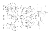
- Fig. 1 shows a co-rotating twin screw extruder 10 with an extruder barrel 14 comprising a mixing barrel 16.
- Two shafts to rotate conveying screws inside the extruder barrel and kneading disks inside the mixing barrel 16 are driven by a gear and motor box 12 of the twin screw extruder 10.
- the twin screw extruder 10 further has a hopper 18 for receiving polymer material 20 that is conveyed through the extruder barrel 14 and mixing barrel 16 into the direction of a die 22.
- Within the mixing barrel 16 several kneading disks are mixing the polymer material 20 which may comprise of a first and second material with different molecular weight and/or mineral filler and/or a colour masterbatch.
- Fig. 2 shows a cross-section of the twin screw extruder 10 along the line 2-2 of Fig. 1 .
- Fig. 2 shows a cross-section of the twin screw extruder 10 along the line 2-2 of Fig. 1 .
- the barrel 16 is formed of two cylindrical elements housing the kneading blocks comprising the two kneading disks 24, 24'.
- the kneading disk 24 has a hole 25 for receiving a shaft 26 of the twin screw extruder 10 and has a first lobe 28 and a second lobe 30 extending radially from the axis of rotation A. Also the second kneading disk 24' comprises a hole 25' for receiving a shaft 26' of the twin screw extruder 10 and also has two lobes 28', 30'.
- the kneading disk 24, at its radial ends of the lobes 28, 30, has two crest surfaces 32 that are tapered with respect to the inner surface 34 of the barrel 16.
- the kneading disk 24' only has a tapered crest surface 32 at the first lobe 28'.
- the other lobe 30' has a crest surface 32' that is not tapered but extends substantially parallel to the inner surface 34 of the barrel 16.
- a tapered gap or clearance 34 is formed between the crest surface 32 and the inner surface 34.
- Figs. 3A, 3B and 3C show a further embodiment of a kneading disk that is mirror-symmetric to the kneading disk 24 shown in Fig. 2 .
- Fig. 3A is a view of a kneading disk 24 in the direction of the axis of rotation A.
- Fig. 3B is a view onto the kneading disk of Fig. 3A into the direction of the arrow 3B in Fig. 3A.
- Fig. 3C is a view on top of the kneading disk 24 shown in Fig. 3A and Fig. 3B in the direction of the arrow 3C in Fig. 3A and 3B , respectively.
- the crest surface 32 is limited by a first edge 36, a second edge 38, a third edge 40 and a fourth edge 42.
- the edges 36 and 40 have a distance d 1 from the axis of rotation A.
- a corner 44 of the crest surface 32 has a minimal distance d 2 to the axis of rotation R.
- the radial distance d 1 may be 20 mm and the radial distance d 2 may be 18 mm.
- the gap or clearance 32 is on one end 2 mm wider than on the other end.
- other dimensions are possible too, for example the dimensions may be scaled.
- the kneading disk 24 is further limited by two axial side surfaces 46 that are extending orthogonal to the axis of rotation A and two radial side surfaces 48 that are approaching each other when getting distant from the axis of rotation A.
- the first edge 36 and the third edge 40 are also edges of the radial side surfaces 48, the second edge 38 and the fourth edge 42 are also edges of the axial side surfaces 46.
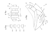
- Fig. 4 shows how the polymer melt flows through a kneading disk 24. Due to the tapered crest surface 32, the polymer material 20 inside the barrel 16 is subjected to an elongational rotational flow K in an (anti-)rotational direction and elongational axial flow T in the axial direction.
- the kneading block 50 shown in Fig. 4 comprises two adjacent kneading disks 24 that have a stagger angle W with respect to each other of 45°. Further the two kneading disks 24 have a width S that may be 11 mm for example.
- the flow T of the polymer material inside the screw extruder 10 in the axial direction is created by the screws of the screw extruder 10.
- the axial flow T in the axial direction is a flow towards the extruder die 22.
- the axial flow M in the opposite direction is towards the hopper 18 and is essential for distributive mixing of the polymer material.
- the flow K of the material 20 in the rotational direction opposite to the direction of rotation R of the kneading disks 24 may be caused by the rotation of the kneading disks 24.
- the crest surface 32 is also tapered in the rotational direction, the polymer material 20 inside the clearance 34, which is formed by the crest surface 32 and the inner surface 34 of the barrel 16, is subjected to a converging flow which results in a dispersive mixing of the polymer material 20.
- the width S of the kneading disks 24 is enlarged, the mixing action due to the flow M and the transport ability of the kneading block 50 due to the flow T is reduced. However, in this case the kneading action of the kneading disks 24 due to the flow K is enlarged.
- Fig. 5 shows a further embodiment of a kneading block 50.
- the kneading block 50 comprises four kneading disks 24 in sequence which are arranged on a shaft 26 with a stagger angle W of 90°.
- the sequence of kneading disks 24 with tapered crest surfaces 32 is limited by two kneading disks 24" with non-tapered crest surfaces 32', which may be formed like the crest surface 32' of the second lobe 30' of the kneading disk 24' of Fig. 2 .
- Fig. 6 shows a flow diagram of a method of mixing a first material and a second material with a screw extruder 10 as shown in Fig. 1 .
- a first material and a second material 20 are put into the hopper 18 of the screw extruder 10 and conveyed to the barrel 16 by a screw of the screw extruder 10.
- a step S12 the first material and the second material are mixed inside the barrel 16 by rotating disks 24 on kneading blocks 50 as shown, for example, in Fig. 4 and Fig. 5 .
- a step S 14 the polymer material formed of the first and the second material is compressed and extended inside the barrel 16 due to tapered crest surfaces 32.
- a step S16 the mixed first and second materials are conveyed to the die 22.
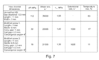
- Fig. 7 shows a table with calculations of the shear rate, the shear stress ⁇ w , the pressure drop ⁇ P, and the temperature rise in the clearance gap of a conventional kneading disk with non-tapered crest surfaces and a modified two-lobe kneading disk with tapered crest surfaces.
- the calculations are based on a uni-axial flow between parallel plates for the unmodified kneading disk or on a tapered slit for the modified kneading disk under adiabatic conditions and only concerning the pressure-driven flow in one of the clearances between a single kneading disk and the barrel in direction of the extruder die.
- the pressure drop and the temperature rise is much lower than in the case of an unmodified kneading disk with non-tapered crest surfaces.
- the pressure drop and the temperature rise are much higher compared to the reduction of the shear rate and the shear stress and therefore, the mixing of the polymer material inside the screw extruder with the modified kneading disks is nearly as high as in a screw extruder with unmodified conventional kneading disks but the degradation of the polymer material is much smaller.
Landscapes
- Engineering & Computer Science (AREA)
- Mechanical Engineering (AREA)
- Processing And Handling Of Plastics And Other Materials For Molding In General (AREA)
Abstract
Description
- The invention relates to the field of polymer extrusion. In particular, the invention relates to a kneading disk for a screw extruder, a screw extruder, a use of a kneading disk for a screw extruder and a method of mixing a first material and a second material with a screw extruder.
- Screw extrusion may be used for mixing, compounding or reacting polymeric materials, like, for example, polyethylene or dough for noodles. The polymer material may be placed into a hopper of a screw extruder which has at least one screw for conveying the polymer material into the direction of a die. A screw extruder may have a special mixing means in the path of the conveyed material. The mixing means is adapted for mixing the polymer material, for example in the case, when the polymer material comprises two or more components. Such mixing means may be a barrel in which at least one kneading disk is rotating. The at least one kneading disk may be driven by the same shaft which drives the screw for conveying the polymer material.
- Screw extruders may have only one screw. But there are screw extruders with two three or even more screws, which may be aligned parallel.
- In a twin screw extruder two parallel aligned screws are conveying the polymer material to the die. Also a twin screw extruder may have special mixing means with kneading disks. Twin screw extruders can further be categorized into co-rotating machines with both screws rotating in the same direction, and counter-rotating machines. Kneading disks are typically applied in co-rotating twin screw extruders.
- Screw extruders and kneading disks with different designs are for example known from
US 6 116 770 ,US 6 170 975 ,US 5 487 602 andDE 299 01 899 U1 . - However, the processing of polymer materials having a bi- or multimodal molecular weight distribution, for example, when the polymer material comprises polymer compounds with different molecular weights, may be accompanied by problems in dispersion and homogenization of the high molecular weight fraction within the low molecular weight continuous phase, especially on a co-rotating twin screw extruder. A poor homogenization may result in product inconsistency, fluctuation of processing parameters, gels and deterioration of mechanical properties. This may be due to a very high viscosity ratio. Additionally, shear within a polymer material may be very ineffective for mixing polymers having a viscosity ratio of more than 4.
- In order to get efficient dispersion of the minor high viscous component, elongational flow passages may be created in the processing equipment, in particular inside the barrel containing the kneading disks. In a co-rotating twin screw extruder this may be achieved by using a kneading block (an arrangement of at least two kneading disks on a shaft).
- However, the using of a dispersive kneading block with high shear may lead to excessive shear and degradation of the polymer material. Such degradation may be due to chain scission of long polymer chains, which may occur because of excessive viscous heating in clearances between the kneading disks and the extruder barrel. For example, there may be a more than 50 to 100 times higher shear rate in the flight clearance than in the extruder channel.
- The object of the present invention is to provide a screw extruder that is adapted to effectively mix polymers without degrading the polymers.
- This object is solved by the subject-matter of the independent claims. Exemplary embodiments of the invention are evident from the dependent claims.
- A first aspect relates to a kneading disk for a screw extruder, in particular a twin screw extruder, preferably a co-rotating twin screw extruder.
- According to an embodiment of the invention, the kneading disk has at least one lobe extending radially from an axis of rotation of the kneading disk. For example, the kneading disk may be placed on a shaft of the screw extruder, which may also rotate the screw of the screw extruder for conveying the polymer material. The shaft and therefore the kneading disk and also the screw may be rotated around the axis of the rotation.
- The kneading disk may be adapted for rotating inside a barrel of the screw extruder about the axis of rotation.
- According to an embodiment of the invention, the lobe has a crest surface limited by a first edge, a second edge opposite to the first edge, a third edge connecting the first edge and the second edge, and a fourth edge connecting the first edge and the second edge. When the kneading disk is situated inside the extruder barrel of the screw extruder, the crest surface faces an inner wall of the extruder barrel. A gap or clearance may be formed between the crest surface and the inner wall of the barrel. When the kneading disk is rotating, polymer material is flowing inside this gap or clearance.
- When looking onto the kneading disk in the direction the lobe extends radially from the axis of rotation, the crest surface may be a polygon with four edges. The crest surface may be a continuous, for example flat, surface that is limited by the first, second, third and fourth edge.
- According to an embodiment of the invention, the first edge extends parallel to the axis of rotation, wherein the first edge has a first radial distance to the axis of rotation. For example, the first edge may be a straight line extended parallel to the axis of rotation.
- According to an embodiment of the invention, the third edge extends in a rotational direction at the radial distance to the axis of rotation. For example, the third edge may be a circle segment of a circle around the axis of rotation with a radius equal to the radial distance of the first edge.
- According to an embodiment of the invention, substantially all of the crest surface is tapered towards a minimal point at which the second edge and the fourth edge meet, the minimal point having a smaller distance to the axis of rotation than the radial distance. For example, the second and/or the fourth edge may be continuous or may be formed of continuous parts connecting the first or third edge, respectively, with the minimal point. A continuous part may be straight or bent line.
- It has to be understood, that the crest surface may then be tapered, when it is not situated on a cylinder around the axis of rotation. This may mean that the second edge and fourth edge are approaching the minimal point which has a distance smaller to the axis of rotation than the first and third edge. The crest surface may be bent from the first edge and the third edge towards the minimal point, but, however may also be a flat surface.
- The kneading disk may have the tapered crest surface for improving dispersive mixing and/or lowering the degradation of polymer material inside the screw extruder. The tapered crest surface and the inner surface of the barrel may have a crest angle with respect to each other, for example an angle from 3° to 10°.
- The crest surface may be curved, when moving from a point on the first and/or third edge towards the minimal point.
- A kneading disk according to an embodiment of the invention may be formed by slightly modifying a crest surface or crest surfaces of a conventional kneading disk. For example, the crest surfaces according to the invention may be formed by cutting crest surfaces of a kneading disk that are parts of a cylinder surrounding the axis of rotation. In other words, the crest surfaces of a conventional kneading disk may be machined away until a crest surface according to an embodiment of the invention is formed.
- Modifying the crest surface in this way or forming the crest surface in this way results in opening the clearance between the kneading disk and the extruder barrel and, in the case of a screw extruder with more than one screw, for example a twin screw extruder, like a co-rotating twin screw extruder, the apex side of the opposite kneading disk. The polymer melt may be forced to pass through converging channels (formed by the clearance or the gap) which may extend in axial and/or tangential directions. A polymer melt may experience extensional deformation and/or stretching during drag and/or pressure flow in the clearance and expansion-relaxation when it is pumped to the next converging passage. On the other hand, the increased channel depth may reduce the temperature rise due to viscous dissipation.
- Further, the design according to the embodiments of the invention may not worsen the self wiping abilities of the screw extruder. There may be still wiping surface that has not been machined or that has the radial distance to the axis of rotation over the complete width of the kneading disk. In particular, the first edge may wipe the inner surface of the extruder barrel.
- According to an embodiment of the invention, the second edge and/or the fourth edge are approaching the axis of rotation towards the minimal point. In other words, the crest surface of the kneading disk is limited by at least two edges that are approaching the minimal point for forming a gap or clearance between the kneading disk and the inner surface of the barrel, when the kneading disk is installed inside a screw extruder.
- According to an embodiment of the invention, the second edge and/or the fourth edge, except in one end point, have a distance to the axis of rotation that is smaller than the radial distance. This may make it possible to have a crest surface that only has the maximal radial distance to the axis of rotation in two edges, i.e. in the first and third edge. All of the crest surface except the first and third edge may be less distant to the axis of rotation.
- According to an embodiment of the invention, the crest surface, except at the first edge and the third edge, has a distance to the axis of rotation that is smaller than the radial distance.
- According to an embodiment of the invention, the second edge and/or the fourth edge and/or the crest surface are declining continuously towards the minimal point. In this case, when the kneading disk is installed inside the extruder barrel of a screw extruder, a continuous gap or clearance is formed such that is continuously decreasing in one direction with respect to the axis or rotation.
- According to an embodiment of the invention, the kneading disk has a central section with a mounting bore for mounting the kneading disk to a shaft of the screw extruder. For example, the central section of the kneading disk may have a hole for mounting the kneading disk on a shaft of the screw extruder.
- According to an embodiment of the invention, the kneading disk has axial side surfaces extending parallel to the rotational direction and radial side surfaces extending parallel to the axis of rotation and approaching each other in a radial direction. By approaching each other in a radial direction, the radial surfaces and the axial side surfaces may limit the crest surface at the end of the lobe. As a rule, the crest surface may extend nearly parallel to the cylinder surrounding the axis of rotation, wherein the axial side surfaces and radial side surfaces may extend nearly parallel to the direction in which the lobe extends from the central section of the kneading disk.
- Generally, the kneading disk may be formed substantially as a body formed like an ellipse. In this case, two lobes may extend from the central section of the kneading disk.
- According to an embodiment of the invention, the lobe is a first lobe and the kneading disk has a second lobe. The first and second lobes may extend in different or opposite radial directions.
- A kneading disk may substantially have a rotational symmetry. However, the second lobe may be tapered differently or may be formed like a conventional lobe with a conventional crest surface.
- According to an embodiment of the invention, the second lobe has a crest surface that is not tapered. For example, the second crest surface may be a cylinder segment with a radial distance like the first and third edge of the first crest surface of the first lobe.
- According to an embodiment of the invention, the second lobe has a crest surface that is tapered like the crest surface of the first lobe.
- A further aspect to the invention relates to a screw extruder, for example a twin screw extruder, preferably a co-rotating twin screw extruder.
- According to an embodiment of the invention, the screw extruder comprises at least one shaft, for example two shafts in the case of a twin screw extruder, at least one kneading disk adapted to be rotated by the shaft and a barrel accommodating the at least one kneading disk. The screw extruder may further comprise a screw that is also accommodated in the barrel, wherein the screw may be used for conveying a polymer material from a hopper to a die.
- According to an embodiment of the invention, the screw extruder is adapted to transport a material through the barrel, the material to be mixed by the at least one kneading disk.
- According to an embodiment of the invention, the at least one kneading disk comprises a lobe with a crest surface, wherein the crest surface faces an inner surface of the barrel.
- According to an embodiment of the invention, a clearance is formed between the crest surface and the inner surface of the barrel, wherein the crest surface is tapered such that the clearance is converging or widening over nearly almost the crest surface in a rotational direction.
- According to an embodiment of the invention, the crest surface is tapered such that the clearance is widening or converging over nearly almost the crest surface in an axial direction. The axial direction may be defined by the at least one shaft or the two shafts extending parallel in the case of a twin screw extruder one of which is rotating the kneading disk in a direction of rotation. A material, for example polymer blend or compound, entering the clearance between the crest surface and the inner surface of the barrel may be conveyed through the clearance and may be pushed in a direction parallel to the axis of rotation and/or a direction parallel to the axis of rotation.
- According to an embodiment of the invention, the crest surface is tapered such that the material inside the clearance is extended or compressed, when the at least one kneading disk is rotated. If the first edge is the leading edge with respect to the rotation of the kneading disk, the clearance or gap may be widening in the direction of rotation and the material inside the clearance may be extended due to the rotation of the kneading disk. When the first edge is a trailing edge with respect to the direction of rotation, the clearance is converging in the direction of rotation and the material inside the clearance may be compressed, when the at least one kneading disk is rotating.
- According to an embodiment of the invention, the crest surface may not only be tapered in the direction of rotation but also may be tapered in the axial direction. Thus, when the kneading disk is rotating, the material inside the clearance may also be conveyed in a direction parallel to the axis of rotation and therefore, the kneading disk may pump or convey the polymer material inside the barrel either in the direction to the die or in the direction to the hopper.
- According to an embodiment of the invention, the at least one kneading disk of the screw extruder may be a kneading disk as described in the above and in the following.
- A further aspect of the invention relates to a use of a kneading disk as described in the above and in the following for a screw extruder for mixing plastic material having a bimodal or multimodal molecular weight distribution.
- A further aspect of the invention relates to a method of mixing a first material and a second material with a screw extruder. The first material and the second material may have different molecular weight distributions but may alternatively or additionally comprise a polymer, a mineral filler and/or a colour masterbatch. The kneading disk according to an embodiment of the invention may also better disperse carbon black masterbatches compared to a conventional kneading block and may also help to disperse of mineral fillers in polymeric matrices. In these cases elongational flow as provided by a kneading block according to an embodiment of the invention may be needed for destroying filler agglomerates.
- According to an embodiment of the invention, the method comprises the steps of: conveying the first material and the second material to a barrel of the screw extruder containing at least one kneading disk. For example, this may be done with at least one screw of the screw extruder.
- According to an embodiment of the invention, the method comprises the step of: mixing the first material and the second material by rotating the at least one kneading disk. As already explained, due to the tapered crest surface, a clearance is formed between the kneading disk and the inner surface of the barrel and the materials inside the barrel are extended or compressed inside the clearance, resulting in a dispersive mixing of the first and second material.
- According to an embodiment of the invention, the method comprises the step of: compressing or extending the first material and the second material inside a clearance between a crest surface of a lobe of the kneading disk and an inner surface of the barrel by rotating the kneading disk, wherein the crest surface is tapered such that the clearance is converging or widening over nearly almost the crest surface in a rotational direction.
- A further aspect to the invention relates to a kneading block formed of at least two kneading disks. At least one of the kneading disks of the kneading block may be a kneading disk as described in the above and in the following. At least one of the kneading disks may be a conventional kneading disk or for example a kneading disk comprising a cylindrical crest surface.
- Combining the modified kneading disk with at least one conventional kneading disk with a non-tapered crest surface in sequence or combining several modified kneading disks as described in the above and in the following in sequence may provide flexibility and a further additional degree of freedom when designing two extruders for specific products and purposes. For example, four kneading disks with tapered crest surfaces may be arranged in sequence on the shaft of the screw extruder, wherein the kneading disks are staggered in either a 30°, 45° or a 90° stagger angle. Further it may be possible, that an arrangement of kneading disks with tapered surfaces is limited by one or two kneading disks with conventional non-tapered surfaces. Also in this case, the kneading disks may be staggered at 30°, 45° or 90°.
- To summarize, increasing the clearance by achieving a specific angle between the crest surface and the inner surface of the barrel may create an elongational flow passage, which will improve the dispersive mixing. When the crest surface is tapered in two directions, i.e. in the direction of rotation and in the axial direction, the elongational flow may be in the radial and the tangential direction. Further, the distributive mixing may not be compromised, since the wall shear stress/rate does not change much. Further the pumping ability may not be influenced, since no change of the trailing flight height occurs. However, there may be a huge reduction of the temperature rise due to viscous heating, which in turn may result in a polymer melt having more homogeneous temperature distribution. Further, the flexibility of the design of the screw extruder is enhanced. For example, the extensional rate may be easily altered by changing the conversion angles which may also open up flow channels and/or by changing the arrangement of kneading disks of a kneading block.
- These and other aspects of the invention will be apparent from and elucidated with reference to the embodiment described hereinafter.
- Below, embodiments of the present invention are described in more detail with reference to the attached drawings.
-
Fig. 1 shows a schematic diagram of a co-rotating twin screw extruder according to an embodiment of the invention. -
Fig. 2 shows a cross-section of the co-rotating twin screw extruder ofFig. 1 along the line 2-2, according to an embodiment of the invention. -
Fig. 3A, 3B and 3C show a kneading disk from three different directions according to an embodiment of the invention. -
Fig. 4 schematically shows the polymer flow inside an extruder barrel according to an embodiment of the invention. -
Fig. 5 shows a kneading block according to an embodiment of the invention. -
Fig. 6 shows a flow diagram for a method of mixing a first material and a second material according to an embodiment of the invention. -
Fig. 7 shows a table with calculated data for different dimensions of the flow channel between a kneading block and the extruder barrel according to an embodiment of the invention. - The reference symbols used in the figures, and their meanings, are listed in summary form in the list of reference symbols. In principle, similar or identical parts are provided with the same reference symbols in the figures.
-
Fig. 1 shows a co-rotatingtwin screw extruder 10 with anextruder barrel 14 comprising a mixingbarrel 16. Two shafts to rotate conveying screws inside the extruder barrel and kneading disks inside the mixingbarrel 16 are driven by a gear andmotor box 12 of thetwin screw extruder 10. Thetwin screw extruder 10 further has ahopper 18 for receivingpolymer material 20 that is conveyed through theextruder barrel 14 and mixingbarrel 16 into the direction of adie 22. Inside the mixingbarrel 16 several kneading disks are mixing thepolymer material 20 which may comprise of a first and second material with different molecular weight and/or mineral filler and/or a colour masterbatch. -
Fig. 2 shows a cross-section of thetwin screw extruder 10 along the line 2-2 ofFig. 1 . As can be seen fromFig. 2 , inside thebarrel 16, two kneadingdisks 24, 24' are rotating in a direction of rotation R. Thebarrel 16 is formed of two cylindrical elements housing the kneading blocks comprising the two kneadingdisks 24, 24'. - The
kneading disk 24 has ahole 25 for receiving ashaft 26 of thetwin screw extruder 10 and has afirst lobe 28 and asecond lobe 30 extending radially from the axis of rotation A. Also the second kneading disk 24' comprises a hole 25' for receiving a shaft 26' of thetwin screw extruder 10 and also has two lobes 28', 30'. Thekneading disk 24, at its radial ends of thelobes crest surfaces 32 that are tapered with respect to theinner surface 34 of thebarrel 16. - The kneading disk 24' only has a tapered
crest surface 32 at the first lobe 28'. The other lobe 30' has a crest surface 32' that is not tapered but extends substantially parallel to theinner surface 34 of thebarrel 16. - Due to the tapered
surface 32, a tapered gap orclearance 34 is formed between thecrest surface 32 and theinner surface 34. When the kneading disks are rotating in the direction of rotation R, theplastic material 20 inside thebarrel 16 is compressed inside the gap orclearance 34. -
Figs. 3A, 3B and 3C show a further embodiment of a kneading disk that is mirror-symmetric to thekneading disk 24 shown inFig. 2 . -
Fig. 3A is a view of akneading disk 24 in the direction of the axis of rotation A.Fig. 3B is a view onto the kneading disk ofFig. 3A into the direction of thearrow 3B inFig. 3A. Fig. 3C is a view on top of thekneading disk 24 shown inFig. 3A and Fig. 3B in the direction of thearrow 3C inFig. 3A and 3B , respectively. - As can be seen best in
Fig. 3C , thecrest surface 32 is limited by afirst edge 36, asecond edge 38, athird edge 40 and afourth edge 42. Theedges corner 44 of thecrest surface 32 has a minimal distance d2 to the axis of rotation R. The radial distance d1 may be 20 mm and the radial distance d2 may be 18 mm. In this case, the gap orclearance 32 is on oneend 2 mm wider than on the other end. However, it has to be noted that other dimensions are possible too, for example the dimensions may be scaled. Thekneading disk 24 is further limited by two axial side surfaces 46 that are extending orthogonal to the axis of rotation A and two radial side surfaces 48 that are approaching each other when getting distant from the axis of rotation A. Thefirst edge 36 and thethird edge 40 are also edges of the radial side surfaces 48, thesecond edge 38 and thefourth edge 42 are also edges of the axial side surfaces 46. -
Fig. 4 shows how the polymer melt flows through akneading disk 24. Due to the taperedcrest surface 32, thepolymer material 20 inside thebarrel 16 is subjected to an elongational rotational flow K in an (anti-)rotational direction and elongational axial flow T in the axial direction. The kneadingblock 50 shown inFig. 4 comprises twoadjacent kneading disks 24 that have a stagger angle W with respect to each other of 45°. Further the two kneadingdisks 24 have a width S that may be 11 mm for example. As a rule, the flow T of the polymer material inside thescrew extruder 10 in the axial direction is created by the screws of thescrew extruder 10. The axial flow T in the axial direction is a flow towards the extruder die 22. The axial flow M in the opposite direction is towards thehopper 18 and is essential for distributive mixing of the polymer material.
The flow K of the material 20 in the rotational direction opposite to the direction of rotation R of the kneadingdisks 24 may be caused by the rotation of the kneadingdisks 24. Since thecrest surface 32 is also tapered in the rotational direction, thepolymer material 20 inside theclearance 34, which is formed by thecrest surface 32 and theinner surface 34 of thebarrel 16, is subjected to a converging flow which results in a dispersive mixing of thepolymer material 20. - There are several relations between these variables. If the stagger angle W is enlarged, the mixing action of the kneading
block 50 due to the flow M is also enlarging. However, in this case, the axial flow T in the axial direction, i.e. the transport of polymer material in the direction to the extruder die is reduced. - If the width S of the kneading
disks 24 is enlarged, the mixing action due to the flow M and the transport ability of the kneadingblock 50 due to the flow T is reduced. However, in this case the kneading action of the kneadingdisks 24 due to the flow K is enlarged. -
Fig. 5 shows a further embodiment of a kneadingblock 50. The kneadingblock 50 comprises four kneadingdisks 24 in sequence which are arranged on ashaft 26 with a stagger angle W of 90°. The sequence of kneadingdisks 24 with tapered crest surfaces 32 is limited by two kneadingdisks 24" with non-tapered crest surfaces 32', which may be formed like the crest surface 32' of the second lobe 30' of the kneading disk 24' ofFig. 2 . -
Fig. 6 shows a flow diagram of a method of mixing a first material and a second material with ascrew extruder 10 as shown inFig. 1 . - In a step S10, a first material and a
second material 20 are put into thehopper 18 of thescrew extruder 10 and conveyed to thebarrel 16 by a screw of thescrew extruder 10. - In a step S12, the first material and the second material are mixed inside the
barrel 16 by rotatingdisks 24 on kneadingblocks 50 as shown, for example, inFig. 4 and Fig. 5 . - In a
step S 14, the polymer material formed of the first and the second material is compressed and extended inside thebarrel 16 due to tapered crest surfaces 32. - In a step S16, the mixed first and second materials are conveyed to the
die 22. -
Fig. 7 shows a table with calculations of the shear rate, the shear stress τw, the pressure drop ΔP, and the temperature rise in the clearance gap of a conventional kneading disk with non-tapered crest surfaces and a modified two-lobe kneading disk with tapered crest surfaces. The calculations are based on a uni-axial flow between parallel plates for the unmodified kneading disk or on a tapered slit for the modified kneading disk under adiabatic conditions and only concerning the pressure-driven flow in one of the clearances between a single kneading disk and the barrel in direction of the extruder die. Rheological data for a conventional HDPE (for example the power-law parameters m, n and the heat capacity) at temperature of 200°C have been taken. The screw channel dimensions of a ZSK-40 two-lobe kneading block are implied in the calculations and it is assumed that the extruder operates at 100 kg/h throughput rate. - For the unmodified kneading disk a gap clearance of 0.3 mm between the crest surface and the inner surface of the barrel has been assumed. The calculations have been performed for a crest surface with a width of 7 mm and a length of 11 mm.
- For a first modified kneading disk with a tapered crest surface, an entry gap of 1 mm and an exit gap of 0.3 mm have been taken for the calculation. Due to the different gaps between the entry and the exit of the flowing material, a conversion angle of 4° between the crest surface and the inner surface of the barrel is formed.
- For the second embodiment of a modified kneading disk with tapered crest surface a bigger gap of 1.5 mm at the entry has been taken for the calculation. Due to this a conversion angle of 6° is formed between the crest surface and the inner surface of the barrel.
- As can be derived from the table, with the modified kneading disks, the pressure drop and the temperature rise is much lower than in the case of an unmodified kneading disk with non-tapered crest surfaces. However, the pressure drop and the temperature rise are much higher compared to the reduction of the shear rate and the shear stress and therefore, the mixing of the polymer material inside the screw extruder with the modified kneading disks is nearly as high as in a screw extruder with unmodified conventional kneading disks but the degradation of the polymer material is much smaller.
- While the invention has been illustrated and described in detail in the drawings and foregoing description, such illustration and description are to be considered illustrative or exemplary and not restrictive; the invention is not limited to the disclosed embodiments. Other variations to the disclosed embodiments can be understood and effected by those skilled in the art and practising the claimed invention, from a study of the drawings, the disclosure, and the appended claims. In the claims, the word "comprising" does not exclude other elements or steps, and the indefinite article "a" or "an" does not exclude a plurality. A single processor or controller or other unit may fulfil the functions of several items recited in the claims. The mere fact that certain measures are recited in mutually different dependent claims does not indicate that a combination of these measures cannot be used to advantage. Any reference signs in the claims should not be construed as limiting the scope.
-
- 10
- twin screw extruder
- 12
- gear and motor box
- 14
- extruder barrel
- 16
- mixing barrel
- 18
- hopper
- 20
- polymer material
- 22
- die
- 24, 24', 24"
- kneading disk
- R
- rotational direction
- 25, 25'
- hole
- 26, 26'
- shaft
- A
- axis of rotation
- 28, 28'
- first lobe
- 30, 30'
- second lobe
- 32, 32'
- crest surface
- 34
- gap/clearance
- 36
- first edge
- 38
- second edge
- 40
- third edge
- 42
- forth edge
- 44
- minimal point
- 46
- axial side surface
- 48
- radial side surface
- K
- radial flow
- T, M
- axial flow
- 50, 50'
- kneading block
Claims (15)
- A kneading disk (24) for a screw extruder (10)
having at least one lobe (28) extending radially from an axis of rotation (A) of the kneading disk (24);
wherein the lobe (28) has a crest surface (32) limited by a first edge (36), a second edge (38) opposite to the first edge (36), a third edge (40) connecting the first edge (36) and the second edge (38), and a forth edge (42) connecting the first edge (36) and the second edge (38);
wherein the first edge (36) extends parallel to the axis of rotation (A), the first edge (36) having a first radial distance (d1) to the axis of rotation (A);
wherein the third edge (40) extends in a rotational direction (R) at the radial distance (d1) to the axis of rotation (R);
wherein substantially all of the crest surface (32) is tapered towards a minimal point (44) at which the second edge (38) and the forth edge (42) meet, the minimal point (44) having a smaller distance (d2) to the axis of rotation (A) than the radial distance (d1). - The kneading disk (24) of claim 1,
wherein the second edge (38) and/or the forth edge (42) are approaching the axis of rotation (A) towards the minimal point (44). - The kneading disk (24) of claim 1 or 2,
wherein the second edge (38) and/or the forth edge (42), except in one end point, have a distance to the axis of rotation (A) that is smaller than the radial distance (d1). - The kneading disk (24) of one of the preceding claims,
wherein the crest surface (32), except at the first edge (36) and the third edge (40), has a distance to the axis of rotation that is smaller than the radial distance (d1). - The kneading disk (24) of one of the preceding claims,
wherein the second edge (38) and/or the forth edge (42) and/or the crest surface (32) are declining continuously towards the minimal point (44). - The kneading disk (24) of one of the preceding claims,
wherein the lobe is a first lobe (28);
wherein the kneading disk has a second lobe (30);
wherein the first and second lobes are extending in opposite radial directions. - The kneading disk (24') of claim 6,
wherein the second lobe (30') has a second crest surface (32') that is not tapered. - The kneading disk (24) of claim 6,
wherein the second lobe (30) has a crest surface (32) that is tapered like the crest surface of the first lobe (28). - A screw extruder (10), comprising:at least one shaft (26);at least one kneading disk (24) adapted to be rotated by the shaft (26);a barrel (16) accommodating the at least one kneading disk (24);wherein the screw extruder (10) is adapted to transport a material (20) through the barrel (16), the material (20) to be mixed by the at least one kneading disk (24);wherein the at least one kneading disk (24) comprises a lobe (28) with a crest surface (32), the crest surface (32) facing an inner surface (34) of the barrel (16);wherein a clearance (34) is formed between the crest surface (32) and the inner surface (34) of the barrel (16),wherein the crest surface (32) is tapered such that the clearance (34) is converging or widening over nearly almost the crest surface (32) in a rotational direction (R).
- The screw extruder (10) according to claim 9,
wherein the crest surface (32) is tapered such that the clearance is widening or converging over nearly almost the crest surface (32) in an axial direction (A). - The screw extruder (10) according to claim 9 or 10,
wherein the crest surface (32) is tapered such that the material (20) inside the clearance is extended or compressed, when the at least one kneading disk (24) is rotated. - The screw extruder (10) according to one of the claims 9 to 11,
wherein the least one kneading disk is a kneading disk (32) according to one of the claims 1 to 8. - A use of a kneading disk (24) according to claims 1 to 8 for a screw extruder (10) for mixing plastic material having a bimodal molecular weight distribution.
- A method of mixing a first material and a second material with a screw extruder, the method comprising the steps of:conveying the first material and the second material to a barrel of the screw extruder containing at least one kneading disk;mixing the first material and the second material by rotating the at least one kneading disk;compressing or extending the first material and the second material inside a clearance between a crest surface of a lobe of the kneading disk and an inner surface of the barrel by rotating the kneading disk, wherein the crest surface is tapered such that the clearance is converging or widening over nearly almost the crest surface in a rotational direction.
- A kneading block (50), comprising:at least one kneading disk (24) according to one of the claims 1 to 8;at least one kneading disk (24") comprising a cylindrical crest surface.
Priority Applications (1)
| Application Number | Priority Date | Filing Date | Title |
|---|---|---|---|
| EP10159622.9A EP2374600B1 (en) | 2010-04-12 | 2010-04-12 | Kneading disk with tapered crest surface |
Applications Claiming Priority (1)
| Application Number | Priority Date | Filing Date | Title |
|---|---|---|---|
| EP10159622.9A EP2374600B1 (en) | 2010-04-12 | 2010-04-12 | Kneading disk with tapered crest surface |
Publications (2)
| Publication Number | Publication Date |
|---|---|
| EP2374600A1 true EP2374600A1 (en) | 2011-10-12 |
| EP2374600B1 EP2374600B1 (en) | 2014-03-26 |
Family
ID=42697331
Family Applications (1)
| Application Number | Title | Priority Date | Filing Date |
|---|---|---|---|
| EP10159622.9A Not-in-force EP2374600B1 (en) | 2010-04-12 | 2010-04-12 | Kneading disk with tapered crest surface |
Country Status (1)
| Country | Link |
|---|---|
| EP (1) | EP2374600B1 (en) |
Cited By (2)
| Publication number | Priority date | Publication date | Assignee | Title |
|---|---|---|---|---|
| WO2015145271A1 (en) | 2014-03-28 | 2015-10-01 | Nova Chemicals (International) S.A. | Improved extrusion process for polyethylene polymers |
| US20220324152A1 (en) * | 2019-10-01 | 2022-10-13 | The Japan Steel Works, Ltd. | Resin extruder, rotor-type screw, and resin manufacturing method |
Citations (6)
| Publication number | Priority date | Publication date | Assignee | Title |
|---|---|---|---|---|
| US5487602A (en) | 1994-06-03 | 1996-01-30 | Farrel Corporation | Multi-screw, extrusion-compounding machine with modular mixing elements |
| EP0848988A2 (en) | 1996-12-19 | 1998-06-24 | KABUSHIKI KAISHA KOBE SEIKO SHO also known as Kobe Steel Ltd. | Enclosed kneading apparatus |
| DE29901899U1 (en) | 1999-02-04 | 1999-04-22 | Friedrich Theysohn Gmbh, 30853 Langenhagen | Twin screw extruder |
| US6116770A (en) | 1998-10-02 | 2000-09-12 | Krupp Werner & Pfleiderer Corporation | Mixing element for screw extruder |
| US6170975B1 (en) | 1999-02-08 | 2001-01-09 | Krupp Werner & Pfleiderer | Multi-shaft extruder kneading discs, kneading disc blocks and extruder |
| US20070177451A1 (en) * | 2006-02-02 | 2007-08-02 | Benjamin Craig A | Serrated kneading disk and kneading block |
-
2010
- 2010-04-12 EP EP10159622.9A patent/EP2374600B1/en not_active Not-in-force
Patent Citations (6)
| Publication number | Priority date | Publication date | Assignee | Title |
|---|---|---|---|---|
| US5487602A (en) | 1994-06-03 | 1996-01-30 | Farrel Corporation | Multi-screw, extrusion-compounding machine with modular mixing elements |
| EP0848988A2 (en) | 1996-12-19 | 1998-06-24 | KABUSHIKI KAISHA KOBE SEIKO SHO also known as Kobe Steel Ltd. | Enclosed kneading apparatus |
| US6116770A (en) | 1998-10-02 | 2000-09-12 | Krupp Werner & Pfleiderer Corporation | Mixing element for screw extruder |
| DE29901899U1 (en) | 1999-02-04 | 1999-04-22 | Friedrich Theysohn Gmbh, 30853 Langenhagen | Twin screw extruder |
| US6170975B1 (en) | 1999-02-08 | 2001-01-09 | Krupp Werner & Pfleiderer | Multi-shaft extruder kneading discs, kneading disc blocks and extruder |
| US20070177451A1 (en) * | 2006-02-02 | 2007-08-02 | Benjamin Craig A | Serrated kneading disk and kneading block |
Cited By (4)
| Publication number | Priority date | Publication date | Assignee | Title |
|---|---|---|---|---|
| WO2015145271A1 (en) | 2014-03-28 | 2015-10-01 | Nova Chemicals (International) S.A. | Improved extrusion process for polyethylene polymers |
| US10124527B2 (en) | 2014-03-28 | 2018-11-13 | Nova Chemicals (International) S.A. | Extrusion process for polyethylene polymers |
| US20220324152A1 (en) * | 2019-10-01 | 2022-10-13 | The Japan Steel Works, Ltd. | Resin extruder, rotor-type screw, and resin manufacturing method |
| US12539658B2 (en) * | 2019-10-01 | 2026-02-03 | The Japan Steel Works, Ltd. | Resin extruder , rotor-type screw shaped so that the size of the gap between the screw and the inner surface of the cylinder holding the screw changes, and resin manufacturing method |
Also Published As
| Publication number | Publication date |
|---|---|
| EP2374600B1 (en) | 2014-03-26 |
Similar Documents
| Publication | Publication Date | Title |
|---|---|---|
| JP5137613B2 (en) | Kneading disc segment and twin screw extruder | |
| JP4768018B2 (en) | Reverse rotation twin screw extruder | |
| TWI724404B (en) | Mixing method and mixture | |
| KR101205562B1 (en) | Kneading degree adjusting device, extruder and continuous kneader | |
| US11584830B2 (en) | Production method for conductive composite material | |
| KR101452653B1 (en) | Continuous kneading machine and kneading method | |
| KR101801414B1 (en) | Screw feed elements for extruding viscoelastic masses, and use and method | |
| EP2792462A1 (en) | Kneading segment | |
| US9090013B2 (en) | Dual screw extrusion apparatus having a mixing chamber and a conveying chamber downstream thereof with the mixing chamber having a wall clearance greater than that of the conveying chamber | |
| EP3915758A1 (en) | Screw and extruder | |
| TWI794305B (en) | Asymmetric three-bladed worm shaft for a mixing and kneading machine, section for such a worm shaft, housing containing the worm shaft, and corresponding mixing and kneading machine | |
| US9346190B2 (en) | Device for processing material by mixing and/or plasticating | |
| EP2374600B1 (en) | Kneading disk with tapered crest surface | |
| KR101704311B1 (en) | Kneading rotor and kneading machine | |
| CN101400500B (en) | Screw element | |
| KR20250002202A (en) | Multi-shaft screw machine comprising pairs of screw elements with improved mixing and degassing effect with reduced energy input | |
| KR20200126417A (en) | Kneading method and mixture | |
| US12539658B2 (en) | Resin extruder , rotor-type screw shaped so that the size of the gap between the screw and the inner surface of the cylinder holding the screw changes, and resin manufacturing method | |
| CN106956415A (en) | Combined double-rotor continuous mixing extruder | |
| JPH1158369A (en) | Twin screw continuous kneader | |
| JPH07148821A (en) | Screw element for screw type extruder and screw shaft arrangement with the screw element | |
| CN103429408B (en) | Continuous mixer | |
| US11027475B2 (en) | Screw-type extruder | |
| EP2517852A1 (en) | Segment for kneading, and kneading facility |
Legal Events
| Date | Code | Title | Description |
|---|---|---|---|
| PUAI | Public reference made under article 153(3) epc to a published international application that has entered the european phase |
Free format text: ORIGINAL CODE: 0009012 |
|
| 17P | Request for examination filed |
Effective date: 20101222 |
|
| AK | Designated contracting states |
Kind code of ref document: A1 Designated state(s): AT BE BG CH CY CZ DE DK EE ES FI FR GB GR HR HU IE IS IT LI LT LU LV MC MK MT NL NO PL PT RO SE SI SK SM TR |
|
| AX | Request for extension of the european patent |
Extension state: AL BA ME RS |
|
| RIC1 | Information provided on ipc code assigned before grant |
Ipc: B29C 47/40 20060101ALI20130823BHEP Ipc: B29C 47/64 20060101AFI20130823BHEP Ipc: B29C 47/60 20060101ALI20130823BHEP Ipc: B29C 47/38 20060101ALI20130823BHEP Ipc: B29B 7/48 20060101ALI20130823BHEP |
|
| 17Q | First examination report despatched |
Effective date: 20130925 |
|
| GRAP | Despatch of communication of intention to grant a patent |
Free format text: ORIGINAL CODE: EPIDOSNIGR1 |
|
| INTG | Intention to grant announced |
Effective date: 20131219 |
|
| GRAS | Grant fee paid |
Free format text: ORIGINAL CODE: EPIDOSNIGR3 |
|
| GRAA | (expected) grant |
Free format text: ORIGINAL CODE: 0009210 |
|
| AK | Designated contracting states |
Kind code of ref document: B1 Designated state(s): AT BE BG CH CY CZ DE DK EE ES FI FR GB GR HR HU IE IS IT LI LT LU LV MC MK MT NL NO PL PT RO SE SI SK SM TR |
|
| REG | Reference to a national code |
Ref country code: GB Ref legal event code: FG4D |
|
| REG | Reference to a national code |
Ref country code: CH Ref legal event code: EP |
|
| REG | Reference to a national code |
Ref country code: AT Ref legal event code: REF Ref document number: 658720 Country of ref document: AT Kind code of ref document: T Effective date: 20140415 |
|
| REG | Reference to a national code |
Ref country code: IE Ref legal event code: FG4D |
|
| REG | Reference to a national code |
Ref country code: DE Ref legal event code: R096 Ref document number: 602010014550 Country of ref document: DE Effective date: 20140508 |
|
| PG25 | Lapsed in a contracting state [announced via postgrant information from national office to epo] |
Ref country code: NO Free format text: LAPSE BECAUSE OF FAILURE TO SUBMIT A TRANSLATION OF THE DESCRIPTION OR TO PAY THE FEE WITHIN THE PRESCRIBED TIME-LIMIT Effective date: 20140626 Ref country code: LT Free format text: LAPSE BECAUSE OF FAILURE TO SUBMIT A TRANSLATION OF THE DESCRIPTION OR TO PAY THE FEE WITHIN THE PRESCRIBED TIME-LIMIT Effective date: 20140326 |
|
| REG | Reference to a national code |
Ref country code: NL Ref legal event code: VDEP Effective date: 20140326 |
|
| REG | Reference to a national code |
Ref country code: LT Ref legal event code: MG4D |
|
| PG25 | Lapsed in a contracting state [announced via postgrant information from national office to epo] |
Ref country code: FI Free format text: LAPSE BECAUSE OF FAILURE TO SUBMIT A TRANSLATION OF THE DESCRIPTION OR TO PAY THE FEE WITHIN THE PRESCRIBED TIME-LIMIT Effective date: 20140326 Ref country code: SE Free format text: LAPSE BECAUSE OF FAILURE TO SUBMIT A TRANSLATION OF THE DESCRIPTION OR TO PAY THE FEE WITHIN THE PRESCRIBED TIME-LIMIT Effective date: 20140326 |
|
| PG25 | Lapsed in a contracting state [announced via postgrant information from national office to epo] |
Ref country code: HR Free format text: LAPSE BECAUSE OF FAILURE TO SUBMIT A TRANSLATION OF THE DESCRIPTION OR TO PAY THE FEE WITHIN THE PRESCRIBED TIME-LIMIT Effective date: 20140326 Ref country code: LV Free format text: LAPSE BECAUSE OF FAILURE TO SUBMIT A TRANSLATION OF THE DESCRIPTION OR TO PAY THE FEE WITHIN THE PRESCRIBED TIME-LIMIT Effective date: 20140326 |
|
| PG25 | Lapsed in a contracting state [announced via postgrant information from national office to epo] |
Ref country code: CY Free format text: LAPSE BECAUSE OF FAILURE TO SUBMIT A TRANSLATION OF THE DESCRIPTION OR TO PAY THE FEE WITHIN THE PRESCRIBED TIME-LIMIT Effective date: 20140326 Ref country code: NL Free format text: LAPSE BECAUSE OF FAILURE TO SUBMIT A TRANSLATION OF THE DESCRIPTION OR TO PAY THE FEE WITHIN THE PRESCRIBED TIME-LIMIT Effective date: 20140326 Ref country code: BE Free format text: LAPSE BECAUSE OF FAILURE TO SUBMIT A TRANSLATION OF THE DESCRIPTION OR TO PAY THE FEE WITHIN THE PRESCRIBED TIME-LIMIT Effective date: 20140326 Ref country code: IS Free format text: LAPSE BECAUSE OF FAILURE TO SUBMIT A TRANSLATION OF THE DESCRIPTION OR TO PAY THE FEE WITHIN THE PRESCRIBED TIME-LIMIT Effective date: 20140726 Ref country code: RO Free format text: LAPSE BECAUSE OF FAILURE TO SUBMIT A TRANSLATION OF THE DESCRIPTION OR TO PAY THE FEE WITHIN THE PRESCRIBED TIME-LIMIT Effective date: 20140326 Ref country code: BG Free format text: LAPSE BECAUSE OF FAILURE TO SUBMIT A TRANSLATION OF THE DESCRIPTION OR TO PAY THE FEE WITHIN THE PRESCRIBED TIME-LIMIT Effective date: 20140626 Ref country code: CZ Free format text: LAPSE BECAUSE OF FAILURE TO SUBMIT A TRANSLATION OF THE DESCRIPTION OR TO PAY THE FEE WITHIN THE PRESCRIBED TIME-LIMIT Effective date: 20140326 Ref country code: EE Free format text: LAPSE BECAUSE OF FAILURE TO SUBMIT A TRANSLATION OF THE DESCRIPTION OR TO PAY THE FEE WITHIN THE PRESCRIBED TIME-LIMIT Effective date: 20140326 |
|
| PG25 | Lapsed in a contracting state [announced via postgrant information from national office to epo] |
Ref country code: SK Free format text: LAPSE BECAUSE OF FAILURE TO SUBMIT A TRANSLATION OF THE DESCRIPTION OR TO PAY THE FEE WITHIN THE PRESCRIBED TIME-LIMIT Effective date: 20140326 Ref country code: PL Free format text: LAPSE BECAUSE OF FAILURE TO SUBMIT A TRANSLATION OF THE DESCRIPTION OR TO PAY THE FEE WITHIN THE PRESCRIBED TIME-LIMIT Effective date: 20140326 Ref country code: MC Free format text: LAPSE BECAUSE OF FAILURE TO SUBMIT A TRANSLATION OF THE DESCRIPTION OR TO PAY THE FEE WITHIN THE PRESCRIBED TIME-LIMIT Effective date: 20140326 Ref country code: ES Free format text: LAPSE BECAUSE OF FAILURE TO SUBMIT A TRANSLATION OF THE DESCRIPTION OR TO PAY THE FEE WITHIN THE PRESCRIBED TIME-LIMIT Effective date: 20140326 |
|
| REG | Reference to a national code |
Ref country code: CH Ref legal event code: PL |
|
| PG25 | Lapsed in a contracting state [announced via postgrant information from national office to epo] |
Ref country code: PT Free format text: LAPSE BECAUSE OF FAILURE TO SUBMIT A TRANSLATION OF THE DESCRIPTION OR TO PAY THE FEE WITHIN THE PRESCRIBED TIME-LIMIT Effective date: 20140728 |
|
| REG | Reference to a national code |
Ref country code: DE Ref legal event code: R097 Ref document number: 602010014550 Country of ref document: DE |
|
| REG | Reference to a national code |
Ref country code: IE Ref legal event code: MM4A |
|
| PG25 | Lapsed in a contracting state [announced via postgrant information from national office to epo] |
Ref country code: DK Free format text: LAPSE BECAUSE OF FAILURE TO SUBMIT A TRANSLATION OF THE DESCRIPTION OR TO PAY THE FEE WITHIN THE PRESCRIBED TIME-LIMIT Effective date: 20140326 Ref country code: CH Free format text: LAPSE BECAUSE OF NON-PAYMENT OF DUE FEES Effective date: 20140430 Ref country code: LI Free format text: LAPSE BECAUSE OF NON-PAYMENT OF DUE FEES Effective date: 20140430 |
|
| PLBE | No opposition filed within time limit |
Free format text: ORIGINAL CODE: 0009261 |
|
| STAA | Information on the status of an ep patent application or granted ep patent |
Free format text: STATUS: NO OPPOSITION FILED WITHIN TIME LIMIT |
|
| 26N | No opposition filed |
Effective date: 20150106 |
|
| PG25 | Lapsed in a contracting state [announced via postgrant information from national office to epo] |
Ref country code: IT Free format text: LAPSE BECAUSE OF FAILURE TO SUBMIT A TRANSLATION OF THE DESCRIPTION OR TO PAY THE FEE WITHIN THE PRESCRIBED TIME-LIMIT Effective date: 20140326 |
|
| REG | Reference to a national code |
Ref country code: DE Ref legal event code: R097 Ref document number: 602010014550 Country of ref document: DE Effective date: 20150106 |
|
| PG25 | Lapsed in a contracting state [announced via postgrant information from national office to epo] |
Ref country code: IE Free format text: LAPSE BECAUSE OF NON-PAYMENT OF DUE FEES Effective date: 20140412 |
|
| PG25 | Lapsed in a contracting state [announced via postgrant information from national office to epo] |
Ref country code: SI Free format text: LAPSE BECAUSE OF FAILURE TO SUBMIT A TRANSLATION OF THE DESCRIPTION OR TO PAY THE FEE WITHIN THE PRESCRIBED TIME-LIMIT Effective date: 20140326 |
|
| PG25 | Lapsed in a contracting state [announced via postgrant information from national office to epo] |
Ref country code: MT Free format text: LAPSE BECAUSE OF FAILURE TO SUBMIT A TRANSLATION OF THE DESCRIPTION OR TO PAY THE FEE WITHIN THE PRESCRIBED TIME-LIMIT Effective date: 20140326 |
|
| REG | Reference to a national code |
Ref country code: FR Ref legal event code: PLFP Year of fee payment: 7 |
|
| PG25 | Lapsed in a contracting state [announced via postgrant information from national office to epo] |
Ref country code: SM Free format text: LAPSE BECAUSE OF FAILURE TO SUBMIT A TRANSLATION OF THE DESCRIPTION OR TO PAY THE FEE WITHIN THE PRESCRIBED TIME-LIMIT Effective date: 20140326 |
|
| PG25 | Lapsed in a contracting state [announced via postgrant information from national office to epo] |
Ref country code: GR Free format text: LAPSE BECAUSE OF FAILURE TO SUBMIT A TRANSLATION OF THE DESCRIPTION OR TO PAY THE FEE WITHIN THE PRESCRIBED TIME-LIMIT Effective date: 20140627 |
|
| PG25 | Lapsed in a contracting state [announced via postgrant information from national office to epo] |
Ref country code: HU Free format text: LAPSE BECAUSE OF FAILURE TO SUBMIT A TRANSLATION OF THE DESCRIPTION OR TO PAY THE FEE WITHIN THE PRESCRIBED TIME-LIMIT; INVALID AB INITIO Effective date: 20100412 Ref country code: TR Free format text: LAPSE BECAUSE OF FAILURE TO SUBMIT A TRANSLATION OF THE DESCRIPTION OR TO PAY THE FEE WITHIN THE PRESCRIBED TIME-LIMIT Effective date: 20140326 Ref country code: LU Free format text: LAPSE BECAUSE OF NON-PAYMENT OF DUE FEES Effective date: 20140412 |
|
| REG | Reference to a national code |
Ref country code: FR Ref legal event code: PLFP Year of fee payment: 8 |
|
| REG | Reference to a national code |
Ref country code: FR Ref legal event code: PLFP Year of fee payment: 9 |
|
| PG25 | Lapsed in a contracting state [announced via postgrant information from national office to epo] |
Ref country code: MK Free format text: LAPSE BECAUSE OF FAILURE TO SUBMIT A TRANSLATION OF THE DESCRIPTION OR TO PAY THE FEE WITHIN THE PRESCRIBED TIME-LIMIT Effective date: 20140326 |
|
| REG | Reference to a national code |
Ref country code: DE Ref legal event code: R079 Ref document number: 602010014550 Country of ref document: DE Free format text: PREVIOUS MAIN CLASS: B29C0047640000 Ipc: B29C0048670000 |
|
| P01 | Opt-out of the competence of the unified patent court (upc) registered |
Effective date: 20230602 |
|
| PGFP | Annual fee paid to national office [announced via postgrant information from national office to epo] |
Ref country code: FR Payment date: 20230425 Year of fee payment: 14 Ref country code: DE Payment date: 20230420 Year of fee payment: 14 |
|
| PGFP | Annual fee paid to national office [announced via postgrant information from national office to epo] |
Ref country code: AT Payment date: 20230420 Year of fee payment: 14 |
|
| PGFP | Annual fee paid to national office [announced via postgrant information from national office to epo] |
Ref country code: GB Payment date: 20230419 Year of fee payment: 14 |
|
| REG | Reference to a national code |
Ref country code: DE Ref legal event code: R119 Ref document number: 602010014550 Country of ref document: DE |
|
| REG | Reference to a national code |
Ref country code: AT Ref legal event code: MM01 Ref document number: 658720 Country of ref document: AT Kind code of ref document: T Effective date: 20240412 |
|
| GBPC | Gb: european patent ceased through non-payment of renewal fee |
Effective date: 20240412 |
|
| PG25 | Lapsed in a contracting state [announced via postgrant information from national office to epo] |
Ref country code: DE Free format text: LAPSE BECAUSE OF NON-PAYMENT OF DUE FEES Effective date: 20241105 |
|
| PG25 | Lapsed in a contracting state [announced via postgrant information from national office to epo] |
Ref country code: GB Free format text: LAPSE BECAUSE OF NON-PAYMENT OF DUE FEES Effective date: 20240412 |
|
| PG25 | Lapsed in a contracting state [announced via postgrant information from national office to epo] |
Ref country code: FR Free format text: LAPSE BECAUSE OF NON-PAYMENT OF DUE FEES Effective date: 20240430 |
|
| PG25 | Lapsed in a contracting state [announced via postgrant information from national office to epo] |
Ref country code: AT Free format text: LAPSE BECAUSE OF NON-PAYMENT OF DUE FEES Effective date: 20240412 |
|
| PG25 | Lapsed in a contracting state [announced via postgrant information from national office to epo] |
Ref country code: GB Free format text: LAPSE BECAUSE OF NON-PAYMENT OF DUE FEES Effective date: 20240412 Ref country code: FR Free format text: LAPSE BECAUSE OF NON-PAYMENT OF DUE FEES Effective date: 20240430 Ref country code: DE Free format text: LAPSE BECAUSE OF NON-PAYMENT OF DUE FEES Effective date: 20241105 Ref country code: AT Free format text: LAPSE BECAUSE OF NON-PAYMENT OF DUE FEES Effective date: 20240412 |