EP2374511A1 - Racquet stringing machine - Google Patents
Racquet stringing machine Download PDFInfo
- Publication number
- EP2374511A1 EP2374511A1 EP10008953A EP10008953A EP2374511A1 EP 2374511 A1 EP2374511 A1 EP 2374511A1 EP 10008953 A EP10008953 A EP 10008953A EP 10008953 A EP10008953 A EP 10008953A EP 2374511 A1 EP2374511 A1 EP 2374511A1
- Authority
- EP
- European Patent Office
- Prior art keywords
- stringing
- turntable
- resistance assembly
- axis
- releasable resistance
- Prior art date
- Legal status (The legal status is an assumption and is not a legal conclusion. Google has not performed a legal analysis and makes no representation as to the accuracy of the status listed.)
- Withdrawn
Links
- 239000012530 fluid Substances 0.000 claims abstract description 59
- 239000002245 particle Substances 0.000 claims description 16
- 229910052751 metal Inorganic materials 0.000 claims description 13
- 230000005484 gravity Effects 0.000 claims description 12
- XEEYBQQBJWHFJM-UHFFFAOYSA-N Iron Chemical compound [Fe] XEEYBQQBJWHFJM-UHFFFAOYSA-N 0.000 claims description 4
- 239000006249 magnetic particle Substances 0.000 claims description 4
- 229910052742 iron Inorganic materials 0.000 claims description 2
- 230000007246 mechanism Effects 0.000 description 10
- 238000000034 method Methods 0.000 description 10
- 230000008569 process Effects 0.000 description 10
- 230000000694 effects Effects 0.000 description 8
- 239000003921 oil Substances 0.000 description 6
- LYCAIKOWRPUZTN-UHFFFAOYSA-N Ethylene glycol Chemical compound OCCO LYCAIKOWRPUZTN-UHFFFAOYSA-N 0.000 description 4
- 239000004519 grease Substances 0.000 description 4
- 239000013528 metallic particle Substances 0.000 description 4
- 238000009941 weaving Methods 0.000 description 4
- 239000007769 metal material Substances 0.000 description 3
- 240000004244 Cucurbita moschata Species 0.000 description 2
- 235000009854 Cucurbita moschata Nutrition 0.000 description 2
- 235000009852 Cucurbita pepo Nutrition 0.000 description 2
- 206010050031 Muscle strain Diseases 0.000 description 2
- 230000008859 change Effects 0.000 description 2
- WGCNASOHLSPBMP-UHFFFAOYSA-N hydroxyacetaldehyde Natural products OCC=O WGCNASOHLSPBMP-UHFFFAOYSA-N 0.000 description 2
- 230000002401 inhibitory effect Effects 0.000 description 2
- 239000002480 mineral oil Substances 0.000 description 2
- 235000010446 mineral oil Nutrition 0.000 description 2
- 235000021400 peanut butter Nutrition 0.000 description 2
- 235000020354 squash Nutrition 0.000 description 2
- XLYOFNOQVPJJNP-UHFFFAOYSA-N water Substances O XLYOFNOQVPJJNP-UHFFFAOYSA-N 0.000 description 2
- 208000027418 Wounds and injury Diseases 0.000 description 1
- 239000000654 additive Substances 0.000 description 1
- 230000000712 assembly Effects 0.000 description 1
- 238000000429 assembly Methods 0.000 description 1
- 230000015572 biosynthetic process Effects 0.000 description 1
- 230000002860 competitive effect Effects 0.000 description 1
- 239000002131 composite material Substances 0.000 description 1
- 230000006378 damage Effects 0.000 description 1
- 230000003247 decreasing effect Effects 0.000 description 1
- 230000004907 flux Effects 0.000 description 1
- 208000014674 injury Diseases 0.000 description 1
- 230000001788 irregular Effects 0.000 description 1
- 239000007788 liquid Substances 0.000 description 1
- 239000000314 lubricant Substances 0.000 description 1
- 239000000463 material Substances 0.000 description 1
- 239000002184 metal Substances 0.000 description 1
- 238000012986 modification Methods 0.000 description 1
- 230000004048 modification Effects 0.000 description 1
- 239000004033 plastic Substances 0.000 description 1
- 229920000642 polymer Polymers 0.000 description 1
- 230000002829 reductive effect Effects 0.000 description 1
- 230000004044 response Effects 0.000 description 1
- 238000000518 rheometry Methods 0.000 description 1
- 239000007787 solid Substances 0.000 description 1
- 238000009987 spinning Methods 0.000 description 1
- 239000000725 suspension Substances 0.000 description 1
- 239000002023 wood Substances 0.000 description 1
Images






Classifications
-
- A—HUMAN NECESSITIES
- A63—SPORTS; GAMES; AMUSEMENTS
- A63B—APPARATUS FOR PHYSICAL TRAINING, GYMNASTICS, SWIMMING, CLIMBING, OR FENCING; BALL GAMES; TRAINING EQUIPMENT
- A63B51/00—Stringing tennis, badminton or like rackets; Strings therefor; Maintenance of racket strings
- A63B51/14—Arrangements for stringing, e.g. for controlling the tension of the strings during stringing
-
- A—HUMAN NECESSITIES
- A63—SPORTS; GAMES; AMUSEMENTS
- A63B—APPARATUS FOR PHYSICAL TRAINING, GYMNASTICS, SWIMMING, CLIMBING, OR FENCING; BALL GAMES; TRAINING EQUIPMENT
- A63B21/00—Exercising apparatus for developing or strengthening the muscles or joints of the body by working against a counterforce, with or without measuring devices
- A63B21/005—Exercising apparatus for developing or strengthening the muscles or joints of the body by working against a counterforce, with or without measuring devices using electromagnetic or electric force-resisters
- A63B21/0056—Exercising apparatus for developing or strengthening the muscles or joints of the body by working against a counterforce, with or without measuring devices using electromagnetic or electric force-resisters using electromagnetically-controlled friction, e.g. magnetic particle brakes
-
- A—HUMAN NECESSITIES
- A63—SPORTS; GAMES; AMUSEMENTS
- A63B—APPARATUS FOR PHYSICAL TRAINING, GYMNASTICS, SWIMMING, CLIMBING, OR FENCING; BALL GAMES; TRAINING EQUIPMENT
- A63B2209/00—Characteristics of used materials
- A63B2209/08—Characteristics of used materials magnetic
-
- A—HUMAN NECESSITIES
- A63—SPORTS; GAMES; AMUSEMENTS
- A63B—APPARATUS FOR PHYSICAL TRAINING, GYMNASTICS, SWIMMING, CLIMBING, OR FENCING; BALL GAMES; TRAINING EQUIPMENT
- A63B2225/00—Miscellaneous features of sport apparatus, devices or equipment
- A63B2225/09—Adjustable dimensions
-
- A—HUMAN NECESSITIES
- A63—SPORTS; GAMES; AMUSEMENTS
- A63B—APPARATUS FOR PHYSICAL TRAINING, GYMNASTICS, SWIMMING, CLIMBING, OR FENCING; BALL GAMES; TRAINING EQUIPMENT
- A63B2225/00—Miscellaneous features of sport apparatus, devices or equipment
- A63B2225/09—Adjustable dimensions
- A63B2225/093—Height
Definitions
- the present invention relates to a machine for stringing racquets.
- This stringing machine has enhanced ergonomic features.
- Stringing machines assist in the process by maintaining the racquet in place and providing desired tension in the strings, but a majority of the work involved is performed by a person. More particularly, a person must align the racquet within the stringing machine, and then string each of the cross or main strings individually, followed by weaving each of the cross and main strings to form the resulting string grid.
- Those in the racquet stringing business often spend many hours a day standing in front of a stringing machine.
- Conventional stringing machines include a stringing platform with a turntable positioned on top of a fixed stand. The turntable spins within a plane parallel to the floor. Because of the fixed orientation of the stand and the planar position of the turntable, the person stringing the racquet must adjust his or her posture to conform to the position of the stringing machine. In particular, one of the racquet stringer's shoulders is often positioned much higher than the other. Also, the fixed orientation of the stringing machine often induces the racquet stringer to hunch over the turntable.
- conventional stringing machines typically include a vertical stand on a base.
- the stand and/or base can interfere with the placement of the stringer's feet and/or legs, leading to additional awkwardness in the stringer's posture.
- the racquet is clamped to the stringing platform and the turntable allows the racquet stringer to manually spin the racquet to adjust the positioning of the racquet with respect to the various steps of the stringing process.
- Turntables on conventional stringing machines are generally free to spin in response to any applied tangential force unless or until a brake is applied, with the brake preventing any further spinning. If the stringing platform were positioned in the stringing machine such that the turntable spins in a plane non-parallel with the floor, namely tilted toward the racquet stringer, the handle of any racquet clamped to the stringing platform would be drawn by gravity to the lowest point within the plane.
- the present invention presents an ergonomically-designed racquet stringing machine for stringing of a racquet by a user.
- the stringing machine includes a base configured for supporting the stringing machine on a generally horizontal surface, a stand having upper and lower end regions, the lower end region of the stand upwardly extending from a first location of the base, an adjustable stringing platform coupled at a second location to the upper end region of the stand, and a string tensioning assembly coupled to the stand.
- the "first location” of the base may be defined as the center of the footprint resulting from the attachment of the stand to the base.
- the “second location” may be defmed as the center of the footprint resulting from the attachment of the stringing platform to the stand.
- the "footprint” is a two-dimensional representation of the intersection of two parts that depicts the area of that intersection. The first and second locations define a line that is angled by a predetermined angle from horizontal.
- the stand extends from the base at an angle between about 70 and about 89 degrees from a horizontal plane (1 and 20 degrees from a vertical plane).
- the angle between the stand and the base may be between about 80 and about 85 degrees from a horizontal plane (5 and 10 degrees from a vertical plane), for example 83 degrees from a horizontal plane (7 degrees from a vertical plane).
- This angled orientation of the stand provides ample legroom for the user standing in front of the stringing machine.
- a forward side of the base intended to face the user may defme a recessed area for accommodating at least a portion of the user's feet thereby enabling the user to stand closer to the racquet during stringing.
- the angle between the base and the stand may be adjustable.
- a stand adjustment assembly capable of adjusting the angle of the line defined by the first and second locations may be coupled to the base and the stand.
- the stand adjustment assembly may be configured to adjust the angle of the line within a range of 0.1 to 15.0 degrees.
- the adjustable stringing platform may include a turntable rotatable about a first axis, and a first releasable resistance assembly, such as a grease brake, coupled to the turntable.
- the first releasable resistance assembly may be positionable between an engaged operating position in which the resistance assembly resists rotation of the turntable about the first axis, and a disengaged operating position in which the resistance assembly does not resist rotation of the turntable about the first axis.
- the first releasable resistance assembly can provide resistance to unintentional rotation of the turntable.
- the first releasable resistance assembly can negate the effects of gravity when a racquet is in place and the stringing platform is tilted, such as may be caused by the tilted angle of the stand.
- the first releasable resistance assembly may provide a resistance against rotation of the turntable (resistance against a torque) about the first axis of within the range of 0.1 to 36 in-lbf, or more preferably within the range of 0.1 to 12.0 in-lbf.
- the first releasable resistance assembly suitably includes a high viscosity fluid, such as a grease, for resisting rotation of the turntable when in the engaged operating position.
- the high viscosity fluid may have a viscosity range of 1 to 500 centipoise (cP), for example.
- the first releasable resistance assembly includes first and second members contacting the high viscosity fluid, with at least one of the first and second members being rotatable about the first axis.
- the first and/or second members may include a plurality of projections, such as spaced-apart concentric rings, contacting the fluid.
- each of the first and second members may include a plurality of spaced-apart concentric rings with the rings of the first and second portions configured to correspond to each other such that portions of the rings of one of the members fit within the spaces between the rings of the other member.
- the first releasable resistance assembly may also include a latch that releasably engages the first member to prevent the first member from rotating about the first axis.
- a second releasable resistance assembly may also be coupled to the stringing platform.
- the turntable may include a ring centered about the first axis, and the second releasable resistance assembly may be configured to releasably engage the ring to prevent rotation of the turntable about the first axis.
- the present invention provides a stringing machine includes a base and an adjustable stringing platform coupled to the base.
- the stringing platform includes a turntable rotatable about a first axis, and a first releasable resistance assembly coupled to the turntable.
- the first releasable resistance assembly is selectable between an engaged operating mode in which the releasable resistance assembly resists rotation of the turntable about the first axis, and a disengaged operating mode in which the releasable resistance assembly does not resist rotation of the turntable about the first axis.
- the releasable resistance assembly includes a magnetorheological fluid for resisting rotation of the turntable about the first axis when in the engaged operating mode (cf. also claim 1).
- the magnetorheological fluid includes a carrier fluid and a quantity of magnetic particles within the carrier fluid, wherein the size of the particles falls within one of a micrometer scale and a nanometer scale.
- the carrier fluid can be selected from the group consisting of a mineral oil, a synthetic oil, water, glycol, other oils, other fluids and combinations thereof.
- a magnetic field is induced across the first releasable resistance assembly.
- the magnetic field can be induced across the first releasable resistance assembly when the first releasable resistance assembly is in the engaged operating mode, and the magnetic field can be removed from the first releasable resistance assembly when the first releasable resistance assembly is in the disengaged operating mode.
- the magnetic field is varied to vary the resistance that is applied by the first releasable resistance assembly to resist rotation of the turntable about the first axis.
- a stringing machine is configured to support a racquet.
- the stringing machine includes a base and an adjustable stringing platform coupled to the base.
- the stringing platform includes a turntable rotatable about a first axis, and a first releasable resistance assembly coupled to the turntable.
- the turntable includes a ring centered about the first axis.
- the first releasable resistance assembly is selectable between an engaged operating mode in which the releasable resistance assembly applies a resistance force of 3 lbs or less against the rotation of the turntable about the first axis, and a disengaged operating mode in which the releasable resistance assembly does not resist rotation of the turntable about the first axis.
- the first releasable resistance assembly includes a pair of brake arms configured to selectably engage the ring for resisting rotation of the turntable about the first axis when in the engaged operating mode (cf. also claim 6).
- a stringing machine is configured to support a racquet.
- the stringing machine includes a base and a stringing platform coupled to the base.
- the stringing platform includes a a turntable rotatable about a first axis, a first releasable resistance assembly coupled to the turntable, and a second releasable resistance assembly coupled to the stringing platform and the turntable.
- the first releasable resistance assembly is selectable between an engaged operating mode in which the releasable resistance assembly applies a resistance force of 3 lbs or less against the rotation of the turntable about the first axis, and a disengaged operating mode in which the releasable resistance assembly does not resist rotation of the turntable about the first axis.
- the second releasable resistance assembly when activated locks the turntable preventing the turntable from rotating about the first axis (cf. also claim 11).
- any one or more of the stringing machine embodiments described herein may be applied to machines for stringing tennis racquets, racquetball racquets, squash racquets, badminton racquets, and any other strung racquet. Regardless of the type of racquet, compatibility of the stringing machine with the user is greatly improved by using any of the stringing machine enhancements in this invention.
- Figure 1 is a perspective view of a racquet stringing machine.
- Figure 2 is a side view of a racquet stringing machine.
- Figure 3 is a schematic view of a racquet stringing machine.
- Figure 4 is a side view of a user in an induced posture while clamping a racquet on a racquet stringing machine.
- Figure 5 is a side view of a user in a preferred posture while clamping a racquet on a racquet stringing machine.
- Figure 6 is a side view of a user in an induced posture while stringing main strings on a racquet.
- Figure 7 is a side view of a user in a preferred posture while stringing main strings on a racquet.
- Figure 8 is a side view of a user in an induced posture while weaving cross strings on a racquet.
- Figure 9 is a side view of a user in a preferred posture while weaving cross strings on a racquet.
- Figure 10 is another perspective view of a racquet stringing machine.
- Figure 11 is a top view of a stringing platform on a racquet stringing machine.
- Figure 12 is a perspective view of a stringing platform.
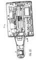
- Figure 13 is an interior view of a stringing platform.
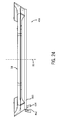
- Figure 14 is a cross-sectional view of the stringing platform of Figure 12 , taken along line 14-14.
- Figure 15 is a cross-sectional view of a releasable resistance assembly.
- Figure 16 is a front perspective view of a first releasable resistance assembly in accordance with an alternative preferred embodiment of the present invention.
- Figure 17 is a longitudinal cross-sectional view of the first releasable resistance assembly of FIG. 16 .
- Figures 18A and 18B are enlarged sectional views of a portion of the first releasable resistance assembly from circle 18 of FIG. 17 .
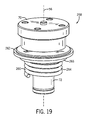
- Figure 19 is a front perspective view of a first releasable resistance assembly in accordance with another alternative preferred embodiment of the present invention.
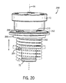
- Figure 20 is front view of the first releasable resistance assembly of FIG. 19 showing the movement of a first member about the first axis.
- Figure 21 is a front, upper perspective view of a first releasable resistance assembly in accordance with another alternative preferred embodiment of the present invention.
- Figure 22 is a front view of a first releasable resistance assembly of FIG. 21 illustrating the positioning of a caliper with respect to a disc.
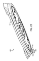
- Figure 23 is a front, lower perspective view of a first releasable resistance assembly in accordance with another alternative preferred embodiment of the present invention.
- Figure 24 is a front view of the first releasable resistance assembly of FIG. 23 .
- an ergonomically-designed racquet stringing machine is indicated generally at 20.
- the ergonomic features of the stringing machine 20 are intended to provide enhanced comfort for a user during the process of stringing a racquet.
- the stringing machine 20 includes a base 22 configured for supporting the stringing machine 20 on a generally horizontal surface, and a stand 24 having an upper end region 28 and a lower end region 30.
- the lower end region 30 of the stand 24 extends upwardly from a first location 32 on the base 22, and an adjustable stringing platform 26 is coupled to the upper end region 28 of the stand 24 at a second location 34 on the stringing platform 26, as shown in FIG. 3 .
- the "first location" 32 on the base 22 may be defined as the center of the footprint 36 resulting from the attachment of the stand 24 to the base 22.
- the “second location” 34 may be defined as the center of the footprint 38 resulting from the attachment of the stringing platform 26 to the stand 24.
- the "footprint” is a two-dimensional representation of the intersection of two parts that depicts the area of that intersection.
- the first and second locations 32, 34 define a line 40 that is angled by a predetermined angle ( ⁇ ) from horizontal. It is this line 40 to which we refer when discussing the angle ⁇ between the stand 24 and the base 22.
- the stand 24 itself may be curved, such as a "C" shape, or may appear to be bent at one or more locations along its length, but in any case, if the line 40 connecting the first location 32 and the second location 34 defines an angle ⁇ from horizontal within the range defmed herein, the stringing machine 20 is still considered to fall within the scope of this invention.
- the stand 24 extends from the base 22 at an angle ⁇ between about 70 and about 89 degrees from a horizontal plane (1 and 20 degrees from a vertical plane), in a direction generally toward the user.
- the angle ⁇ between the stand 24 and the base 22 may be between about 80 and about 85 degrees from a horizontal plane (5 and 10 degrees from a vertical plane), for example 83 degrees from a horizontal plane (7 degrees from a vertical plane).
- conventional stringing machines are configured with a stand that extends perpendicularly from a base. The angled orientation of the stand 24 described in the present invention provides ample legroom for the user standing in front of the stringing machine 20.
- a 7-degree tilt such that the angle ⁇ is 83 degrees from a horizontal plane, provides 40-50 % more legroom compared to a stand 24 that is perpendicular to the base 22.
- the base 22 may be configured to provide a comfortable standing area for the user.
- the base 22 includes a forward side 42 intended to face the user and a rear side 44 opposite the forward side 42. As illustrated in FIGS. 1-3 , the forward side 42 of the base 22 may define a recessed area for accommodating at least a portion of the user's feet, thereby enabling the user to stand closer to the racquet during the stringing process.
- the racquet When stringing a racquet, the racquet must first be clamped onto the adjustable stringing platform 26. As illustrated in FIG. 4 , conventional stringing machines 46 induce poor posture for many users trying to clamp the racquet onto the stringing platform.
- the stand 24 By configuring the stand 24 to extend at a non-perpendicular angle ⁇ between the base 22 and the stand 24 and increasing the height of the stand 24, the user in the desired operating position can stand closer to the stringing platform 26, thereby preventing the user from hunching over the stringing platform 26, as shown in FIG. 5 .
- the height of the stand 24 may either be fixed or adjustable. Any suitable height-adjusting mechanism can be applied to the stringing machine 20, such as a telescoping height-adjustment mechanism.
- the process of stringing the main strings may cause neck strain or other discomfort due to the positioning of the stringing platform with respect to the user's position.
- the positioning of the stringing platform 26 suitably provides a comfortable working area for the user in which the user, in the desired operating position, is able to stand upright in a relatively comfortable position, as shown in FIG. 7 .
- the detail-oriented process of weaving cross strings may also cause neck strain or other discomfort, as exemplified in FIG. 8 .
- the stand 24 By configuring the stand 24 to extend at a non-perpendicular angle ⁇ between the base 22 and the stand 24, the height and angle of the stringing platform 26 can be arranged in a position that allows the user to weave the cross strings in a more ergonomically preferable operating position, as shown in FIG. 9 .
- the base 22 and stand 24 may be a single-leg design, as illustrated in FIGS. 1 and 2 . Alternatively, a two-leg design, as illustrated in FIG. 10 , may work equally well. In any case, the base 22 may be die-cast for added stability.
- the major components of the stringing machine 20, namely the base 22, stand 24, and stringing platform 26, may be formed of metal, wood, plastic, high-strength polymers, composite materials, or any combination of these materials, for example.
- the angle ⁇ between the base 22 and the stand 24 may be permanently fixed, or non-adjustable. In other embodiments, however, the angle ⁇ between the base 22 and the stand 24 may be adjustable.
- a stand adjustment assembly capable of adjusting the angle ⁇ of the line 40 defined by the first and second locations 32, 34 may be coupled to the base 22 and the stand 24. The stand adjustment assembly may be configured to adjust the angle ⁇ of the line 40 within a range of 0.1 to 15.0 degrees.
- the angular adjustment between the base 22 and the stand 24 may be performed either manually or automatically.
- the stand adjustment assembly may include a drive mechanism formed by a chain that runs in a track.
- the drive mechanism may be controlled electronically, for example.
- Those skilled in the art are familiar with a variety of suitable drive mechanisms that would be appropriate for adjusting the angle ⁇ between the base 22 and the stand 24. Therefore, the details of such mechanisms will not be described in detail herein.
- the stringing platform 26 includes multiple frame clamps 48 for maintaining the frame of a racquet in place on the stringing platform 26, and two string clamps 50 for maintaining the strings in place during the stringing process.
- the stringing platform 26 and the frame clamps 48 support the racquet about a stringing plane.
- the stringing platform 26 can support the racquet such that the stringing plane of the racquet is angled with respect to a generally horizontal support surface.
- a string tensioning assembly 52 is coupled to the stand 24 atop the stringing platform 26. The string tensioning assembly 52 pulls the strings to the desired tension during the stringing process.
- the stringing platform 26 may either be configured as shown in FIGS. 11 and 12 or, alternatively, may be a conventional stringing platform as found on conventional stringing machines.
- the stringing platform 26 may include a turntable 54 rotatable about a first axis 56, and a first releasable resistance assembly 58, such as a grease brake, coupled to the turntable 54, as shown in FIGS. 11-13 .
- the turntable 54 allows the racquet to spin in a plane in which the frame of the racquet lies.
- the first releasable resistance assembly 58 may be positionable between an engaged operating position in which the resistance assembly 58 resists rotation of the turntable 54 about the first axis 56, and a disengaged operating position in which the resistance assembly 58 does not resist rotation of the turntable 54 about the first axis 56.
- the first releasable resistance assembly 58 can provide resistance to unintentional rotation of the turntable 54.
- the first releasable resistance assembly 58 can negate the effects of gravity when a racquet is in place and the stringing platform 26 is tilted, such as may be caused by the tilted angle of the stand 24.
- the first releasable resistance assembly may provide a resistance against rotation of the turntable (resistance against a torque) about the first axis of within the range of 0.1 to 36 in-lbf, or more preferably within the range of 0.1 to 12.0 in-lbf.
- the first releasable resistance assembly 58 suitably includes a high viscosity fluid, such as a grease, for resisting rotation of the turntable 54 when in the engaged operating position.
- the high viscosity fluid may have a viscosity range of 1 to 500 cP, for example.
- the first releasable resistance assembly 58 includes first and second members 60, 62 contacting the high viscosity fluid, with at least one of the first and second members 60, 62 being rotatable about the first axis 56.
- FIG. 14 is a cross-sectional view of the stringing platform 26, which illustrates the first and second members 60, 62 in the first releasable resistance assembly 58.
- a cross-sectional view of the first releasable resistance assembly 58 is shown in greater detail in FIG. 15 .
- the first and/or second members 60, 62 may include a plurality of projections, such as spaced-apart concentric rings, contacting the fluid.
- each of the first and second members 60, 62 may include a plurality of spaced-apart concentric rings with the rings of the first and second members 60, 62 configured to correspond to each other such that portions of the rings of one of the members fit within the spaces between the rings of the other member.
- the first and second members 60 and 62 can take be formed in other corresponding shapes having different numbers of projections in different orientations.
- the first releasable resistance assembly 58 may also include a latch 64 that releasably engages the first member 60 to prevent the first member 60 from rotating about the first axis 56.
- the latch 64 may be manually operated or remotely operated through a conventional actuation mechanism. In one preferred embodiment, the latch 64 can be used to switch the first resistance assembly 58 between the engaged operating position in which the resistance assembly 58 resists rotation of the turntable 54 about the first axis 56, and a disengaged operating position in which the resistance assembly 58 does not resist rotation of the turntable 54 about the first axis 56.
- the latch 64 When the latch 64 is positioned to engage the first member 60 and to prevent the member 60 from rotating about the first axis 56, the second member 62 remains free to rotate about the first axis 56.
- the second member 62 rotates with respect to the first member 60 and the high viscosity fluid positioned between the corresponding projections of the first and second members 60 and 62 provides resistance to rotation of the second member 62 about the first axis 56.
- a second releasable resistance assembly 66 may also be coupled to the stringing platform 26.
- the turntable 54 may include a ring 68 centered about the first axis 56, and the second releasable resistance assembly 66 may be configured to releasably engage the ring 68 to prevent rotation of the turntable 54 about the first axis 56.
- the mechanism of the second releasable resistance assembly 66 may be similar to a bicycle brake, with a lever operated by the user at one end and the opposite end designed to contact the inner surface of the ring 68 when the brake is applied, thus creating sufficient friction to prevent the turntable 54 from rotating.
- the second releasable resistance assembly 66 releasably locks into position by the user.
- the second releasable resistance assembly 66 is configured to directly stop the turntable 54 from rotating about the first axis 56, including bringing the turntable 54 to a stop in mid-rotation.
- first releasable resistance assembly 158 provides similar functional benefits of the first releasable resistance assembly 58.
- the first releasable resistance assembly 158 is coupled to the turntable 54 and to the stringing platform 26.
- the first releasable resistance assembly 158 is configured to be positionable between an engaged operating position in which the first resistance assembly 158 resists or inhibits rotation of the turntable 54 about the first axis 56, and a disengaged operating position in which the resistance assembly 158 does not resist rotation of the turntable 54 about the first axis 56.
- the first releasable resistance assembly 158 can provide resistance to unintentional rotation of the turntable 54, and in particular, it can negate the effects of gravity when a racquet is in place on the stringing machine 10 and the stringing platform 26 is tilted.
- the engaged operating position of the first releasable resistance assembly 158 can also be configured to vary the level of resistance that can be used to resist rotation of the turntable 54.
- the first releasable resistance assembly 158 is coupled to the turntable 54 ( FIG. 11 ) and the stringing platform 26 ( FIG. 11 ) through a turntable mount 70 having a central column 72 extending about the first axis 56.
- the first releasable resistance assembly 158 includes first and second members 160 and 162.
- the first member 160 surrounds the central column 72 and is positioned adjacent to the second member 162.
- the first member 160 is preferably fixed to the stringing platform 26 and does not rotate about the first axis 56.
- an actuation mechanism can be used to selectably lock or unlock the first member thereby either fixing the movement of the first member or enabling the first member to rotate about the first axis 56 and with the central column 72.
- the second member 162 is preferably configured to rotate about the first axis 56.
- the second member 162 can define a recess 168 for receiving a drive pin 170.
- the drive pin 170 is positioned within the recess 168 and causes the second member 162 to rotate about the first axis 56 and along with the central column 72.
- the other mechanisms for fixing and unfixing the rotational movement of one or both of the first and second members 162 and 162 about the first axis 56 can be employed.
- the actuation pin can be replaced with some other repositionable assembly, part or parts.
- the first and second members 160 and 162 define an annular cavity 164 for holding a magnetorheological fluid 166 ("MR fluid").
- the MR fluid 166 includes a percent by volume of small metallic particles 172 within a carrier fluid 174.
- the metallic particles 168 are preferably iron particles. In alternative preferred embodiments, other metallic particles can be used.
- the metallic particles 172 preferably take up approximately 20-40 percent by volume of the MR fluid 166. In other preferred embodiments other percent amounts by volume of particles within the MR fluid can be used.
- the particles 172 can be spherical, ellipsoids, other shapes and combinations thereof.
- the particles 172 are very small and can be in micrometer scale or in the nanometer scale.
- the particles have a size (or diameter) within the range of 3 to 10 microns. In another alternative preferred embodiment, the particles 168 can have a size within the range of 0.1 to 10 ⁇ m. In other preferred embodiment, other sizes and size ranges of particles can be used.
- the carrier fluid 174 is preferably an oil, such as a mineral oil or a synthetic oil. In alternative preferred embodiments, the carrier fluid can be other oils, water, glycol, other fluids or combinations thereof. Additives can also be added to the MR fluid 166 to discourage gravitational settling of the particles 172 and to promote particle suspension within the MR fluid 166.
- the MR fluid 166 is a free-flowing liquid generally having a consistency of oil. However, when the MR fluid 166 is subjected to a magnetic field 176, the MR fluid 166 greatly increases its apparent viscosity. The rheology of the fluid changes, virtually instantly, to a fluid with a much greater apparent viscosity. For example, the apparent viscosity of the MR fluid 166 under the magenetic field 176 can change such that the MR fluid 166 has a consistency of peanut butter.
- the magnetic field 176 is induced by applying a charge to the central column 72, by applying a current around the central column 72 or through other electrical means.
- the particles 172 in the MR fluid 166 are generally evenly or randomly dispersed within the fluid, and the fluid flows freely.
- the free flowing MR fluid 166 allows for free movement of relative parts, such as free movement of the first element 160 relative to the second member 162 when the first member 160 is in a fixed position.
- the particles 172 Upon the application of the magnetic field 176 (see FIG. 18B ), the particles 172 generally align along the flux path generated by the magnetic field 172.
- the formation of essentially chains of the particles 172 restricts the movement of the fluid within the cavity 164, and the fluid's yield strength and apparent viscosity is greatly increased.
- the inter-particle attraction or alignment of the particles 172 can be altered by increasing or decreasing the strength of the magnetic field 176 to control the rheological properties of the MR fluid 166, and hence the braking or resistance force of the MR fluid 166. Therefore, the MR fluid changing to a consistency of peanut butter is on example of the varying and available fluid consistencies. In one extreme, the consistency of the fluid can be comparable to a solid.
- One supplier of MR fluids for use with the present invention is Lord Corporation located at 111 Lord Drive, Cary, North Carolina 27511.
- the cavity 164 is defined to provide a volume for the MR fluid 166.
- the distance by which the MR fluid 166 separates the first and second members 160 and 162 can affect the change in viscosity of the MR fluid 166.
- the distance by which the MR fluid 166 separates the first and second members 160 and 162 is within the range of 0.25 to 5 mm. In another preferred embodiment, the distance is within the range of 0.5 to 2 mm. In other alternative preferred embodiments, other distances or ranges of distances can also be used.
- the first releasable resistance assembly can be configured such that the distance separating the first and second members can be selectably changed to alter the resistance against rotation of the turntable about the first axis that is applied by the MR fluid when the magnetic field is applied.
- the magnetic field 176 can be applied across the first and second members 160 and 162. Under the magnetic field 176, the apparent viscosity of the RH fluid 166 will significantly increase resisting and inhibiting rotation of the turntable 54 about the first axis 56.
- the application of the magnetic field 176 can be a simple on/off selection made at the stringing platform 26.
- the stringing platform 26 can be configured with a controller for varying the strength of the magnetic field 176 and therefore the apparent viscosity of the MR fluid to obtain a resistance level desired by the user.
- first releasable resistance assembly 258 provides similar functional benefits of the first releasable resistance assembly 58.
- the first releasable resistance assembly 258 is coupled to the turntable 54.
- the first releasable resistance assembly 258 is configured to be positionable between an engaged operating position in which the first resistance assembly 258 resists or inhibits rotation of the turntable 54 about the first axis 56, and a disengaged operating position in which the resistance assembly 258 does not resist rotation of the turntable 54 about the first axis 56.
- the first releasable resistance assembly 258 can provide resistance to unintentional rotation of the turntable 54, and in particular, it can negate the effects of gravity when a racquet is in place on the stringing machine 10 and the stringing platform 26 is tilted.
- the first releasable resistance assembly 258 is coupled to the turntable 54 ( FIG. 11 ) and the stringing platform 26 ( FIG. 11 ) through a turntable mount 70 having a central column 72 extending about the first axis 56.
- the first releasable resistance assembly 258 includes first and second members 260 and 262.
- the first member 260 surrounds the central column 72 and preferably includes a biasing member 264 and an engaging element 266.
- the biasing member 264 is preferably a coil spring, but can also be configured as other forms of springs or biasing devices.
- One portion of the biasing member 264 is preferably coupled to the stringing platform 26 to fix a first portion of the biasing member 264 and prevent the first portion from rotating about the first axis 56, and an upward portion of the biasing member 264 is coupled to the engaging element 266.
- the engaging element 266 is a disc like member configured for releasably and selectably engaging the second member 262.
- the second member 262 is preferably configured to rotate about the first axis 56.
- the second member 262, like the second member 162, can define a recess 268 for receiving a drive pin 270.
- the drive pin 270 is positioned within the recess 168 and causes the second member 262 to rotate about the first axis 56 and along with the central column 72.
- the first member 260 is preferably configured to be positionable and between a first operating position wherein the first member 260 operably engages the second member 262 to resist rotation of the second member 262 about the first axis 56, and a second operating position, wherein the first member 260 is decoupled from the second member 262 such that the second member 262 is free to rotate about the first axis 56 with the turntable 54 and the central column 72.
- the first member 260 can be moved along the first axis 56 to selectably engage or disengage the second member 262.
- the first releasable resistance assembly 258 is configured to resist or inhibit undesired rotation of a racquet placed onto the turntable and the stringing platform about the first axis 56 due to gravitational forces when the stringing platform is tilted with respect to a horizontal support surface.
- the user can selectably engage and disengage the first releasable resistance assembly 258 while stringing thereby engaging the first and second members 260 and 262 when the user wants the racquet to remain relatively still and in position, and disengage the first and second members 260 and 262 when the user desires to freely reposition and rotate the racquet about the first axis 56.
- first releasable resistance assembly 358 provides similar functional benefits of the first releasable resistance assembly 58.
- the first releasable resistance assembly 358 is coupled to the turntable 54 and to the stringing platform 26.
- the first releasable resistance assembly 358 is configured to be positionable between an engaged operating position in which the first resistance assembly 358 resists or inhibits rotation of the turntable 54 ( FIG. 11 ) about the first axis 56, and a disengaged operating position in which the resistance assembly 358 does not resist rotation of the turntable 54 about the first axis 56.
- the first releasable resistance assembly 358 can provide resistance to unintentional rotation of the turntable 54, and in particular, it can negate the effects of gravity when a racquet is in place on the stringing machine 10 and the stringing platform 26 is tilted.
- the first releasable resistance assembly 358 is coupled to the turntable 54 ( FIG. 11 ) and the stringing platform 26 ( FIG. 11 ) through a turntable mount 70 having a central column 72 extending about the first axis 56.
- the first releasable resistance assembly 358 includes a first disc 360 and a movable caliper 362.
- the first disc 360 is a generally planar, circular plate having a plurality of recesses 364 for receiving a plurality of metallic elements 366.
- the first disc 360 is fixed to the central column 72 and rotates with the central column 72 about the first axis 56.
- a pin 368 is used to connect the central column 72 to the disc 360.
- the caliper 362 includes a curved slot 370 for selectably receiving a portion of the disc 360.
- the caliper 362 selectably straddles a portion of the disc 360.
- the caliper 362 is formed at least in part of a metallic material.
- One or more of the caliper and the metallic elements 366 can be configured as magnets.
- the caliper 362 is operably coupled to the stringing platform 26.
- the magnetic field between the metallic elements 366 and the caliper 362 brakes, resists or inhibits the rotation of the disc 360 about the first axis 56.
- the amount of braking force or resistance applied to the disc 360 can be selected by varying the magnetic field formed by the metallic elements 366 and the caliper 362. This can be accomplished by varying the size of the metallic elements 366 and the metallic material of the caliper 362 or by varying the distance between the disc 360 and the caliper 362.
- the caliper 362 can be configured to be positionable between an engaged position and a disengaged position.
- the caliper 362 In the engaged position, the caliper 362 straddles a portion of the disc 360 such that the portion of the disc 360 extends into the curved slot 370 of the caliper 362. The caliper 362 extends over one or more of the metallic elements 366. In the engaged position, a magnetic field is formed that resists or inhibits the rotation of the disc 360 and therefore the central column 72 about the first axis 56. In the disengaged position, the caliper 362 is spaced apart from the disc 360 such that the caliper no longer extends over a portion of the disc 360. No magnetic braking force is applied to the disc when the caliper 362 is in the disengaged position thereby enabling the disc 360 to be freely rotated by the user.
- the disc 360 can include one or more projections outwardly extending from the central column 72.
- the disc may have a circular shape or other geometric shapes including irregular shapes.
- the metallic elements 366 can be circular magnets or magnets of other shapes.
- the metallic elements 366 can be formed of magnetized or non-magnetized metallic material. The user therefore can selectably engage and disengage the first releasable resistance assembly 358.
- the caliper 362 When engaged, the caliper 362 will straddle the disc 360 and the magnetic field formed by the caliper 362 and the metallic elements 366 will resist or inhibit rotation of the central column 72 about the first axis 56and when disengage, the caliper 362 will be positioned away from the disc 360 reducing or eliminating the magnetic field and enabling the disc 360 and the central column to be freely rotated about the first axis 56.
- first releasable resistance assembly 458 provides similar functional benefits of the first releasable resistance assembly 58.
- the first releasable resistance assembly 358 is coupled to the turntable 54 and to the stringing platform 26.
- the first releasable resistance assembly 358 is configured to be positionable between an engaged operating position in which the first resistance assembly 458 resists or inhibits rotation of the turntable 54 about the first axis 56, and a disengaged operating position in which the resistance assembly 458 does not resist rotation of the turntable 54 about the first axis 56.
- the first releasable resistance assembly 458 can provide resistance to unintentional rotation of the turntable 54, and in particular, it can negate the effects of gravity when a racquet is in place on the stringing machine 10 and the stringing platform 26 is tilted.
- the first releasable resistance assembly 458 is releasably connected to a ring 460 formed on the underside of the turntable 54.
- the first releaseable resistance assembly 458 includes a pair of brake pads 462 positioned onto a pair of brake arms 464.
- the brake arms 464 are coupled to the stringing platform 26 and are not configured to rotate about the first axis 56.
- the brake pads 462 are positioned on the underside of the turntable 54 adjacent to the inner and outer surfaces of the ring 460. As the turntable 54 rotates about the first axis 56, the ring 460 extends through the space existing between the brake pads 462.
- the brake arms 464 and the brake pads 462 are selectably positionable, such that when actuated the brake arms 464 and the brake pads 462 are drawn closer to each other such that the brake pads 462 contact the inner and/or outer surfaces of the ring 460 to apply a braking force or resistance inhibiting the rotation of the turntable 54 relative to the first axis 56.
- the user therefore can selectably engage and disengage the first releasable resistance assembly 458.
- the brake pads 462 When engaged, the brake pads 462 will draw together and contact the ring 460 of the turntable 54 and will resist or inhibit rotation of the turntable 54 about the first axis 56 and when disengage, the brake pads 462 will be spaced apart and away from the ring 460 enabling the disc 360 and the central column to be freely rotated about the first axis 56.
- the first releasable resistance assembly 458 can be configured as an on/off assembly or as an assembly that can produce a varied amount of resistance countering the rotation of the turntable 54 as desired by the user through the use of a controller coupled to the stringing platform.
- the first releasable resistance assemblies 58, 158, 258, 358 and 458 when in an engaged operating mode can each apply sufficient resistance to resist the rotation of the turntable about the first axis such that when a racquet is mounted to the stringing platform and the stringing platform and/or the stringing plane of the racquet is angled with respect to the generally horizontal support surface, gravity does not cause the racquet to rotate about the first axis.
- This feature is particularly useful when the handle of the racquet is positioned at a height that is equal to or greater than the height of the string bed of the racquet.
- the first releasable resistance assembly 58, 158, 258, 358 or 458 prevents rotation of the racquet about the first axis due to the force of gravity or gravitational forces acting on the racquet.
- the resistance level applied to resist the rotation of the turntable about the first axis can be selected such that it does not prevent the user of the stringing machine 20 from manually contacting and moving the racquet about the first axis 56.
- Each embodiment of the first releasable resistance assembly 156, 256, 356 and 456 is configured to resist a torque about the first axis within the range of 0.1 to 36 in-lbf. In one set of preferred embodiments, each embodiment of the first releasable resistance assembly 156, 256, 356 and 456 is configured to resist a torque about the first axis within the range of 0.1 to 12 in-lbf. In other preferred embodiments, the resistance force applied by the first releasable resistance assembly 156, 256, 356 and 456 is 3 lbs or less.
- any one or more of the stringing machine embodiments described herein may be applied to machines for stringing tennis racquets, racquetball racquets, squash racquets, badminton racquets, and any other strung racquet.
- the stringing machine 20 may be used to string racquets for use in an organized professional league and/or in competitive play.
- the stringing machine 20 may be configured to string racquets in a manner that meets ITF Rules of Tennis requirements for racquet strings. Regardless of the type of racquet, compatibility of the stringing machine 20 with the user is greatly improved by using any of the stringing machine enhancements in this invention.
Landscapes
- Health & Medical Sciences (AREA)
- General Health & Medical Sciences (AREA)
- Physical Education & Sports Medicine (AREA)
- Braking Arrangements (AREA)
- Pivots And Pivotal Connections (AREA)
Abstract
A stringing machine includes a base and an adjustable stringing platform coupled to the base. The stringing platform includes a turntable rotatable about a first axis, and a first releasable resistance assembly coupled to the turntable. The first releasable resistance assembly is selectable between an engaged operating mode in which the releasable resistance assembly resists rotation of the turntable about the first axis, and a disengaged operating mode in which the releasable resistance assembly does not resist rotation of the turntable about the first axis. The releasable resistance assembly can include a magnetorheological fluid for resisting rotation of the turntable about the first axis when in the engaged operating mode.
Description
- The present invention relates to a machine for stringing racquets. This stringing machine has enhanced ergonomic features.
- The act of stringing a racquet requires a considerable amount of manual labor. Stringing machines assist in the process by maintaining the racquet in place and providing desired tension in the strings, but a majority of the work involved is performed by a person. More particularly, a person must align the racquet within the stringing machine, and then string each of the cross or main strings individually, followed by weaving each of the cross and main strings to form the resulting string grid.
- Those in the racquet stringing business often spend many hours a day standing in front of a stringing machine. Conventional stringing machines include a stringing platform with a turntable positioned on top of a fixed stand. The turntable spins within a plane parallel to the floor. Because of the fixed orientation of the stand and the planar position of the turntable, the person stringing the racquet must adjust his or her posture to conform to the position of the stringing machine. In particular, one of the racquet stringer's shoulders is often positioned much higher than the other. Also, the fixed orientation of the stringing machine often induces the racquet stringer to hunch over the turntable. The awkward posture induced by conventional stringing machines often causes injuries and fatigue, which ultimately lead to reduced efficiency in the performance of the racquet stringer. Additionally, conventional stringing machines typically include a vertical stand on a base. The stand and/or base can interfere with the placement of the stringer's feet and/or legs, leading to additional awkwardness in the stringer's posture.
- During the stringing process, the racquet is clamped to the stringing platform and the turntable allows the racquet stringer to manually spin the racquet to adjust the positioning of the racquet with respect to the various steps of the stringing process. Turntables on conventional stringing machines are generally free to spin in response to any applied tangential force unless or until a brake is applied, with the brake preventing any further spinning. If the stringing platform were positioned in the stringing machine such that the turntable spins in a plane non-parallel with the floor, namely tilted toward the racquet stringer, the handle of any racquet clamped to the stringing platform would be drawn by gravity to the lowest point within the plane. Consequently, even though the positioning of the angled or tilted turntable may be more comfortable for the user, the need to either continually move the racquet back into its intended position or continually lock and unlock the brake on the turntable in order to overcome the effects of gravity on the clamped-on racquet would be a nuisance.
- It would thus be desirable to provide a stringing machine that is ergonomically designed to allow users to work with the stringing machine without having to assume awkward or uncomfortable positions, and without having to continuously manually override effects of gravity on the turntable.
- The present invention presents an ergonomically-designed racquet stringing machine for stringing of a racquet by a user. The stringing machine includes a base configured for supporting the stringing machine on a generally horizontal surface, a stand having upper and lower end regions, the lower end region of the stand upwardly extending from a first location of the base, an adjustable stringing platform coupled at a second location to the upper end region of the stand, and a string tensioning assembly coupled to the stand.
- The "first location" of the base may be defined as the center of the footprint resulting from the attachment of the stand to the base. Similarly, the "second location" may be defmed as the center of the footprint resulting from the attachment of the stringing platform to the stand. The "footprint" is a two-dimensional representation of the intersection of two parts that depicts the area of that intersection. The first and second locations define a line that is angled by a predetermined angle from horizontal.
- In one embodiment, the stand extends from the base at an angle between about 70 and about 89 degrees from a horizontal plane (1 and 20 degrees from a vertical plane). Alternatively, the angle between the stand and the base may be between about 80 and about 85 degrees from a horizontal plane (5 and 10 degrees from a vertical plane), for example 83 degrees from a horizontal plane (7 degrees from a vertical plane). This angled orientation of the stand provides ample legroom for the user standing in front of the stringing machine. Additionally, a forward side of the base intended to face the user may defme a recessed area for accommodating at least a portion of the user's feet thereby enabling the user to stand closer to the racquet during stringing.
- The angle between the base and the stand may be adjustable. For instance, a stand adjustment assembly capable of adjusting the angle of the line defined by the first and second locations may be coupled to the base and the stand. The stand adjustment assembly may be configured to adjust the angle of the line within a range of 0.1 to 15.0 degrees.
- In another embodiment, the adjustable stringing platform may include a turntable rotatable about a first axis, and a first releasable resistance assembly, such as a grease brake, coupled to the turntable. The first releasable resistance assembly may be positionable between an engaged operating position in which the resistance assembly resists rotation of the turntable about the first axis, and a disengaged operating position in which the resistance assembly does not resist rotation of the turntable about the first axis.
- The first releasable resistance assembly can provide resistance to unintentional rotation of the turntable. In particular, the first releasable resistance assembly can negate the effects of gravity when a racquet is in place and the stringing platform is tilted, such as may be caused by the tilted angle of the stand. For example, the first releasable resistance assembly may provide a resistance against rotation of the turntable (resistance against a torque) about the first axis of within the range of 0.1 to 36 in-lbf, or more preferably within the range of 0.1 to 12.0 in-lbf.
- The first releasable resistance assembly suitably includes a high viscosity fluid, such as a grease, for resisting rotation of the turntable when in the engaged operating position. The high viscosity fluid may have a viscosity range of 1 to 500 centipoise (cP), for example. In certain embodiments, the first releasable resistance assembly includes first and second members contacting the high viscosity fluid, with at least one of the first and second members being rotatable about the first axis. The first and/or second members may include a plurality of projections, such as spaced-apart concentric rings, contacting the fluid. For example, each of the first and second members may include a plurality of spaced-apart concentric rings with the rings of the first and second portions configured to correspond to each other such that portions of the rings of one of the members fit within the spaces between the rings of the other member. The first releasable resistance assembly may also include a latch that releasably engages the first member to prevent the first member from rotating about the first axis.
- A second releasable resistance assembly, separate from the first releasable resistance assembly, may also be coupled to the stringing platform. For example, the turntable may include a ring centered about the first axis, and the second releasable resistance assembly may be configured to releasably engage the ring to prevent rotation of the turntable about the first axis.
- The present invention provides a stringing machine includes a base and an adjustable stringing platform coupled to the base. The stringing platform includes a turntable rotatable about a first axis, and a first releasable resistance assembly coupled to the turntable. The first releasable resistance assembly is selectable between an engaged operating mode in which the releasable resistance assembly resists rotation of the turntable about the first axis, and a disengaged operating mode in which the releasable resistance assembly does not resist rotation of the turntable about the first axis. The releasable resistance assembly includes a magnetorheological fluid for resisting rotation of the turntable about the first axis when in the engaged operating mode (cf. also claim 1).
- Advantageous embodiments of such stringing machine are defined by claims 2 to 5.
- According to a particular embodiment of such stringing machine, the magnetorheological fluid includes a carrier fluid and a quantity of magnetic particles within the carrier fluid, wherein the size of the particles falls within one of a micrometer scale and a nanometer scale. For example, the carrier fluid can be selected from the group consisting of a mineral oil, a synthetic oil, water, glycol, other oils, other fluids and combinations thereof.
- According to an embodiment, a magnetic field is induced across the first releasable resistance assembly. For example, the magnetic field can be induced across the first releasable resistance assembly when the first releasable resistance assembly is in the engaged operating mode, and the magnetic field can be removed from the first releasable resistance assembly when the first releasable resistance assembly is in the disengaged operating mode. In a development of this embodiment, the magnetic field is varied to vary the resistance that is applied by the first releasable resistance assembly to resist rotation of the turntable about the first axis.
- According to a principal aspect of a preferred form of the invention, a stringing machine is configured to support a racquet. The stringing machine includes a base and an adjustable stringing platform coupled to the base. The stringing platform includes a turntable rotatable about a first axis, and a first releasable resistance assembly coupled to the turntable. The turntable includes a ring centered about the first axis. The first releasable resistance assembly is selectable between an engaged operating mode in which the releasable resistance assembly applies a resistance force of 3 lbs or less against the rotation of the turntable about the first axis, and a disengaged operating mode in which the releasable resistance assembly does not resist rotation of the turntable about the first axis. The first releasable resistance assembly includes a pair of brake arms configured to selectably engage the ring for resisting rotation of the turntable about the first axis when in the engaged operating mode (cf. also claim 6).
- Advantageous embodiments of such stringing machine are defined by claims 7 to 10.
- According to another principal aspect of a preferred form of the invention, a stringing machine is configured to support a racquet. The stringing machine includes a base and a stringing platform coupled to the base. The stringing platform includes a a turntable rotatable about a first axis, a first releasable resistance assembly coupled to the turntable, and a second releasable resistance assembly coupled to the stringing platform and the turntable. The first releasable resistance assembly is selectable between an engaged operating mode in which the releasable resistance assembly applies a resistance force of 3 lbs or less against the rotation of the turntable about the first axis, and a disengaged operating mode in which the releasable resistance assembly does not resist rotation of the turntable about the first axis. The second releasable resistance assembly when activated locks the turntable preventing the turntable from rotating about the first axis (cf. also claim 11).
- Advantageous embodiments of such stringing machine are defined by claims 12 to 15.
- Any one or more of the stringing machine embodiments described herein may be applied to machines for stringing tennis racquets, racquetball racquets, squash racquets, badminton racquets, and any other strung racquet. Regardless of the type of racquet, compatibility of the stringing machine with the user is greatly improved by using any of the stringing machine enhancements in this invention.
- This invention will become more fully understood from the following detailed description, taken in conjunction with the accompanying drawings described herein below, and wherein like reference numerals refer to like parts.
-
Figure 1 is a perspective view of a racquet stringing machine. -
Figure 2 is a side view of a racquet stringing machine. -
Figure 3 is a schematic view of a racquet stringing machine. -
Figure 4 is a side view of a user in an induced posture while clamping a racquet on a racquet stringing machine. -
Figure 5 is a side view of a user in a preferred posture while clamping a racquet on a racquet stringing machine. -
Figure 6 is a side view of a user in an induced posture while stringing main strings on a racquet. -
Figure 7 is a side view of a user in a preferred posture while stringing main strings on a racquet. -
Figure 8 is a side view of a user in an induced posture while weaving cross strings on a racquet. -
Figure 9 is a side view of a user in a preferred posture while weaving cross strings on a racquet. -
Figure 10 is another perspective view of a racquet stringing machine. -
Figure 11 is a top view of a stringing platform on a racquet stringing machine. -
Figure 12 is a perspective view of a stringing platform. -
Figure 13 is an interior view of a stringing platform. -
Figure 14 is a cross-sectional view of the stringing platform ofFigure 12 , taken along line 14-14. -
Figure 15 is a cross-sectional view of a releasable resistance assembly. -
Figure 16 is a front perspective view of a first releasable resistance assembly in accordance with an alternative preferred embodiment of the present invention. -
Figure 17 is a longitudinal cross-sectional view of the first releasable resistance assembly ofFIG. 16 . -
Figures 18A and 18B are enlarged sectional views of a portion of the first releasable resistance assembly fromcircle 18 ofFIG. 17 . -
Figure 19 is a front perspective view of a first releasable resistance assembly in accordance with another alternative preferred embodiment of the present invention. -
Figure 20 is front view of the first releasable resistance assembly ofFIG. 19 showing the movement of a first member about the first axis. -
Figure 21 is a front, upper perspective view of a first releasable resistance assembly in accordance with another alternative preferred embodiment of the present invention. -
Figure 22 is a front view of a first releasable resistance assembly ofFIG. 21 illustrating the positioning of a caliper with respect to a disc. -
Figure 23 is a front, lower perspective view of a first releasable resistance assembly in accordance with another alternative preferred embodiment of the present invention. -
Figure 24 is a front view of the first releasable resistance assembly ofFIG. 23 . - Referring to
FIGS. 1 and2 , an ergonomically-designed racquet stringing machine is indicated generally at 20. The ergonomic features of the stringingmachine 20 are intended to provide enhanced comfort for a user during the process of stringing a racquet. - The stringing
machine 20 includes a base 22 configured for supporting the stringingmachine 20 on a generally horizontal surface, and astand 24 having anupper end region 28 and alower end region 30. Thelower end region 30 of thestand 24 extends upwardly from afirst location 32 on thebase 22, and anadjustable stringing platform 26 is coupled to theupper end region 28 of thestand 24 at asecond location 34 on thestringing platform 26, as shown inFIG. 3 . - The "first location" 32 on the
base 22 may be defined as the center of thefootprint 36 resulting from the attachment of thestand 24 to thebase 22. Similarly, the "second location" 34 may be defined as the center of thefootprint 38 resulting from the attachment of thestringing platform 26 to thestand 24. The "footprint" is a two-dimensional representation of the intersection of two parts that depicts the area of that intersection. The first andsecond locations line 40 that is angled by a predetermined angle (θ) from horizontal. It is thisline 40 to which we refer when discussing the angle θ between thestand 24 and thebase 22. Thestand 24 itself may be curved, such as a "C" shape, or may appear to be bent at one or more locations along its length, but in any case, if theline 40 connecting thefirst location 32 and thesecond location 34 defines an angle θ from horizontal within the range defmed herein, the stringingmachine 20 is still considered to fall within the scope of this invention. - In certain embodiments, the
stand 24 extends from the base 22 at an angle θ between about 70 and about 89 degrees from a horizontal plane (1 and 20 degrees from a vertical plane), in a direction generally toward the user. Alternatively, the angle θ between thestand 24 and the base 22 may be between about 80 and about 85 degrees from a horizontal plane (5 and 10 degrees from a vertical plane), for example 83 degrees from a horizontal plane (7 degrees from a vertical plane). In contrast, conventional stringing machines are configured with a stand that extends perpendicularly from a base. The angled orientation of thestand 24 described in the present invention provides ample legroom for the user standing in front of the stringingmachine 20. More particularly, by tilting thestand 24 at an angle θ non-perpendicular to thebase 22, more legroom can be created for the user, thereby allowing the user to stand closer to the stringingmachine 20. For example, a 7-degree tilt, such that the angle θ is 83 degrees from a horizontal plane, provides 40-50 % more legroom compared to astand 24 that is perpendicular to thebase 22. - Additionally, the
base 22 may be configured to provide a comfortable standing area for the user. Thebase 22 includes aforward side 42 intended to face the user and arear side 44 opposite theforward side 42. As illustrated inFIGS. 1-3 , theforward side 42 of the base 22 may define a recessed area for accommodating at least a portion of the user's feet, thereby enabling the user to stand closer to the racquet during the stringing process. - When stringing a racquet, the racquet must first be clamped onto the
adjustable stringing platform 26. As illustrated inFIG. 4 ,conventional stringing machines 46 induce poor posture for many users trying to clamp the racquet onto the stringing platform. By configuring thestand 24 to extend at a non-perpendicular angle θ between the base 22 and thestand 24 and increasing the height of thestand 24, the user in the desired operating position can stand closer to thestringing platform 26, thereby preventing the user from hunching over the stringingplatform 26, as shown inFIG. 5 . The height of thestand 24 may either be fixed or adjustable. Any suitable height-adjusting mechanism can be applied to the stringingmachine 20, such as a telescoping height-adjustment mechanism. - Additional steps in the stringing process also induce poor posture for many users. As shown in
FIG. 6 , the process of stringing the main strings may cause neck strain or other discomfort due to the positioning of the stringing platform with respect to the user's position. Once again, by configuring thestand 24 to extend at a non-perpendicular angle θ between the base 22 and thestand 24 and increasing the height of thestand 24, the positioning of thestringing platform 26 suitably provides a comfortable working area for the user in which the user, in the desired operating position, is able to stand upright in a relatively comfortable position, as shown inFIG. 7 . - Similarly, the detail-oriented process of weaving cross strings may also cause neck strain or other discomfort, as exemplified in
FIG. 8 . By configuring thestand 24 to extend at a non-perpendicular angle θ between the base 22 and thestand 24, the height and angle of thestringing platform 26 can be arranged in a position that allows the user to weave the cross strings in a more ergonomically preferable operating position, as shown inFIG. 9 . - The
base 22 and stand 24 may be a single-leg design, as illustrated inFIGS. 1 and2 . Alternatively, a two-leg design, as illustrated inFIG. 10 , may work equally well. In any case, thebase 22 may be die-cast for added stability. The major components of the stringingmachine 20, namely thebase 22, stand 24, and stringingplatform 26, may be formed of metal, wood, plastic, high-strength polymers, composite materials, or any combination of these materials, for example. - In certain embodiments, the angle θ between the base 22 and the
stand 24 may be permanently fixed, or non-adjustable. In other embodiments, however, the angle θ between the base 22 and thestand 24 may be adjustable. For instance, a stand adjustment assembly capable of adjusting the angle θ of theline 40 defined by the first andsecond locations base 22 and thestand 24. The stand adjustment assembly may be configured to adjust the angle θ of theline 40 within a range of 0.1 to 15.0 degrees. - The angular adjustment between the base 22 and the
stand 24 may be performed either manually or automatically. For example, the stand adjustment assembly may include a drive mechanism formed by a chain that runs in a track. The drive mechanism may be controlled electronically, for example. Those skilled in the art are familiar with a variety of suitable drive mechanisms that would be appropriate for adjusting the angle θ between the base 22 and thestand 24. Therefore, the details of such mechanisms will not be described in detail herein. - As illustrated in
FIG. 11 , the stringingplatform 26 includes multiple frame clamps 48 for maintaining the frame of a racquet in place on thestringing platform 26, and two string clamps 50 for maintaining the strings in place during the stringing process. Referring toFIG. 2 , the stringingplatform 26 and the frame clamps 48 support the racquet about a stringing plane. Referring toFIGS. 7 and9 , the stringingplatform 26 can support the racquet such that the stringing plane of the racquet is angled with respect to a generally horizontal support surface. As shown inFIG. 12 , astring tensioning assembly 52 is coupled to thestand 24 atop the stringingplatform 26. Thestring tensioning assembly 52 pulls the strings to the desired tension during the stringing process. Thestringing platform 26 may either be configured as shown inFIGS. 11 and12 or, alternatively, may be a conventional stringing platform as found on conventional stringing machines. - In certain embodiments, the stringing
platform 26 may include aturntable 54 rotatable about afirst axis 56, and a firstreleasable resistance assembly 58, such as a grease brake, coupled to theturntable 54, as shown inFIGS. 11-13 . Theturntable 54 allows the racquet to spin in a plane in which the frame of the racquet lies. The firstreleasable resistance assembly 58 may be positionable between an engaged operating position in which theresistance assembly 58 resists rotation of theturntable 54 about thefirst axis 56, and a disengaged operating position in which theresistance assembly 58 does not resist rotation of theturntable 54 about thefirst axis 56. - The first
releasable resistance assembly 58 can provide resistance to unintentional rotation of theturntable 54. In particular, the firstreleasable resistance assembly 58 can negate the effects of gravity when a racquet is in place and thestringing platform 26 is tilted, such as may be caused by the tilted angle of thestand 24. For example, the first releasable resistance assembly may provide a resistance against rotation of the turntable (resistance against a torque) about the first axis of within the range of 0.1 to 36 in-lbf, or more preferably within the range of 0.1 to 12.0 in-lbf. - The first
releasable resistance assembly 58 suitably includes a high viscosity fluid, such as a grease, for resisting rotation of theturntable 54 when in the engaged operating position. The high viscosity fluid may have a viscosity range of 1 to 500 cP, for example. By using such a highly viscous lubricant, theturntable 54 can be maintained in place, even when theturntable 54 is lying in a plane non-parallel to the horizontal surface on which the stringingmachine 20 is standing, without the need to mechanically lock theturntable 54 in place. - In certain embodiments, the first
releasable resistance assembly 58 includes first andsecond members second members first axis 56.FIG. 14 is a cross-sectional view of thestringing platform 26, which illustrates the first andsecond members releasable resistance assembly 58. A cross-sectional view of the firstreleasable resistance assembly 58 is shown in greater detail inFIG. 15 . The first and/orsecond members second members second members second members - The first
releasable resistance assembly 58 may also include alatch 64 that releasably engages thefirst member 60 to prevent thefirst member 60 from rotating about thefirst axis 56. Thelatch 64 may be manually operated or remotely operated through a conventional actuation mechanism. In one preferred embodiment, thelatch 64 can be used to switch thefirst resistance assembly 58 between the engaged operating position in which theresistance assembly 58 resists rotation of theturntable 54 about thefirst axis 56, and a disengaged operating position in which theresistance assembly 58 does not resist rotation of theturntable 54 about thefirst axis 56. When thelatch 64 is positioned to engage thefirst member 60 and to prevent themember 60 from rotating about thefirst axis 56, thesecond member 62 remains free to rotate about thefirst axis 56. However, with thefirst member 60 in a locked position, thesecond member 62 rotates with respect to thefirst member 60 and the high viscosity fluid positioned between the corresponding projections of the first andsecond members second member 62 about thefirst axis 56. - As illustrated in
FIG. 13 , a secondreleasable resistance assembly 66, separate from the firstreleasable resistance assembly 58, may also be coupled to thestringing platform 26. For example, as shown inFIG. 11 , theturntable 54 may include aring 68 centered about thefirst axis 56, and the secondreleasable resistance assembly 66 may be configured to releasably engage thering 68 to prevent rotation of theturntable 54 about thefirst axis 56. The mechanism of the secondreleasable resistance assembly 66 may be similar to a bicycle brake, with a lever operated by the user at one end and the opposite end designed to contact the inner surface of thering 68 when the brake is applied, thus creating sufficient friction to prevent theturntable 54 from rotating. Preferably, the secondreleasable resistance assembly 66 releasably locks into position by the user. In contrast with the firstreleasable resistance assembly 58, which merely resists rotation, the secondreleasable resistance assembly 66 is configured to directly stop theturntable 54 from rotating about thefirst axis 56, including bringing theturntable 54 to a stop in mid-rotation. - Referring to
FIGS. 16-18A&B , an alternative preferred embodiment of a firstreleasable resistance assembly 158 is shown. The firstreleasable resistance assembly 158 provides similar functional benefits of the firstreleasable resistance assembly 58. The firstreleasable resistance assembly 158 is coupled to theturntable 54 and to thestringing platform 26. The firstreleasable resistance assembly 158 is configured to be positionable between an engaged operating position in which thefirst resistance assembly 158 resists or inhibits rotation of theturntable 54 about thefirst axis 56, and a disengaged operating position in which theresistance assembly 158 does not resist rotation of theturntable 54 about thefirst axis 56. The firstreleasable resistance assembly 158 can provide resistance to unintentional rotation of theturntable 54, and in particular, it can negate the effects of gravity when a racquet is in place on the stringing machine 10 and thestringing platform 26 is tilted. The engaged operating position of the firstreleasable resistance assembly 158 can also be configured to vary the level of resistance that can be used to resist rotation of theturntable 54. - The first
releasable resistance assembly 158 is coupled to the turntable 54 (FIG. 11 ) and the stringing platform 26 (FIG. 11 ) through aturntable mount 70 having acentral column 72 extending about thefirst axis 56. The firstreleasable resistance assembly 158 includes first andsecond members first member 160 surrounds thecentral column 72 and is positioned adjacent to thesecond member 162. Thefirst member 160 is preferably fixed to thestringing platform 26 and does not rotate about thefirst axis 56. In an alternative preferred embodiment, an actuation mechanism can be used to selectably lock or unlock the first member thereby either fixing the movement of the first member or enabling the first member to rotate about thefirst axis 56 and with thecentral column 72. Thesecond member 162 is preferably configured to rotate about thefirst axis 56. Thesecond member 162 can define arecess 168 for receiving adrive pin 170. Thedrive pin 170 is positioned within therecess 168 and causes thesecond member 162 to rotate about thefirst axis 56 and along with thecentral column 72. In alternative preferred embodiments, the other mechanisms for fixing and unfixing the rotational movement of one or both of the first andsecond members first axis 56 can be employed. The actuation pin can be replaced with some other repositionable assembly, part or parts. - The first and
second members annular cavity 164 for holding a magnetorheological fluid 166 ("MR fluid"). TheMR fluid 166 includes a percent by volume of smallmetallic particles 172 within acarrier fluid 174. Themetallic particles 168 are preferably iron particles. In alternative preferred embodiments, other metallic particles can be used. Themetallic particles 172 preferably take up approximately 20-40 percent by volume of theMR fluid 166. In other preferred embodiments other percent amounts by volume of particles within the MR fluid can be used. Theparticles 172 can be spherical, ellipsoids, other shapes and combinations thereof. Theparticles 172 are very small and can be in micrometer scale or in the nanometer scale. In one preferred embodiment, the particles have a size (or diameter) within the range of 3 to 10 microns. In another alternative preferred embodiment, theparticles 168 can have a size within the range of 0.1 to 10 µm. In other preferred embodiment, other sizes and size ranges of particles can be used. Thecarrier fluid 174 is preferably an oil, such as a mineral oil or a synthetic oil. In alternative preferred embodiments, the carrier fluid can be other oils, water, glycol, other fluids or combinations thereof. Additives can also be added to theMR fluid 166 to discourage gravitational settling of theparticles 172 and to promote particle suspension within theMR fluid 166. - The
MR fluid 166 is a free-flowing liquid generally having a consistency of oil. However, when theMR fluid 166 is subjected to amagnetic field 176, theMR fluid 166 greatly increases its apparent viscosity. The rheology of the fluid changes, virtually instantly, to a fluid with a much greater apparent viscosity. For example, the apparent viscosity of theMR fluid 166 under themagenetic field 176 can change such that theMR fluid 166 has a consistency of peanut butter. Themagnetic field 176 is induced by applying a charge to thecentral column 72, by applying a current around thecentral column 72 or through other electrical means. - In the absence of the magnetic field 176 (see
FIG. 18A ), theparticles 172 in theMR fluid 166 are generally evenly or randomly dispersed within the fluid, and the fluid flows freely. The free flowingMR fluid 166 allows for free movement of relative parts, such as free movement of thefirst element 160 relative to thesecond member 162 when thefirst member 160 is in a fixed position. Upon the application of the magnetic field 176 (seeFIG. 18B ), theparticles 172 generally align along the flux path generated by themagnetic field 172. The formation of essentially chains of theparticles 172 restricts the movement of the fluid within thecavity 164, and the fluid's yield strength and apparent viscosity is greatly increased. The inter-particle attraction or alignment of theparticles 172 can be altered by increasing or decreasing the strength of themagnetic field 176 to control the rheological properties of theMR fluid 166, and hence the braking or resistance force of theMR fluid 166. Therefore, the MR fluid changing to a consistency of peanut butter is on example of the varying and available fluid consistencies. In one extreme, the consistency of the fluid can be comparable to a solid. One supplier of MR fluids for use with the present invention is Lord Corporation located at 111 Lord Drive, Cary, North Carolina 27511. - In one preferred embodiment the
cavity 164 is defined to provide a volume for theMR fluid 166. The distance by which theMR fluid 166 separates the first andsecond members MR fluid 166. In one preferred embodiment, the distance by which theMR fluid 166 separates the first andsecond members - When the first
releasable resistance assembly 158 is in an engaged operating position, themagnetic field 176 can be applied across the first andsecond members magnetic field 176, the apparent viscosity of theRH fluid 166 will significantly increase resisting and inhibiting rotation of theturntable 54 about thefirst axis 56. In one preferred embodiment, the application of themagnetic field 176 can be a simple on/off selection made at thestringing platform 26. In another alternative preferred embodiment, the stringingplatform 26 can be configured with a controller for varying the strength of themagnetic field 176 and therefore the apparent viscosity of the MR fluid to obtain a resistance level desired by the user. - Referring to
FIGS. 19 and20 , an alternative preferred embodiment of a firstreleasable resistance assembly 258 is shown. The firstreleasable resistance assembly 258 provides similar functional benefits of the firstreleasable resistance assembly 58. The firstreleasable resistance assembly 258 is coupled to theturntable 54. The firstreleasable resistance assembly 258 is configured to be positionable between an engaged operating position in which thefirst resistance assembly 258 resists or inhibits rotation of theturntable 54 about thefirst axis 56, and a disengaged operating position in which theresistance assembly 258 does not resist rotation of theturntable 54 about thefirst axis 56. The firstreleasable resistance assembly 258 can provide resistance to unintentional rotation of theturntable 54, and in particular, it can negate the effects of gravity when a racquet is in place on the stringing machine 10 and thestringing platform 26 is tilted. - The first
releasable resistance assembly 258 is coupled to the turntable 54 (FIG. 11 ) and the stringing platform 26 (FIG. 11 ) through aturntable mount 70 having acentral column 72 extending about thefirst axis 56. The firstreleasable resistance assembly 258 includes first andsecond members first member 260 surrounds thecentral column 72 and preferably includes a biasingmember 264 and anengaging element 266. The biasingmember 264 is preferably a coil spring, but can also be configured as other forms of springs or biasing devices. One portion of the biasingmember 264 is preferably coupled to thestringing platform 26 to fix a first portion of the biasingmember 264 and prevent the first portion from rotating about thefirst axis 56, and an upward portion of the biasingmember 264 is coupled to theengaging element 266. Theengaging element 266 is a disc like member configured for releasably and selectably engaging thesecond member 262. - The
second member 262 is preferably configured to rotate about thefirst axis 56. Thesecond member 262, like thesecond member 162, can define arecess 268 for receiving adrive pin 270. Thedrive pin 270 is positioned within therecess 168 and causes thesecond member 262 to rotate about thefirst axis 56 and along with thecentral column 72. - The
first member 260 is preferably configured to be positionable and between a first operating position wherein thefirst member 260 operably engages thesecond member 262 to resist rotation of thesecond member 262 about thefirst axis 56, and a second operating position, wherein thefirst member 260 is decoupled from thesecond member 262 such that thesecond member 262 is free to rotate about thefirst axis 56 with theturntable 54 and thecentral column 72. Referring toFIG. 20 , thefirst member 260 can be moved along thefirst axis 56 to selectably engage or disengage thesecond member 262. When engaged, the size, strength and/or spring constant of the biasingmember 264 can be used, selected or adjusted to obtain the desired amount of resistance to rotation of the second member 262 (and therefore the turntable 54) about thefirst axis 56. The firstreleasable resistance assembly 258 is configured to resist or inhibit undesired rotation of a racquet placed onto the turntable and the stringing platform about thefirst axis 56 due to gravitational forces when the stringing platform is tilted with respect to a horizontal support surface. The user can selectably engage and disengage the firstreleasable resistance assembly 258 while stringing thereby engaging the first andsecond members second members first axis 56. - Referring to
FIGS. 21 and22 , an alternative preferred embodiment of a firstreleasable resistance assembly 358 is shown. The firstreleasable resistance assembly 358 provides similar functional benefits of the firstreleasable resistance assembly 58. The firstreleasable resistance assembly 358 is coupled to theturntable 54 and to thestringing platform 26. The firstreleasable resistance assembly 358 is configured to be positionable between an engaged operating position in which thefirst resistance assembly 358 resists or inhibits rotation of the turntable 54 (FIG. 11 ) about thefirst axis 56, and a disengaged operating position in which theresistance assembly 358 does not resist rotation of theturntable 54 about thefirst axis 56. The firstreleasable resistance assembly 358 can provide resistance to unintentional rotation of theturntable 54, and in particular, it can negate the effects of gravity when a racquet is in place on the stringing machine 10 and thestringing platform 26 is tilted. - The first
releasable resistance assembly 358 is coupled to the turntable 54 (FIG. 11 ) and the stringing platform 26 (FIG. 11 ) through aturntable mount 70 having acentral column 72 extending about thefirst axis 56. The firstreleasable resistance assembly 358 includes afirst disc 360 and amovable caliper 362. Thefirst disc 360 is a generally planar, circular plate having a plurality ofrecesses 364 for receiving a plurality ofmetallic elements 366. Thefirst disc 360 is fixed to thecentral column 72 and rotates with thecentral column 72 about thefirst axis 56. In one preferred embodiment, apin 368 is used to connect thecentral column 72 to thedisc 360. - The
caliper 362 includes acurved slot 370 for selectably receiving a portion of thedisc 360. Thecaliper 362 selectably straddles a portion of thedisc 360. Thecaliper 362 is formed at least in part of a metallic material. One or more of the caliper and themetallic elements 366 can be configured as magnets. Thecaliper 362 is operably coupled to thestringing platform 26. - When the
caliper 362 is positioned over thedisc 360, the magnetic field between themetallic elements 366 and thecaliper 362 brakes, resists or inhibits the rotation of thedisc 360 about thefirst axis 56. The amount of braking force or resistance applied to thedisc 360 can be selected by varying the magnetic field formed by themetallic elements 366 and thecaliper 362. This can be accomplished by varying the size of themetallic elements 366 and the metallic material of thecaliper 362 or by varying the distance between thedisc 360 and thecaliper 362. Referring toFIG. 22 , thecaliper 362 can be configured to be positionable between an engaged position and a disengaged position. In the engaged position, thecaliper 362 straddles a portion of thedisc 360 such that the portion of thedisc 360 extends into thecurved slot 370 of thecaliper 362. Thecaliper 362 extends over one or more of themetallic elements 366. In the engaged position, a magnetic field is formed that resists or inhibits the rotation of thedisc 360 and therefore thecentral column 72 about thefirst axis 56. In the disengaged position, thecaliper 362 is spaced apart from thedisc 360 such that the caliper no longer extends over a portion of thedisc 360. No magnetic braking force is applied to the disc when thecaliper 362 is in the disengaged position thereby enabling thedisc 360 to be freely rotated by the user. - In alternative preferred embodiments, the
disc 360 can include one or more projections outwardly extending from thecentral column 72. The disc may have a circular shape or other geometric shapes including irregular shapes. Themetallic elements 366 can be circular magnets or magnets of other shapes. Themetallic elements 366 can be formed of magnetized or non-magnetized metallic material. The user therefore can selectably engage and disengage the firstreleasable resistance assembly 358. When engaged, thecaliper 362 will straddle thedisc 360 and the magnetic field formed by thecaliper 362 and themetallic elements 366 will resist or inhibit rotation of thecentral column 72 about the first axis 56and when disengage, thecaliper 362 will be positioned away from thedisc 360 reducing or eliminating the magnetic field and enabling thedisc 360 and the central column to be freely rotated about thefirst axis 56. - Referring to
FIGS. 23 and24 , an alternative preferred embodiment of a firstreleasable resistance assembly 458 is shown. The firstreleasable resistance assembly 458 provides similar functional benefits of the firstreleasable resistance assembly 58. The firstreleasable resistance assembly 358 is coupled to theturntable 54 and to thestringing platform 26. The firstreleasable resistance assembly 358 is configured to be positionable between an engaged operating position in which thefirst resistance assembly 458 resists or inhibits rotation of theturntable 54 about thefirst axis 56, and a disengaged operating position in which theresistance assembly 458 does not resist rotation of theturntable 54 about thefirst axis 56. The firstreleasable resistance assembly 458 can provide resistance to unintentional rotation of theturntable 54, and in particular, it can negate the effects of gravity when a racquet is in place on the stringing machine 10 and thestringing platform 26 is tilted. - The first
releasable resistance assembly 458 is releasably connected to aring 460 formed on the underside of theturntable 54. The firstreleaseable resistance assembly 458 includes a pair ofbrake pads 462 positioned onto a pair ofbrake arms 464. Thebrake arms 464 are coupled to thestringing platform 26 and are not configured to rotate about thefirst axis 56. Thebrake pads 462 are positioned on the underside of theturntable 54 adjacent to the inner and outer surfaces of thering 460. As theturntable 54 rotates about thefirst axis 56, thering 460 extends through the space existing between thebrake pads 462. Thebrake arms 464 and thebrake pads 462 are selectably positionable, such that when actuated thebrake arms 464 and thebrake pads 462 are drawn closer to each other such that thebrake pads 462 contact the inner and/or outer surfaces of thering 460 to apply a braking force or resistance inhibiting the rotation of theturntable 54 relative to thefirst axis 56. - The user therefore can selectably engage and disengage the first
releasable resistance assembly 458. When engaged, thebrake pads 462 will draw together and contact thering 460 of theturntable 54 and will resist or inhibit rotation of theturntable 54 about thefirst axis 56 and when disengage, thebrake pads 462 will be spaced apart and away from thering 460 enabling thedisc 360 and the central column to be freely rotated about thefirst axis 56. The firstreleasable resistance assembly 458 can be configured as an on/off assembly or as an assembly that can produce a varied amount of resistance countering the rotation of theturntable 54 as desired by the user through the use of a controller coupled to the stringing platform. - The first
releasable resistance assemblies releasable resistance assembly machine 20 from manually contacting and moving the racquet about thefirst axis 56. - Each embodiment of the first releasable resistance assembly 156, 256, 356 and 456 is configured to resist a torque about the first axis within the range of 0.1 to 36 in-lbf. In one set of preferred embodiments, each embodiment of the first releasable resistance assembly 156, 256, 356 and 456 is configured to resist a torque about the first axis within the range of 0.1 to 12 in-lbf. In other preferred embodiments, the resistance force applied by the first releasable resistance assembly 156, 256, 356 and 456 is 3 lbs or less.
- Any one or more of the stringing machine embodiments described herein may be applied to machines for stringing tennis racquets, racquetball racquets, squash racquets, badminton racquets, and any other strung racquet. In particular, the stringing
machine 20 may be used to string racquets for use in an organized professional league and/or in competitive play. Furthermore, the stringingmachine 20 may be configured to string racquets in a manner that meets ITF Rules of Tennis requirements for racquet strings. Regardless of the type of racquet, compatibility of the stringingmachine 20 with the user is greatly improved by using any of the stringing machine enhancements in this invention. - While the preferred embodiments of the invention have been illustrated and described, it will be appreciated that various changes can be made therein without departing from the spirit and scope of the invention. For example, while the embodiments described herein are illustrated in a stringing machine for stringing a tennis racquet, the principles of the present invention could also be used for stringing machines for stringing practically any other type of racquet. Accordingly, it will be intended to include all such alternatives, modifications and variations set forth within the spirit and scope of the appended claims.
Claims (15)
- A stringing machine, comprising:a base;an adjustable stringing platform coupled to the base, the stringing platform including a turntable rotatable about a first axis, and a first releasable resistance assembly coupled to the turntable, the first releasable resistance assembly being selectable between an engaged operating mode in which the releasable resistance assembly resists rotation of the turntable about the first axis, and a disengaged operating mode in which the releasable resistance assembly does not resist rotation of the turntable about the first axis, the releasable resistance assembly including a magnetorheological fluid for resisting rotation of the turntable about the first axis when in the engaged operating mode.
- The stringing machine of claim 1, wherein the base is configured for supporting the stringing machine on a generally horizontal surface, wherein the stringing platform supports the racquet about a stringing plane, and wherein the stringing plane is angled with respect to the generally horizontal surface.
- The stringing machine of claim 1, wherein the magnetorheological fluid includes a carrier fluid and a quantity of magnetic particles within the carrier fluid.
- The stringing machine of claim 3, wherein the quantity of magnetic particles within the carrier fluid is within 20 to 40 percent by volume of the magnetorheological fluid.
- The stringing machine of claim 3, wherein the magnetic particles are iron particles.
- A racquet stringing machine configured to support a racquet, the stringing machine comprising:a base;an adjustable stringing platform coupled to the base, the stringing platform including a turntable rotatable about a first axis, and a first releasable resistance assembly coupled to the turntable, the turntable including a ring centered about the first axis, the first releasable resistance assembly being selectable between an engaged operating mode in which the releasable resistance assembly applies a resistance force of 3 lbs or less against the rotation of the turntable about the first axis, and a disengaged operating mode in which the releasable resistance assembly does not resist rotation of the turntable about the first axis, the first releasable resistance assembly including a pair of brake arms configured to selectably engage the ring for resisting rotation of the turntable about the first axis when in the engaged operating mode.
- The stringing machine of claim 6, wherein the base is configured for supporting the stringing machine on a generally horizontal surface, wherein the stringing platform supports the racquet about a stringing plane, and wherein the stringing plane is angled with respect to the generally horizontal surface, and wherein when in the engaged operating mode, the first releasable resistance assembly preferably prevents the rotation of the racquet about the first axis due to force of gravity acting on the racquet.
- The stringing machine of claim 6, wherein the pair of brake arms are coupled to the stringing platform and include a corresponding pair of brake pads, and wherein the brake pads engage the ring of the turntable.
- The stringing machine of claim 7, wherein when the releasable resistance assembly is in the engaged operating mode, a user can contact the racquet and rotate the racquet about the first axis.
- The stringing machine of claim 6, further comprising a second releasable resistance assembly coupled to the stringing platform and the turntable, and wherein the second releasable resistance assembly when activated locks the turntable preventing the turntable from rotating about the first axis.
- A racquet stringing machine configured to support a racquet, the stringing machine comprising:a base;a stringing platform coupled to the base, the stringing platform including
a turntable rotatable about a first axis,
a first releasable resistance assembly coupled to the turntable, the first releasable resistance assembly being selectable between an engaged operating mode in which the releasable resistance assembly applies a resistance force of 3 lbs or less against the rotation of the turntable about the first axis, and a disengaged operating mode in which the releasable resistance assembly does not resist rotation of the turntable about the first axis, and
a second releasable resistance assembly coupled to the stringing platform and the turntable, and wherein the second releasable resistance assembly when activated locks the turntable preventing the turntable from rotating about the first axis. - The stringing machine of claim 11, wherein the first releasable resistance assembly includes a disc coupled to the turntable and outwardly extending from the first axis and a caliper coupled to the stringing platform, wherein the disc and the caliper include at least one magnet for applying the resistance force against the rotation of the turntable about the first axis.
- The stringing machine of claim 12, wherein the disc includes a plurality of elements, wherein the elements are magnets, metallic elements or a combination of magnets and metallic elements, and wherein the caliper includes a corresponding magnet or metallic element such that the caliper when positioned adjacent the one or more of the elements creates a magnetic force that is the resistance force.
- The stringing machine of claim 13, wherein when the first releasable resistance assembly is in the engaged operating mode, the caliper is positioned adjacent the disc, and wherein when the first releasable resistance assembly is in the disengaged operating mode, the caliper is positioned away from the disc.
- The stringing machine of claim 11, wherein the first releasable resistance assembly includes a biasing member, wherein the biasing member preferably is a coil spring.
Applications Claiming Priority (1)
| Application Number | Priority Date | Filing Date | Title |
|---|---|---|---|
| US12/758,486 US8075429B2 (en) | 2007-04-11 | 2010-04-12 | Racquet stringing machine |
Publications (1)
| Publication Number | Publication Date |
|---|---|
| EP2374511A1 true EP2374511A1 (en) | 2011-10-12 |
Family
ID=44168210
Family Applications (1)
| Application Number | Title | Priority Date | Filing Date |
|---|---|---|---|
| EP10008953A Withdrawn EP2374511A1 (en) | 2010-04-12 | 2010-08-27 | Racquet stringing machine |
Country Status (2)
| Country | Link |
|---|---|
| US (1) | US8075429B2 (en) |
| EP (1) | EP2374511A1 (en) |
Families Citing this family (1)
| Publication number | Priority date | Publication date | Assignee | Title |
|---|---|---|---|---|
| US9884228B2 (en) * | 2015-09-23 | 2018-02-06 | Chethan Yadav | Racket-stringing machine |
Citations (4)
| Publication number | Priority date | Publication date | Assignee | Title |
|---|---|---|---|---|
| US3913912A (en) * | 1974-04-25 | 1975-10-21 | Garcia Corp | Racket stringing apparatus |
| EP1980298A2 (en) * | 2007-04-11 | 2008-10-15 | Wilson Sporting Goods Company | Racquet stringing machine |
| WO2009117827A1 (en) * | 2008-03-27 | 2009-10-01 | Societe De Commercialisation Des Produits De La Recherche Appliquee - Socpra-Sciences Et Genie S.E.C. | Dual differential semi-active actuator fit for interaction tasks and fast motion |
| WO2009152386A1 (en) * | 2008-06-11 | 2009-12-17 | The Regents Of The University Of California | External walking assist device for those with lower leg injuries |
Family Cites Families (30)
| Publication number | Priority date | Publication date | Assignee | Title |
|---|---|---|---|---|
| US22740A (en) | 1859-01-25 | Heating appakattts | ||
| US96160A (en) | 1869-10-26 | Improvement in sewing-machine | ||
| US2015238A (en) | 1934-07-30 | 1935-09-24 | Saladino Joseph | Racket string tightening machine |
| US2043813A (en) | 1934-09-04 | 1936-06-09 | Saladino Joseph | Racket string tightening machine |
| US2100948A (en) | 1936-11-25 | 1937-11-30 | Doll Air Stringer Of America I | Apparatus for stringing rackets |
| US3988022A (en) | 1975-06-04 | 1976-10-26 | Tennis Machines, Inc. | Racket stringing machine |
| US4130278A (en) | 1977-06-21 | 1978-12-19 | Gutzwiller Robert L | Racquet stringing machine |
| DE2915647A1 (en) | 1979-04-18 | 1980-10-30 | Richard Hahn | Tennis racquet stringing machine - has two reciprocal detachable holders located oppositely on either side of frame clamp |
| FR2551352B1 (en) | 1983-08-31 | 1986-05-09 | Morel Jacques | APPARATUS FOR CORDING RACKETS |
| JPS60199475A (en) | 1984-03-26 | 1985-10-08 | 土田 明 | Gut tensioning apparatus in gut pulling machine of tennis racket |
| US4546977A (en) | 1984-06-14 | 1985-10-15 | Ektelon | Racquet stringing machine with improved racquet retaining standard |
| US4706955A (en) | 1986-05-20 | 1987-11-17 | Sumiaty Ngadi | Racket frame clamp for stringing machine |
| FR2642655B1 (en) | 1989-02-07 | 1993-02-19 | Babolat Vs | APPARATUS FOR STRINGING A TENNIS RACKET |
| US5090697A (en) | 1991-03-22 | 1992-02-25 | Poreex Industrial Co., Ltd. | Racket frame stringing machine |
| US5186505A (en) | 1992-03-09 | 1993-02-16 | Chu David T | Chucking device of racket stringing machine |
| US5269515A (en) | 1993-04-29 | 1993-12-14 | Chu David T | Machine for stringing game racket |
| US5568921A (en) | 1993-10-26 | 1996-10-29 | Ektelon | Racquet stringing machine |
| US5338028A (en) | 1993-12-28 | 1994-08-16 | Right Way Co. | Racket stringing apparatus |
| US5820500A (en) | 1994-05-03 | 1998-10-13 | Raos; Davor | Non-rotating racquet and stringing machine and method |
| US5590877A (en) | 1996-05-07 | 1997-01-07 | Ho; Ping-Sen | Racket string bracing apparatus |
| US5639086A (en) | 1996-06-17 | 1997-06-17 | Prince Sports Group Inc | Universal stringing machine for sports racquets |
| US5733212A (en) | 1996-10-08 | 1998-03-31 | Wise U. S. A., Inc. | Electronic racket stringing machine |
| US5908362A (en) | 1997-02-11 | 1999-06-01 | Ferrari Importing Company | Tensioning device for stringing sports racquets having a string guide for maintaining constant string line of action to string gripper |
| US6162139A (en) | 1999-04-26 | 2000-12-19 | Deuce Industries Ltd. | String tensioning device |
| KR200194486Y1 (en) | 2000-03-10 | 2000-09-01 | 유민선 | String machine for racket |
| JP2001314532A (en) | 2000-05-02 | 2001-11-13 | Akira Tsuchida | Gut clamp mechanism in gut tensioning equipment such as tennis rackets |
| US20070149079A1 (en) * | 2001-08-27 | 2007-06-28 | Sting Free Company | Vibration dampening material and method of making same |
| US6764418B1 (en) | 2003-05-01 | 2004-07-20 | Min-Wei Lee | Stringer of a racket |
| US6837811B1 (en) | 2004-03-16 | 2005-01-04 | Pao-Chang Wu | String pulling device for racket stringer |
| JP2008178435A (en) | 2007-01-23 | 2008-08-07 | Akira Tsuchida | Work table tilting device for gutting machines such as tennis rackets |
-
2010
- 2010-04-12 US US12/758,486 patent/US8075429B2/en active Active
- 2010-08-27 EP EP10008953A patent/EP2374511A1/en not_active Withdrawn
Patent Citations (4)
| Publication number | Priority date | Publication date | Assignee | Title |
|---|---|---|---|---|
| US3913912A (en) * | 1974-04-25 | 1975-10-21 | Garcia Corp | Racket stringing apparatus |
| EP1980298A2 (en) * | 2007-04-11 | 2008-10-15 | Wilson Sporting Goods Company | Racquet stringing machine |
| WO2009117827A1 (en) * | 2008-03-27 | 2009-10-01 | Societe De Commercialisation Des Produits De La Recherche Appliquee - Socpra-Sciences Et Genie S.E.C. | Dual differential semi-active actuator fit for interaction tasks and fast motion |
| WO2009152386A1 (en) * | 2008-06-11 | 2009-12-17 | The Regents Of The University Of California | External walking assist device for those with lower leg injuries |
Also Published As
| Publication number | Publication date |
|---|---|
| US8075429B2 (en) | 2011-12-13 |
| US20100227716A1 (en) | 2010-09-09 |
Similar Documents
| Publication | Publication Date | Title |
|---|---|---|
| US12042693B2 (en) | Portable elliptical exercise device | |
| EP2177248B1 (en) | Racquet stringing machine | |
| US7591770B2 (en) | Press station with add-on weights | |
| US10702736B2 (en) | Exercise cycle | |
| US8968162B2 (en) | Rotary arm/leg exerciser | |
| AU2017306280B2 (en) | Rotary exercise system | |
| US7758475B2 (en) | Upper body exercise cycle | |
| US7112168B2 (en) | Selectively dynamic exercise platform | |
| CA2807699C (en) | Handle adaptor for weight training device | |
| EP0800380B1 (en) | Axle assembly for wheelchair | |
| US20040259700A1 (en) | Press station with adjustable, various path feature | |
| KR20210005058A (en) | Multipurpose general sports facility | |
| WO2010027859A2 (en) | Portable mountable upper-body exercise device | |
| GB2477609A (en) | A counterweight arrangement with reduced friction between a plurality of weights and two guide rods | |
| US8075429B2 (en) | Racquet stringing machine | |
| US4799674A (en) | Weight lifting safety device | |
| US11344765B2 (en) | Exercise machine with bi-directional angular resistance | |
| US4711449A (en) | Weight lifting safety device | |
| US20240108943A1 (en) | Cardio Fitness Machine | |
| US11833386B2 (en) | Spotting device for supporting a weightlifting barbell | |
| US20190111301A1 (en) | Resistive sled device | |
| EP3462986B1 (en) | Balance chair | |
| CN216480022U (en) | Afforestation construction pay-off | |
| US7841969B1 (en) | Upper body exercise apparatus and method of use | |
| CN2487405Y (en) | An exercise bike with improved reluctance control structure |
Legal Events
| Date | Code | Title | Description |
|---|---|---|---|
| PUAI | Public reference made under article 153(3) epc to a published international application that has entered the european phase |
Free format text: ORIGINAL CODE: 0009012 |
|
| AK | Designated contracting states |
Kind code of ref document: A1 Designated state(s): AL AT BE BG CH CY CZ DE DK EE ES FI FR GB GR HR HU IE IS IT LI LT LU LV MC MK MT NL NO PL PT RO SE SI SK SM TR |
|
| AX | Request for extension of the european patent |
Extension state: BA ME RS |
|
| 17P | Request for examination filed |
Effective date: 20120315 |
|
| STAA | Information on the status of an ep patent application or granted ep patent |
Free format text: STATUS: THE APPLICATION IS DEEMED TO BE WITHDRAWN |
|
| 18D | Application deemed to be withdrawn |
Effective date: 20160301 |