EP2372872A2 - Synchronous rotating electric machine with permanent magnets and flux concentration - Google Patents
Synchronous rotating electric machine with permanent magnets and flux concentration Download PDFInfo
- Publication number
- EP2372872A2 EP2372872A2 EP11156749A EP11156749A EP2372872A2 EP 2372872 A2 EP2372872 A2 EP 2372872A2 EP 11156749 A EP11156749 A EP 11156749A EP 11156749 A EP11156749 A EP 11156749A EP 2372872 A2 EP2372872 A2 EP 2372872A2
- Authority
- EP
- European Patent Office
- Prior art keywords
- magnetic
- rotor
- reluctance
- recess
- permanent magnet
- Prior art date
- Legal status (The legal status is an assumption and is not a legal conclusion. Google has not performed a legal analysis and makes no representation as to the accuracy of the status listed.)
- Withdrawn
Links
Images


Classifications
-
- H—ELECTRICITY
- H02—GENERATION; CONVERSION OR DISTRIBUTION OF ELECTRIC POWER
- H02K—DYNAMO-ELECTRIC MACHINES
- H02K1/00—Details of the magnetic circuit
- H02K1/06—Details of the magnetic circuit characterised by the shape, form or construction
- H02K1/22—Rotating parts of the magnetic circuit
- H02K1/27—Rotor cores with permanent magnets
- H02K1/2706—Inner rotors
- H02K1/272—Inner rotors the magnetisation axis of the magnets being perpendicular to the rotor axis
- H02K1/274—Inner rotors the magnetisation axis of the magnets being perpendicular to the rotor axis the rotor consisting of two or more circumferentially positioned magnets
- H02K1/2753—Inner rotors the magnetisation axis of the magnets being perpendicular to the rotor axis the rotor consisting of two or more circumferentially positioned magnets the rotor consisting of magnets or groups of magnets arranged with alternating polarity
- H02K1/276—Magnets embedded in the magnetic core, e.g. interior permanent magnets [IPM]
- H02K1/2766—Magnets embedded in the magnetic core, e.g. interior permanent magnets [IPM] having a flux concentration effect
- H02K1/2773—Magnets embedded in the magnetic core, e.g. interior permanent magnets [IPM] having a flux concentration effect consisting of tangentially magnetized radial magnets
-
- H—ELECTRICITY
- H02—GENERATION; CONVERSION OR DISTRIBUTION OF ELECTRIC POWER
- H02K—DYNAMO-ELECTRIC MACHINES
- H02K21/00—Synchronous motors having permanent magnets; Synchronous generators having permanent magnets
- H02K21/12—Synchronous motors having permanent magnets; Synchronous generators having permanent magnets with stationary armatures and rotating magnets
- H02K21/14—Synchronous motors having permanent magnets; Synchronous generators having permanent magnets with stationary armatures and rotating magnets with magnets rotating within the armatures
-
- H—ELECTRICITY
- H02—GENERATION; CONVERSION OR DISTRIBUTION OF ELECTRIC POWER
- H02K—DYNAMO-ELECTRIC MACHINES
- H02K2213/00—Specific aspects, not otherwise provided for and not covered by codes H02K2201/00 - H02K2211/00
- H02K2213/03—Machines characterised by numerical values, ranges, mathematical expressions or similar information
Definitions
- the present invention relates to a synchronous rotating electrical machine with permanent magnets and flux concentration. More particularly, the invention relates to a rotary electric machine of this type for applications as a generator or electric traction motor in electric and hybrid motor vehicles.
- “Mild-hybrid” applications generally relate to electric motors of the order of 8 to 10 KW, for example, an electric motor mounted on the front face of a heat engine and coupled thereto by a transmission belt. It is possible with such an electric motor to reduce the engine capacity of the engine ("engine downsizing" in English terminology) by providing a power assisted torque which provides extra power especially during rework. In addition, a low-speed traction, for example in urban environment, can also be provided by the same electric motor. "Full-hybrid” type applications generally concern motors from 30 to 50 kW for series and / or parallel type architectures with a more advanced integration level of the electric motor or motors in the vehicle's power train.
- the magnets are buried in the magnetic mass of the rotor and arranged in a substantially radial configuration.
- an electric motor used in traction on all vehicle traffic missions is subject to variable load and speed regimes.
- a maximum torque control strategy supplemented by a defluxing strategy (also known as “demagnetization strategy") to reach the high speed zone appears to be a good solution for controlling the electric motor.
- the defluxing in the permanent magnet motors presents a risk of demagnetization of the magnets and this especially as the temperature of the magnets is high.
- Flow-concentrating motors, by the arrangement of their magnets in the rotor, are particularly exposed to this risk of demagnetization.
- the present invention relates to a rotating electrical machine comprising a stator provided with stator windings and a rotor, the rotor comprising a plurality of alternating North poles and South poles which are formed from permanent magnets arranged in a configuration substantially said radial flux concentration, the permanent magnets being housed in respective first recesses arranged in the magnetic mass of the rotor.
- the rotor comprises at least, for each permanent magnet, a magnetic deflowering circuit allowing the circulation of a magnetic flux of defluxing, the magnetic flux-loss circuit having a magnetic reluctance of a defluxing circuit determined according to an internal magnetic reluctance of the permanent magnet so that the ratio of the magnetic flux loop reluctance to the magnet internal magnetic reluctance is within a predetermined range of values, between about 0 , 3 and about 3, guaranteeing the permanent magnet against any risk of demagnetization when a current having an intensity equal to that of a short circuit current of the machine is injected into the stator windings so as to oppose the magnetic flux generated by permanent magnets.
- the permanent magnets are of substantially rectangular shape.
- the permanent magnets are of NdFeB type and the predetermined range of values is from about 0.7 to about 1.5.
- the magnetic deflowering circuit comprises a second recess arranged in the magnetic mass of the corresponding magnetic pole, this second recess being situated in a lower central part of the pole, this second recess being centered substantially at equal distances between lower ends of the two consecutive radial permanent magnets delimiting the pole and having a first reluctance contributing to the magnetic reluctance of the defluxing circuit.
- the magnetic defluxing circuit comprises a constriction in the magnetic mass of the corresponding magnetic pole, the throat being located in the lower central part of the pole, between a lower end of the permanent magnet. corresponding and the second recess, and the throttle having a second reluctance contributing to the magnetic reluctance of the defluxing circuit.
- the magnetic deflowering circuit comprises a notch in the magnetic mass of the rotor which opens at the outer circumference. thereof and within the first permanent magnet housing recess, the notch being substantially radial and parallel to the axis of the rotor, and the notch having a third reluctance contributing to the magnetic circuit reluctance of defluxing.
- the first permanent magnet housing recess comprises in its lower part, at least a first space left vacant by the permanent magnet and forming a first reluctant space which opposes a local demagnetization of the permanent magnet at its lower part.
- the first recess forming a permanent magnet housing comprises in its upper part, at least a second space left vacant by the permanent magnet and forming a second reluctant space which opposes a local demagnetization of the permanent magnet at its upper part.
- the rotor comprises, in each of its poles, a third recess arranged radially in the magnetic mass of the pole concerned, between the two consecutive permanent magnets delimiting the pole, the third recess having a portion bass which participates in the control of the magnetic flux of defluxing through the central part of the rotor and an upper part which contributes to a reduction of the mechanical inertia of the rotor.
- the Fig.1 shows the structure of a particular embodiment 1 of a rotating electric machine defluxable according to the invention.
- the machine 1 is of the buried magnet type with flux concentration and comprises a stator 10 and a rotor 11.
- a concrete embodiment of such a machine according to the invention is for example a traction motor of 8 to 10 KW for applications in motor vehicles of the type called "mild-hybrid".
- a particular embodiment of this motor comprises a stator 10 having 60 notches 101 and a rotor 11 having 10 alternating north and south poles.
- the rotor 11 has a diameter of about 100 mm and an axial length of about 50 mm.
- the stator 10 and the rotor 11 are made conventionally with packets of metal sheets forming magnetic masses.
- the notches 101 of the stator 10 are provided to receive stator windings (not shown) and form between them a plurality of stator teeth. According to the embodiments, the notches 101 will be provided to house concentrated windings, wound on large teeth, or distributed windings.
- the rotor 11 has the general shape of a multilobed cylinder, each of the lobes corresponding to a magnetic pole of the rotor.
- the PM magnets are arranged radially so as to obtain a flux concentration type rotor structure.
- the PM magnets may be slightly misaligned relative to the rotor radius 11.
- the PM magnets are preferably permanent magnets including rare earths such as Neodymium-Iron-Boron (NeFeB) magnets, Samarium -Fer (SmFe), Samarium-Cobalt (SmCo) or magnets obtained from sintered or bonded ferrites.
- the rotor 10 comprises a central bore opening at its two end faces and intended to receive its drive shaft A.
- the shaft A may be made of a magnetic or non-magnetic material depending on the intended application.
- the rotor 10 also comprises recesses E1, E2 and E3 which are repeated for each pole and extend axially over substantially the entire length of the rotor.
- Closing plates are optionally provided at the facial ends of the rotor 11 in order to contribute to the assembly of the rotor 11.
- the tie rods are made of a magnetic or non-magnetic material, depending on the applications.
- the passage of the tie rods through the package of laminations of the rotor 11 may be through the recesses E3.
- the recesses E1 form quasi-rectangular housings for the PM permanent magnets.
- the recesses E1 are not occupied entirely by the PM magnets and have portions left vacant which perform reluctance and magnetic barrier functions to control the passage of the magnetic flux in the magnetic mass of the rotor 11 and PM magnets.
- the recess E1 opens on the outer circumference of the rotor 11 via a notch E10.
- the notch E10 extends axially along the length of the rotor 11 and thus delimits the pole relative to the neighboring pole. It is thus formed in the adjacent poles of the first and second spouts B1, B2, which are opposite and intended to retain the permanent magnet PM in its housing, by opposing the effect of the centrifugal force on the magnet PM.
- a reluctant space E11 is also provided between the top edge of the magnet PM and the underside of the nozzles B1, B2. This reluctant space E11 is a space of the recess E1 left vacant by the magnet PM.
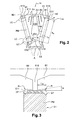
- Fig.3 details of a mounting of the PM permanent magnet at the beaks B1 and B2.
- This montage of the Fig.3 corresponds to a particular embodiment in which is provided an LM laminate.
- the LM laminate interposes between the upper face of the magnet PM and the lower faces of the nozzles B1, B2.
- the laminate LM is for example made of filled plastic, in a resin of epoxy resin type filled with glass fibers, a composite material or a deformable nonmagnetic metallic material.
- the function of the laminate to distribute the mechanical forces exerted on the top of the PM magnet and the beakers B1, B2 and to absorb by deformation a possible displacement of the magnet PM.
- the tests carried out by the inventive entity have shown that the centrifugal forces applying to the PM magnet can be significant. In the case where the machine is subjected to a very high speed of rotation, the magnet PM tends to move away from the axis of rotation.
- the LM laminate contributes to a better distribution of the mechanical stresses between the beakers B1, B2 and by absorbing by deformation a possible displacement of the magnet PM thus reduces the risk of a rupture of the magnet PM and / or deformation beakers B1, B2.
- the tests carried out have shown that a laminate thickness of at least 0.1 mm is desirable for it to perform its function correctly.
- an inclination angle ⁇ of the lower face of the spout B1, B2, with respect to the upper face of the magnet PM is also provided.
- a mechanical reinforcement obtained by means of a round radius R.
- This rounding is formed between the chamfered lower face of the spout B1, B2 and the adjoining face, substantially radial, forming an inner wall magnet housing.
- the radius R will preferably have a value between 0.2 and 0.9 times the depth L B of the beak B1, B2.
- chamfers or equivalent (rounded) CF are provided in this embodiment on the upper part of the magnet PM so as to avoid an edge contact of the magnet PM at the radius of radius R. will refer only to chamfers CF later in the description and in the appended claims, knowing that the term "chamfer” also covers equivalents such as rounded.
- the LM laminate allows a distribution of the mechanical forces on the two beakers B1 and B2 and can in some cases make unnecessary the need to chamfer the edges of PM magnets when its thickness is sufficient.
- the recess E1 comprises in its lower part, in the vicinity of the rotor shaft 11, reluctant spaces E12 which are, in this embodiment, spaces filled with air, left vacant by the magnet PM and which introducing a magnetic reluctance prevent local demagnetization of the PM magnet.
- the recesses E2 essentially have a reluctance and magnetic barrier function to control a magnetic defluxing flux through the central part of the rotor, i.e., in the magnetic mass between the bottom of the PM magnets and the shaft.
- a rotor It will be appreciated that these recesses E2 are filled with air in this particular embodiment. In some applications, they may be filled with non-magnetic or magnetic materials with a low relative permeability.
- the E3 recesses fulfill several functions. In general, their main function is to contribute, like the recesses E2, to the control of the magnetic defluxing flux, through the central part of the rotor, and to reduce the inertia of the rotor 11.
- these recesses E3 are filled with air. In some applications, they may also be filled with non-magnetic materials, even magnetic but with low density.
- the recesses E3 are shown here as being arranged radially in the rotor 11, centered between the consecutive magnets PM and symmetrical, it will be noted that in other embodiments of the invention, the recesses E3 can, especially in their upper part, being neither centered nor symmetrically shaped.
- other recesses are arranged in each pole, on either side of the recess E3.
- the recesses E4 contribute to reduce the inertia of the rotor 11 and are located in the alignment of the field lines, between them, so as to oppose as little as possible the passage of the magnetic flux of the magnets PM.
- the recesses E4 are two in number on each side of the recess E3.
- the number of recesses E4 may vary depending on the application and the available space. For example, their number may vary from 1 to 8, although 2 to 3 for the present invention is a good compromise.
- the practical rules for cutting the sheets make it necessary to keep a material width of between 1 and 2 times the thickness of the sheet, depending on the case.
- the minimum width of material to be preserved will be between 0.35 mm and 0.7 mm.
- the recess E3 comprises an upper trapezium E30 and a lower part E31.
- the upper trapezium E30 makes it possible to reduce the inertia of the rotor 11. It does, however, have an effect on the armature magnetic reaction and can also be dimensioned so as to participate in controlling it.
- the lower part E31 is the part of the recess E3 which contributes to the control of the magnetic flux of defluxing through the central part of the rotor 11.
- the part E31 together with the reluctant spaces E12 and the recess E2, makes it possible to control the path of the magnetic field lines in the central part of the rotor 11.
- the definition of the recesses E31 and E2 from the study of the distribution of the magnetic field lines in the pole makes it possible to obtain an optimally sized defluxing magnetic circuit.
- This magnetic deflowering circuit must be sized so as to allow a passage of the magnetic flux bypassing the magnet PM when a short-circuit situation occurs in the stator windings, or else when at high speed a current equal at most to the short-circuit current is injected into the stator windings so as to oppose the magnetic flux generated by the permanent magnets.
- Such a magnetic defluxing circuit prevents the appearance in the magnet PM of a demagnetizing field with an amplitude too high, likely to cause irreversible demagnetization of the PM magnet.
- the magnetic defluxing circuit must thus be calculated so as to obtain a correct polarization of the magnet PM.
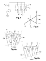
- FIG. Fig.4 The equivalent magnetic circuit around a permanent magnet PM, in a short-circuit situation in the stator windings, is represented in FIG. Fig.4 .
- the LC field lines (shown in FIG. Fig.2 ) of the magnet PM do not pass through the stator of the machine. These LC field lines then close again through a high magnetic reluctance Rh and low magnetic reluctances Rb1 and Rb2 of the magnetic circuit formed around the magnet PM.
- the high magnetic reluctance Rh is that of the path of the LC field lines through the beakers B1, B2 and the notch E10.
- the low magnetic reluctance Rb1 is that of the path of the LC field lines through the recesses E2 on either side of the bottom of the magnet PM, in the two adjacent poles.
- the low magnetic reluctance Rb2 is that of the LC field line paths through the ferrous constrictions S of the two poles, between the recesses E2 and the edges opposite the recesses E1.
- the constrictions formed by the portions B1, B2 and S operate globally in a saturation mode.
- the magnetic circuit comprises the FMM source in series with the internal reluctance R a and a magnetic flux reluctance R f substantially equivalent to the three reluctances Rh, Rb1 and Rb2 in parallel.
- the magnetization curve has substantially the shape of a straight line as shown in FIG. Fig.5 .
- B a is the magnetic induction of the magnet PM
- H a is the magnetic field applied to PM
- B r is the remanent magnetic induction of PM
- ⁇ a is the magnetic permeability of PM.
- ⁇ can be between 1.3 and 4.
- the zS in which, as shown in Fig.2 , l a is the width of the magnet PM, h a is the height of PM and L zs is the length of PM.
- ⁇ min and ⁇ max for each type of magnet. Then, knowing the reluctance R a PM magnets selected for the machine, a global deflux circuit reluctance R f can be determined from the inequality (12). Once the value of the overall deflection circuit reluctance R f has been determined, it is possible to optimize the distribution thereof between Rh, Rb1 and Rb2 so as to obtain the desired performances.
- the bridge BR is dimensionally defined by its height H and its length L.
- BR bridge is necessary for reasons of mechanical strength of the rotor 11.
- BR bridge is continuous over the entire axial length of the rotor 11, so that the recess E3 does not open at any point of the circumferential surface of the rotor 11.
- the bridge BR is made recessed relative to the circumferential surface of the rotor and a wider gap is obtained at the bridge BR between the stator 10 and the rotor 11.
- BR bridge may be performed discontinuously leaving the opening E3 opening on the outside, the circumferential surface of the rotor 11, for example, every other sheet.
- variable air gap between the rotor 11 and the stator 10, visible at Figs.1 , 6a and 6b also contributes to a reduction of harmonics and therefore iron losses.
- the height H of the bridge BR will be between about 1 times the thickness of the sheet and approximately 1 times the width of the magnet has.
- the height of the bridge BR according to the invention will be here between about 0.35 mm and about 5 mm.
- Figs.9 and 10 show curves of torque Cmax and of inertia I as a function of the length L of the bridge BR.
- the tests carried out by the inventive entity show that the best performance compromise between maximum torque and minimum inertia will be obtained for a length L of the BR bridge less than approximately 1.5 times the width I a (1xI a ) of the permanent magnets. PM.
- the minimum length L that the bridge BR may take will be of the order of 1.5 times the thickness of the sheet, ie approximately 0.520 mm for a sheet thickness of 0.35 mm.
- the invention has been described herein in the context of particular embodiments. The invention will find important applications in electric traction motors used in the automobile, for electric vehicles and hybrid vehicles. However, it should be clear that the invention will also find applications in other fields than the automotive field.
Abstract
Description
La présente invention concerne une machine électrique tournante synchrone à aimants permanents et concentration de flux. Plus particulièrement, l'invention concerne une machine électrique tournante de ce type pour des applications comme générateur ou moteur électrique de traction dans des véhicules automobiles électriques et hybrides.The present invention relates to a synchronous rotating electrical machine with permanent magnets and flux concentration. More particularly, the invention relates to a rotary electric machine of this type for applications as a generator or electric traction motor in electric and hybrid motor vehicles.
De par leurs performances accrues en termes de rendement et de puissance massique et volumique, les moteurs synchrones à aimants permanents trouvent aujourd'hui une large application dans le domaine de la traction dans les véhicules automobiles. De plus, la disponibilité d'aimants permanents aux terres rares à grande échelle et à des conditions économiques acceptables rend viable le choix de ces moteurs électriques pour les nouvelles générations de véhicules automobiles.Due to their increased performances in terms of efficiency and mass and volume power, permanent magnet synchronous motors are now widely used in the field of traction in motor vehicles. In addition, the availability of large-scale rare earth permanent magnets and acceptable economic conditions makes the choice of these electric motors viable for new generations of motor vehicles.
Ces moteurs électriques sont réalisables dans une large gamme de puissance et de vitesse et trouveront des applications aussi bien dans les véhicules tout électriques que dans les véhicules à bas CO2 de types dits « mild-hybrid » et « full-hybrid » (en terminologie anglaise).These electric motors are feasible in a wide range of power and speed and will find applications both in all-electric vehicles in vehicles with low CO 2 types called "mild-hybrid" and "full-hybrid" (Terminology English).
Les applications « mild-hybrid » concernent généralement des moteurs électriques de l'ordre de 8 à 10 KW, par exemple, un moteur électrique monté en face avant d'un moteur thermique et couplé à celui-ci par une courroie de transmission. Il est possible avec un tel moteur électrique de réduire la cylindrée de la motorisation thermique (« engine downsizing » en terminologie anglaise) en prévoyant une assistance électrique en couple qui fournit un appoint de puissance notamment lors des reprises. De plus, une traction à faible vitesse, par exemple en environnement urbain, peut également être assurée par ce même moteur électrique. Les applications de type « full-hybrid» concernent généralement des moteurs de 30 à 50 KW pour des architectures de type série et/ou parallèle avec un niveau d'intégration plus abouti du ou des moteurs électriques dans la chaîne de traction du véhicule."Mild-hybrid" applications generally relate to electric motors of the order of 8 to 10 KW, for example, an electric motor mounted on the front face of a heat engine and coupled thereto by a transmission belt. It is possible with such an electric motor to reduce the engine capacity of the engine ("engine downsizing" in English terminology) by providing a power assisted torque which provides extra power especially during rework. In addition, a low-speed traction, for example in urban environment, can also be provided by the same electric motor. "Full-hybrid" type applications generally concern motors from 30 to 50 kW for series and / or parallel type architectures with a more advanced integration level of the electric motor or motors in the vehicle's power train.
Parmi les différents moteurs synchrones à aimants permanents connus ceux du type à concentration de flux présentent un intérêt particulier du fait de leurs excellentes performances. Dans ces moteurs à concentration de flux, les aimants sont enterrés dans la masse magnétique du rotor et disposés selon une configuration sensiblement radiale.Of the various permanent magnet synchronous motors known, those of the flux concentration type are of particular interest because of their excellent performance. In these flux concentration motors, the magnets are buried in the magnetic mass of the rotor and arranged in a substantially radial configuration.
Dans un véhicule automobile, un moteur électrique utilisé en traction sur l'ensemble des missions de circulation du véhicule est soumis à des régimes de charge et de vitesse variables. Une stratégie de commande à couple maximal complétée par une stratégie de défluxage (dite également « stratégie de démagnétisation») pour atteindre la zone des hautes vitesses apparaît comme étant une bonne solution pour commander le moteur électrique. Cependant, le défluxage dans les moteurs à aimants permanents présente un risque de démagnétisation des aimants et cela d'autant plus que la température des aimants est élevée. Les moteurs à concentration de flux, de par la disposition de leurs aimants dans le rotor, sont particulièrement exposés à ce risque de démagnétisation.In a motor vehicle, an electric motor used in traction on all vehicle traffic missions is subject to variable load and speed regimes. A maximum torque control strategy supplemented by a defluxing strategy (also known as "demagnetization strategy") to reach the high speed zone appears to be a good solution for controlling the electric motor. However, the defluxing in the permanent magnet motors presents a risk of demagnetization of the magnets and this especially as the temperature of the magnets is high. Flow-concentrating motors, by the arrangement of their magnets in the rotor, are particularly exposed to this risk of demagnetization.
Il est donc souhaitable de proposer des machines électriques tournantes synchrones à aimants permanents et concentration de flux dans lesquelles le risque de désaimantation des aimants soit contrôlé voire totalement éliminé.It is therefore desirable to provide synchronous rotating electrical machines with permanent magnets and flux concentration in which the risk of magnet demagnetization is controlled or completely eliminated.
Selon un premier aspect, la présente invention concerne une machine électrique tournante comprenant un stator muni de bobinages statoriques et un rotor, le rotor comprenant une pluralité de pôles Nord et pôles Sud alternés qui sont formés à partir d'aimants permanents disposés selon une configuration sensiblement radiale dite à concentration de flux, les aimants permanents étant logés dans des premiers évidements respectifs aménagés dans la masse magnétique du rotor.According to a first aspect, the present invention relates to a rotating electrical machine comprising a stator provided with stator windings and a rotor, the rotor comprising a plurality of alternating North poles and South poles which are formed from permanent magnets arranged in a configuration substantially said radial flux concentration, the permanent magnets being housed in respective first recesses arranged in the magnetic mass of the rotor.
Conformément à l'invention, le rotor comporte au moins, pour chaque aimant permanent, un circuit magnétique de défluxage autorisant la circulation d'un flux magnétique de défluxage, le circuit magnétique de défluxage ayant une réluctance magnétique de circuit de défluxage déterminée en fonction d'une réluctance magnétique interne de l'aimant permanent de manière à ce que le rapport de la réluctance magnétique de circuit de défluxage sur la réluctance magnétique interne d'aimant soit compris dans un intervalle de valeurs prédéterminé, compris entre environ 0,3 et environ 3, garantissant l'aimant permanent contre tout risque de désaimantation lorsqu'un courant ayant une intensité égale à celle d'un courant de court-circuit de la machine est injecté dans les bobinages statoriques de manière à s'opposer au flux magnétique généré par les aimants permanents.According to the invention, the rotor comprises at least, for each permanent magnet, a magnetic deflowering circuit allowing the circulation of a magnetic flux of defluxing, the magnetic flux-loss circuit having a magnetic reluctance of a defluxing circuit determined according to an internal magnetic reluctance of the permanent magnet so that the ratio of the magnetic flux loop reluctance to the magnet internal magnetic reluctance is within a predetermined range of values, between about 0 , 3 and about 3, guaranteeing the permanent magnet against any risk of demagnetization when a current having an intensity equal to that of a short circuit current of the machine is injected into the stator windings so as to oppose the magnetic flux generated by permanent magnets.
De préférence, les aimants permanents sont de forme sensiblement rectangulaire.Preferably, the permanent magnets are of substantially rectangular shape.
Selon des formes particulières de réalisation de l'invention, les aimants permanents sont de type NdFeB et l'intervalle de valeurs prédéterminé est d'environ 0,7 à environ 1,5.According to particular embodiments of the invention, the permanent magnets are of NdFeB type and the predetermined range of values is from about 0.7 to about 1.5.
Selon une caractéristique particulière de l'invention, le circuit magnétique de défluxage comporte un deuxième évidement aménagé dans la masse magnétique du pôle magnétique correspondant, ce deuxième évidement étant situé dans une partie centrale inférieure du pôle, ce deuxième évidement étant centré sensiblement à égales distances entre des extrémités inférieures des deux aimants permanents radiaux consécutifs délimitant le pôle et ayant une première réluctance contribuant à la réluctance magnétique de circuit de défluxage.According to a particular characteristic of the invention, the magnetic deflowering circuit comprises a second recess arranged in the magnetic mass of the corresponding magnetic pole, this second recess being situated in a lower central part of the pole, this second recess being centered substantially at equal distances between lower ends of the two consecutive radial permanent magnets delimiting the pole and having a first reluctance contributing to the magnetic reluctance of the defluxing circuit.
Selon encore une autre caractéristique particulière de l'invention, le circuit magnétique de défluxage comporte un étranglement dans la masse magnétique du pôle magnétique correspondant, l'étranglement étant situé dans la partie centrale inférieure du pôle, entre une extrémité inférieure de l'aimant permanent correspondant et le deuxième évidement, et l'étranglement ayant une seconde réluctance contribuant à la réluctance magnétique de circuit de défluxage.According to yet another particular characteristic of the invention, the magnetic defluxing circuit comprises a constriction in the magnetic mass of the corresponding magnetic pole, the throat being located in the lower central part of the pole, between a lower end of the permanent magnet. corresponding and the second recess, and the throttle having a second reluctance contributing to the magnetic reluctance of the defluxing circuit.
Selon encore une autre caractéristique particulière de l'invention, le circuit magnétique de défluxage comporte une encoche dans la masse magnétique du rotor qui débouche à la circonférence extérieure de celui-ci et à l'intérieur du premier évidement formant logement d'aimant permanent, l'encoche étant sensiblement radiale et parallèle à l'axe du rotor, et l'encoche ayant une troisième réluctance contribuant à la réluctance magnétique de circuit de défluxage.According to yet another particular characteristic of the invention, the magnetic deflowering circuit comprises a notch in the magnetic mass of the rotor which opens at the outer circumference. thereof and within the first permanent magnet housing recess, the notch being substantially radial and parallel to the axis of the rotor, and the notch having a third reluctance contributing to the magnetic circuit reluctance of defluxing.
Selon encore une autre caractéristique particulière de l'invention, le premier évidement formant logement d'aimant permanent comporte dans sa partie basse, au moins un premier espace laissé vacant par l'aimant permanent et formant un premier espace réluctant qui s'oppose à une démagnétisation locale de l'aimant permanent au niveau de sa partie basse.According to yet another particular feature of the invention, the first permanent magnet housing recess comprises in its lower part, at least a first space left vacant by the permanent magnet and forming a first reluctant space which opposes a local demagnetization of the permanent magnet at its lower part.
Selon encore une autre caractéristique particulière de l'invention, le premier évidement formant logement d'aimant permanent comporte dans sa partie haute, au moins un deuxième espace laissé vacant par l'aimant permanent et formant un deuxième espace réluctant qui s'oppose à une démagnétisation locale de l'aimant permanent au niveau de sa partie haute.According to yet another particular characteristic of the invention, the first recess forming a permanent magnet housing comprises in its upper part, at least a second space left vacant by the permanent magnet and forming a second reluctant space which opposes a local demagnetization of the permanent magnet at its upper part.
Selon encore une autre caractéristique particulière de l'invention, le rotor comporte, dans chacun de ses pôles, un troisième évidement aménagé radialement dans la masse magnétique du pôle concerné, entre les deux aimants permanents consécutifs délimitant le pôle, le troisième évidement ayant une partie basse qui participe au contrôle du flux magnétique de défluxage à travers la partie centrale du rotor et une partie haute qui participe à une réduction de l'inertie mécanique du rotor.According to yet another particular characteristic of the invention, the rotor comprises, in each of its poles, a third recess arranged radially in the magnetic mass of the pole concerned, between the two consecutive permanent magnets delimiting the pole, the third recess having a portion bass which participates in the control of the magnetic flux of defluxing through the central part of the rotor and an upper part which contributes to a reduction of the mechanical inertia of the rotor.
D'autres caractéristiques et avantages de l'invention ressortiront à la lecture de la description suivante de plusieurs formes de réalisation particulières, en référence aux figures ci-dessous, dans lesquelles :
- la
Fig.1 montre, de manière simplifiée, la structure d'une forme de réalisation particulière d'une machine électrique tournante défluxable à aimants permanents et concentration de flux selon l'invention ; - la
Fig.2 montre les différents évidements réalisés dans la masse magnétique du rotor de la machine de laFig.1 ; - la
Fig.3 montre une configuration de montage des aimants permanents, intégrant une laminette, au niveau de l'extrémité haute des aimants ; - la
Fig.4 montre un réseau de réluctances d'un circuit magnétique de défluxage pour un aimant permanent du rotor de la machine de laFig.1 ; - la
Fig.5 est une courbe d'aimantation des aimants montrant le point de fonctionnement de ceux-ci à l'intersection de leur droite de charge ; - les
Figs.6a et 6b montrent respectivement des première et seconde réalisations d'une portion formant pont entre des masses magnétiques du rotor, de part et d'autre d'un évidement E3 ; - les
Figs.7 et 8 sont respectivement des courbes de couple et d'inertie en fonction d'une hauteur H de la portion formant pont desFigs.6a et 6b ; et - les
Figs.9 et 10 sont respectivement des courbes de couple de la machine et d'inertie du rotor en fonction d'une longueur L de la portion formant pont desFigs.6a et 6b .
- the
Fig.1 shows, in a simplified manner, the structure of a particular embodiment of a rotating permanent magnet rotating machine and flux concentration according to the invention; - the
Fig.2 shows the different recesses made in the magnetic mass of the rotor of the machine of theFig.1 ; - the
Fig.3 shows a mounting configuration of the permanent magnets, incorporating a laminette, at the high end of the magnets; - the
Fig.4 shows a network of reluctances of a magnetic circuit of defluxing for a permanent magnet of the rotor of the machine of theFig.1 ; - the
Fig.5 is a magnetization curve of magnets showing the operating point of magnets at the intersection of their load line; - the
Figs.6a and 6b respectively show first and second embodiments of a bridge portion between magnetic masses of the rotor, on either side of a recess E3; - the
Figs.7 and 8 are respectively curves of torque and inertia as a function of a height H of the bridge portion ofFigs.6a and 6b ; and - the
Figs.9 and 10 are respectively machine torque curves and rotor inertia as a function of a length L of the bridge portion of theFigs.6a and 6b .
La
Une réalisation concrète d'une telle machine selon l'invention est par exemple un moteur de traction de 8 à 10 KW pour des applications dans des véhicules automobiles du type dits «mild-hybrid». Une forme de réalisation particulière de ce moteur comprend un stator 10 ayant 60 encoches 101 et un rotor 11 comportant 10 pôles Nord et Sud alternés. Le rotor 11 a un diamètre de l'ordre 100 mm et une longueur axiale de l'ordre de 50 mm. Le rotor 11 comporte 10 aimants permanents PM ayant une forme sensiblement rectangulaire et pour dimensions : longueur (Lzs) x hauteur (ha) x largeur (la) = 50 mm x 25 mm x 5 mm.A concrete embodiment of such a machine according to the invention is for example a traction motor of 8 to 10 KW for applications in motor vehicles of the type called "mild-hybrid". A particular embodiment of this motor comprises a
Le stator 10 et le rotor 11 sont réalisés de manière classique avec des paquets de tôles métalliques formant des masses magnétiques.The
Les encoches 101 du stator 10 sont prévues pour recevoir des bobinages statoriques (non représentés) et forment entre elles une pluralité de dents statoriques. Selon les formes de réalisation, les encoches 101 seront prévues pour loger des bobinages concentrés, bobinés sur des grosses dents, ou bien des bobinages distribués.The
Le rotor 11 a la forme générale d'un cylindre multilobé, chacun des lobes correspondant à un pôle magnétique du rotor.The
Les aimants PM sont disposés de manière radiale de façon à obtenir une structure de rotor de type à concentration de flux. Dans certaines formes de réalisation, les aimants PM pourront être légèrement désaxés par rapport au rayon du rotor 11. Les aimants PM sont de préférence des aimants permanents comprenant des terres rares tels que des aimants de type Néodyme-Fer-Bore (NeFeB), Samarium-Fer (SmFe), Samarium-Cobalt (SmCo) ou bien des aimants obtenus à partir de ferrites frittés ou liés.The PM magnets are arranged radially so as to obtain a flux concentration type rotor structure. In some embodiments, the PM magnets may be slightly misaligned relative to the
Le rotor 10 comprend un alésage central débouchant à ses deux extrémités faciales et destiné à recevoir son arbre d'entraînement A. On notera que dans la présente invention l'arbre A pourra être réalisé dans un matériau magnétique ou amagnétique selon l'application envisagée.The
Le rotor 10 comprend également des évidements E1, E2 et E3 qui se répètent pour chaque pôle et s'étendent axialement sur sensiblement toute la longueur du rotor.The
Des tôles de fermeture, sans les évidements E1, E2 et E3, sont éventuellement prévues aux extrémités faciales du rotor 11 afin de contribuer à l'assemblage du rotor 11. Des points de soudure (non représentés) à la périphérie du paquet de tôles et des tirants traversants (non représentés), parallèles à l'axe central, sont également prévus pour l'assemblage du rotor 11. Les tirants traversants sont réalisés dans un matériau magnétique ou amagnétique, selon les applications. Avantageusement, le passage des tirants à travers le paquet de tôles du rotor 11 pourra se faire à travers les évidements E3.Closing plates, without the recesses E1, E2 and E3, are optionally provided at the facial ends of the
Dans cette forme de réalisation particulière, les évidements E1, E2 et E3 sont chacun au nombre de 10, ce nombre correspondant au nombre N=10 de pôles magnétiques du rotor 11.In this particular embodiment, the recesses E1, E2 and E3 are each 10 in number, this number corresponding to the number N = 10 of magnetic poles of the
Les évidements E1, E2 et E3 sont maintenant décrits de manière détaillée en référence également aux
Les évidements E1 forment des logements quasi-rectangulaires pour les aimants permanents PM. Les évidements E1 ne sont pas occupés entièrement par les aimants PM et comportent des parties laissées vacantes qui remplissent des fonctions de réluctance et de barrière magnétique pour contrôler le passage du flux magnétique dans la masse magnétique du rotor 11 et les aimants PM.The recesses E1 form quasi-rectangular housings for the PM permanent magnets. The recesses E1 are not occupied entirely by the PM magnets and have portions left vacant which perform reluctance and magnetic barrier functions to control the passage of the magnetic flux in the magnetic mass of the
L'évidement E1 débouche sur la circonférence extérieure du rotor 11 par l'intermédiaire d'une encoche E10. L'encoche E10 se prolonge axialement sur la longueur du rotor 11 et délimite ainsi le pôle par rapport au pôle voisin. Il est ainsi formé dans les pôles adjacents des premier et second becs B1, B2, qui sont en regard et destinés à retenir l'aimant permanent PM dans son logement, en s'opposant à l'effet de la force centrifuge sur l'aimant PM.The recess E1 opens on the outer circumference of the
Un espace réluctant E11 est également prévu entre le bord haut de l'aimant PM et la face inférieure des becs B1, B2. Cet espace réluctant E11 est un espace de l'évidement E1 laissé vacant par l'aimant PM.A reluctant space E11 is also provided between the top edge of the magnet PM and the underside of the nozzles B1, B2. This reluctant space E11 is a space of the recess E1 left vacant by the magnet PM.
Il est montré à la
La laminette LM s'interpose entre la face supérieure de l'aimant PM et les faces inférieures des becs B1, B2. La laminette LM est par exemple réalisée en plastique chargé, dans une résine de type résine époxy chargée en fibres de verre, un matériau composite ou un matériau métallique amagnétique déformable. La laminette pour fonction de répartir les efforts mécaniques s'exerçant sur le haut de l'aimant PM et les becs B1, B2 et d'absorber par déformation un éventuel déplacement de l'aimant PM. Les essais effectués par l'entité inventive ont montrés que les forces centrifuges s'appliquant sur l'aimant PM peuvent être importantes. Dans le cas où la machine est soumise à une vitesse de rotation très élevée, l'aimant PM a tendance à s'éloigner de l'axe de rotation du rotor 11, sous l'effet de la force centrifuge, et une déformation des becs B1, B2 vers l'extérieur du rotor 11 pourrait survenir. La laminette LM contribue à une meilleure répartition des contraintes mécaniques entre les becs B1, B2 et en absorbant par déformation un éventuel déplacement de l'aimant PM réduit ainsi le risque d'une rupture de l'aimant PM et/ou d'une déformation des becs B1, B2. Les essais réalisés ont montrés qu'une épaisseur de laminette d'au moins 0,1 mm est souhaitable pour que celle-ci remplisse correctement sa fonction.The LM laminate interposes between the upper face of the magnet PM and the lower faces of the nozzles B1, B2. The laminate LM is for example made of filled plastic, in a resin of epoxy resin type filled with glass fibers, a composite material or a deformable nonmagnetic metallic material. The function of the laminate to distribute the mechanical forces exerted on the top of the PM magnet and the beakers B1, B2 and to absorb by deformation a possible displacement of the magnet PM. The tests carried out by the inventive entity have shown that the centrifugal forces applying to the PM magnet can be significant. In the case where the machine is subjected to a very high speed of rotation, the magnet PM tends to move away from the axis of rotation. rotation of the
Conformément à l'invention, il est également prévu un angle d'inclinaison α de la face inférieure du bec B1, B2, par rapport à la face supérieure de l'aimant PM. Cette inclinaison pourra par exemple être obtenue au moyen d'un chanfrein qui selon l'application aura un angle compris entre α = 0,1 ° et α = 15°.According to the invention, there is also provided an inclination angle α of the lower face of the spout B1, B2, with respect to the upper face of the magnet PM. This inclination may for example be obtained by means of a chamfer which according to the application will have an angle between α = 0.1 ° and α = 15 °.
De préférence, comme montré à la
Les essais réalisés par l'entité inventive ont montré que pour la classe de machines auxquelles s'applique l'invention, un angle α et un rayon R dans les plages indiquées ci-dessus permettent d'obtenir des résultats satisfaisants en termes d'optimum de tenue aux forces centrifuges s'exerçant dans la gamme de vitesses allant de 0 à 20000 tours/mn.The tests carried out by the inventive entity have shown that for the class of machines to which the invention applies, an angle α and a radius R in the ranges indicated above make it possible to obtain satisfactory results in terms of optimum resistance to centrifugal forces acting in the range of speeds from 0 to 20000 revolutions / min.
La laminette LM autorise une distribution des efforts mécaniques sur les deux becs B1 et B2 et peut dans certains cas rendre inutile la nécessité de chanfreiner les bords des aimants PM lorsque son épaisseur est suffisante.The LM laminate allows a distribution of the mechanical forces on the two beakers B1 and B2 and can in some cases make unnecessary the need to chamfer the edges of PM magnets when its thickness is sufficient.
On notera que les réluctances magnétiques introduites par l'encoche E10 et l'espace réluctant E11, outre le fait de participer à la polarisation générale de l'aimant PM, décrite ultérieurement, s'opposent à une démagnétisation locale de l'aimant PM au niveau des arêtes.It will be noted that the magnetic reluctances introduced by the notch E10 and the reluctant space E11, in addition to participating in the general polarization of the magnet PM, described later, oppose a local demagnetization of the magnet PM to level of edges.
Comme cela apparaît plus particulièrement à la
Les évidements E2 ont essentiellement une fonction de réluctance et de barrière magnétique pour contrôler un flux magnétique de défluxage à travers la partie centrale du rotor, c'est-à-dire, dans la masse magnétique entre le bas des aimants PM et l'arbre A du rotor. On notera que ces évidements E2 sont remplis d'air dans cette forme de réalisation particulière. Dans certaines applications, ils pourront être remplis avec des matériaux amagnétiques ou magnétiques avec une faible perméabilité relative.The recesses E2 essentially have a reluctance and magnetic barrier function to control a magnetic defluxing flux through the central part of the rotor, i.e., in the magnetic mass between the bottom of the PM magnets and the shaft. A rotor. It will be appreciated that these recesses E2 are filled with air in this particular embodiment. In some applications, they may be filled with non-magnetic or magnetic materials with a low relative permeability.
Les évidements E3 remplissent plusieurs fonctions. De manière générale, ils ont essentiellement pour fonction de contribuer, comme les évidements E2, au contrôle du flux magnétique de défluxage, à travers la partie centrale du rotor, et de réduire l'inertie du rotor 11. Dans cette forme de réalisation, comme les encoches E10, les espaces réluctants E11, E12 et les évidements E2, ces évidements E3 sont remplis d'air. Dans certaines applications, ils pourront aussi être remplis avec des matériaux amagnétiques, voire magnétiques mais avec une faible densité.The E3 recesses fulfill several functions. In general, their main function is to contribute, like the recesses E2, to the control of the magnetic defluxing flux, through the central part of the rotor, and to reduce the inertia of the
Bien que les évidements E3 soient représentés ici comme étant aménagés radialement dans le rotor 11, centrés entre les aimants PM consécutifs et de forme symétrique, on notera que dans d'autres formes de réalisation de l'invention, les évidements E3 peuvent, notamment dans leur partie haute, n'être ni centrés ni de forme symétrique.Although the recesses E3 are shown here as being arranged radially in the
Comme montré notamment à la
Par ailleurs, on notera que les règles pratiques de découpe des tôles imposent de garder une largeur de matière comprise selon les cas entre 1 et 2 fois l'épaisseur de la tôle. En d'autres termes, cela signifie, par exemple, qu'entre deux évidements voisins du rotor ou entre un évidement et une circonférence extérieure du rotor, il doit au moins rester une largeur de matière comprise entre 1 et 2 fois l'épaisseur de la tôle. Ainsi, par exemple, pour une tôle de 0,35 mm d'épaisseur, la largeur minimale de matière à conserver sera comprise entre 0,35 mm et 0,7 mm.Moreover, it should be noted that the practical rules for cutting the sheets make it necessary to keep a material width of between 1 and 2 times the thickness of the sheet, depending on the case. In other words, this means, for example, that between two adjacent recesses of the rotor or between a recess and an outer circumference of the rotor, it must at least remain a material width of between 1 and 2 times the thickness of the rotor. prison. Thus, for example, for a sheet of 0.35 mm thick, the minimum width of material to be preserved will be between 0.35 mm and 0.7 mm.
Dans cette forme de réalisation, l'évidement E3 comporte un trapèze supérieur E30 et une partie basse E31. De manière générale, le trapèze supérieur E30 permet de réduire l'inertie du rotor 11. Il a cependant un effet sur la réaction magnétique d'induit et peut aussi être dimensionné de manière à participer au contrôle de celle-ci. La partie basse E31 est la partie de l'évidement E3 qui participe au contrôle du flux magnétique de défluxage à travers la partie centrale du rotor 11. La partie E31, conjointement avec les espaces réluctants E12 et l'évidement E2, permet de contrôler le trajet des lignes de champ magnétique dans la partie centrale du rotor 11.In this embodiment, the recess E3 comprises an upper trapezium E30 and a lower part E31. Generally speaking, the upper trapezium E30 makes it possible to reduce the inertia of the
Conformément à l'invention, la définition des évidements E31 et E2 à partir de l'étude de la répartition des lignes de champ magnétique dans le pôle permet d'obtenir un circuit magnétique de défluxage dimensionné de manière optimale. Ce circuit magnétique de défluxage doit être dimensionné de manière à permettre un passage du flux magnétique contournant l'aimant PM lorsque apparaît une situation de court-circuit dans les bobinages statoriques, ou bien lorsque en haute vitesse un courant égal au maximum au courant de court-circuit est injecté dans les bobinages statoriques de manière à s'opposer au flux magnétique généré par les aimants permanents.According to the invention, the definition of the recesses E31 and E2 from the study of the distribution of the magnetic field lines in the pole makes it possible to obtain an optimally sized defluxing magnetic circuit. This magnetic deflowering circuit must be sized so as to allow a passage of the magnetic flux bypassing the magnet PM when a short-circuit situation occurs in the stator windings, or else when at high speed a current equal at most to the short-circuit current is injected into the stator windings so as to oppose the magnetic flux generated by the permanent magnets.
Un tel circuit magnétique de défluxage empêche l'apparition dans l'aimant PM d'un champ démagnétisant avec une amplitude trop élevée, susceptible d'entraîner une démagnétisation irréversible de l'aimant PM. Le circuit magnétique de défluxage doit ainsi être calculé de manière à obtenir une polarisation correcte de l'aimant PM.Such a magnetic defluxing circuit prevents the appearance in the magnet PM of a demagnetizing field with an amplitude too high, likely to cause irreversible demagnetization of the PM magnet. The magnetic defluxing circuit must thus be calculated so as to obtain a correct polarization of the magnet PM.
Le circuit magnétique équivalent autour d'un aimant permanent PM, en situation de court-circuit dans les bobinages statoriques, est représenté à la
En situation de court-circuit dans les bobinages statoriques, les lignes de champ LC (montrées à la
La réluctance magnétique haute Rh est celle du trajet des lignes de champ LC à travers les becs B1, B2 et l'encoche E10. La réluctance magnétique basse Rb1 est celle du trajet des lignes de champ LC à travers les évidements E2 de part et d'autre du bas de l'aimant PM, dans les deux pôles adjacents. La réluctance magnétique basse Rb2 est celle des trajets des lignes de champ LC à travers les étranglements ferreux S des deux pôles, entre les évidements E2 et les bords en regard des évidements E1.The high magnetic reluctance Rh is that of the path of the LC field lines through the beakers B1, B2 and the notch E10. The low magnetic reluctance Rb1 is that of the path of the LC field lines through the recesses E2 on either side of the bottom of the magnet PM, in the two adjacent poles. The low magnetic reluctance Rb2 is that of the LC field line paths through the ferrous constrictions S of the two poles, between the recesses E2 and the edges opposite the recesses E1.
Les étranglements formés par les portions B1, B2 et S fonctionnent globalement dans un mode de saturation.The constrictions formed by the portions B1, B2 and S operate globally in a saturation mode.
Comme montré à la
En référence également à la
Pour les aimants permanents modernes, par exemple de type NdFeB, la courbe d'aimantation a sensiblement la forme d'une droite telle que montrée à la ![]()
dans laquelle, Ba est l'induction magnétique de l'aimant PM, Ha est le champ magnétique appliqué à PM, Br est l'induction magnétique rémanente de PM et µa est la perméabilité magnétique de PM.For modern permanent magnets, for example of the NdFeB type, the magnetization curve has substantially the shape of a straight line as shown in FIG. ![]()
where B a is the magnetic induction of the magnet PM, H a is the magnetic field applied to PM, B r is the remanent magnetic induction of PM and μ a is the magnetic permeability of PM.
Les essais effectués par l'entité inventive ont montrés que pour éviter une désaimantation irréversible de l'aimant PM, il est souhaitable d'avoir un point de fonctionnement P satisfaisant à l'égalité : ![]()
avec λ compris entre une valeur minimum λmin et une valeur maximum λmax, qui, pour des aimants PM de type NdFeB, ont été déterminées égales à :
- λmin = 1,7 et
- λmax = 2,5
with λ between a minimum value λ min and a maximum value λ max , which for PM magnets of NdFeB type have been determined equal to:
- λ min = 1.7 and
- λ max = 2.5
De manière plus générale, selon le type d'aimant, λ pourra être compris entre 1,3 et 4.More generally, depending on the type of magnet, λ can be between 1.3 and 4.
La valeur voisine de λ = 2 apparaît comme étant un bon compromis en situation de court-circuit pour un aimant PM.The value close to λ = 2 appears to be a good compromise in a short-circuit situation for a PM magnet.
Pour simplifier, on considère ici que la perméabilité µa de l'aimant PM est sensiblement égale à la perméabilité absolue µo = 4.π.10-7 H/m.For simplicity, here we consider that the permeability μ of the magnet PM is substantially equal to the absolute permeability μ o = 4.π.10 -7 H / m.
La réluctance d'un aimant rectangulaire tel que l'aimant PM est donnée approximativement par la formule: ![]()
dans laquelle, comme montré à la ![]()
in which, as shown in
Le champ coercitif Hc produisant une désaimantation définitive de l'aimant PM est donné en première approximation par : ![]()
![]()
Le flux magnétique φa généré par l'aimant PM est donné par le produit de l'induction magnétique et de la surface, soit: ![]()
![]()
Le flux magnétique φa est également donné par la relation : ![]()
![]()
La force magnétomotrice de l'aimant PM est donnée en première approximation par : ![]()
![]()
A partir des égalités (5), (6) et (7), on obtient l'égalité : ![]()
![]()
Il découle de l'égalité (8) : ![]()
![]()
En introduisant les égalités (2) et (3) dans (9), on obtient : ![]()
![]()
Il en découle la relation : ![]()
![]()
Sachant que λ doit être compris entre λmin et λmax, on obtient l'inégalité : ![]()
![]()
Pour les aimants PM de type NdFeB, avec λmin = 1,7 et λmax = 2,5, on obtient l'inégalité : ![]()
![]()
De manière plus générale, selon le type d'aimant, on obtient l'inégalité : ![]()
![]()
De préférence, on choisira Rf/Ra = 1 qui correspond à λ = 2.Preferably, one will choose R f / R a = 1 which corresponds to λ = 2.
Conformément à l'invention, il est possible de déterminer des valeurs λmin et λmax pour chaque type d'aimant. Ensuite, connaissant la réluctance Ra des aimants PM choisis pour la machine, une réluctance de circuit de défluxage globale Rf peut être déterminée à partir de l'inégalité (12). Une fois la valeur de la réluctance de circuit de défluxage globale Rf déterminée, il est possible d'optimiser la répartition de celle-ci entre Rh, Rb1 et Rb2 de manière à obtenir les performances voulues.According to the invention, it is possible to determine values λ min and λ max for each type of magnet. Then, knowing the reluctance R a PM magnets selected for the machine, a global deflux circuit reluctance R f can be determined from the inequality (12). Once the value of the overall deflection circuit reluctance R f has been determined, it is possible to optimize the distribution thereof between Rh, Rb1 and Rb2 so as to obtain the desired performances.
En référence maintenant aux
Les essais effectués par l'entité inventive ont montré que le dimensionnement de ce pont BR du paquet de tôles rotoriques est important pour, d'une part, réduire le moment d'inertie du rotor 11 et, d'autre part, pour être en mesure de garantir l'obtention du couple maximum voulu pour la machine.The tests carried out by the inventive entity have shown that the dimensioning of this bridge BR of the rotor plate package is important for, on the one hand, reducing the moment of inertia of the
Comme cela apparaît aux
Un tel pont BR est nécessaire pour des raisons de tenue mécanique du rotor 11. Dans les formes de réalisation des
On notera que la forme de réalisation de la
En référence aux
Comme le montre la
Sur un plan pratique, compte tenu des règles de découpe des tôles indiquées plus haut dans la description, la hauteur H du pont BR sera comprise entre environ 1 fois l'épaisseur de la tôle et environ 1 fois la largeur d'aimant la. Ainsi, par exemple, avec des tôles ayant une épaisseur de 0,35 mm et des aimants ayant une largeur de 5 mm, la hauteur du pont BR selon l'invention sera comprise ici entre environ 0,35 mm et environ 5 mm.In practical terms, considering the cutting rules sheets indicated above in the description, the height H of the bridge BR will be between about 1 times the thickness of the sheet and approximately 1 times the width of the magnet has. Thus, for example, with sheets having a thickness of 0.35 mm and magnets having a width of 5 mm, the height of the bridge BR according to the invention will be here between about 0.35 mm and about 5 mm.
Les
L'invention a été décrite ici dans le cadre de formes de réalisation particulières. L'invention trouvera des applications importantes dans les moteurs électriques de traction utilisés dans l'automobile, pour les véhicules électriques et les véhicules hybrides. Cependant, il doit être clair que l'invention trouvera aussi des applications dans d'autres domaines que le domaine de l'automobile.The invention has been described herein in the context of particular embodiments. The invention will find important applications in electric traction motors used in the automobile, for electric vehicles and hybrid vehicles. However, it should be clear that the invention will also find applications in other fields than the automotive field.
Claims (9)
Applications Claiming Priority (1)
| Application Number | Priority Date | Filing Date | Title |
|---|---|---|---|
| FR1052448A FR2958465B1 (en) | 2010-03-31 | 2010-03-31 | SYNCHRONOUS ROTATING ELECTRIC MACHINE WITH PERMANENT MAGNETS AND FLOW CONCENTRATION |
Publications (2)
| Publication Number | Publication Date |
|---|---|
| EP2372872A2 true EP2372872A2 (en) | 2011-10-05 |
| EP2372872A3 EP2372872A3 (en) | 2016-10-05 |
Family
ID=43332487
Family Applications (1)
| Application Number | Title | Priority Date | Filing Date |
|---|---|---|---|
| EP11156749.1A Withdrawn EP2372872A3 (en) | 2010-03-31 | 2011-03-03 | Synchronous rotating electric machine with permanent magnets and flux concentration |
Country Status (5)
| Country | Link |
|---|---|
| US (1) | US8669682B2 (en) |
| EP (1) | EP2372872A3 (en) |
| JP (1) | JP2011217601A (en) |
| CN (1) | CN102208854B (en) |
| FR (1) | FR2958465B1 (en) |
Cited By (6)
| Publication number | Priority date | Publication date | Assignee | Title |
|---|---|---|---|---|
| FR2982439A1 (en) * | 2011-11-08 | 2013-05-10 | Valeo Equip Electr Moteur | ROTOR OF ROTATING ELECTRIC MACHINE AND ROTATING ELECTRIC MACHINE COMPRISING SUCH A ROTOR |
| FR3009140A1 (en) * | 2013-07-29 | 2015-01-30 | Valeo Equip Electr Moteur | ROTOR WITH PERMANENT MAGNETS |
| EP2722970A3 (en) * | 2012-10-18 | 2017-08-30 | Robert Bosch Gmbh | Rotor arrangement for an electric machine with permanent magnet excitation |
| GB2494898B (en) * | 2011-09-21 | 2017-10-25 | Cummins Generator Tech Ltd | Rotating electrical machine |
| WO2019052862A1 (en) * | 2017-09-18 | 2019-03-21 | IFP Energies Nouvelles | Isthmi for the magnetic bridges of an electric machine rotor |
| FR3080718A1 (en) * | 2018-04-26 | 2019-11-01 | Valeo Equipements Electriques Moteur | ROTATING ELECTRIC MACHINE HAVING A CONFIGURATION REDUCING THE HARMONICS OF THE THIRD ORDER |
Families Citing this family (21)
| Publication number | Priority date | Publication date | Assignee | Title |
|---|---|---|---|---|
| JP5708181B2 (en) * | 2010-05-12 | 2015-04-30 | 株式会社デンソー | Rotating electrical machine rotor |
| US9080279B2 (en) * | 2011-10-24 | 2015-07-14 | Lg Electronics Inc. | Washing machine to produce three-dimensional motion |
| KR101951423B1 (en) | 2012-10-09 | 2019-04-25 | 엘지전자 주식회사 | A sub-drum structure of a washing machine having a dual-drum and an assembling method of a sub-drum |
| US9512551B2 (en) | 2011-10-24 | 2016-12-06 | Lg Electronics Inc. | Washing machine to produce three-dimensional motion |
| FR2983658B1 (en) | 2011-12-01 | 2014-09-12 | Valeo Equip Electr Moteur | ROTOR OF ROTATING ELECTRIC MACHINE AND ROTATING ELECTRIC MACHINE COMPRISING SUCH A ROTOR |
| JP5858232B2 (en) * | 2012-02-17 | 2016-02-10 | 日本電産株式会社 | Rotor core, motor, and motor manufacturing method |
| JP5972607B2 (en) * | 2012-03-02 | 2016-08-17 | アイチエレック株式会社 | Electric motor |
| WO2013168295A1 (en) * | 2012-05-11 | 2013-11-14 | 株式会社安川電機 | Rotating electrical machine |
| JP2014075901A (en) * | 2012-10-04 | 2014-04-24 | Samsung Electronics Co Ltd | Brushless motor and method for manufacturing rotor used for the same |
| WO2014104819A1 (en) * | 2012-12-28 | 2014-07-03 | 주식회사 효성 | Rotor of interior permanent magnet motor having structure for preventing permanent magnet from escaping |
| KR20140140185A (en) * | 2013-05-28 | 2014-12-09 | 삼성전자주식회사 | Motor |
| FR3013529B1 (en) * | 2013-11-20 | 2017-04-14 | Valeo Equip Electr Moteur | BLINDS FOR MAINTAINING MAGNETS |
| JP2015104244A (en) * | 2013-11-26 | 2015-06-04 | ファナック株式会社 | Rotor having resin hole for resin filling and manufacturing method of rotor |
| US9692266B2 (en) * | 2014-07-22 | 2017-06-27 | GM Global Technology Operations LLC | Spoke-type PM machine with bridge |
| US9641037B2 (en) * | 2014-08-28 | 2017-05-02 | General Electric Company | Stator slot liners |
| JP6328598B2 (en) * | 2015-10-22 | 2018-05-23 | ファナック株式会社 | Synchronous motor permanent magnet rotor |
| DE102017005415A1 (en) * | 2017-06-09 | 2018-12-27 | Volkswagen Aktiengesellschaft | Synchronous machine with magnetic flux deflection |
| CN112994288B (en) * | 2019-12-12 | 2022-06-14 | 中车永济电机有限公司 | Permanent magnet motor rotor magnetic circuit topological structure |
| JP7281674B2 (en) * | 2020-02-20 | 2023-05-26 | パナソニックIpマネジメント株式会社 | motors and power tools |
| FR3115639B1 (en) * | 2020-10-22 | 2023-04-21 | Ifp Energies Now | Synchro-reluctant electric machine with open tangential bridges |
| WO2023105701A1 (en) * | 2021-12-09 | 2023-06-15 | 株式会社 東芝 | Rotor of rotary electric machine |
Family Cites Families (13)
| Publication number | Priority date | Publication date | Assignee | Title |
|---|---|---|---|---|
| US4339874A (en) * | 1978-12-26 | 1982-07-20 | The Garrett Corporation | Method of making a wedge-shaped permanent magnet rotor assembly |
| US4302693A (en) * | 1978-12-26 | 1981-11-24 | The Garrett Corporation | Wedge shaped permanent magnet rotor assembly with magnet cushions |
| US4568846A (en) * | 1983-10-28 | 1986-02-04 | Welco Industries | Permanent magnet laminated rotor with conductor bars |
| JPH05344668A (en) * | 1992-06-08 | 1993-12-24 | Fanuc Ltd | Rotor of synchronous motor |
| DE19723302A1 (en) * | 1997-06-04 | 1998-12-10 | Sen Rainer Born | Permanent magnet system with reluctance support for rotors of electrical machines |
| FR2784816B1 (en) * | 1998-10-20 | 2001-01-05 | Valeo Equip Electr Moteur | ROTATING ELECTRIC MACHINE HAVING A NEW ARRANGEMENT OF ROTOR EXCITATION BY PERMANENT MAGNETS |
| DE102005060116A1 (en) * | 2004-12-20 | 2006-07-06 | Danfoss Compressors Gmbh | Rotor for an electric motor |
| JP4815967B2 (en) * | 2005-09-21 | 2011-11-16 | トヨタ自動車株式会社 | Permanent magnet rotating electric machine |
| KR101092321B1 (en) * | 2005-12-21 | 2011-12-09 | 주식회사 동서전자 | Rotor of a line start permanent magnet synchronous motor |
| WO2008137709A2 (en) * | 2007-05-04 | 2008-11-13 | A. O. Smith Corporation | Interior permanent magnet motor and rotor |
| US7800272B2 (en) * | 2007-11-28 | 2010-09-21 | Asmo Co., Ltd. | Embedded magnet motor and manufacturing method of the same |
| JP5161612B2 (en) * | 2008-02-22 | 2013-03-13 | 株式会社東芝 | Permanent magnet type rotating electrical machine, method for assembling permanent magnet type rotating electrical machine, and method for disassembling permanent magnet type rotating electrical machine |
| EP2270957A4 (en) * | 2008-03-19 | 2011-09-07 | Sanyo Electric Co | Permanent magnet synchronization motor |
-
2010
- 2010-03-31 FR FR1052448A patent/FR2958465B1/en active Active
-
2011
- 2011-03-03 EP EP11156749.1A patent/EP2372872A3/en not_active Withdrawn
- 2011-03-30 JP JP2011073920A patent/JP2011217601A/en not_active Withdrawn
- 2011-03-30 US US13/076,266 patent/US8669682B2/en active Active
- 2011-03-31 CN CN201110081032.5A patent/CN102208854B/en active Active
Non-Patent Citations (1)
| Title |
|---|
| None |
Cited By (12)
| Publication number | Priority date | Publication date | Assignee | Title |
|---|---|---|---|---|
| GB2494898B (en) * | 2011-09-21 | 2017-10-25 | Cummins Generator Tech Ltd | Rotating electrical machine |
| FR2982439A1 (en) * | 2011-11-08 | 2013-05-10 | Valeo Equip Electr Moteur | ROTOR OF ROTATING ELECTRIC MACHINE AND ROTATING ELECTRIC MACHINE COMPRISING SUCH A ROTOR |
| WO2013068675A3 (en) * | 2011-11-08 | 2013-10-17 | Valeo Equipements Electriques Moteur | Rotor for a rotary electric machine, and rotary electric machine including such a rotor |
| EP2722970A3 (en) * | 2012-10-18 | 2017-08-30 | Robert Bosch Gmbh | Rotor arrangement for an electric machine with permanent magnet excitation |
| FR3009140A1 (en) * | 2013-07-29 | 2015-01-30 | Valeo Equip Electr Moteur | ROTOR WITH PERMANENT MAGNETS |
| WO2015015084A3 (en) * | 2013-07-29 | 2015-10-15 | Valeo Equipements Electriques Moteur | Rotor with permanent magnets |
| US10008891B2 (en) | 2013-07-29 | 2018-06-26 | Valeo Equipements Electriques Moteur | Rotor with permanent magnets |
| WO2019052862A1 (en) * | 2017-09-18 | 2019-03-21 | IFP Energies Nouvelles | Isthmi for the magnetic bridges of an electric machine rotor |
| FR3071370A1 (en) * | 2017-09-18 | 2019-03-22 | IFP Energies Nouvelles | ISTHMA OF MAGNETIC BRIDGES OF AN ELECTRIC MACHINE ROTOR |
| CN111226375A (en) * | 2017-09-18 | 2020-06-02 | Ifp新能源公司 | Isthmus for a magnetic bridge of a rotor of an electric machine |
| CN111226375B (en) * | 2017-09-18 | 2022-07-19 | 马威动力控制技术(上海)有限公司 | Isthmus for a magnetic bridge of a rotor of an electric machine |
| FR3080718A1 (en) * | 2018-04-26 | 2019-11-01 | Valeo Equipements Electriques Moteur | ROTATING ELECTRIC MACHINE HAVING A CONFIGURATION REDUCING THE HARMONICS OF THE THIRD ORDER |
Also Published As
| Publication number | Publication date |
|---|---|
| FR2958465A1 (en) | 2011-10-07 |
| CN102208854A (en) | 2011-10-05 |
| US8669682B2 (en) | 2014-03-11 |
| FR2958465B1 (en) | 2013-02-15 |
| CN102208854B (en) | 2014-07-09 |
| US20110316378A1 (en) | 2011-12-29 |
| JP2011217601A (en) | 2011-10-27 |
| EP2372872A3 (en) | 2016-10-05 |
Similar Documents
| Publication | Publication Date | Title |
|---|---|---|
| EP2372873B1 (en) | Synchronous rotating electric machine with permanent magnets and flux concentration | |
| EP2372872A2 (en) | Synchronous rotating electric machine with permanent magnets and flux concentration | |
| EP2786469B1 (en) | Rotor for a rotary electric machine and rotary electric machine comprising such a rotor | |
| EP2786470B1 (en) | Rotor for a rotary electric machine and rotary electric machine comprising such a rotor | |
| WO2013060960A2 (en) | Rotor for a rotating electric machine and rotating electrical machine comprising a rotor | |
| EP2599197B1 (en) | Synchronous rotary electric machine having hybrid-excitation rotor | |
| EP2622715B1 (en) | Rotating electric synchronous machine with double-excitation rotor | |
| EP2792053B1 (en) | Rotary electric machine rotor and rotary electric machine comprising such a rotor | |
| FR3006824A1 (en) | ROTOR OF ROTATING ELECTRIC MACHINE AND ROTATING ELECTRIC MACHINE COMPRISING SUCH A ROTOR | |
| EP2372874B1 (en) | Synchronous rotating electric machine with permanent magnets and flux concentration | |
| WO2015185847A2 (en) | Flux-concentrating rotor with permanent magnets for rotary electric machine | |
| EP2599196B1 (en) | Synchronous rotary electric machine having a double excitation rotor | |
| EP3229348B1 (en) | Rotor for an electrical machine | |
| EP2777135B1 (en) | Rotor for a rotary electric machine, and rotary electric machine including such a rotor | |
| EP2599198B1 (en) | Synchronous rotary electric machine having a hybrid-excitation rotor | |
| EP2128962A2 (en) | Rotating electric machine with magnets included in the rotor | |
| EP2600500A2 (en) | Rotor of a rotating electric machine and rotating electric machine comprising such a rotor | |
| WO2014006294A1 (en) | Rotating electric machine with compensation of armature magnetic feedback | |
| FR2963504A1 (en) | Double-excitation rotating electrical machine e.g. electric traction motor of electric vehicle, has excitation coils inserted in radial polar teeth, where width of polar teeth is in specific range |
Legal Events
| Date | Code | Title | Description |
|---|---|---|---|
| PUAI | Public reference made under article 153(3) epc to a published international application that has entered the european phase |
Free format text: ORIGINAL CODE: 0009012 |
|
| 17P | Request for examination filed |
Effective date: 20110303 |
|
| AK | Designated contracting states |
Kind code of ref document: A2 Designated state(s): AL AT BE BG CH CY CZ DE DK EE ES FI FR GB GR HR HU IE IS IT LI LT LU LV MC MK MT NL NO PL PT RO RS SE SI SK SM TR |
|
| AX | Request for extension of the european patent |
Extension state: BA ME |
|
| PUAL | Search report despatched |
Free format text: ORIGINAL CODE: 0009013 |
|
| AK | Designated contracting states |
Kind code of ref document: A3 Designated state(s): AL AT BE BG CH CY CZ DE DK EE ES FI FR GB GR HR HU IE IS IT LI LT LU LV MC MK MT NL NO PL PT RO RS SE SI SK SM TR |
|
| AX | Request for extension of the european patent |
Extension state: BA ME |
|
| RIC1 | Information provided on ipc code assigned before grant |
Ipc: H02K 1/27 20060101AFI20160826BHEP Ipc: H02K 21/14 20060101ALI20160826BHEP |
|
| 17Q | First examination report despatched |
Effective date: 20171018 |
|
| STAA | Information on the status of an ep patent application or granted ep patent |
Free format text: STATUS: THE APPLICATION IS DEEMED TO BE WITHDRAWN |
|
| 18D | Application deemed to be withdrawn |
Effective date: 20180301 |