EP2372339A2 - Quantitative evaluation of scratch-induced damages on polymeric and coating materials - Google Patents
Quantitative evaluation of scratch-induced damages on polymeric and coating materials Download PDFInfo
- Publication number
- EP2372339A2 EP2372339A2 EP10172070A EP10172070A EP2372339A2 EP 2372339 A2 EP2372339 A2 EP 2372339A2 EP 10172070 A EP10172070 A EP 10172070A EP 10172070 A EP10172070 A EP 10172070A EP 2372339 A2 EP2372339 A2 EP 2372339A2
- Authority
- EP
- European Patent Office
- Prior art keywords
- scratch
- damage
- test specimen
- polymeric
- coating materials
- Prior art date
- Legal status (The legal status is an assumption and is not a legal conclusion. Google has not performed a legal analysis and makes no representation as to the accuracy of the status listed.)
- Granted
Links
Images
Classifications
-
- G—PHYSICS
- G01—MEASURING; TESTING
- G01N—INVESTIGATING OR ANALYSING MATERIALS BY DETERMINING THEIR CHEMICAL OR PHYSICAL PROPERTIES
- G01N3/00—Investigating strength properties of solid materials by application of mechanical stress
- G01N3/40—Investigating hardness or rebound hardness
- G01N3/42—Investigating hardness or rebound hardness by performing impressions under a steady load by indentors, e.g. sphere, pyramid
- G01N3/46—Investigating hardness or rebound hardness by performing impressions under a steady load by indentors, e.g. sphere, pyramid the indentors performing a scratching movement
-
- G—PHYSICS
- G01—MEASURING; TESTING
- G01N—INVESTIGATING OR ANALYSING MATERIALS BY DETERMINING THEIR CHEMICAL OR PHYSICAL PROPERTIES
- G01N21/00—Investigating or analysing materials by the use of optical means, i.e. using sub-millimetre waves, infrared, visible or ultraviolet light
- G01N21/84—Systems specially adapted for particular applications
- G01N21/88—Investigating the presence of flaws or contamination
Definitions
- the present invention is related to a method for quantitative evaluation of scratch-induced damage on polymeric and coating materials, and in particular, to a method allowing quantitative evaluation of damage caused by mar and scratch on the surface of polymeric and coating materials.
- ISO 19252 evaluates scratch-induced surface damage, based on the apparent shape of the trace of a scratch tip, such as ploughing, wedge formation, and cutting.
- the critical normal load is not a normalized value. They are scratch tip geometry dependent. In other words, a new value (i.e., material property) that normalized by the corresponding contact area, similar to the definition of yield stress (N/m 2 ) and impact resistance (J/m), needs to be expressed to quantify the whitening point and the initiation of cutting. Therefore, there are some problems on the reproducibility, objectivity, reliability and discrimination of results. In this context, the critical normal load is not appropriate as a factor of the quantification.
- the present invention was made to solve the foregoing problems of the existing evaluation method of scratch-induced surface damage formed on the surface of polymeric and coating materials.
- the present invention is provided with a method for quantitative evaluation of scratch-induced damage on polymeric and coating materials having superiority in objectivity, reliability, reproducibility, or the like, in which a scratch is made using a scratch tip capable of area-contact or line-contact with a material surface in order to measure or analyze the degree of surface damage caused by the scratch through a scratch test under a constant load condition, and the degree of surface damage is represented by corresponding color coordinates or color difference to give a quantitated result.
- the present invention provides a method for quantitative evaluation of scratch-induced damage formed on the surface of polymeric and coating materials, including: preparing a test specimen of polymeric and coating materials; inducing a scratch damage on the surface of the test specimen; representing the scratch damage formed on the test specimen as corresponding color coordinates; and calculating a quantitated scratch damage index from a combination of a load applied to the surface of the test specimen and the color coordinates corresponding to the scratch damage.
- the scratch damage may be formed on the surface of the test specimen using a scratch tip capable of area-contact or line-contact.
- the scratch damage may be formed by applying a constant load to the surface of the test specimen.
- the step of representing the scratch damage as corresponding color coordinates comprises steps of: obtaining an image by scanning the scratch damage formed on the surface of the test specimen; and representing color values of the obtained image as color coordinates of a 2-dimensional (2D) or 3D color model using a color analysis software.
- the step of representing the scratch damage as corresponding color coordinates is conducted by using a color analysis profiler.
- a color analysis technique using a 2D or 3D color model may be used to analyze the scratch damage formed on the surface of the test specimen.
- the scratch damage may be in a form of simple damage, in which scratches are formed along one direction, or be in a form of complex damage, in which further scratches having another direction with the simple damage is added to the simple damaged test specimen.
- the color analysis software may be one capable of performing color analysis as a whole or as a part of the surface damage area of the test specimen.
- the color analysis software is capable of performing continuous measurement on the width and length of the whole scratch formed on the surface of the test specimen.
- the color analysis software may represent the color coordinates of each row j of the image corresponding to the scratch direction as an average value of all the color coordinate values of the row j.
- the scratch damage index is calculated on the basis of degree of scratch damage ( ⁇ D) and scratch strength ( S ⁇ s ).
- the scratch damage index is calculated on the basis of degree of scratch damage ( ⁇ D) and scratch resistance ( R ⁇ s ).
- the method for quantitative evaluation of scratch-induced damage on polymeric and coating materials allows evaluation of a degree of scratch-induced surface damage formed on the material surface as a quantitated value. By providing objectivity, it can reduce evaluation errors resulting from the operator or the evaluation environment. Accordingly, a reliable evaluation of scratch resistance is ensured.
- the method according to the present invention allows an objective evaluation of scratch-induced surface damage of polymeric and coating materials by representing the degree of scratch-induced damage as a quantitated scratch damage index (SDI).
- SDI quantitated scratch damage index
- the present invention provides a method for quantitative evaluation of mar- or scratch-induced damage formed on the surface of polymeric and coating materials, in which a scratch damage is formed under a constant load condition using a scratch tip capable of line-contact or line-contact with a material surface.
- the degree of the scratch damage is represented as color difference or color coordinates, and a quantitated scratch damage index (SDI) is calculated from a combination of the color difference or color coordinates and a load applied to the material surface.
- SDI quantitated scratch damage index
- polymeric and coating materials refer to polymeric materials and coating materials formed on the surface of various materials.
- the polymeric and/or coating material will be simply referred to as "material”.
- a test specimen of the selected material is prepared first. Then, a scratch damage is intentionally induced on the surface of the test specimen.
- a conventional scratch generator may be used to induce the scratch damage.
- YMT-2 Center for Tribology, Inc. was used as the scratch generator.
- the scratch generator has a scratch tip capable of being in area-contact or line-contact with the material surface.
- the scratch tip may be made of a material having hardness greater than that of the polymeric and coating materials, for example, metal, mineral or inorganic material.
- the scratch tip contacts with the material surface under a constant load condition and acts to apply a stress to form a scratch.
- the surface damage induced by the scratch tip may be two types.
- the first type is a simple damage, in which scratches or mars are formed along one direction on the material surface by the scratch tip.
- the other type is a complex damage, in which further scratches or mars having another direction with the simple damage is added to the simple damaged surface.
- the method according to the present invention evaluates both types of scratch damage.
- the complex scratch damage may be formed by inducing a scratch damage along a longitudinal direction on a material surface on which a scratch damage has been already induced along a transverse direction.
- FIG. 2 schematically shows scratch damages intentionally induced on a material surface using a scratch tip according to an embodiment of the present invention
- the scratch tip is applied with a constant load on the material surface so as to induce a mar or scratch.
- the contact portion of the scratch tip may have a polygonal shape, e.g. triangular or rectangular shape, or circular shape as shown in FIG. 3.
- a digitized image of the surface damage area is obtained, for example, using a scanner.
- the surface damage area is scanned at a 24-bit color scale with a resolution of 600 * 600 dpi or better to obtain a clear and distinct image of the material surface.
- Perfection V700 Photo (Epson) may be used to obtain the image.
- the color analysis software may be a software capable of obtaining color coordinates using various 2-dimensional or 3-dimensional color models.
- degree of the scratch-induced damage on the material surface and scratch resistance of the material may be evaluated using the software.
- the commercially available color analysis software QWin is used and the analysis result is represented as color coordinates of RGB and HSI 3-dimensional color models.
- the color coordinates are composed of three components to express color for each pixel of the scanned (digitized) image.
- the color coordinate is represented with red (R), green (G) and blue (B) values
- R red
- G green
- B blue
- I intensity
- the color analysis software is one capable of performing continuous measurement on the width and length of the whole scratch formed on the material surface as well as arbitrary selective measurement on the damage area.
- the color analysis software may represent the color coordinates of each row j of the image corresponding to the scratch direction as an average value of all the color coordinate values of the row j, for the whole or arbitrarily selected damaged area of the material surface.
- the color analysis software may classify the pixels of the image along the scratch direction for the whole or arbitrarily selected area into different rows j and represent the color coordinates of each row j of the image corresponding to the scratch direction as an average value of all the color coordinate values of the row j.
- the surface damage instead of scanning the damage area of the material surface, the surface damage may be directly represented as color difference or color coordinates using a color analysis profiler such as a spectrocolorimeter, a colorimeter, a color reader, or the like.
- a color analysis profiler such as a spectrocolorimeter, a colorimeter, a color reader, or the like.
- the color difference is represented as the difference in color coordinates between the area where the mar or scratch was formed and the other area.
- CM-3700d spectrocolorimeter Konica Minolta
- the color analysis using the spectrocolorimeter is performed under a standard condition of D65 standard illuminant, d/8 diffuse illumination and specular component excluded (SCE) mode, for objective and reasonable measurement.
- SCE specular component excluded
- a scratch damage index is calculated as a quantitated value of the scratch-induced surface damage.
- the scratch damage index is represented by degree of scratch damage ( ⁇ D), scratch strength ( S ⁇ s ) and scratch resistance ( R ⁇ s ).
- the representation may be different depending on the kind of the scratch tip. For example, if the scratch tip contacts the material surface with a constant area, i.e. area-contact, the scratch damage index may be represented by [ ⁇ D, S ⁇ s ]. And, if the scratch tip contacts linearly with the material surface, i.e. line-contact, it may be represented by [ ⁇ D, R ⁇ s ] .
- the degree of scratch damage ( ⁇ D) is calculated as the Euclidean distance between the color coordinates of the scratch-induced portion x and the intact portion y to give a quantitated value of the scratch-induced surface damage.
- the distance between the two portions is calculated by Equation 1.
- the scratch strength ( S ⁇ s ) and the scratch resistance ( R ⁇ s ) are calculated by Equations 2 and 3.
- the scratch force ( F ⁇ s )applied to the surface is defined as the summation of two orthogonal vectors, normal load ( F ⁇ n ) and resulting tangential load ( F ⁇ t ) as shown in Equation 4.
- the normal load ( F ⁇ n ) is a load applied by the scratch tip in a direction perpendicular to the material surface
- the tangential load ( F ⁇ t ) is a load applied by the scratch tip in a direction parallel to the material surface.
- F ⁇ s F ⁇ n + F ⁇ t
- FIG. 4 graphically shows the raw data obtained from a scratch test under a constant load condition according to an embodiment of the present invention.
- the thickness of the test specimen there is no specific limitation on the thickness of the test specimen.
- a plate-type test specimen having a thickness 10 mm or smaller and a length 70 mm or longer is preferred.
- a 3-mm thick, plate-type polypropylene composite material was used as a test specimen for evaluation of scratch damage.
- a 50-mm long scratch was formed along one direction on the test specimen using a scratch generator.
- the scratching speed (the speed at which the scratch damage was formed) was fixed at 1 mm/s, and the load to form the scratch was varied at 10 N, 20 N and 30 N.
- the scratch tip to form the scratch on the test specimen was that of FIG. 3 (A) (a) or (B).
- area-contact a scratch tip having the shape of FIG. 3 (A)(a) and contacting with the test specimen with a contact diameter of 1 mm and a contact area of 0.785 mm 2 was used.
- line-contact one having the shape of FIG. 3 (B) and contacting with the test specimen with a contact length of 1 mm was used.
- FIG. 5 shows digitized images of the mar- and scratch-induced simple damages obtained using the flatbed scanner.
- FIG. 6 schematically shows the color coordinate values of the RGB and HSI color models
- FIG. 7 graphically shows the color analysis result of Example 1 using the RGB and HSI color models in 2 dimensions.
- the color analysis result (mean and standard deviation) of FIG. 7 is given in Table 1.
- the method for evaluation of the scratch-induced surface damage according to the present invention gives the degree of surface damage as a digitized value.
- control means a test condition with no scratch damage formed.
- Table 1 Test condition Area-contact Line-contact RGB HSI RGB HSI G m R m I m S m G m R m I m S m Control 40 ⁇ 1.8 30 ⁇ 1.8 40 ⁇ 1.8 63 ⁇ 3.1 40 ⁇ 1.8 30 ⁇ 1.8 40 ⁇ 1.8 63 ⁇ 3.1 10N 40 ⁇ 1.3 32 ⁇ 1.4 40 ⁇ 1.2 63 ⁇ 2.5 56 ⁇ 2.2 46 ⁇ 2.2 56 ⁇ 2.2 47 ⁇ 2.4 20 N 44 ⁇ 2.3 34 ⁇ 2.3 43 ⁇ 1.9 59 ⁇ 1.8 89 ⁇ 6.3 79 ⁇ 6.2 88 ⁇ 4.5 31 ⁇ 2.0 30 N 105 ⁇ 6.3 95 ⁇ 6.2 105 ⁇ 6.3 25 ⁇ 1.8 136 ⁇ 6.9 126 ⁇ 7.1 138 ⁇ 5.9 19 ⁇ 1.8
- FIG. 8 shows digitized images of the complex damages obtained using a flatbed scanner.
- (a) is the image when no scratch damage was formed on the surface of the test specimen
- (b) is the image when a scratch damage was formed by applying a load of 10 N
- (c) is the image obtained when a scratch damage was formed by applying a load of 20 N.
- the degree of mar and scratch by the complex damage may also be quantitated using a color analysis software after scanning the complex damage area to obtain an image.
- Table 3 shows the degree of the damage of the surface of the test specimen by the complex damage as mean and standard deviation of the color difference ( L).
- Table 3 Test condition Area-contact L (change in lightness) Control - 10 N 2.7 ⁇ 0.4 20 N 4.5 ⁇ 0.4
- Example 1 The scratch-induced surface damage analysis in Example 1 gives objective and quantitated values, with less evaluation errors resulting from the operator or the evaluation environment and high reliability and reproducibility.
- the present invention provides a method for quantitative evaluation of mar- or scratch-induced damage formed on the surface of polymeric and coating materials, whereby a scratch damage is intentionally formed using a scratch tip capable of line-contact or line-contact with a material surface, the degree of the scratch damage is represented as color difference or color coordinates after obtaining a digitized image of the surface damage area by scanning and using a color analysis software or using a color analysis profiler such as a spectrocolorimeter, a colorimeter or a color reader without acquisition of the digitized image, and a quantitated scratch damage index is calculated therefrom.
- the present invention allows quantitative evaluation of the scratch-induced surface damage.
- the present invention is applicable without regard to the color or surface pattern of the material surface. And, the operator may randomly select the color model for analysis of the surface damage without limitation.
Landscapes
- General Health & Medical Sciences (AREA)
- General Physics & Mathematics (AREA)
- Life Sciences & Earth Sciences (AREA)
- Chemical & Material Sciences (AREA)
- Analytical Chemistry (AREA)
- Biochemistry (AREA)
- Immunology (AREA)
- Physics & Mathematics (AREA)
- Health & Medical Sciences (AREA)
- Pathology (AREA)
- Spectrometry And Color Measurement (AREA)
- Investigating Materials By The Use Of Optical Means Adapted For Particular Applications (AREA)
- Testing Resistance To Weather, Investigating Materials By Mechanical Methods (AREA)
- Sampling And Sample Adjustment (AREA)
Abstract
Description
- The present invention is related to a method for quantitative evaluation of scratch-induced damage on polymeric and coating materials, and in particular, to a method allowing quantitative evaluation of damage caused by mar and scratch on the surface of polymeric and coating materials.
- Recently, there are significant interests in improving scratch damages of polymeric and coating materials because they are more susceptible to scratch damages on the surface than metals. In general, scratches are regarded as visible surface damages and grooves that the human eyes can perceive. It is well known that a number of factors such as scratch mode, scratch velocity, surface hardness, surface roughness, temperature, scratch tip geometry, fillers and additives have effects on the scratch behaviors. Especially, although mar and scratch-induced damages on the material surface are visually perceivable, it is rather troublesome to accurately and quantitatively evaluate the surface damage.
- The current evaluation standards including ASTM (D7027-05) and ISO (19252:2008) introduce quantitative evaluation of scratch-induced surface damage of materials. But, these standard methods emphasize only the methodological aspects of scratch formation based on experiments.
- For example, ISO 19252 evaluates scratch-induced surface damage, based on the apparent shape of the trace of a scratch tip, such as ploughing, wedge formation, and cutting.
- However, since such a surface damage evaluation method is subjective and dependent on the competency of the observer, the obtained results may be not reproducible, meaningful while not ensuring objectivity.
- Mars occur when a relatively low load is applied to a material surface. If the load is increased beyond a certain limit, whitening phenomenon occurs. According to ASTM D7027-05, the normal load at this time point, referred to as a critical normal load, is measured to quantitatively evaluate the surface damage.
- However, since the critical normal load is not a normalized value. They are scratch tip geometry dependent. In other words, a new value (i.e., material property) that normalized by the corresponding contact area, similar to the definition of yield stress (N/m2) and impact resistance (J/m), needs to be expressed to quantify the whitening point and the initiation of cutting. Therefore, there are some problems on the reproducibility, objectivity, reliability and discrimination of results. In this context, the critical normal load is not appropriate as a factor of the quantification.
- Accordingly, a more effective and quantitative evaluation method for evaluating scratch-induced surface damage of a material is required.
- The present invention was made to solve the foregoing problems of the existing evaluation method of scratch-induced surface damage formed on the surface of polymeric and coating materials. The present invention is provided with a method for quantitative evaluation of scratch-induced damage on polymeric and coating materials having superiority in objectivity, reliability, reproducibility, or the like, in which a scratch is made using a scratch tip capable of area-contact or line-contact with a material surface in order to measure or analyze the degree of surface damage caused by the scratch through a scratch test under a constant load condition, and the degree of surface damage is represented by corresponding color coordinates or color difference to give a quantitated result.
- In one aspect, the present invention provides a method for quantitative evaluation of scratch-induced damage formed on the surface of polymeric and coating materials, including: preparing a test specimen of polymeric and coating materials; inducing a scratch damage on the surface of the test specimen; representing the scratch damage formed on the test specimen as corresponding color coordinates; and calculating a quantitated scratch damage index from a combination of a load applied to the surface of the test specimen and the color coordinates corresponding to the scratch damage.
- Preferably, the scratch damage may be formed on the surface of the test specimen using a scratch tip capable of area-contact or line-contact.
- Preferably, the scratch damage may be formed by applying a constant load to the surface of the test specimen.
- Preferably, the step of representing the scratch damage as corresponding color coordinates comprises steps of: obtaining an image by scanning the scratch damage formed on the surface of the test specimen; and representing color values of the obtained image as color coordinates of a 2-dimensional (2D) or 3D color model using a color analysis software.
- More preferably, the step of representing the scratch damage as corresponding color coordinates is conducted by using a color analysis profiler.
- Preferably, a color analysis technique using a 2D or 3D color model may be used to analyze the scratch damage formed on the surface of the test specimen.
- Preferably, the scratch damage may be in a form of simple damage, in which scratches are formed along one direction, or be in a form of complex damage, in which further scratches having another direction with the simple damage is added to the simple damaged test specimen.
- Preferably, the color analysis software may be one capable of performing color analysis as a whole or as a part of the surface damage area of the test specimen.
- Preferably, the color analysis software is capable of performing continuous measurement on the width and length of the whole scratch formed on the surface of the test specimen.
- Preferably, when a scratch tip is in line-contact with the surface of the test specimen, the color analysis software may represent the color coordinates of each row j of the image corresponding to the scratch direction as an average value of all the color coordinate values of the row j.
- In case of area-contact between the scratch tip and the surface of the test specimen, the scratch damage index is calculated on the basis of degree of scratch damage (ΔD) and scratch strength (
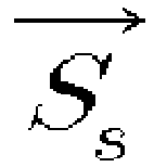

- The method for quantitative evaluation of scratch-induced damage on polymeric and coating materials according to the present invention allows evaluation of a degree of scratch-induced surface damage formed on the material surface as a quantitated value. By providing objectivity, it can reduce evaluation errors resulting from the operator or the evaluation environment. Accordingly, a reliable evaluation of scratch resistance is ensured.
- Further, the method according to the present invention allows an objective evaluation of scratch-induced surface damage of polymeric and coating materials by representing the degree of scratch-induced damage as a quantitated scratch damage index (SDI).
- Other features and aspects will be apparent from the following detailed description, the drawings, and the claims.
- The above and other objects, features and advantages of the present invention will become apparent from the following description of preferred embodiments given in conjunction with the accompanying drawings, in which:
-
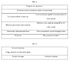
FIG. 1 is a flow diagram comparing a method for quantitative evaluation of scratch-induced damage according to an embodiment of the present invention with an existing evaluation method; -
FIG. 2 shows scratches intentionally induced on a material surface under a constant load condition according to an embodiment of the present invention; - FIG. 3 shows a scratch tip used in an embodiment of the present invention;
- FIG. 4 graphically shows the raw data obtained from a scratch test under a constant load condition according to an embodiment of the present invention;
- FIG. 5 shows digitized images of simple damages obtained using a flatbed scanner according to an embodiment of the present invention;
- FIG. 6 shows 3-dimensional color models and the range of color coordinate values according to an embodiment of the present invention;
- FIG. 7 graphically shows color analysis result according to an embodiment of the present invention;
- FIG. 8 shows digitized images of complex damages obtained using a flatbed scanner according to an embodiment of the present invention;
- The advantages, features and aspects of the present invention will become apparent from the following description of the embodiments with reference to the accompanying drawings, which is set forth hereinafter. The present invention may, however, be embodied in different forms and should not be construed as limited to the embodiments set forth herein. Rather, these embodiments are provided so that this disclosure will be thorough and complete, and will fully convey the scope of the present invention to those skilled in the art. The terminology used herein is for the purpose of describing particular embodiments only and is not intended to be limiting of example embodiments. As used herein, the singular forms "a", "an" and "the" are intended to include the plural forms as well, unless the context clearly indicates otherwise. It will be further understood that the terms "comprises" and/or "comprising", when used in this specification, specify the presence of stated features, integers, steps, operations, elements, and/or components, but do not preclude the presence or addition of one or more other features, integers, steps, operations, elements, components, and/or groups thereof.
- The present invention provides a method for quantitative evaluation of mar- or scratch-induced damage formed on the surface of polymeric and coating materials, in which a scratch damage is formed under a constant load condition using a scratch tip capable of line-contact or line-contact with a material surface. The degree of the scratch damage is represented as color difference or color coordinates, and a quantitated scratch damage index (SDI) is calculated from a combination of the color difference or color coordinates and a load applied to the material surface.
- As used herein, the term polymeric and coating materials refer to polymeric materials and coating materials formed on the surface of various materials. Hereinafter, the polymeric and/or coating material will be simply referred to as "material".
- As illustrated in
FIG. 1 , in order to evaluate scratch resistance against a stress applied to a material surface under a constant load condition via a scratch test, a test specimen of the selected material is prepared first. Then, a scratch damage is intentionally induced on the surface of the test specimen. - A conventional scratch generator may be used to induce the scratch damage. In an embodiment of the present invention, YMT-2 (Center for Tribology, Inc.) was used as the scratch generator.
- The scratch generator has a scratch tip capable of being in area-contact or line-contact with the material surface. Preferably, the scratch tip may be made of a material having hardness greater than that of the polymeric and coating materials, for example, metal, mineral or inorganic material.
- In an embodiment of the present invention, the scratch tip contacts with the material surface under a constant load condition and acts to apply a stress to form a scratch.
- The surface damage induced by the scratch tip may be two types. The first type is a simple damage, in which scratches or mars are formed along one direction on the material surface by the scratch tip. The other type is a complex damage, in which further scratches or mars having another direction with the simple damage is added to the simple damaged surface. The method according to the present invention evaluates both types of scratch damage.
- As illustrated in
FIG. 2 , the complex scratch damage may be formed by inducing a scratch damage along a longitudinal direction on a material surface on which a scratch damage has been already induced along a transverse direction. -
FIG. 2 schematically shows scratch damages intentionally induced on a material surface using a scratch tip according to an embodiment of the present invention; - Through area-contact or line-contact with the surface, the scratch tip is applied with a constant load on the material surface so as to induce a mar or scratch. If area-contact is desired, the contact portion of the scratch tip may have a polygonal shape, e.g. triangular or rectangular shape, or circular shape as shown in FIG. 3.
- In an embodiment of the present invention, after the surface damage is induced on the surface of the test specimen, a digitized image of the surface damage area is obtained, for example, using a scanner.
- Preferably, the surface damage area is scanned at a 24-bit color scale with a resolution of 600 * 600 dpi or better to obtain a clear and distinct image of the material surface. In an embodiment of the present invention, Perfection V700 Photo (Epson) may be used to obtain the image.
- Thus obtained digital image of the surface damage area of the scratched test specimen is analyzed using a color analysis software.
- The color analysis software may be a software capable of obtaining color coordinates using various 2-dimensional or 3-dimensional color models. In an embodiment of the present invention, degree of the scratch-induced damage on the material surface and scratch resistance of the material may be evaluated using the software.
- In an embodiment of the present invention, the commercially available color analysis software QWin is used and the analysis result is represented as color coordinates of RGB and HSI 3-dimensional color models.
- The color coordinates are composed of three components to express color for each pixel of the scanned (digitized) image. For example, in an RGB color model, the color coordinate is represented with red (R), green (G) and blue (B) values, and in an HSI color model, it is represented with hue (H), saturation (S) and intensity (I) values.
- Preferably, the color analysis software is one capable of performing continuous measurement on the width and length of the whole scratch formed on the material surface as well as arbitrary selective measurement on the damage area.
- Preferably, when the scratch tip is in line-contact with the surface of the test specimen, the color analysis software may represent the color coordinates of each row j of the image corresponding to the scratch direction as an average value of all the color coordinate values of the row j, for the whole or arbitrarily selected damaged area of the material surface.
- More specifically, the color analysis software may classify the pixels of the image along the scratch direction for the whole or arbitrarily selected area into different rows j and represent the color coordinates of each row j of the image corresponding to the scratch direction as an average value of all the color coordinate values of the row j.
- In an embodiment of the present invention, instead of scanning the damage area of the material surface, the surface damage may be directly represented as color difference or color coordinates using a color analysis profiler such as a spectrocolorimeter, a colorimeter, a color reader, or the like.
- The color difference is represented as the difference in color coordinates between the area where the mar or scratch was formed and the other area.
- In an embodiment of the present invention, a CM-3700d spectrocolorimeter (Konica Minolta) may be used.
- Preferably, the color analysis using the spectrocolorimeter is performed under a standard condition of D65 standard illuminant, d/8 diffuse illumination and specular component excluded (SCE) mode, for objective and reasonable measurement.
- Base on the color difference or color coordinates, a scratch damage index is calculated as a quantitated value of the scratch-induced surface damage.
- The scratch damage index is represented by degree of scratch damage (ΔD), scratch strength (


- Here, the degree of scratch damage (ΔD) is calculated as the Euclidean distance between the color coordinates of the scratch-induced portion x and the intact portion y to give a quantitated value of the scratch-induced surface damage. The distance between the two portions is calculated by Equation 1. The scratch strength (


wherein A is the contact area between the scratch tip and the material surface, and l is the contact length between the scratch tip and the material surface. - The scratch force (


- Here, the normal load (


- FIG. 4 graphically shows the raw data obtained from a scratch test under a constant load condition according to an embodiment of the present invention.
- In the present invention, there is no specific limitation on the thickness of the test specimen. However, a plate-type test specimen having a thickness 10 mm or smaller and a length 70 mm or longer is preferred.
- The examples and experiments will now be described. The following examples and experiments are for illustrative purposes only and not intended to limit the scope of this disclosure.
- A 3-mm thick, plate-type polypropylene composite material was used as a test specimen for evaluation of scratch damage.
- A 50-mm long scratch was formed along one direction on the test specimen using a scratch generator. The scratching speed (the speed at which the scratch damage was formed) was fixed at 1 mm/s, and the load to form the scratch was varied at 10 N, 20 N and 30 N.
- The scratch tip to form the scratch on the test specimen was that of FIG. 3 (A) (a) or (B). In case of area-contact, a scratch tip having the shape of FIG. 3 (A)(a) and contacting with the test specimen with a contact diameter of 1 mm and a contact area of 0.785 mm2 was used. In case of line-contact, one having the shape of FIG. 3 (B) and contacting with the test specimen with a contact length of 1 mm was used.
- After the surface damage was formed on the surface of the test specimen, a digital image was obtained using a flatbed scanner.
- FIG. 5 shows digitized images of the mar- and scratch-induced simple damages obtained using the flatbed scanner.
- In this example, about 90% of the total width of the scratch was arbitrarily selected, and color analysis was performed using two 3-dimensional color models of RGB and HSI.
- FIG. 6 schematically shows the color coordinate values of the RGB and HSI color models, and FIG. 7 graphically shows the color analysis result of Example 1 using the RGB and HSI color models in 2 dimensions. The color analysis result (mean and standard deviation) of FIG. 7 is given in Table 1.
- As shown in Table 1, as the constant load applied to the test specimen increased, so did the color coordinate values of the RGB color model. In contrast, in the HSI color model, the intensity (Im) and the saturation (Sm) values showed opposite behaviors with the increase of the constant load. That is to say, as the constant load applied to the test specimen increased, the intensity (Im) value increased but the saturation (Sm) decreased.
- From a combination of the color coordinates presented in Table 1 with the applied load, the quantitated scratch damage index (SDI)' was calculated and given in Table 2.
- As seen from Tables 1 and 2, the method for evaluation of the scratch-induced surface damage according to the present invention gives the degree of surface damage as a digitized value.
- In Tables 1 and 3 that follow, "control" means a test condition with no scratch damage formed.
Table 1 Test condition Area-contact Line-contact RGB HSI RGB HSI G m R m I m S m G m R m I m S m Control 40±1.8 30±1.8 40±1.8 63±3.1 40±1.8 30±1.8 40±1.8 63±3.1 10N 40±1.3 32±1.4 40±1.2 63±2.5 56±2.2 46±2.2 56±2.2 47±2.4 20 N 44±2.3 34±2.3 43±1.9 59±1.8 89±6.3 79±6.2 88±4.5 31±2.0 30 N 105±6.3 95±6.2 105±6.3 25±1.8 136±6.9 126±7.1 138±5.9 19±1.8 
- First, 20 simple damages were formed on the test specimen with 3 mm intervals along a transverse direction using a scratch tip capable of line-contact with the material surface. Then, 20 scratch damages were formed with 3 mm intervals in a longitudinal direction to induce complex damages.
- FIG. 8 shows digitized images of the complex damages obtained using a flatbed scanner. (a) is the image when no scratch damage was formed on the surface of the test specimen, (b) is the image when a scratch damage was formed by applying a load of 10 N, and (c) is the image obtained when a scratch damage was formed by applying a load of 20 N.
- After the complex damages were induced on the test specimen as in FIG. 8, D65 standard illuminant, d/8 diffuse illumination, specular component excluded modecolor analysis was performed using a spectrocolorimeter under a condition of D65 standard illuminant, d/8 diffuse illumination and specular component excluded (SCE) mode. A measuring mirror having a diameter of 25.4 mm was used. Then, the degree of the damage of the surface of the test specimen by the complex damage was represented as color difference ( L) by comparing the color coordinates of scratched portion with those of intact portion, using the L*a*b* color model.

- Of course, as in the simple damage, the degree of mar and scratch by the complex damage may also be quantitated using a color analysis software after scanning the complex damage area to obtain an image.
- Table 3 shows the degree of the damage of the surface of the test specimen by the complex damage as mean and standard deviation of the color difference ( L).
Table 3 Test condition Area-contact L (change in lightness) Control - 10 N 2.7±0.4 20 N 4.5±0.4 - The scratch-induced surface damage analysis in Example 1 gives objective and quantitated values, with less evaluation errors resulting from the operator or the evaluation environment and high reliability and reproducibility.
- As described above, the present invention provides a method for quantitative evaluation of mar- or scratch-induced damage formed on the surface of polymeric and coating materials, whereby a scratch damage is intentionally formed using a scratch tip capable of line-contact or line-contact with a material surface, the degree of the scratch damage is represented as color difference or color coordinates after obtaining a digitized image of the surface damage area by scanning and using a color analysis software or using a color analysis profiler such as a spectrocolorimeter, a colorimeter or a color reader without acquisition of the digitized image, and a quantitated scratch damage index is calculated therefrom.
- By performing color analysis on the surface of polymeric and coating materials on which scratch damage is formed and providing the evaluation result as a quantitated scratch damage index, the present invention allows quantitative evaluation of the scratch-induced surface damage.
- The present invention is applicable without regard to the color or surface pattern of the material surface. And, the operator may randomly select the color model for analysis of the surface damage without limitation.
- While the present invention has been described with respect to the specific embodiments, it will be apparent to those skilled in the art that various changes and modifications may be made without departing from the spirit and scope of the invention as defined in the following claims.
Claims (11)
- A method for quantitative evaluation of scratch-induced damage formed on the surface of polymeric and coating materials, comprising:preparing a test specimen of polymeric and coating materials;inducing a scratch damage on the surface of the test specimen;representing the scratch damage formed on the test specimen as corresponding color coordinates; andcalculating a quantitated scratch damage index from a combination of a load applied to the surface of the test specimen and the color coordinates corresponding to the scratch damage.
- The method for quantitative evaluation of scratch-induced damage on polymeric and coating materials according to claim 1, wherein said inducing the scratch damage comprises forming the scratch damage on the surface of the test specimen using a scratch tip capable of area-contact or line-contact.
- The method for quantitative evaluation of scratch-induced damage on polymeric and coating materials according to claim 1, wherein said inducing the scratch damage comprises forming the scratch damage by applying a constant load to the surface of the test specimen.
- The method for quantitative evaluation of scratch-induced damage on polymeric and coating materials according to claim 1, wherein said representing the scratch damage as corresponding color coordinates comprises steps of: obtaining an image by scanning the scratch damage formed on the surface of the test specimen; and representing color values of the obtained image as color coordinates of a 2-dimensional or 3-dimensional color model using a color analysis software.
- The method for quantitative evaluation of scratch-induced damage on polymeric and coating materials according to claim 1, wherein said representing the scratch damage as corresponding color coordinates is conducted by using a color analysis profiler.
- The method for quantitative evaluation of scratch-induced damage on polymeric and coating materials according to claim 1, wherein a color analysis technique using a 2-dimensional or 3-dimensional color model is used to analyze the scratch damage formed on the surface of the test specimen.
- The method for quantitative evaluation of scratch-induced damage on polymeric and coating materials according to claim 1, wherein the scratch damage is in a form of simple damage, in which scratches are formed along one direction, or in a form of complex damage, in which further scratches having another direction with the simple damage is added to the simple damaged test specimen..
- The method for quantitative evaluation of scratch-induced damage on polymeric and coating materials according to claim 4, wherein the color analysis software is one capable of performing color analysis as a whole or as a part of the surface damage area of the test specimen.
- The method for quantitative evaluation of scratch-induced damage on polymeric and coating materials according to claim 4 or 8, wherein the color analysis software is capable of performing continuous measurement on the width and length of the whole scratch formed on the surface of the test specimen.
- The method for quantitative evaluation of scratch-induced damage on polymeric and coating materials according to claim 4 or 8, wherein, when a scratch tip is in line-contact with the surface of the test specimen, the color analysis software represents the color coordinates of each row j of the image corresponding to the scratch direction as an average value of all the color coordinate values of the row j.
- The method for quantitative evaluation of scratch-induced damage on polymeric and coating materials according to claim 1, wherein the scratch damage index is calculated on the basis of degree of scratch damage (ΔD) and scratch strength (


Applications Claiming Priority (1)
| Application Number | Priority Date | Filing Date | Title |
|---|---|---|---|
| KR1020100030986A KR101224477B1 (en) | 2010-04-05 | 2010-04-05 | Quantitative evaluation of scratch-induced damages on polymeric and coating materials |
Publications (3)
| Publication Number | Publication Date |
|---|---|
| EP2372339A2 true EP2372339A2 (en) | 2011-10-05 |
| EP2372339A3 EP2372339A3 (en) | 2012-06-20 |
| EP2372339B1 EP2372339B1 (en) | 2016-03-16 |
Family
ID=44000691
Family Applications (1)
| Application Number | Title | Priority Date | Filing Date |
|---|---|---|---|
| EP10172070.4A Not-in-force EP2372339B1 (en) | 2010-04-05 | 2010-08-05 | Quantitative evaluation of scratch-induced damages on polymeric and coating materials |
Country Status (2)
| Country | Link |
|---|---|
| EP (1) | EP2372339B1 (en) |
| KR (1) | KR101224477B1 (en) |
Cited By (2)
| Publication number | Priority date | Publication date | Assignee | Title |
|---|---|---|---|---|
| EP3267177A1 (en) * | 2016-07-08 | 2018-01-10 | Anton Paar TriTec SA | Method for automated surface evaluation |
| CN112100925A (en) * | 2020-09-22 | 2020-12-18 | 北京航空航天大学 | Method for quantifying damage of composite material laminated plate in quasi-static indentation process |
Families Citing this family (2)
| Publication number | Priority date | Publication date | Assignee | Title |
|---|---|---|---|---|
| CN106468642B (en) * | 2016-09-07 | 2019-01-22 | 上海理工大学 | A selection method for repairing the defects of the chrome-plated layer of the piston rod of the hydraulic cylinder |
| KR102098180B1 (en) * | 2018-07-25 | 2020-05-26 | 울산과학기술원 | Apparatus and method for evaluating recovery rate of scratch |
Family Cites Families (3)
| Publication number | Priority date | Publication date | Assignee | Title |
|---|---|---|---|---|
| US5923430A (en) | 1993-06-17 | 1999-07-13 | Ultrapointe Corporation | Method for characterizing defects on semiconductor wafers |
| JP2005300265A (en) * | 2004-04-08 | 2005-10-27 | Toyota Motor Corp | Scratch evaluation method |
| KR101338576B1 (en) | 2005-12-26 | 2013-12-06 | 가부시키가이샤 니콘 | Defect inspection device for inspecting defect by image analysis |
-
2010
- 2010-04-05 KR KR1020100030986A patent/KR101224477B1/en not_active Expired - Fee Related
- 2010-08-05 EP EP10172070.4A patent/EP2372339B1/en not_active Not-in-force
Non-Patent Citations (1)
| Title |
|---|
| None |
Cited By (4)
| Publication number | Priority date | Publication date | Assignee | Title |
|---|---|---|---|---|
| EP3267177A1 (en) * | 2016-07-08 | 2018-01-10 | Anton Paar TriTec SA | Method for automated surface evaluation |
| WO2018007505A1 (en) | 2016-07-08 | 2018-01-11 | Anton Paar Tritec Sa | Method for automated surface evaluation |
| CN112100925A (en) * | 2020-09-22 | 2020-12-18 | 北京航空航天大学 | Method for quantifying damage of composite material laminated plate in quasi-static indentation process |
| CN112100925B (en) * | 2020-09-22 | 2022-04-12 | 北京航空航天大学 | Method for quantifying damage of composite material laminated plate in quasi-static indentation process |
Also Published As
| Publication number | Publication date |
|---|---|
| KR101224477B1 (en) | 2013-01-21 |
| KR20110111751A (en) | 2011-10-12 |
| EP2372339B1 (en) | 2016-03-16 |
| EP2372339A3 (en) | 2012-06-20 |
Similar Documents
| Publication | Publication Date | Title |
|---|---|---|
| US8316689B2 (en) | Quantitative evaluation of scratch-induced damages on polymeric and coating materials | |
| Wang et al. | Whole field sheet-metal tensile test using digital image correlation | |
| US9903710B2 (en) | Shape inspection apparatus for metallic body and shape inspection method for metallic body | |
| Huaian et al. | Measuring grinding surface roughness based on the sharpness evaluation of colour images | |
| EP2372339B1 (en) | Quantitative evaluation of scratch-induced damages on polymeric and coating materials | |
| CN118443674B (en) | A method for suppressing surface reflection of parts based on high dynamic range imaging and photometric stereo vision | |
| CN110476052B (en) | Method for determining the coverage of a metal part subjected to a treatment that modifies the surface roughness of the part | |
| US20090177415A1 (en) | Surface Roughness Inspection System | |
| KR101224476B1 (en) | Quantitative determination of scratch visibility for polymeric and coating materials | |
| JP2010038759A (en) | Surface flaw inspecting method, surface flaw inspecting device, steel plate manufacturing method and steel plate manufacturing apparatus | |
| KR101035401B1 (en) | Evaluation Method of Contact Area of Angled Indenter Using Variable of Indentation Test | |
| JP2003302349A (en) | Objective method of (surface) inspection method by image processing | |
| US20220196389A1 (en) | Method for examining a coating of a probe surface | |
| CN119555456A (en) | Comparison test blocks, evaluation methods and systems for defect detection capabilities of CT systems | |
| EP4680929A1 (en) | Method suitable for gradient spectacle lens evaluation and corresponding device | |
| KR102623438B1 (en) | System and method for measuring coverage of comsmetic material | |
| Low et al. | Proposed definition for the Brinell hardness indentation edge | |
| Konovalenko et al. | Error analysis of an algorithm for identifying thermal fatigue cracks | |
| Coquin et al. | Dissimilarity measures in color spaces | |
| Nahbein et al. | Determination of cracks using multiple dc potential drop measurements–experimental verification of an advanced model | |
| TWI663395B (en) | Steel strip crease detection method | |
| DE102009050604A1 (en) | Calibration standard for an image processing system | |
| EP1729115A2 (en) | Method and system for area-wise characterisation and quality control of at least partially optically translucent and internally optically scattering products | |
| Slembrouck et al. | Psychophysical experiment towards a measurement scale of sparkle | |
| Tsutsukawa et al. | 68‐4: Speedy and Quantitative Evaluation of Luminance Non‐Uniformity Based on Deep Neural Networks |
Legal Events
| Date | Code | Title | Description |
|---|---|---|---|
| PUAI | Public reference made under article 153(3) epc to a published international application that has entered the european phase |
Free format text: ORIGINAL CODE: 0009012 |
|
| AK | Designated contracting states |
Kind code of ref document: A2 Designated state(s): AL AT BE BG CH CY CZ DE DK EE ES FI FR GB GR HR HU IE IS IT LI LT LU LV MC MK MT NL NO PL PT RO SE SI SK SM TR |
|
| AX | Request for extension of the european patent |
Extension state: BA ME RS |
|
| PUAL | Search report despatched |
Free format text: ORIGINAL CODE: 0009013 |
|
| AK | Designated contracting states |
Kind code of ref document: A3 Designated state(s): AL AT BE BG CH CY CZ DE DK EE ES FI FR GB GR HR HU IE IS IT LI LT LU LV MC MK MT NL NO PL PT RO SE SI SK SM TR |
|
| AX | Request for extension of the european patent |
Extension state: BA ME RS |
|
| RIC1 | Information provided on ipc code assigned before grant |
Ipc: G01J 3/46 20060101ALN20120514BHEP Ipc: G01N 3/06 20060101ALN20120514BHEP Ipc: G01N 3/46 20060101AFI20120514BHEP Ipc: G01N 21/88 20060101ALI20120514BHEP |
|
| 17P | Request for examination filed |
Effective date: 20121214 |
|
| RIC1 | Information provided on ipc code assigned before grant |
Ipc: G01J 3/46 20060101ALN20130313BHEP Ipc: G01N 3/46 20060101AFI20130313BHEP Ipc: G01N 3/06 20060101ALN20130313BHEP Ipc: G01N 21/88 20060101ALI20130313BHEP |
|
| RIC1 | Information provided on ipc code assigned before grant |
Ipc: G01N 3/46 20060101AFI20130321BHEP Ipc: G01N 21/88 20060101ALI20130321BHEP Ipc: G01N 3/06 20060101ALN20130321BHEP Ipc: G01J 3/46 20060101ALN20130321BHEP |
|
| RIC1 | Information provided on ipc code assigned before grant |
Ipc: G01N 21/88 20060101ALI20130930BHEP Ipc: G01N 3/06 20060101ALN20130930BHEP Ipc: G01N 3/46 20060101AFI20130930BHEP Ipc: G01J 3/46 20060101ALN20130930BHEP |
|
| 17Q | First examination report despatched |
Effective date: 20131206 |
|
| GRAP | Despatch of communication of intention to grant a patent |
Free format text: ORIGINAL CODE: EPIDOSNIGR1 |
|
| RIC1 | Information provided on ipc code assigned before grant |
Ipc: G01N 21/88 20060101ALI20150825BHEP Ipc: G01N 3/06 20060101ALN20150825BHEP Ipc: G01N 3/46 20060101AFI20150825BHEP Ipc: G01J 3/46 20060101ALN20150825BHEP |
|
| RIC1 | Information provided on ipc code assigned before grant |
Ipc: G01J 3/46 20060101ALN20150901BHEP Ipc: G01N 21/88 20060101ALI20150901BHEP Ipc: G01N 3/46 20060101AFI20150901BHEP Ipc: G01N 3/06 20060101ALN20150901BHEP |
|
| INTG | Intention to grant announced |
Effective date: 20150914 |
|
| GRAS | Grant fee paid |
Free format text: ORIGINAL CODE: EPIDOSNIGR3 |
|
| GRAA | (expected) grant |
Free format text: ORIGINAL CODE: 0009210 |
|
| AK | Designated contracting states |
Kind code of ref document: B1 Designated state(s): AL AT BE BG CH CY CZ DE DK EE ES FI FR GB GR HR HU IE IS IT LI LT LU LV MC MK MT NL NO PL PT RO SE SI SK SM TR |
|
| REG | Reference to a national code |
Ref country code: GB Ref legal event code: FG4D |
|
| REG | Reference to a national code |
Ref country code: CH Ref legal event code: EP |
|
| REG | Reference to a national code |
Ref country code: IE Ref legal event code: FG4D |
|
| REG | Reference to a national code |
Ref country code: AT Ref legal event code: REF Ref document number: 781662 Country of ref document: AT Kind code of ref document: T Effective date: 20160415 |
|
| REG | Reference to a national code |
Ref country code: DE Ref legal event code: R096 Ref document number: 602010031160 Country of ref document: DE |
|
| REG | Reference to a national code |
Ref country code: NL Ref legal event code: MP Effective date: 20160316 |
|
| REG | Reference to a national code |
Ref country code: LT Ref legal event code: MG4D |
|
| PG25 | Lapsed in a contracting state [announced via postgrant information from national office to epo] |
Ref country code: FI Free format text: LAPSE BECAUSE OF FAILURE TO SUBMIT A TRANSLATION OF THE DESCRIPTION OR TO PAY THE FEE WITHIN THE PRESCRIBED TIME-LIMIT Effective date: 20160316 Ref country code: NO Free format text: LAPSE BECAUSE OF FAILURE TO SUBMIT A TRANSLATION OF THE DESCRIPTION OR TO PAY THE FEE WITHIN THE PRESCRIBED TIME-LIMIT Effective date: 20160616 Ref country code: GR Free format text: LAPSE BECAUSE OF FAILURE TO SUBMIT A TRANSLATION OF THE DESCRIPTION OR TO PAY THE FEE WITHIN THE PRESCRIBED TIME-LIMIT Effective date: 20160617 Ref country code: HR Free format text: LAPSE BECAUSE OF FAILURE TO SUBMIT A TRANSLATION OF THE DESCRIPTION OR TO PAY THE FEE WITHIN THE PRESCRIBED TIME-LIMIT Effective date: 20160316 |
|
| REG | Reference to a national code |
Ref country code: AT Ref legal event code: MK05 Ref document number: 781662 Country of ref document: AT Kind code of ref document: T Effective date: 20160316 |
|
| REG | Reference to a national code |
Ref country code: FR Ref legal event code: PLFP Year of fee payment: 7 |
|
| PG25 | Lapsed in a contracting state [announced via postgrant information from national office to epo] |
Ref country code: LT Free format text: LAPSE BECAUSE OF FAILURE TO SUBMIT A TRANSLATION OF THE DESCRIPTION OR TO PAY THE FEE WITHIN THE PRESCRIBED TIME-LIMIT Effective date: 20160316 Ref country code: LV Free format text: LAPSE BECAUSE OF FAILURE TO SUBMIT A TRANSLATION OF THE DESCRIPTION OR TO PAY THE FEE WITHIN THE PRESCRIBED TIME-LIMIT Effective date: 20160316 Ref country code: NL Free format text: LAPSE BECAUSE OF FAILURE TO SUBMIT A TRANSLATION OF THE DESCRIPTION OR TO PAY THE FEE WITHIN THE PRESCRIBED TIME-LIMIT Effective date: 20160316 Ref country code: SE Free format text: LAPSE BECAUSE OF FAILURE TO SUBMIT A TRANSLATION OF THE DESCRIPTION OR TO PAY THE FEE WITHIN THE PRESCRIBED TIME-LIMIT Effective date: 20160316 |
|
| PG25 | Lapsed in a contracting state [announced via postgrant information from national office to epo] |
Ref country code: PL Free format text: LAPSE BECAUSE OF FAILURE TO SUBMIT A TRANSLATION OF THE DESCRIPTION OR TO PAY THE FEE WITHIN THE PRESCRIBED TIME-LIMIT Effective date: 20160316 Ref country code: EE Free format text: LAPSE BECAUSE OF FAILURE TO SUBMIT A TRANSLATION OF THE DESCRIPTION OR TO PAY THE FEE WITHIN THE PRESCRIBED TIME-LIMIT Effective date: 20160316 Ref country code: IS Free format text: LAPSE BECAUSE OF FAILURE TO SUBMIT A TRANSLATION OF THE DESCRIPTION OR TO PAY THE FEE WITHIN THE PRESCRIBED TIME-LIMIT Effective date: 20160716 |
|
| PG25 | Lapsed in a contracting state [announced via postgrant information from national office to epo] |
Ref country code: ES Free format text: LAPSE BECAUSE OF FAILURE TO SUBMIT A TRANSLATION OF THE DESCRIPTION OR TO PAY THE FEE WITHIN THE PRESCRIBED TIME-LIMIT Effective date: 20160316 Ref country code: PT Free format text: LAPSE BECAUSE OF FAILURE TO SUBMIT A TRANSLATION OF THE DESCRIPTION OR TO PAY THE FEE WITHIN THE PRESCRIBED TIME-LIMIT Effective date: 20160718 Ref country code: SM Free format text: LAPSE BECAUSE OF FAILURE TO SUBMIT A TRANSLATION OF THE DESCRIPTION OR TO PAY THE FEE WITHIN THE PRESCRIBED TIME-LIMIT Effective date: 20160316 Ref country code: SK Free format text: LAPSE BECAUSE OF FAILURE TO SUBMIT A TRANSLATION OF THE DESCRIPTION OR TO PAY THE FEE WITHIN THE PRESCRIBED TIME-LIMIT Effective date: 20160316 Ref country code: CZ Free format text: LAPSE BECAUSE OF FAILURE TO SUBMIT A TRANSLATION OF THE DESCRIPTION OR TO PAY THE FEE WITHIN THE PRESCRIBED TIME-LIMIT Effective date: 20160316 Ref country code: AT Free format text: LAPSE BECAUSE OF FAILURE TO SUBMIT A TRANSLATION OF THE DESCRIPTION OR TO PAY THE FEE WITHIN THE PRESCRIBED TIME-LIMIT Effective date: 20160316 Ref country code: RO Free format text: LAPSE BECAUSE OF FAILURE TO SUBMIT A TRANSLATION OF THE DESCRIPTION OR TO PAY THE FEE WITHIN THE PRESCRIBED TIME-LIMIT Effective date: 20160316 |
|
| REG | Reference to a national code |
Ref country code: DE Ref legal event code: R097 Ref document number: 602010031160 Country of ref document: DE |
|
| PG25 | Lapsed in a contracting state [announced via postgrant information from national office to epo] |
Ref country code: BE Free format text: LAPSE BECAUSE OF FAILURE TO SUBMIT A TRANSLATION OF THE DESCRIPTION OR TO PAY THE FEE WITHIN THE PRESCRIBED TIME-LIMIT Effective date: 20160316 Ref country code: IT Free format text: LAPSE BECAUSE OF FAILURE TO SUBMIT A TRANSLATION OF THE DESCRIPTION OR TO PAY THE FEE WITHIN THE PRESCRIBED TIME-LIMIT Effective date: 20160316 |
|
| PLBE | No opposition filed within time limit |
Free format text: ORIGINAL CODE: 0009261 |
|
| STAA | Information on the status of an ep patent application or granted ep patent |
Free format text: STATUS: NO OPPOSITION FILED WITHIN TIME LIMIT |
|
| PG25 | Lapsed in a contracting state [announced via postgrant information from national office to epo] |
Ref country code: DK Free format text: LAPSE BECAUSE OF FAILURE TO SUBMIT A TRANSLATION OF THE DESCRIPTION OR TO PAY THE FEE WITHIN THE PRESCRIBED TIME-LIMIT Effective date: 20160316 |
|
| 26N | No opposition filed |
Effective date: 20161219 |
|
| PG25 | Lapsed in a contracting state [announced via postgrant information from national office to epo] |
Ref country code: BG Free format text: LAPSE BECAUSE OF FAILURE TO SUBMIT A TRANSLATION OF THE DESCRIPTION OR TO PAY THE FEE WITHIN THE PRESCRIBED TIME-LIMIT Effective date: 20160616 |
|
| PG25 | Lapsed in a contracting state [announced via postgrant information from national office to epo] |
Ref country code: MC Free format text: LAPSE BECAUSE OF FAILURE TO SUBMIT A TRANSLATION OF THE DESCRIPTION OR TO PAY THE FEE WITHIN THE PRESCRIBED TIME-LIMIT Effective date: 20160316 |
|
| REG | Reference to a national code |
Ref country code: CH Ref legal event code: PL |
|
| PG25 | Lapsed in a contracting state [announced via postgrant information from national office to epo] |
Ref country code: LI Free format text: LAPSE BECAUSE OF NON-PAYMENT OF DUE FEES Effective date: 20160831 Ref country code: CH Free format text: LAPSE BECAUSE OF NON-PAYMENT OF DUE FEES Effective date: 20160831 |
|
| PG25 | Lapsed in a contracting state [announced via postgrant information from national office to epo] |
Ref country code: SI Free format text: LAPSE BECAUSE OF FAILURE TO SUBMIT A TRANSLATION OF THE DESCRIPTION OR TO PAY THE FEE WITHIN THE PRESCRIBED TIME-LIMIT Effective date: 20160316 |
|
| REG | Reference to a national code |
Ref country code: IE Ref legal event code: MM4A |
|
| REG | Reference to a national code |
Ref country code: FR Ref legal event code: PLFP Year of fee payment: 8 |
|
| PG25 | Lapsed in a contracting state [announced via postgrant information from national office to epo] |
Ref country code: IE Free format text: LAPSE BECAUSE OF NON-PAYMENT OF DUE FEES Effective date: 20160805 |
|
| PG25 | Lapsed in a contracting state [announced via postgrant information from national office to epo] |
Ref country code: LU Free format text: LAPSE BECAUSE OF NON-PAYMENT OF DUE FEES Effective date: 20160805 |
|
| PG25 | Lapsed in a contracting state [announced via postgrant information from national office to epo] |
Ref country code: CY Free format text: LAPSE BECAUSE OF FAILURE TO SUBMIT A TRANSLATION OF THE DESCRIPTION OR TO PAY THE FEE WITHIN THE PRESCRIBED TIME-LIMIT Effective date: 20160316 Ref country code: HU Free format text: LAPSE BECAUSE OF FAILURE TO SUBMIT A TRANSLATION OF THE DESCRIPTION OR TO PAY THE FEE WITHIN THE PRESCRIBED TIME-LIMIT; INVALID AB INITIO Effective date: 20100805 |
|
| REG | Reference to a national code |
Ref country code: FR Ref legal event code: PLFP Year of fee payment: 9 |
|
| PG25 | Lapsed in a contracting state [announced via postgrant information from national office to epo] |
Ref country code: MT Free format text: LAPSE BECAUSE OF NON-PAYMENT OF DUE FEES Effective date: 20160831 Ref country code: MK Free format text: LAPSE BECAUSE OF FAILURE TO SUBMIT A TRANSLATION OF THE DESCRIPTION OR TO PAY THE FEE WITHIN THE PRESCRIBED TIME-LIMIT Effective date: 20160316 Ref country code: TR Free format text: LAPSE BECAUSE OF FAILURE TO SUBMIT A TRANSLATION OF THE DESCRIPTION OR TO PAY THE FEE WITHIN THE PRESCRIBED TIME-LIMIT Effective date: 20160316 |
|
| PG25 | Lapsed in a contracting state [announced via postgrant information from national office to epo] |
Ref country code: AL Free format text: LAPSE BECAUSE OF FAILURE TO SUBMIT A TRANSLATION OF THE DESCRIPTION OR TO PAY THE FEE WITHIN THE PRESCRIBED TIME-LIMIT Effective date: 20160316 |
|
| PGFP | Annual fee paid to national office [announced via postgrant information from national office to epo] |
Ref country code: FR Payment date: 20190723 Year of fee payment: 10 Ref country code: DE Payment date: 20190722 Year of fee payment: 10 |
|
| PGFP | Annual fee paid to national office [announced via postgrant information from national office to epo] |
Ref country code: GB Payment date: 20190723 Year of fee payment: 10 |
|
| REG | Reference to a national code |
Ref country code: DE Ref legal event code: R119 Ref document number: 602010031160 Country of ref document: DE |
|
| GBPC | Gb: european patent ceased through non-payment of renewal fee |
Effective date: 20200805 |
|
| PG25 | Lapsed in a contracting state [announced via postgrant information from national office to epo] |
Ref country code: DE Free format text: LAPSE BECAUSE OF NON-PAYMENT OF DUE FEES Effective date: 20210302 Ref country code: FR Free format text: LAPSE BECAUSE OF NON-PAYMENT OF DUE FEES Effective date: 20200831 |
|
| PG25 | Lapsed in a contracting state [announced via postgrant information from national office to epo] |
Ref country code: GB Free format text: LAPSE BECAUSE OF NON-PAYMENT OF DUE FEES Effective date: 20200805 |