EP2372278A2 - Refrigerator - Google Patents
Refrigerator Download PDFInfo
- Publication number
- EP2372278A2 EP2372278A2 EP09810793A EP09810793A EP2372278A2 EP 2372278 A2 EP2372278 A2 EP 2372278A2 EP 09810793 A EP09810793 A EP 09810793A EP 09810793 A EP09810793 A EP 09810793A EP 2372278 A2 EP2372278 A2 EP 2372278A2
- Authority
- EP
- European Patent Office
- Prior art keywords
- storage space
- refrigerator
- partition element
- glass plate
- passage
- Prior art date
- Legal status (The legal status is an assumption and is not a legal conclusion. Google has not performed a legal analysis and makes no representation as to the accuracy of the status listed.)
- Withdrawn
Links
- 238000005192 partition Methods 0.000 claims abstract description 54
- 239000011261 inert gas Substances 0.000 claims abstract description 5
- 239000011521 glass Substances 0.000 claims description 47
- 238000007710 freezing Methods 0.000 claims description 17
- 230000008014 freezing Effects 0.000 claims description 17
- 239000012530 fluid Substances 0.000 claims description 10
- 238000001816 cooling Methods 0.000 claims description 4
- 239000007789 gas Substances 0.000 claims description 3
- 238000009413 insulation Methods 0.000 description 9
- 239000006260 foam Substances 0.000 description 8
- 238000005187 foaming Methods 0.000 description 3
- XKRFYHLGVUSROY-UHFFFAOYSA-N Argon Chemical compound [Ar] XKRFYHLGVUSROY-UHFFFAOYSA-N 0.000 description 2
- 230000001419 dependent effect Effects 0.000 description 2
- 230000000694 effects Effects 0.000 description 2
- 239000004744 fabric Substances 0.000 description 2
- 238000001914 filtration Methods 0.000 description 2
- 239000000463 material Substances 0.000 description 2
- 229910052786 argon Inorganic materials 0.000 description 1
- 238000009833 condensation Methods 0.000 description 1
- 230000005494 condensation Effects 0.000 description 1
- 238000010276 construction Methods 0.000 description 1
- 238000002955 isolation Methods 0.000 description 1
- 229910052743 krypton Inorganic materials 0.000 description 1
- DNNSSWSSYDEUBZ-UHFFFAOYSA-N krypton atom Chemical compound [Kr] DNNSSWSSYDEUBZ-UHFFFAOYSA-N 0.000 description 1
- 238000004519 manufacturing process Methods 0.000 description 1
- 238000005259 measurement Methods 0.000 description 1
- 238000005057 refrigeration Methods 0.000 description 1
- 238000007789 sealing Methods 0.000 description 1
- 239000002937 thermal insulation foam Substances 0.000 description 1
- XLYOFNOQVPJJNP-UHFFFAOYSA-N water Substances O XLYOFNOQVPJJNP-UHFFFAOYSA-N 0.000 description 1
Images


Classifications
-
- F—MECHANICAL ENGINEERING; LIGHTING; HEATING; WEAPONS; BLASTING
- F25—REFRIGERATION OR COOLING; COMBINED HEATING AND REFRIGERATION SYSTEMS; HEAT PUMP SYSTEMS; MANUFACTURE OR STORAGE OF ICE; LIQUEFACTION SOLIDIFICATION OF GASES
- F25D—REFRIGERATORS; COLD ROOMS; ICE-BOXES; COOLING OR FREEZING APPARATUS NOT OTHERWISE PROVIDED FOR
- F25D25/00—Charging, supporting, and discharging the articles to be cooled
- F25D25/02—Charging, supporting, and discharging the articles to be cooled by shelves
-
- F—MECHANICAL ENGINEERING; LIGHTING; HEATING; WEAPONS; BLASTING
- F25—REFRIGERATION OR COOLING; COMBINED HEATING AND REFRIGERATION SYSTEMS; HEAT PUMP SYSTEMS; MANUFACTURE OR STORAGE OF ICE; LIQUEFACTION SOLIDIFICATION OF GASES
- F25D—REFRIGERATORS; COLD ROOMS; ICE-BOXES; COOLING OR FREEZING APPARATUS NOT OTHERWISE PROVIDED FOR
- F25D23/00—General constructional features
- F25D23/06—Walls
- F25D23/069—Cooling space dividing partitions
-
- F—MECHANICAL ENGINEERING; LIGHTING; HEATING; WEAPONS; BLASTING
- F25—REFRIGERATION OR COOLING; COMBINED HEATING AND REFRIGERATION SYSTEMS; HEAT PUMP SYSTEMS; MANUFACTURE OR STORAGE OF ICE; LIQUEFACTION SOLIDIFICATION OF GASES
- F25D—REFRIGERATORS; COLD ROOMS; ICE-BOXES; COOLING OR FREEZING APPARATUS NOT OTHERWISE PROVIDED FOR
- F25D2317/00—Details or arrangements for circulating cooling fluids; Details or arrangements for circulating gas, e.g. air, within refrigerated spaces, not provided for in other groups of this subclass
- F25D2317/06—Details or arrangements for circulating cooling fluids; Details or arrangements for circulating gas, e.g. air, within refrigerated spaces, not provided for in other groups of this subclass with forced air circulation
- F25D2317/065—Details or arrangements for circulating cooling fluids; Details or arrangements for circulating gas, e.g. air, within refrigerated spaces, not provided for in other groups of this subclass with forced air circulation characterised by the air return
- F25D2317/0655—Details or arrangements for circulating cooling fluids; Details or arrangements for circulating gas, e.g. air, within refrigerated spaces, not provided for in other groups of this subclass with forced air circulation characterised by the air return through the top
-
- F—MECHANICAL ENGINEERING; LIGHTING; HEATING; WEAPONS; BLASTING
- F25—REFRIGERATION OR COOLING; COMBINED HEATING AND REFRIGERATION SYSTEMS; HEAT PUMP SYSTEMS; MANUFACTURE OR STORAGE OF ICE; LIQUEFACTION SOLIDIFICATION OF GASES
- F25D—REFRIGERATORS; COLD ROOMS; ICE-BOXES; COOLING OR FREEZING APPARATUS NOT OTHERWISE PROVIDED FOR
- F25D2317/00—Details or arrangements for circulating cooling fluids; Details or arrangements for circulating gas, e.g. air, within refrigerated spaces, not provided for in other groups of this subclass
- F25D2317/06—Details or arrangements for circulating cooling fluids; Details or arrangements for circulating gas, e.g. air, within refrigerated spaces, not provided for in other groups of this subclass with forced air circulation
- F25D2317/067—Details or arrangements for circulating cooling fluids; Details or arrangements for circulating gas, e.g. air, within refrigerated spaces, not provided for in other groups of this subclass with forced air circulation characterised by air ducts
-
- F—MECHANICAL ENGINEERING; LIGHTING; HEATING; WEAPONS; BLASTING
- F25—REFRIGERATION OR COOLING; COMBINED HEATING AND REFRIGERATION SYSTEMS; HEAT PUMP SYSTEMS; MANUFACTURE OR STORAGE OF ICE; LIQUEFACTION SOLIDIFICATION OF GASES
- F25D—REFRIGERATORS; COLD ROOMS; ICE-BOXES; COOLING OR FREEZING APPARATUS NOT OTHERWISE PROVIDED FOR
- F25D2325/00—Charging, supporting or discharging the articles to be cooled, not provided for in other groups of this subclass
- F25D2325/022—Shelves made of glass or ceramic
-
- F—MECHANICAL ENGINEERING; LIGHTING; HEATING; WEAPONS; BLASTING
- F25—REFRIGERATION OR COOLING; COMBINED HEATING AND REFRIGERATION SYSTEMS; HEAT PUMP SYSTEMS; MANUFACTURE OR STORAGE OF ICE; LIQUEFACTION SOLIDIFICATION OF GASES
- F25D—REFRIGERATORS; COLD ROOMS; ICE-BOXES; COOLING OR FREEZING APPARATUS NOT OTHERWISE PROVIDED FOR
- F25D2400/00—General features of, or devices for refrigerators, cold rooms, ice-boxes, or for cooling or freezing apparatus not covered by any other subclass
- F25D2400/06—Refrigerators with a vertical mullion
Definitions
- the present invention relates to a refrigerator, more particularly to a house-hold or commercial refrigerator comprising at least two storage spaces.
- Refrigerators are conventionally well known. In a refrigerator, items requesting for various storage conditions are stored in two or more regions having different temperatures and/or humidities.
- a typical refrigerator is provided with a freezing compartment in which temperature is maintained below 0°C (such as between -18°C and 0°C) and a refrigerating compartment in which temperature is maintained above 0°C (such as it is 4°C).
- the freezing compartment and the refrigerating compartment are formed by an inner liner of the refrigerator body, which has a foam-insulation layer, and are arranged with doors respectively.
- the freezing compartment and the refrigerating compartment can be arranged one above the other or side-by-side.
- US 7,021,334 B2 discloses a side-by-side combination refrigerator comprising a freezing compartment and a refrigerating compartment which are arranged side-by-side, and a temperature controllable chamber which is formed by appropriately dividing the refrigerating compartment.
- a temperature sensor provided in the temperature controllable chamber.
- a control unit of the refrigerator can control the temperature of the temperature controllable chamber in a manner irrespective of the refrigerating compartment.
- the temperature controllable chamber is provided in the lower portion of the refrigerating compartment.
- Upper and lower walls of the temperature controllable chamber are provided with foam-insulation layers respectively so that the temperature controllable chamber is thermally insulated from the refrigerating compartment.
- a partition plate independent of the refrigerator body is used to thermally isolate the temperature controllable chamber from the refrigerating compartment.
- the mentioned partition plate comprises an accommodating space to accommodate a thermally insulated foam plate.
- a gap is likely to be created between the foam plate and the accommodating space so that the thermally insulated effect will be significantly poor.
- the foam plate is prone to be impacted by some items and thus to be damaged. The manufactory will have to take appropriate measurement to render the foam plate invisible.
- An objective of the present invention is to provide a refrigerator wherein the thermal isolation between two storage spaces is reliably carried out.
- the present invention relates to a refrigerator comprising a first storage space; a second storage space, at least one of storage parameters of which is controlled independent of the first storage space; and a partition element which separates the first storage space from the second storage space; characterized in that, the partition element comprises a thermally insulated space which is hermetically enclosed and which is filled with inert gas.
- the first storage space and the second storage space can be thermally isolated from each other reliably and uniformly.
- the partition element is removably mounted in the refrigerator.
- the partition element is at its two sides fixed on side walls of the first storage space in an insertable manner such that the partition element can be easily mounted and detached.
- the thermally insulated space is comprised of a hollow glass assembly, which assembly is comprised of at least two glass plates. This contributes to the aesthetic of the storage compartment.
- the hollow glass assembly comprises a first glass plate and a second glass plate which is located below the first glass plate.
- the upper surface of the first glass plate is at least partially exposed in the first storage space so as to form a support face for supporting an item to be cooled thereon.
- the refrigerator further comprises a freezing compartment isolated from the first storage space, and a fluid path for allowing cool air from the freezing compartment to enter the second storage space.
- the partition element comprises a passage fluidly communicating with the second storage space to allow gas to leave out of or to enter into the second storage space via the passage.
- the partition element further comprises a bottom plate located below the second glass plate, the bottom plate being at a distance from the second glass plate so as to form the passage between the bottom plate and the second glass plate.
- the passage comprises an inlet fluidly communicating with the second storage space, the inlet being far away from a cooling source for the second storage space.
- the inlet is formed on the lower surface of the partition element.
- the passage comprises a plurality of inlets fluidly communicating with the second storage space.
- the bottom plate comprises a first region in which the inlets are arranged and a second region in which the inlets are not arranged. The first region is farther away from the cooling source for the second storage space than the second region.
- the partition element further comprises a filter element for adjusting the storage condition of the second storage space.
- a refrigerator 1 comprises a refrigerator body 15 and two side-by-side combination doors 23 which are connected to the refrigerator body 15.
- Each of the doors 23 is pivotally connected at a corresponding side of the refrigerator body 15 by means of one or more hinges 24, and can be rotated around a rotation shaft parallel with a longitudinal axis.
- the refrigerator body 15 comprises left and right side walls 26, a rear wall 30 connecting between the left and right side walls 26, a top wall 28, and a bottom wall 29.
- the refrigerator body 15 further comprises a partition wall 27 which is located between the left and right side walls 26 and which is substantially parallel with the left and right side walls 26.
- the partition wall 27 is connected with the top wall 28 and the bottom wall 29 respectively.
- the left and right side walls 26, the rear wall 30, the top wall 28, the bottom wall 29 and the partition wall 27 are each comprised of a foam insulation layer (not shown) which is formed by foaming of an insulation foaming material.
- the refrigerator body 15 defines a freezing compartment 22 and a refrigerating compartment 6 which are arranged side by side.
- the freezing compartment 22 and the refrigerating compartment 6 are respectively opened at their front ends, and are closed by the corresponding doors 23.
- the door 23 is provided with a foam insulation layer therein, which foam insulation layer is formed by integral foaming of thermal insulation foams.
- the doors 23 are closed to prevent cool air from leaving out of the freezing compartment 22 and the refrigerating compartment 6. If necessary, the user can open the corresponding one of the doors 23 to for example remove food stuff from the freezing compartment 22 or from the refrigerating compartment 6.
- the user can use handles 25 to open and close the doors 23.
- the refrigerating compartment 6 comprises a partition element 4 which is removably mounded in the refrigerating compartment.
- the partition element 4 extends in a horizontal direction.
- the partition element 4 is at its two sides fixed on the partition wall 27 and the corresponding side wall 26 in an insertable manner.
- the partition element 4 is provided to prevent air from flowing between the first storage space 2 and the second storage space 3 and to thermally isolate the two storage spaces 2 and 3. Therefore, storage parameters such as temperature and/or humidity of the first storage space 2 and the second storage space 3 can be independently controlled.
- the first storage space 2 is located above the second storage space 3.
- the refrigerator 1 comprises measuring means for respectively measuring the parameters (such as temperature and/or humidity and so on) of the first storage space 2 and of the second storage 3. Based on the measured parameters, a control unit of the refrigerator 1 can control the first storage space 2 and the second storage space 3 respectively.
- the first storage space 2 is used as a commonly-used refrigerating chamber
- the second storage 3 is used as a temperature controllable chamber, whose temperature can be adjusted in a large range (such as from -10°C to 14°C).
- the partition wall 27 is provided with a fluid path 11 at the location of the second storage space 3, which fluid path is adapted for fluidly communicating the freezing compartment 22 with the second storage space 3.
- the fluid path 11 can be opened or closed by the control unit of the refrigerator 1, which is dependent on whether the second storage space 3 requires cool air introduced from the freezing compartment 22 or not.
- the opening and closing of the fluid path 11 can be carried out by a leaf blade which is located in the fluid path 11 and which is associated with the control unit.
- a fan is provided in the fluid path 11 to suck cool air from the freezing compartment 22 as the fluid path 11 is opened such that the temperature of the second storage space 3 is lowered.
- the refrigerator 1 can be provided with an individual refrigeration system adapted for the second storage space 3.
- the partition element 4 comprises a hollow glass assembly 7 which is used to prevent the heat exchanging between the first storage space 2 and the second storage space 3.
- the hollow glass assembly 7 is in a flat, rectangular shape and extends in a horizontal direction.
- the hollow glass assembly 7 comprises a first glass plate 8 and a second glass plate 9 located below the first glass plate 8.
- the distance between the first glass plate 8 and the second glass plate 9 can be defined by a separating device 21 located between the first glass plate 8 and the second glass plate 9.
- a hermetically enclosed, thermally insulated space 5 is formed between the first glass plate 8 and the second glass plate 9 so that the thermoresistance between the first storage space 2 and the second storage space 3 is greatly reduced.
- the thermally insulated space 5 is filled with inert gas such as argon or krypton. This can enhance the thermal insulation performance of the hollow glass assembly 7 and can prevent moist/condensation/dew from being generated in the hollow glass assembly 7.
- the hollow glass assembly 7 preferably comprises a sealing device (not shown) provided along the separating device so as to prevent leakage of inert gas and to prevent air from entering into the thermally insulated space 5.
- the partition element 4 comprises a frame 30 provided along the edge of the hollow glass assembly 7.
- the frame 30 has an opening 31, the shape of which corresponds with that of the hollow glass assembly 7 but the size of the opening is slightly smaller than that of the hollow glass assembly. Therefore, an upper surface of the first glass plate 8 is exposed in the first storage space 2 so as to form a support face for placing item to be cooled thereon for example.
- the partition element 4 comprises stop means 32 to prevent the partition element 4 from being forwardly drawn out.
- the stop means 32 is embodied as a projection extending downwards from a side of the frame 30.
- the partition wall 27 and/or the associated side wall 26 are/is provided with a stop groove (not shown) for receiving the stop means.
- a stop groove can be provided on the partition element 4 and a projection can be provided on the partition wall 27 and/or the side wall 26 such that the projection can be inserted into the stop groove to implement the securing of the partition element 4.
- the partition element 4 comprises a bottom plate 17 located below the hollow glass assembly 7.
- the bottom plate 17 is substantially parallel with the second glass plate 9 and is connected to the frame 30 by means of a mounting frame 33 extending upwards from an edge of the bottom plate.
- the bottom plate 17 is provided at an interval from the second glass plate 19 such that a passage 12 is formed to enable air in the second storage space 3 to leave out of the second storage space 3.
- the hollow glass assembly 7 has a length in a front-to-back direction smaller than the depth of the second storage space 3. Therefore, the partition element 4 has an insulation strip 14 which is provided between a rear end of the hollow glass assembly 7 and a rear surface of the second storage space 3.
- the insulation strip 14 is made of EPS material.
- Gas in the second storage space 3 flows into the passage 12 via a plurality of inlets 13 formed on the bottom plate 17.
- the bottom plate 17 comprises a first region 18 and a second region 19, the first region 18 being far away from the partition wall 27 which is provided with the fluid path 11 (which serves as a cooling source for the second storage space 3), and the second region 19 being adjacent to the partition wall 27.
- the first region 18 and the second region 19 are substantially divided by a centerline in a front-to-back direction in the bottom plate 17.
- the inlets 13 are mainly provided in the first region 18 and the second region 19 is free of the inlets 13 such that cool air from the freezing compartment 22 can be uniformly distributed in the second storage space 3.
- Each of the inlets 13 is elongate in shape, and the inlets 13 are arranged on the first region 18 in a two-row arrangement.
- An outlet 16 of the passage 12 is oriented toward the rear of the partition element 4 such that the inlets 13 and the outlet 16 are respectively oriented in planes which are substantially vertical with respect to each other.
- the outlet 16 is preferably connected to a chamber for accommodating an evaporator (not shown) for the freezing compartment 22.
- the outlet 16 is provided at a position corresponding to the second region 19 of the bottom 17 so that the flowing path through which air derived from the inlets 13 flows in the passage 12 can be enlarged.
- the partition element 4 comprises a separator sheet 34 provided along one side of the outlet 16 which is adjacent to the first region 18. As shown in figure 5 , the separator sheet 34 extends into the passage 12 such that air entering from the inlets 13 arranged adjacent to the outlet 16 is prevented from flowing out of the outlet 16 in a very short flowing path.
- the partition element 4 comprises a filter element 20 for adjusting at least one storage parameter of the second storage space 3.
- the filter element 20 comprises a filtration fabric for filtrating water so as to maintain the humidity of the second storage space 3.
- the inlets 13 are covered by the filter element 20.
- the partition element 4 comprises a holding plate 35 for securing the filtration fabric on the partition element 4.
- the holding plate 35 is secured onto the bottom plate 17 and has a shape corresponding with that of the first region 18.
- the holding plate 35 comprises a plurality of through-holes associated with the inlets 13.
- the hollow glass assembly 7 is comprised of only two glass plates in the above-mentioned embodiment, it should be understood that in an alternative embodiment, the hollow glass assembly 7 can be comprised of more than two glass plates such as three glass plates.
Landscapes
- Engineering & Computer Science (AREA)
- Chemical & Material Sciences (AREA)
- Combustion & Propulsion (AREA)
- Physics & Mathematics (AREA)
- Mechanical Engineering (AREA)
- Thermal Sciences (AREA)
- General Engineering & Computer Science (AREA)
- Cold Air Circulating Systems And Constructional Details In Refrigerators (AREA)
- Refrigerator Housings (AREA)
- Devices That Are Associated With Refrigeration Equipment (AREA)
Abstract
Description
- The present invention relates to a refrigerator, more particularly to a house-hold or commercial refrigerator comprising at least two storage spaces.
- Refrigerators are conventionally well known. In a refrigerator, items requesting for various storage conditions are stored in two or more regions having different temperatures and/or humidities. A typical refrigerator is provided with a freezing compartment in which temperature is maintained below 0°C (such as between -18°C and 0°C) and a refrigerating compartment in which temperature is maintained above 0°C (such as it is 4°C). The freezing compartment and the refrigerating compartment are formed by an inner liner of the refrigerator body, which has a foam-insulation layer, and are arranged with doors respectively. The freezing compartment and the refrigerating compartment can be arranged one above the other or side-by-side.
- It is also well known in the art that the refrigerating compartment in the refrigerator is divided into one or more storage spaces so that a user can appropriately use these storage spaces to storage different foodstuffs. For example,
US 7,021,334 B2 discloses a side-by-side combination refrigerator comprising a freezing compartment and a refrigerating compartment which are arranged side-by-side, and a temperature controllable chamber which is formed by appropriately dividing the refrigerating compartment. There is a temperature sensor provided in the temperature controllable chamber. A control unit of the refrigerator can control the temperature of the temperature controllable chamber in a manner irrespective of the refrigerating compartment. The temperature controllable chamber is provided in the lower portion of the refrigerating compartment. Upper and lower walls of the temperature controllable chamber are provided with foam-insulation layers respectively so that the temperature controllable chamber is thermally insulated from the refrigerating compartment. - In a conventional refrigerator, a partition plate independent of the refrigerator body is used to thermally isolate the temperature controllable chamber from the refrigerating compartment. The mentioned partition plate comprises an accommodating space to accommodate a thermally insulated foam plate. However, a gap is likely to be created between the foam plate and the accommodating space so that the thermally insulated effect will be significantly poor. Furthermore, during manufacturing, the foam plate is prone to be impacted by some items and thus to be damaged. The manufactory will have to take appropriate measurement to render the foam plate invisible.
- An objective of the present invention is to provide a refrigerator wherein the thermal isolation between two storage spaces is reliably carried out.
- Therefore, the present invention relates to a refrigerator comprising a first storage space; a second storage space, at least one of storage parameters of which is controlled independent of the first storage space; and a partition element which separates the first storage space from the second storage space; characterized in that, the partition element comprises a thermally insulated space which is hermetically enclosed and which is filled with inert gas.
- By this way, even in the case of a foam plate being not used, the first storage space and the second storage space can be thermally isolated from each other reliably and uniformly.
- Other individual technical features or technical features which can be combined with the other individual technical features and thus are regarded as belonging to the characteristic of the present invention are recorded in the dependent claims as below.
- According to a preferred embodiment of the present invention, the partition element is removably mounted in the refrigerator.
- According to a preferred embodiment of the present invention, the partition element is at its two sides fixed on side walls of the first storage space in an insertable manner such that the partition element can be easily mounted and detached.
- According to a particularly preferred embodiment of the present invention, the thermally insulated space is comprised of a hollow glass assembly, which assembly is comprised of at least two glass plates. This contributes to the aesthetic of the storage compartment.
- According to a preferred embodiment of the present invention, the hollow glass assembly comprises a first glass plate and a second glass plate which is located below the first glass plate. The upper surface of the first glass plate is at least partially exposed in the first storage space so as to form a support face for supporting an item to be cooled thereon.
- According to a preferred embodiment of the present invention, the refrigerator further comprises a freezing compartment isolated from the first storage space, and a fluid path for allowing cool air from the freezing compartment to enter the second storage space.
- According to a particularly preferred embodiment of the present invention, the partition element comprises a passage fluidly communicating with the second storage space to allow gas to leave out of or to enter into the second storage space via the passage.
- According to a preferred embodiment of the present invention, the partition element further comprises a bottom plate located below the second glass plate, the bottom plate being at a distance from the second glass plate so as to form the passage between the bottom plate and the second glass plate.
- According to a preferred embodiment of the present invention, the passage comprises an inlet fluidly communicating with the second storage space, the inlet being far away from a cooling source for the second storage space.
- According to a preferred embodiment of the present invention, the inlet is formed on the lower surface of the partition element.
- According to a particularly preferred embodiment of the present invention, the passage comprises a plurality of inlets fluidly communicating with the second storage space. The bottom plate comprises a first region in which the inlets are arranged and a second region in which the inlets are not arranged. The first region is farther away from the cooling source for the second storage space than the second region.
- According to a preferred embodiment of the present invention, the partition element further comprises a filter element for adjusting the storage condition of the second storage space.
- The construction of the present invention and other objectives and benefit effects of the present invention will be well understood by means of the description of the preferred embodiments in connection with attached figures.
- As a part of the description and in order to further understanding of the present invention, embodiments of the present invention are illustrated by figures and they together with the description are used to describe the present invention. In the figures:
-
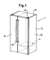
Figure 1 shows an explementary perspective view of a refrigerator according to a preferred embodiment of the present invention; -
Figure 2 shows an explementary perspective view of a part of the refrigerator according to the preferred embodiment of the present invention; -
Figure 3 shows an explementary perspective view of a partition element according to a preferred embodiment of the present invention; -
Figure 4 shows an explementary exploded perspective view of the partition element according to a preferred embodiment of the present invention; and -
Figure 5 shows an explementary section view of the partition element according to a preferred embodiment of the present invention. - In the followed description of preferred embodiments, the same or similar features are referred by the same reference numerals.
- Please refer to attached figures; especially refer to
figures 1 and2 at first. A refrigerator 1 comprises arefrigerator body 15 and two side-by-side combination doors 23 which are connected to therefrigerator body 15. Each of thedoors 23 is pivotally connected at a corresponding side of therefrigerator body 15 by means of one ormore hinges 24, and can be rotated around a rotation shaft parallel with a longitudinal axis. - The
refrigerator body 15 comprises left andright side walls 26, arear wall 30 connecting between the left andright side walls 26, atop wall 28, and abottom wall 29. Therefrigerator body 15 further comprises apartition wall 27 which is located between the left andright side walls 26 and which is substantially parallel with the left andright side walls 26. Thepartition wall 27 is connected with thetop wall 28 and thebottom wall 29 respectively. The left andright side walls 26, therear wall 30, thetop wall 28, thebottom wall 29 and thepartition wall 27 are each comprised of a foam insulation layer (not shown) which is formed by foaming of an insulation foaming material. - By use of the
side walls 26, therear wall 30, thetop wall 28, thebottom wall 29 and thepartition wall 27, therefrigerator body 15 defines afreezing compartment 22 and a refrigeratingcompartment 6 which are arranged side by side. Thefreezing compartment 22 and the refrigeratingcompartment 6 are respectively opened at their front ends, and are closed by thecorresponding doors 23. Thedoor 23 is provided with a foam insulation layer therein, which foam insulation layer is formed by integral foaming of thermal insulation foams. Usually, thedoors 23 are closed to prevent cool air from leaving out of thefreezing compartment 22 and the refrigeratingcompartment 6. If necessary, the user can open the corresponding one of thedoors 23 to for example remove food stuff from thefreezing compartment 22 or from the refrigeratingcompartment 6. The user can usehandles 25 to open and close thedoors 23. - The refrigerating
compartment 6 comprises a partition element 4 which is removably mounded in the refrigerating compartment. The partition element 4 extends in a horizontal direction. The partition element 4 is at its two sides fixed on thepartition wall 27 and thecorresponding side wall 26 in an insertable manner. By means of the partition element 4, therefrigerating compartment 6 is divided into afirst storage space 2 and a second storage space 3 which are independent of each other. The partition element 4 is provided to prevent air from flowing between thefirst storage space 2 and the second storage space 3 and to thermally isolate the twostorage spaces 2 and 3. Therefore, storage parameters such as temperature and/or humidity of thefirst storage space 2 and the second storage space 3 can be independently controlled. In this embodiment, thefirst storage space 2 is located above the second storage space 3. - Preferably, the refrigerator 1 comprises measuring means for respectively measuring the parameters (such as temperature and/or humidity and so on) of the
first storage space 2 and of the second storage 3. Based on the measured parameters, a control unit of the refrigerator 1 can control thefirst storage space 2 and the second storage space 3 respectively. In this embodiment, thefirst storage space 2 is used as a commonly-used refrigerating chamber, and the second storage 3 is used as a temperature controllable chamber, whose temperature can be adjusted in a large range (such as from -10°C to 14°C). - In this embodiment, the
partition wall 27 is provided with a fluid path 11 at the location of the second storage space 3, which fluid path is adapted for fluidly communicating the freezingcompartment 22 with the second storage space 3. Preferably, the fluid path 11 can be opened or closed by the control unit of the refrigerator 1, which is dependent on whether the second storage space 3 requires cool air introduced from the freezingcompartment 22 or not. The opening and closing of the fluid path 11 can be carried out by a leaf blade which is located in the fluid path 11 and which is associated with the control unit. Preferably, a fan is provided in the fluid path 11 to suck cool air from the freezingcompartment 22 as the fluid path 11 is opened such that the temperature of the second storage space 3 is lowered. In an alternative embodiment, the refrigerator 1 can be provided with an individual refrigeration system adapted for the second storage space 3. - As shown in
figures 3 ,4 and 5 , the partition element 4 comprises a hollow glass assembly 7 which is used to prevent the heat exchanging between thefirst storage space 2 and the second storage space 3. The hollow glass assembly 7 is in a flat, rectangular shape and extends in a horizontal direction. - The hollow glass assembly 7 comprises a first glass plate 8 and a
second glass plate 9 located below the first glass plate 8. The distance between the first glass plate 8 and thesecond glass plate 9 can be defined by a separatingdevice 21 located between the first glass plate 8 and thesecond glass plate 9. A hermetically enclosed, thermally insulated space 5 is formed between the first glass plate 8 and thesecond glass plate 9 so that the thermoresistance between thefirst storage space 2 and the second storage space 3 is greatly reduced. The thermally insulated space 5 is filled with inert gas such as argon or krypton. This can enhance the thermal insulation performance of the hollow glass assembly 7 and can prevent moist/condensation/dew from being generated in the hollow glass assembly 7. The hollow glass assembly 7 preferably comprises a sealing device (not shown) provided along the separating device so as to prevent leakage of inert gas and to prevent air from entering into the thermally insulated space 5. - The partition element 4 comprises a
frame 30 provided along the edge of the hollow glass assembly 7. Theframe 30 has anopening 31, the shape of which corresponds with that of the hollow glass assembly 7 but the size of the opening is slightly smaller than that of the hollow glass assembly. Therefore, an upper surface of the first glass plate 8 is exposed in thefirst storage space 2 so as to form a support face for placing item to be cooled thereon for example. - The partition element 4 comprises stop means 32 to prevent the partition element 4 from being forwardly drawn out. In this embodiment, the stop means 32 is embodied as a projection extending downwards from a side of the
frame 30. Thepartition wall 27 and/or the associatedside wall 26 are/is provided with a stop groove (not shown) for receiving the stop means. When the projection is inserted in the stop groove, the horizontal movement of the partition element 4 is limited by the stop groove such that the partition element 4 can be reliably secured in the refrigerator 1 to isolate thefirst storage space 2 from the second storage space 3. In an alternative embodiment, a stop groove can be provided on the partition element 4 and a projection can be provided on thepartition wall 27 and/or theside wall 26 such that the projection can be inserted into the stop groove to implement the securing of the partition element 4. - The partition element 4 comprises a
bottom plate 17 located below the hollow glass assembly 7. Thebottom plate 17 is substantially parallel with thesecond glass plate 9 and is connected to theframe 30 by means of a mountingframe 33 extending upwards from an edge of the bottom plate. Thebottom plate 17 is provided at an interval from thesecond glass plate 19 such that apassage 12 is formed to enable air in the second storage space 3 to leave out of the second storage space 3. - The hollow glass assembly 7 has a length in a front-to-back direction smaller than the depth of the second storage space 3. Therefore, the partition element 4 has an
insulation strip 14 which is provided between a rear end of the hollow glass assembly 7 and a rear surface of the second storage space 3. In this embodiment, theinsulation strip 14 is made of EPS material. - Gas in the second storage space 3 flows into the
passage 12 via a plurality ofinlets 13 formed on thebottom plate 17. Thebottom plate 17 comprises afirst region 18 and asecond region 19, thefirst region 18 being far away from thepartition wall 27 which is provided with the fluid path 11 (which serves as a cooling source for the second storage space 3), and thesecond region 19 being adjacent to thepartition wall 27. Thefirst region 18 and thesecond region 19 are substantially divided by a centerline in a front-to-back direction in thebottom plate 17. In this embodiment, theinlets 13 are mainly provided in thefirst region 18 and thesecond region 19 is free of theinlets 13 such that cool air from the freezingcompartment 22 can be uniformly distributed in the second storage space 3. Each of theinlets 13 is elongate in shape, and theinlets 13 are arranged on thefirst region 18 in a two-row arrangement. - An
outlet 16 of thepassage 12 is oriented toward the rear of the partition element 4 such that theinlets 13 and theoutlet 16 are respectively oriented in planes which are substantially vertical with respect to each other. In this embodiment, by means of an appropriate pipeline (not shown), theoutlet 16 is preferably connected to a chamber for accommodating an evaporator (not shown) for the freezingcompartment 22. Theoutlet 16 is provided at a position corresponding to thesecond region 19 of the bottom 17 so that the flowing path through which air derived from theinlets 13 flows in thepassage 12 can be enlarged. - Preferably, the partition element 4 comprises a
separator sheet 34 provided along one side of theoutlet 16 which is adjacent to thefirst region 18. As shown infigure 5 , theseparator sheet 34 extends into thepassage 12 such that air entering from theinlets 13 arranged adjacent to theoutlet 16 is prevented from flowing out of theoutlet 16 in a very short flowing path. - As shown in
figure 5 , the partition element 4 comprises afilter element 20 for adjusting at least one storage parameter of the second storage space 3. In this embodiment, thefilter element 20 comprises a filtration fabric for filtrating water so as to maintain the humidity of the second storage space 3. In this embodiment, theinlets 13 are covered by thefilter element 20. - The partition element 4 comprises a holding
plate 35 for securing the filtration fabric on the partition element 4. The holdingplate 35 is secured onto thebottom plate 17 and has a shape corresponding with that of thefirst region 18. The holdingplate 35 comprises a plurality of through-holes associated with theinlets 13. - Although the hollow glass assembly 7 is comprised of only two glass plates in the above-mentioned embodiment, it should be understood that in an alternative embodiment, the hollow glass assembly 7 can be comprised of more than two glass plates such as three glass plates.
Claims (12)
- A refrigerator (1) comprising:a first storage space (2);a second storage space (3), at least one storage parameter of which is controlled independent of the first storage space (2); anda partition element (4), which isolates the first storage space (2) from the second storage space (3) ;characterized in that, the partition element (4) comprises a thermally insulated space (5) which is hermetically enclosed and which is filled with inert gas.
- The refrigerator (1) according to claim 1, characterized in that, the partition element (4) is removably mounted in the refrigerator (1).
- The refrigerator (1) according to claim 1 or 2, characterized in that, the partition element (4) is fixed to side walls of the storage space (2) in an insertable manner.
- The refrigerator (1) according to any one of the previous claims, characterized in that, the thermally insulated space (5) is formed by a hollow glass assembly (7), which is comprised of at least two glass plates (8, 9).
- The refrigerator (1) according to claim 4, characterized in that, the hollow refrigerator (7) comprises a first glass plate (8) and a second glass plate (9) located below the first glass plate (8), and an upper surface of the first glass plate (8) is at least partially exposed in the first storage space (2) so as to form a support face for supporting an item to be cooled thereon.
- The refrigerator (1) according to any one of the previous claims, characterized in that, further comprises a freezing compartment (10) isolated from the first storage space (2) and a fluid path (11) enabling cool air to enter the second storage space (3) from the freezing compartment (10).
- The refrigerator (1) according to any one of the previous claims, characterized in that, the partition element (4) comprises a passage (12) fluidly communicating with the second storage space (3) to allow gas to leave out of or to enter into the second storage space (3) via the passage (12).
- The refrigerator (1) according to claim 7, characterized in that, the partition element (4) further comprises a bottom plate (17) which is located below the second glass plate (9), and the bottom plate (17) is provided at an interval from the second glass plate (9) so that the passage (12) is formed.
- The refrigerator (1) according to claim 7 or 8, characterized in that, the passage (12) comprises an inlet (13) fluidly communicating with the second storage space (3), which inlet (13) is far away from a cooling source for the storage space (3).
- The refrigerator (1) according to claim 9, characterized in that, the inlet (13) is formed on a lower surface of the partition element (4).
- The refrigerator (1) according to claim 8, characterized in that, the passage (12) comprises a plurality of inlets (13) fluidly communicating with the second storage space (3), the bottom plate (17) comprises a first region (18) in which the inlets (13) are arranged and a second region (19) which is free of the inlets (13), and the first region (18) is farther away from the second storage space (3) than the second region (19).
- The refrigerator (1) according to any one of the previous claims, characterized in that, the partition element (4) further comprises a filter element (20) for adjusting the at least one parameter of the second storage space (3).
Applications Claiming Priority (2)
| Application Number | Priority Date | Filing Date | Title |
|---|---|---|---|
| CN 200810244395 CN101749911B (en) | 2008-11-28 | 2008-11-28 | Refrigerator |
| PCT/IB2009/055333 WO2010061340A2 (en) | 2008-11-28 | 2009-11-25 | Refrigerator |
Publications (1)
| Publication Number | Publication Date |
|---|---|
| EP2372278A2 true EP2372278A2 (en) | 2011-10-05 |
Family
ID=42226178
Family Applications (1)
| Application Number | Title | Priority Date | Filing Date |
|---|---|---|---|
| EP09810793A Withdrawn EP2372278A2 (en) | 2008-11-28 | 2009-11-25 | Refrigerator |
Country Status (4)
| Country | Link |
|---|---|
| EP (1) | EP2372278A2 (en) |
| CN (1) | CN101749911B (en) |
| RU (1) | RU2512324C2 (en) |
| WO (1) | WO2010061340A2 (en) |
Families Citing this family (1)
| Publication number | Priority date | Publication date | Assignee | Title |
|---|---|---|---|---|
| CN103174706B (en) * | 2011-12-22 | 2017-03-15 | 博西华电器(江苏)有限公司 | Household electrical appliance are combined |
Family Cites Families (15)
| Publication number | Priority date | Publication date | Assignee | Title |
|---|---|---|---|---|
| US3232072A (en) * | 1965-01-08 | 1966-02-01 | Louis F Barroero | Shelf structure for refrigeration |
| SE7909844L (en) * | 1979-11-29 | 1981-05-30 | Electrolux Ab | SET AND DEVICE FOR KEEPING A FROZEN FREEZE |
| GB8508732D0 (en) * | 1985-04-03 | 1985-05-09 | Ti Domestic Appliances Ltd | Refrigerating systems |
| US5362145A (en) * | 1991-03-07 | 1994-11-08 | Donnelly Corporation | Molded refrigerator shelf |
| US5273354A (en) * | 1991-03-07 | 1993-12-28 | Donnelly Corporation | Molded refrigerator shelf and support bracket |
| CN2351432Y (en) * | 1997-09-18 | 1999-12-01 | 上海华鹰技术玻璃有限公司 | High heat insulation and sound-proofing hollow glass |
| DE10208056A1 (en) * | 2002-02-25 | 2003-09-04 | Bsh Bosch Siemens Hausgeraete | Edge finishing part for a glass plate |
| ITMI20021179A1 (en) * | 2002-05-31 | 2003-12-01 | Whirlpool Co | SUPPORT ELEMENT FOR FOODS SUITABLE FOR REMOVABLE INTRODUCTION IN A REFRIGERATOR COMPARTMENT WITH DIFFERENTIATED TEMPERATURE AREAS |
| KR100889821B1 (en) * | 2003-01-27 | 2009-03-20 | 삼성전자주식회사 | Refrigerator with temperature control chamber |
| US6779357B1 (en) * | 2003-02-07 | 2004-08-24 | Viking Range Corporation | Mullion shelf assembly |
| US7021334B1 (en) | 2003-09-29 | 2006-04-04 | Bld Products, Ltd. | Fluid coupling |
| CN2722153Y (en) * | 2004-08-12 | 2005-08-31 | 白尚富 | Built-in shelf vacuum thermal insulative board of refrigerator |
| CN100498159C (en) * | 2004-09-20 | 2009-06-10 | 乐金电子(天津)电器有限公司 | Partition regulator for refrigerator |
| ITVA20040020U1 (en) * | 2004-12-07 | 2005-03-07 | Whirlpool Co | NO-FROST REFRIGERATOR |
| CN101126585A (en) * | 2006-08-17 | 2008-02-20 | 泰州乐金电子冷机有限公司 | Refrigerator with closed storage room |
-
2008
- 2008-11-28 CN CN 200810244395 patent/CN101749911B/en not_active Expired - Fee Related
-
2009
- 2009-11-25 EP EP09810793A patent/EP2372278A2/en not_active Withdrawn
- 2009-11-25 WO PCT/IB2009/055333 patent/WO2010061340A2/en not_active Ceased
- 2009-11-25 RU RU2011123158/13A patent/RU2512324C2/en not_active IP Right Cessation
Non-Patent Citations (2)
| Title |
|---|
| None * |
| See also references of WO2010061340A2 * |
Also Published As
| Publication number | Publication date |
|---|---|
| WO2010061340A3 (en) | 2012-04-05 |
| RU2011123158A (en) | 2013-01-10 |
| RU2512324C2 (en) | 2014-04-10 |
| WO2010061340A2 (en) | 2010-06-03 |
| CN101749911A (en) | 2010-06-23 |
| CN101749911B (en) | 2012-11-07 |
Similar Documents
| Publication | Publication Date | Title |
|---|---|---|
| CN102914119B (en) | Refrigerating appliance | |
| KR20140121536A (en) | Refrigerator | |
| ITFI20110018A1 (en) | REFRIGERATOR APPARATUS. | |
| US10718559B2 (en) | Air filter bracket | |
| JP5138356B2 (en) | Open showcase | |
| JP6000919B2 (en) | refrigerator | |
| CN103629877B (en) | Refrigerator | |
| WO2012140854A1 (en) | Refrigerator | |
| CN110140018B (en) | Freezer and method for retrofitting a freezer | |
| WO2012076460A2 (en) | Refrigerator | |
| RU2512324C2 (en) | Refrigerating unit | |
| CN102914113B (en) | refrigerator | |
| JP2022032329A (en) | refrigerator | |
| WO2022034698A1 (en) | Refrigerator | |
| JP5271134B2 (en) | Freezer refrigerator | |
| JP6788892B2 (en) | refrigerator | |
| WO2012076451A2 (en) | Refrigeration appliance | |
| CN101893361B (en) | Refrigerator | |
| JP2010230217A (en) | Freezer refrigerator | |
| CN110100138B (en) | Freezer and method for retrofitting a freezer | |
| CN205641736U (en) | Refrigerating equipment | |
| JP3227961U (en) | Refrigerator and humidifier for refrigerator | |
| JP5431763B2 (en) | Freezer refrigerator | |
| EP1544558B1 (en) | Chest Freezer | |
| JP2005083665A (en) | refrigerator |
Legal Events
| Date | Code | Title | Description |
|---|---|---|---|
| PUAI | Public reference made under article 153(3) epc to a published international application that has entered the european phase |
Free format text: ORIGINAL CODE: 0009012 |
|
| AK | Designated contracting states |
Kind code of ref document: A2 Designated state(s): AT BE BG CH CY CZ DE DK EE ES FI FR GB GR HR HU IE IS IT LI LT LU LV MC MK MT NL NO PL PT RO SE SI SK SM TR |
|
| AX | Request for extension of the european patent |
Extension state: AL BA RS |
|
| DAX | Request for extension of the european patent (deleted) | ||
| R17D | Deferred search report published (corrected) |
Effective date: 20120405 |
|
| 17P | Request for examination filed |
Effective date: 20121005 |
|
| RBV | Designated contracting states (corrected) |
Designated state(s): AT BE BG CH CY CZ DE DK EE ES FI FR GB GR HR HU IE IS IT LI LT LU LV MC MK MT NL NO PL PT RO SE SI SK SM TR |
|
| RAP1 | Party data changed (applicant data changed or rights of an application transferred) |
Owner name: BSH HAUSGERAETE GMBH |
|
| 17Q | First examination report despatched |
Effective date: 20180220 |
|
| GRAP | Despatch of communication of intention to grant a patent |
Free format text: ORIGINAL CODE: EPIDOSNIGR1 |
|
| INTG | Intention to grant announced |
Effective date: 20181218 |
|
| STAA | Information on the status of an ep patent application or granted ep patent |
Free format text: STATUS: THE APPLICATION IS DEEMED TO BE WITHDRAWN |
|
| 18D | Application deemed to be withdrawn |
Effective date: 20190430 |