EP2372106A1 - Turbogenerator - Google Patents
Turbogenerator Download PDFInfo
- Publication number
- EP2372106A1 EP2372106A1 EP11002470A EP11002470A EP2372106A1 EP 2372106 A1 EP2372106 A1 EP 2372106A1 EP 11002470 A EP11002470 A EP 11002470A EP 11002470 A EP11002470 A EP 11002470A EP 2372106 A1 EP2372106 A1 EP 2372106A1
- Authority
- EP
- European Patent Office
- Prior art keywords
- rotor
- alternating
- current
- generator
- permanent magnet
- Prior art date
- Legal status (The legal status is an assumption and is not a legal conclusion. Google has not performed a legal analysis and makes no representation as to the accuracy of the status listed.)
- Granted
Links
- 238000004804 winding Methods 0.000 claims abstract description 22
- 230000005284 excitation Effects 0.000 claims abstract description 19
- 230000008878 coupling Effects 0.000 claims description 13
- 238000010168 coupling process Methods 0.000 claims description 13
- 238000005859 coupling reaction Methods 0.000 claims description 13
- 230000004323 axial length Effects 0.000 claims description 3
- 230000004907 flux Effects 0.000 description 5
- 230000005347 demagnetization Effects 0.000 description 3
- 230000000052 comparative effect Effects 0.000 description 2
- 238000010586 diagram Methods 0.000 description 2
- 230000002427 irreversible effect Effects 0.000 description 2
- 230000009467 reduction Effects 0.000 description 2
- 230000009471 action Effects 0.000 description 1
- 230000001419 dependent effect Effects 0.000 description 1
- 230000005674 electromagnetic induction Effects 0.000 description 1
- 238000009434 installation Methods 0.000 description 1
- 230000004048 modification Effects 0.000 description 1
- 238000012986 modification Methods 0.000 description 1
- 229910001172 neodymium magnet Inorganic materials 0.000 description 1
- NJPPVKZQTLUDBO-UHFFFAOYSA-N novaluron Chemical compound C1=C(Cl)C(OC(F)(F)C(OC(F)(F)F)F)=CC=C1NC(=O)NC(=O)C1=C(F)C=CC=C1F NJPPVKZQTLUDBO-UHFFFAOYSA-N 0.000 description 1
- 229910052761 rare earth metal Inorganic materials 0.000 description 1
- 150000002910 rare earth metals Chemical class 0.000 description 1
Images


Classifications
-
- F—MECHANICAL ENGINEERING; LIGHTING; HEATING; WEAPONS; BLASTING
- F02—COMBUSTION ENGINES; HOT-GAS OR COMBUSTION-PRODUCT ENGINE PLANTS
- F02C—GAS-TURBINE PLANTS; AIR INTAKES FOR JET-PROPULSION PLANTS; CONTROLLING FUEL SUPPLY IN AIR-BREATHING JET-PROPULSION PLANTS
- F02C7/00—Features, components parts, details or accessories, not provided for in, or of interest apart form groups F02C1/00 - F02C6/00; Air intakes for jet-propulsion plants
- F02C7/26—Starting; Ignition
- F02C7/268—Starting drives for the rotor, acting directly on the rotor of the gas turbine to be started
-
- F—MECHANICAL ENGINEERING; LIGHTING; HEATING; WEAPONS; BLASTING
- F01—MACHINES OR ENGINES IN GENERAL; ENGINE PLANTS IN GENERAL; STEAM ENGINES
- F01D—NON-POSITIVE DISPLACEMENT MACHINES OR ENGINES, e.g. STEAM TURBINES
- F01D15/00—Adaptations of machines or engines for special use; Combinations of engines with devices driven thereby
- F01D15/10—Adaptations for driving, or combinations with, electric generators
Definitions
- the present invention relates to a turbogenerator including a brushless exciter.
- the above-mentioned known structure is disadvantageous in that a rotating shaft is required to have an overhang for mounting of the sub-exciter and the shaft length is increased correspondingly.
- the overhang may become the cause of generating shaft vibrations.
- the present invention provides a turbogenerator according to the independent claims.
- the dependent claims relate to preferred embodiments.
- a turbogenerator can comprise a rotor over which a field winding is disposed, a generator for alternating-current excitation including a permanent magnet disposed over the rotor and generating a current with a magnetic field produced by the permanent magnet, and/or an exciter for supplying a current to the field winding of the rotor based on the current generated by a sub-exciter, wherein the generator for alternating-current excitation may be disposed on the side nearer to the turbine than a stator.
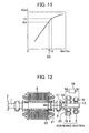
- Fig. 12 illustrates, as a comparative example, one example of a known turbogenerator including a brushless exciter.
- the turbogenerator has an alternating-current (AC) exciter 4 and a sub-exciter 5 both mounted in an end region of a rotor of the turbogenerator.
- the sub-exciter 5 has a permanent magnet 13 as a rotor magnet pole, and the permanent magnet 13 forms a magnetic field perpendicular to an armature winding 8.
- an AC current I a1 is induced in the armature winding 8 based on the electromagnetic induction action.
- An auto voltage regulator 16 having the rectifying function detects a generator voltage, converts the AC current I a1 to a DC current I d1 , and supplies the DC current I d1 to a field winding 18 of the AC exciter 4.
- An armature winding 19 of the AC exciter 4 is mounted over a rotor 20 of the AC exciter, and an AC current I a2 is induced in the armature winding 19 with the rotation of the rotating shaft 1.
- the induced AC current I a2 is converted to a DC current through a rotating rectifier 17 and is supplied to a field winding 21 of the turbogenerator.
- FIG. 13 shows one example of a circuit diagram showing a manner of brushless excitation in the comparative example.
- Fig. 1 illustrates a first embodiment of the present invention.
- a rotating shaft 1 is connected to a turbine through a coupling 3.
- a sub-exciter 5 is mounted over the rotating shaft 1 on the side nearer to the turbine than a stator 2.
- An alternating-current (AC) exciter 4 is mounted over the rotating shaft 1 in its end region on the side opposite to the turbine.
- AC alternating-current
- Fig. 2 illustrates a second embodiment of the present invention.
- the sub-exciter 5 is mounted over the rotating shaft 1 between a turbine-side bearing 6 for supporting the rotating shaft 1 and the coupling 3. With such an arrangement, the length of an overhang required for mounting of the sub-exciter can be reduced.
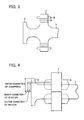
- Fig. 3 illustrates a third embodiment of the present invention.
- a turbogenerator having a coupling 3 that is co-cut from a rotating shaft 1 when a sub-exciter having a ring-shaped rotor 9 is mounted over the rotating shaft on the side near the turbine by shrink fitting, an inner diameter of the rotor 9 of the sub-exciter requires to be larger than an outer diameter of the coupling 3.
- a pedestal portion having a larger diameter than the coupling 3 is cut from the rotating shaft so that the ring-shaped rotor can be mounted in place by shrink fitting.
- Figs. 4 and 5 illustrate a fourth embodiment of the present invention. Because the rotor of the sub-exciter is mounted over the rotating shaft of the turbogenerator rotating at a high speed, an enlarged outer diameter increases a centrifugal force.
- a stator 7 of the sub-exciter 5, including the armature winding 8, is of a structure capable of being split in the circumferential direction and a magnetic pole 23 is directly mounted over the rotating shaft.
- the sub-exciter can be mounted even with the stator 7 having an inner diameter smaller than the outer diameter of the coupling 3.
- Fig. 4 is a view looking in the radial direction
- Fig. 5 is a view looking in the axial direction from the turbine side.
- Fig. 6 illustrates a fifth embodiment of the present invention.
- Fig. 6 shows a half of the divided stator in which armature windings 8a and 8b of the sub-exciter are wound over one of teeth 10 (or in halves of slots on both sides of each tooth) formed in a stator core 9 of the sub-exciter.
- Other armature windings accommodated in other slots are also wound in a similarly concentrated manner.
- the stator 7 of the sub-exciter can be split in the circumferential direction at any desired one of slots 11.
- Figs. 7 and 8 illustrate a sixth embodiment of the present invention.
- Fig. 7 is an axial sectional view of a magnetic pole of the sub-exciter provided in the turbogenerator of the present invention.
- the permanent magnet 13 is mounted between the rotating shaft 1 and a pole shoe 12 and is covered with a magnet cover 14 made of a nonmagnetic material so that the permanent magnet 13 is prevented from being dislodged and flying outward.
- the magnet cover 14 should be nonmagnetic to prevent establishment of a short-circuiting path of magnetic flux from the pole shoe 12 to the rotating shaft 1.
- a minimum air gap Ga (mm) between the stator 7 and the rotor of the sub-exciter is set not smaller than 5 mm so as to prevent generation of heat in the surface of the pole shoe 12 due to an eddy current losses.
- a distance Gp (mm) between the pole shoe 12 and the rotating shaft 1 and a thickness Gm (mm) of the permanent magnet 13 satisfy the relationships of 0.9 ⁇ Gp/Ga and 0.9 ⁇ Gm/Ga. With such settings, the magnetic flux can be prevented from leaking from the pole shoe 12 to the rotating shaft 1.
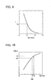
- Fig. 9 shows an analysis result representing the relationship between the air gap Ga and a permanent magnet temperature T.
- the irreversible thermal demagnetization temperature is about from 90°C to 220°C. Therefore, the permanent magnet can be used without causing thermal demagnetization by setting the air gap Ga to be not smaller than 5 mm.
- Fig. 10 shows an analysis result representing the relationship between Gp/Ga and an induced voltage V of the sub-exciter.
- Gp/Ga when Gp/Ga is smaller than 0.9, the induced voltage V is reduced due to a leakage of magnetic flux from the pole shoe to the rotating shaft.
- Gp/Ga By setting Gp/Ga to be not smaller than 0.9, a reduction of the induced voltage V can be avoided.
- Fig. 11 shows an analysis result representing the relationship between Gm/Ga and an induced voltage V of the sub-exciter.
- Fig. 11 by setting the magnet thickness so as to satisfy the relationship of 0.9 ⁇ Gm/Ga, a reduction of the induced voltage V can be avoided without forming a magnetic gap around the permanent magnet.
- Fig. 8 is a sectional view of the magnetic pole of the sub-exciter provided in the turbogenerator of the present invention, the view being taken along the radial direction.
- the pole shoe 12 has a longer axial length than the permanent magnet 13, and bolt holes are formed in portions of the pole shoe 12 axially extending with respect to the permanent magnet 13.
- the pole shoe 12 is fixed in place by fastening nonmagnetic bolts 15 into the bolt holes.
- the pole shoe 12 can be mounted in place by the bolts with no need of forming holes in the permanent magnet without impeding main magnetic flux in the pole shoe 12.
- nonmagnetic bolts it is possible to prevent establishment of a short-circuiting path of magnetic flux from the pole shoe 12 to the rotating shaft 1.
Abstract
a permanent magnet (13) disposed on said rotor; a generator for alternating-current excitation generating a current with a magnetic field produced by said permanent magnet (13) ; an exciter (4) for supplying a current to the field winding (21) of said rotor based on the current generated by said generator for alternating-current excitation; and a turbine for producing motive power to rotate said rotor. The permanent magnet (13) of said generator for alternating-current excitation is disposed between a pole shoe (12) and a rotating shaft (1) of said rotor. (
Description
- The present invention relates to a turbogenerator including a brushless exciter.
- In a known structure of a turbogenerator including a brushless exciter, an alternating-current (AC) exciter and a sub-exciter are mounted in an end region on the side opposite to a turbine, as disclosed in
Patent Document 1;JP-A-2003-515308 - The above-mentioned known structure is disadvantageous in that a rotating shaft is required to have an overhang for mounting of the sub-exciter and the shaft length is increased correspondingly. The overhang may become the cause of generating shaft vibrations.
- To solve the aforesaid object, the present invention provides a turbogenerator according to the independent claims. The dependent claims relate to preferred embodiments.
- According to one aspect of the present invention, a turbogenerator can comprise a rotor over which a field winding is disposed, a generator for alternating-current excitation including a permanent magnet disposed over the rotor and generating a current with a magnetic field produced by the permanent magnet, and/or an exciter for supplying a current to the field winding of the rotor based on the current generated by a sub-exciter, wherein the generator for alternating-current excitation may be disposed on the side nearer to the turbine than a stator.
- With the present invention, it is possible to shorten the length of an overhang provided in an end region of a turbogenerator, to reduce the size of the turbogenerator, and to suppress shaft vibrations.
-
-
Fig. 1 illustrates a first embodiment of the present invention; -
Fig. 2 illustrates a second embodiment of the present invention; -
Fig. 3 illustrates a third embodiment of the present invention; -
Fig. 4 illustrates a fourth embodiment of the present invention; -
Fig. 5 is an end view looking components inFig. 4 in the axial direction from the turbine side; -
Fig. 6 illustrates a fifth embodiment of the present invention; -
Fig. 7 illustrates a sixth embodiment of the present invention; -
Fig. 8 is a sectional view of components inFig. 7 taken along the radial direction; -
Fig. 9 is a graph showing the relationship between an air gap and a permanent magnet temperature; -
Fig. 10 is a graph showing the relationship between a ratio of the distance from a pole shoe to a rotor shaft to an air gap and an induced voltage; -
Fig. 11 is a graph showing the relationship between a ratio of a magnet thickness to the air gap and an induced voltage; -
Fig. 12 illustrates a known turbogenerator including a brushless exciter; and -
Fig. 13 is a circuit diagram showing a manner of brushless excitation. - For easier understanding of the advantages of the present invention,
Fig. 12 illustrates, as a comparative example, one example of a known turbogenerator including a brushless exciter. The turbogenerator has an alternating-current (AC) exciter 4 and asub-exciter 5 both mounted in an end region of a rotor of the turbogenerator. Thesub-exciter 5 has apermanent magnet 13 as a rotor magnet pole, and thepermanent magnet 13 forms a magnetic field perpendicular to an armature winding 8. When the magnetic field is rotated with the rotation of arotating shaft 1, an AC current Ia1 is induced in the armature winding 8 based on the electromagnetic induction action. Anauto voltage regulator 16 having the rectifying function detects a generator voltage, converts the AC current Ia1 to a DC current Id1, and supplies the DC current Id1 to a field winding 18 of the AC exciter 4. An armature winding 19 of theAC exciter 4 is mounted over arotor 20 of the AC exciter, and an AC current Ia2 is induced in the armature winding 19 with the rotation of the rotatingshaft 1. The induced AC current Ia2 is converted to a DC current through a rotatingrectifier 17 and is supplied to a field winding 21 of the turbogenerator. Then, with the rotation of the rotatingshaft 1, an AC current is induced in an armature winding 22 of the turbogenerator, whereby electric power can be supplied to the outside.Fig. 13 shows one example of a circuit diagram showing a manner of brushless excitation in the comparative example. - Embodiments of the present invention will be described below with reference to the drawings.
-
Fig. 1 illustrates a first embodiment of the present invention. A rotatingshaft 1 is connected to a turbine through acoupling 3. Asub-exciter 5 is mounted over the rotatingshaft 1 on the side nearer to the turbine than astator 2. An alternating-current (AC)exciter 4 is mounted over the rotatingshaft 1 in its end region on the side opposite to the turbine. - By thus mounting the sub-exciter on the side near the turbine, the length of an overhang at the shaft end can be reduced in amount that has been required for installation of the permanent magnet in the related art.
-
Fig. 2 illustrates a second embodiment of the present invention. Thesub-exciter 5 is mounted over the rotatingshaft 1 between a turbine-side bearing 6 for supporting the rotatingshaft 1 and thecoupling 3. With such an arrangement, the length of an overhang required for mounting of the sub-exciter can be reduced. -
Fig. 3 illustrates a third embodiment of the present invention. In a turbogenerator having acoupling 3 that is co-cut from a rotatingshaft 1, when a sub-exciter having a ring-shaped rotor 9 is mounted over the rotating shaft on the side near the turbine by shrink fitting, an inner diameter of therotor 9 of the sub-exciter requires to be larger than an outer diameter of thecoupling 3. To meet such a requirement, as shown inFig. 3 , a pedestal portion having a larger diameter than thecoupling 3 is cut from the rotating shaft so that the ring-shaped rotor can be mounted in place by shrink fitting. -
Figs. 4 and5 illustrate a fourth embodiment of the present invention. Because the rotor of the sub-exciter is mounted over the rotating shaft of the turbogenerator rotating at a high speed, an enlarged outer diameter increases a centrifugal force. - To avoid such a drawback, as shown in
Figs. 4 and5 , astator 7 of thesub-exciter 5, including the armature winding 8, is of a structure capable of being split in the circumferential direction and amagnetic pole 23 is directly mounted over the rotating shaft. With such an arrangement, the sub-exciter can be mounted even with thestator 7 having an inner diameter smaller than the outer diameter of thecoupling 3.Fig. 4 is a view looking in the radial direction, andFig. 5 is a view looking in the axial direction from the turbine side. -
Fig. 6 illustrates a fifth embodiment of the present invention.Fig. 6 shows a half of the divided stator in whicharmature windings stator core 9 of the sub-exciter. Other armature windings accommodated in other slots are also wound in a similarly concentrated manner. With such an arrangement, thestator 7 of the sub-exciter can be split in the circumferential direction at any desired one ofslots 11. -
Figs. 7 and 8 illustrate a sixth embodiment of the present invention.Fig. 7 is an axial sectional view of a magnetic pole of the sub-exciter provided in the turbogenerator of the present invention. Thepermanent magnet 13 is mounted between therotating shaft 1 and apole shoe 12 and is covered with amagnet cover 14 made of a nonmagnetic material so that thepermanent magnet 13 is prevented from being dislodged and flying outward. The magnet cover 14 should be nonmagnetic to prevent establishment of a short-circuiting path of magnetic flux from thepole shoe 12 to therotating shaft 1. - In
Fig. 7 , a minimum air gap Ga (mm) between thestator 7 and the rotor of the sub-exciter is set not smaller than 5 mm so as to prevent generation of heat in the surface of thepole shoe 12 due to an eddy current losses. Also, a distance Gp (mm) between thepole shoe 12 and therotating shaft 1 and a thickness Gm (mm) of thepermanent magnet 13 satisfy the relationships of 0.9 < Gp/Ga and 0.9 < Gm/Ga. With such settings, the magnetic flux can be prevented from leaking from thepole shoe 12 to therotating shaft 1. -
Fig. 9 shows an analysis result representing the relationship between the air gap Ga and a permanent magnet temperature T. InFig. 9 , To indicates the irreversible thermal demagnetization temperature of a permanent magnet. In the case of a neodymium magnet, for example, the irreversible thermal demagnetization temperature is about from 90°C to 220°C. Therefore, the permanent magnet can be used without causing thermal demagnetization by setting the air gap Ga to be not smaller than 5 mm. -
Fig. 10 shows an analysis result representing the relationship between Gp/Ga and an induced voltage V of the sub-exciter. As will be seen fromFig. 10 , when Gp/Ga is smaller than 0.9, the induced voltage V is reduced due to a leakage of magnetic flux from the pole shoe to the rotating shaft. By setting Gp/Ga to be not smaller than 0.9, a reduction of the induced voltage V can be avoided. Also,Fig. 11 shows an analysis result representing the relationship between Gm/Ga and an induced voltage V of the sub-exciter. As will be seen fromFig. 11 , by setting the magnet thickness so as to satisfy the relationship of 0.9 < Gm/Ga, a reduction of the induced voltage V can be avoided without forming a magnetic gap around the permanent magnet. -
Fig. 8 is a sectional view of the magnetic pole of the sub-exciter provided in the turbogenerator of the present invention, the view being taken along the radial direction. Thepole shoe 12 has a longer axial length than thepermanent magnet 13, and bolt holes are formed in portions of thepole shoe 12 axially extending with respect to thepermanent magnet 13. Thepole shoe 12 is fixed in place by fasteningnonmagnetic bolts 15 into the bolt holes. By forming the bolt fastening holes at positions located in the portions of thepole shoe 12 axially extending with respect to thepermanent magnet 13, thepole shoe 12 can be mounted in place by the bolts with no need of forming holes in the permanent magnet without impeding main magnetic flux in thepole shoe 12. In addition, by using nonmagnetic bolts, it is possible to prevent establishment of a short-circuiting path of magnetic flux from thepole shoe 12 to therotating shaft 1. - Conceivable practical forms of the present invention are as follows:
- (1) A turbogenerator may comprise a rotor over which a field winding is disposed, a coupling co-cut from a rotor shaft, an AC exciter for supplying a DC current to the field winding through a rotary rectifier, and/or a sub-exciter including a permanent magnet as a field generator and supplying a DC current to a field winding of the AC exciter through an auto voltage regulator having the rectifying function. The AC exciter and the sub-exciter may be disposed over the rotor shaft. The rotor is rotated through engagement between a steam turbine or a gas turbine, serving as a prime mover, and the coupling. The sub-exciter may be mounted in a position on the side nearer to the turbine than a stator of the turbogenerator.
- (2) In the turbogenerator of (1), the sub-exciter may be disposed between the coupling and a rotor bearing located on the side nearer to the turbine.
- (3) In the turbogenerator of (1) or (2), a stator of the sub-exciter may be capable of being split in the circumferential direction, and/or the stator of the sub-exciter may have an inner diameter smaller than an outer diameter of the coupling.
- (4) In the turbogenerator of (1) to (3), an armature winding of the sub-exciter may be wound in a lumped manner.
- (5) In the turbogenerator of (1) to (4), the permanent magnet serving as a field generator for the sub-exciter may be a rare earth magnet.
- (6) In the turbogenerator of (1) to (5), the permanent magnet of the sub-exciter may be directly mounted over the rotor shaft of the turbogenerator.
- (7) In the turbogenerator of (1) to (6), the permanent magnet of the sub-exciter may be mounted between a pole shoe and the rotor shaft of the turbogenerator.
- (8) In the turbogenerator of (1) to (7), the permanent magnet of the sub-exciter may be a magnetized permanent magnet.
- (9) In the turbogenerator of (1) to (8), the permanent magnet of the sub-exciter may be covered with a cover made of a nonmagnetic material.
- (10) In the turbogenerator of (1) to (9), the pole shoe of the sub-exciter may be mounted in place by fastening nonmagnetic bolts.
- (11) In the turbogenerator of (1) to (10), the pole shoe of the sub-exciter may have portions extending in excess of an axial length of the permanent magnet, and/or bolt holes may be formed in the extending portions of the pole shoe.
- (12) In the turbogenerator of (1) to (11), a minimum gap between the stator of the sub-exciter and the rotor may not be smaller than 5 mm.
- (13) In the turbogenerator of (1) to (12), assuming that a minimum gap between the stator of the sub-exciter and the rotor is Ga (mm) and a distance between the pole shoe and the rotor shaft is Gp (mm), the relationship of 0.9 < Gp/Ga may be satisfied.
- (14) In the turbogenerator of (1) to (13), assuming that a minimum gap between the stator of the sub-exciter and the rotor is Ga (mm) and a thickness of the permanent magnet is Gm (mm), the relationship of 0.9 < Gm/Ga may be satisfied.
- The above described exemplary embodiments can be combined in any way as a whole or in part in order to build up further embodiments optimized for the respective application. As far as such modifications of the above described embodiments are readily apparent for the skilled person they shall be disclosed implicitly by the above description of
embodiments 1 to 6.
Claims (9)
- A turbogenerator comprising:a rotor over which a field winding (21) is disposed;a permanent magnet (13) disposed on said rotor;a generator for alternating-current excitation generating a current with a magnetic field produced by said permanent magnet (13);an exciter (4) for supplying a current to the field winding (21) of said rotor based on the current generated by said generator for alternating-current excitation; anda turbine for producing motive power to rotate said rotor,wherein the permanent magnet (13) of said generator for alternating-current excitation is disposed between a pole shoe (12) and a rotating shaft (1) of said rotor.
- The turbogenerator according to Claim 1, wherein said pole shoe (12) has portions extending longer than an axial length of said permanent magnet (13), bolt holes are formed in the extending portions of said pole shoe (12), and said pole shoe (12) is fixed to the rotating shaft (1) of said rotor by bolts (15) fastened into said bolt holes.
- The turbogenerator according to Claim 1 or 2, wherein a minimum gap between a stator of said generator for alternating-current excitation and said rotor is not smaller than 5 mm.
- The turbogenerator according to one of Claims 1 to 3, wherein assuming that a minimum gap between a stator of said generator for alternating-current excitation and said rotor is Ga and a thickness of said permanent magnet is Gm, the relationship of 0.9 < Gm/Ga is satisfied.
- The turbogenerator according to one of Claims 1 to 4, wherein a portion of said rotor in which said generator for alternating-current excitation is disposed has an outer diameter larger than an outer diameter of the other portion of said rotor.
- A turbogenerator comprising:a rotor over which a field winding (21) is disposed;a permanent magnet (13) disposed on said rotor;a generator for alternating-current excitation generating a current with a magnetic field produced by said permanent magnet;an exciter (4) for supplying a current to the field winding (21) of said rotor based on the current generated by said generator for alternating-current excitation; anda turbine for producing motive power to rotate said rotor,wherein said generator for alternating-current excitation is disposed on the side nearer to said turbine than a stator.
- The turbogenerator according to Claim 6, wherein said generator for alternating-current excitation is disposed between a coupling (3) and a rotor bearing located on the side nearer to said turbine, said coupling (3) connecting said turbine and said rotor to each other.
- The turbogenerator according to Claim 6 or 7, wherein a stator (7) of said generator for alternating-current excitation is capable of being split in the circumferential direction.
- The turbogenerator according to one of Claims 6 to 8, wherein the stator (7) of said generator for alternating-current excitation has an inner diameter smaller than an outer diameter of said coupling (3).
Applications Claiming Priority (2)
| Application Number | Priority Date | Filing Date | Title |
|---|---|---|---|
| JP2004372481A JP4591075B2 (en) | 2004-12-24 | 2004-12-24 | Turbine generator |
| EP05017866A EP1679427B1 (en) | 2004-12-24 | 2005-08-17 | Turbogenerator |
Related Parent Applications (1)
| Application Number | Title | Priority Date | Filing Date |
|---|---|---|---|
| EP05017866.4 Division | 2005-08-17 |
Publications (2)
| Publication Number | Publication Date |
|---|---|
| EP2372106A1 true EP2372106A1 (en) | 2011-10-05 |
| EP2372106B1 EP2372106B1 (en) | 2012-11-21 |
Family
ID=36215531
Family Applications (2)
| Application Number | Title | Priority Date | Filing Date |
|---|---|---|---|
| EP05017866A Active EP1679427B1 (en) | 2004-12-24 | 2005-08-17 | Turbogenerator |
| EP11002470A Active EP2372106B1 (en) | 2004-12-24 | 2005-08-17 | Turbogenerator |
Family Applications Before (1)
| Application Number | Title | Priority Date | Filing Date |
|---|---|---|---|
| EP05017866A Active EP1679427B1 (en) | 2004-12-24 | 2005-08-17 | Turbogenerator |
Country Status (4)
| Country | Link |
|---|---|
| US (1) | US7732958B2 (en) |
| EP (2) | EP1679427B1 (en) |
| JP (1) | JP4591075B2 (en) |
| CN (2) | CN101170269A (en) |
Families Citing this family (8)
| Publication number | Priority date | Publication date | Assignee | Title |
|---|---|---|---|---|
| EP2528201A1 (en) * | 2011-05-24 | 2012-11-28 | Alstom Technology Ltd | Method for applying a retaining system above a rotor core of an electric machine and rotor assembly |
| WO2013067605A2 (en) * | 2011-11-09 | 2013-05-16 | Banjanovic Nijaz | New system excitation of classical synchronous generators |
| US20130169074A1 (en) * | 2011-12-31 | 2013-07-04 | Sheikh Nayyer Hussain | Synchronous relcutance motor for conducting media |
| EP2704310B1 (en) * | 2012-08-28 | 2019-02-13 | GE Renewable Technologies | Method for operating such an electrical machine |
| US8963510B1 (en) * | 2013-08-23 | 2015-02-24 | Kohler Co. | Acyclic exciter for an alternator |
| KR102069734B1 (en) * | 2016-02-12 | 2020-01-28 | 지멘스 악티엔게젤샤프트 | Gas turbine train with starting motor |
| CN108757351B (en) * | 2018-03-29 | 2020-05-26 | 北京金风科创风电设备有限公司 | Direct-drive wind generating set |
| CN109742898B (en) * | 2018-12-28 | 2020-11-03 | 西安航天泵业有限公司 | Integrated totally-enclosed low-temperature hydraulic power generation device |
Citations (8)
| Publication number | Priority date | Publication date | Assignee | Title |
|---|---|---|---|---|
| US3821633A (en) * | 1971-10-25 | 1974-06-28 | Reyrolle Parsons Ltd | Dynamo electric machines |
| US3863137A (en) * | 1972-08-23 | 1975-01-28 | Hitachi Ltd | Exciting system for alternator |
| GB1523467A (en) * | 1975-11-06 | 1978-08-31 | Plessey Co Ltd | Rotary electric machines |
| US4918343A (en) * | 1988-10-13 | 1990-04-17 | Kohler Co. | Brushless alternator |
| JP2003515308A (en) | 1999-11-24 | 2003-04-22 | シーメンス ウエスチングハウス パワー コーポレイション | Induction stationary starter and method for turbine generator with brushless exciter |
| US20040027077A1 (en) * | 2002-08-06 | 2004-02-12 | Mingzhou Xu | Gas turbine engine starter generator with switchable exciter stator windings |
| US20040056487A1 (en) * | 2002-09-20 | 2004-03-25 | Bulent Sarlioqlu | Torque generation for salient-pole synchronous machine for start-up of a prime mover |
| WO2004055960A1 (en) * | 2002-12-12 | 2004-07-01 | Honeywell International Inc. | Gas turbine engine starter generator with multiple windings on each exciter stator pole |
Family Cites Families (12)
| Publication number | Priority date | Publication date | Assignee | Title |
|---|---|---|---|---|
| US2189524A (en) * | 1936-04-03 | 1940-02-06 | Gen Motors Corp | Magneto rotor construction |
| FR1054581A (en) * | 1951-04-17 | 1954-02-11 | Asea Ab | Generator for controlling regulators |
| US3052958A (en) * | 1957-05-02 | 1962-09-11 | Thompson Ramo Wooldridge Inc | Method of making a permanent magnet rotor |
| JPS4730081Y1 (en) * | 1968-12-23 | 1972-09-08 | ||
| JPS5921264A (en) * | 1982-07-28 | 1984-02-03 | Toshiba Corp | Brushless synchronous motor |
| JPS61128799A (en) * | 1984-11-28 | 1986-06-16 | Fuji Electric Co Ltd | Brushless synchronous machine |
| US4728840A (en) * | 1987-03-16 | 1988-03-01 | Westinghouse Electric Corp. | Water-cooled AC and DC motor-generator set on a common shaft with series cooling flow path |
| US5371426A (en) * | 1990-11-20 | 1994-12-06 | Seiko Epson Corporation | Rotor of brushless motor |
| JPH0529275A (en) * | 1991-07-23 | 1993-02-05 | Kokusai Electric Co Ltd | Plasma etching method and device |
| US5587616A (en) * | 1993-05-04 | 1996-12-24 | Sundstrand Corporation | Rotor for a dynamoelectric machine having a one-piece rotation rectifier |
| US5994804A (en) * | 1998-12-07 | 1999-11-30 | Sundstrand Corporation | Air cooled dynamoelectric machine |
| JP2003134764A (en) * | 2001-10-22 | 2003-05-09 | Nishishiba Electric Co Ltd | Brushless electric rotating machine |
-
2004
- 2004-12-24 JP JP2004372481A patent/JP4591075B2/en active Active
-
2005
- 2005-08-05 CN CNA2007101960982A patent/CN101170269A/en active Pending
- 2005-08-05 CN CN2005100891825A patent/CN100407556C/en active Active
- 2005-08-17 EP EP05017866A patent/EP1679427B1/en active Active
- 2005-08-17 EP EP11002470A patent/EP2372106B1/en active Active
- 2005-08-19 US US11/206,767 patent/US7732958B2/en active Active
Patent Citations (8)
| Publication number | Priority date | Publication date | Assignee | Title |
|---|---|---|---|---|
| US3821633A (en) * | 1971-10-25 | 1974-06-28 | Reyrolle Parsons Ltd | Dynamo electric machines |
| US3863137A (en) * | 1972-08-23 | 1975-01-28 | Hitachi Ltd | Exciting system for alternator |
| GB1523467A (en) * | 1975-11-06 | 1978-08-31 | Plessey Co Ltd | Rotary electric machines |
| US4918343A (en) * | 1988-10-13 | 1990-04-17 | Kohler Co. | Brushless alternator |
| JP2003515308A (en) | 1999-11-24 | 2003-04-22 | シーメンス ウエスチングハウス パワー コーポレイション | Induction stationary starter and method for turbine generator with brushless exciter |
| US20040027077A1 (en) * | 2002-08-06 | 2004-02-12 | Mingzhou Xu | Gas turbine engine starter generator with switchable exciter stator windings |
| US20040056487A1 (en) * | 2002-09-20 | 2004-03-25 | Bulent Sarlioqlu | Torque generation for salient-pole synchronous machine for start-up of a prime mover |
| WO2004055960A1 (en) * | 2002-12-12 | 2004-07-01 | Honeywell International Inc. | Gas turbine engine starter generator with multiple windings on each exciter stator pole |
Also Published As
| Publication number | Publication date |
|---|---|
| EP1679427A3 (en) | 2010-02-17 |
| CN100407556C (en) | 2008-07-30 |
| CN1794541A (en) | 2006-06-28 |
| EP1679427A2 (en) | 2006-07-12 |
| EP1679427B1 (en) | 2011-10-12 |
| JP4591075B2 (en) | 2010-12-01 |
| US20060138881A1 (en) | 2006-06-29 |
| JP2006180644A (en) | 2006-07-06 |
| CN101170269A (en) | 2008-04-30 |
| US7732958B2 (en) | 2010-06-08 |
| EP2372106B1 (en) | 2012-11-21 |
Similar Documents
| Publication | Publication Date | Title |
|---|---|---|
| US8232702B2 (en) | Apparatus for a high speed sleeveless rotor | |
| EP1679427B1 (en) | Turbogenerator | |
| US9680341B2 (en) | Rotating electric machine including rotor core with slots having protrusions | |
| GB2443032A (en) | Rotating machine operable as a generator and as a starter | |
| EP1560317A2 (en) | Brushless exciter with electromagnetically decoupled dual excitation systems for starter-generator applications | |
| US10992190B2 (en) | Self-exciting synchronous reluctance generators | |
| JP2000156947A (en) | Magnet-type motor and power generator | |
| CN110663158B (en) | Dual magnetic phase material ring for AC motor | |
| EP3416268B1 (en) | Three phase flux switching electric machine with orthogonally oriented magnets | |
| EP3410574B1 (en) | Hybrid synchronous machines | |
| US20040232794A1 (en) | Method and radial gap machine for high strength undiffused brushless operation | |
| JP2006271138A (en) | Dynamo and power generation system | |
| JP2000041367A (en) | Hybrid excitation type synchronous machine | |
| JP2010098931A (en) | Motor | |
| JPH05236714A (en) | Permanent magnet type synchronous motor | |
| US20040090134A1 (en) | Generator having a brushless excitor and power generating installation making use of the same | |
| JP4357856B2 (en) | Wind power generator | |
| JP2010239862A (en) | Turbine generator | |
| US20230361636A1 (en) | Electric machine having asymmetric magnet arrangement | |
| KR102182353B1 (en) | Rotation electrical machine | |
| JP2010279127A (en) | Magnetic inductor type rotating machine and turbocharger using the same | |
| JPH0879909A (en) | Hybrid driver | |
| JP2010088286A (en) | Motor |
Legal Events
| Date | Code | Title | Description |
|---|---|---|---|
| PUAI | Public reference made under article 153(3) epc to a published international application that has entered the european phase |
Free format text: ORIGINAL CODE: 0009012 |
|
| 17P | Request for examination filed |
Effective date: 20110726 |
|
| AC | Divisional application: reference to earlier application |
Ref document number: 1679427 Country of ref document: EP Kind code of ref document: P |
|
| AK | Designated contracting states |
Kind code of ref document: A1 Designated state(s): DE FR GB |
|
| RIC1 | Information provided on ipc code assigned before grant |
Ipc: F02C 7/268 20060101ALI20120430BHEP Ipc: F01D 15/10 20060101AFI20120430BHEP Ipc: H02P 9/08 20060101ALI20120430BHEP |
|
| GRAP | Despatch of communication of intention to grant a patent |
Free format text: ORIGINAL CODE: EPIDOSNIGR1 |
|
| GRAS | Grant fee paid |
Free format text: ORIGINAL CODE: EPIDOSNIGR3 |
|
| GRAA | (expected) grant |
Free format text: ORIGINAL CODE: 0009210 |
|
| AC | Divisional application: reference to earlier application |
Ref document number: 1679427 Country of ref document: EP Kind code of ref document: P |
|
| AK | Designated contracting states |
Kind code of ref document: B1 Designated state(s): DE FR GB |
|
| REG | Reference to a national code |
Ref country code: GB Ref legal event code: FG4D |
|
| REG | Reference to a national code |
Ref country code: DE Ref legal event code: R096 Ref document number: 602005037145 Country of ref document: DE Effective date: 20130117 |
|
| PLBE | No opposition filed within time limit |
Free format text: ORIGINAL CODE: 0009261 |
|
| STAA | Information on the status of an ep patent application or granted ep patent |
Free format text: STATUS: NO OPPOSITION FILED WITHIN TIME LIMIT |
|
| 26N | No opposition filed |
Effective date: 20130822 |
|
| REG | Reference to a national code |
Ref country code: DE Ref legal event code: R097 Ref document number: 602005037145 Country of ref document: DE Effective date: 20130822 |
|
| REG | Reference to a national code |
Ref country code: DE Ref legal event code: R082 Ref document number: 602005037145 Country of ref document: DE Representative=s name: BEETZ & PARTNER PATENT- UND RECHTSANWAELTE, DE |
|
| REG | Reference to a national code |
Ref country code: DE Ref legal event code: R082 Ref document number: 602005037145 Country of ref document: DE Representative=s name: BEETZ & PARTNER PATENT- UND RECHTSANWAELTE, DE Effective date: 20140818 Ref country code: DE Ref legal event code: R081 Ref document number: 602005037145 Country of ref document: DE Owner name: MITSUBISHI HITACHI POWER SYSTEMS, LTD., YOKOHA, JP Free format text: FORMER OWNER: HITACHI, LTD., TOKYO, JP Effective date: 20140818 Ref country code: DE Ref legal event code: R082 Ref document number: 602005037145 Country of ref document: DE Representative=s name: BEETZ & PARTNER MBB PATENT- UND RECHTSANWAELTE, DE Effective date: 20140818 Ref country code: DE Ref legal event code: R082 Ref document number: 602005037145 Country of ref document: DE Representative=s name: BEETZ & PARTNER MBB, DE Effective date: 20140818 Ref country code: DE Ref legal event code: R082 Ref document number: 602005037145 Country of ref document: DE Representative=s name: BEETZ & PARTNER MBB PATENTANWAELTE, DE Effective date: 20140818 |
|
| REG | Reference to a national code |
Ref country code: FR Ref legal event code: TP Owner name: MITSUBISHI HITACHI POWER SYSTEMS, LTD., JP Effective date: 20141124 |
|
| REG | Reference to a national code |
Ref country code: GB Ref legal event code: 732E Free format text: REGISTERED BETWEEN 20150528 AND 20150603 |
|
| REG | Reference to a national code |
Ref country code: FR Ref legal event code: PLFP Year of fee payment: 12 |
|
| REG | Reference to a national code |
Ref country code: FR Ref legal event code: PLFP Year of fee payment: 13 |
|
| REG | Reference to a national code |
Ref country code: FR Ref legal event code: PLFP Year of fee payment: 14 |
|
| REG | Reference to a national code |
Ref country code: DE Ref legal event code: R081 Ref document number: 602005037145 Country of ref document: DE Owner name: MITSUBISHI HEAVY INDUSTRIES, LTD., JP Free format text: FORMER OWNER: MITSUBISHI HITACHI POWER SYSTEMS, LTD., YOKOHAMA-SHI, KANAGAWA, JP Ref country code: DE Ref legal event code: R082 Ref document number: 602005037145 Country of ref document: DE Representative=s name: BEETZ & PARTNER MBB PATENTANWAELTE, DE Ref country code: DE Ref legal event code: R081 Ref document number: 602005037145 Country of ref document: DE Owner name: MITSUBISHI POWER, LTD., JP Free format text: FORMER OWNER: MITSUBISHI HITACHI POWER SYSTEMS, LTD., YOKOHAMA-SHI, KANAGAWA, JP |
|
| REG | Reference to a national code |
Ref country code: DE Ref legal event code: R081 Ref document number: 602005037145 Country of ref document: DE Owner name: MITSUBISHI HEAVY INDUSTRIES, LTD., JP Free format text: FORMER OWNER: MITSUBISHI POWER, LTD., YOKOHAMA, JP |
|
| REG | Reference to a national code |
Ref country code: GB Ref legal event code: 732E Free format text: REGISTERED BETWEEN 20230907 AND 20230913 |
|
| PGFP | Annual fee paid to national office [announced via postgrant information from national office to epo] |
Ref country code: GB Payment date: 20230629 Year of fee payment: 19 |
|
| PGFP | Annual fee paid to national office [announced via postgrant information from national office to epo] |
Ref country code: FR Payment date: 20230703 Year of fee payment: 19 Ref country code: DE Payment date: 20230627 Year of fee payment: 19 |