EP2372098A2 - Annulus filler assembly for a rotor of a turbomachine - Google Patents
Annulus filler assembly for a rotor of a turbomachine Download PDFInfo
- Publication number
- EP2372098A2 EP2372098A2 EP10195223A EP10195223A EP2372098A2 EP 2372098 A2 EP2372098 A2 EP 2372098A2 EP 10195223 A EP10195223 A EP 10195223A EP 10195223 A EP10195223 A EP 10195223A EP 2372098 A2 EP2372098 A2 EP 2372098A2
- Authority
- EP
- European Patent Office
- Prior art keywords
- annulus
- lid
- connection portion
- frame
- facing surface
- Prior art date
- Legal status (The legal status is an assumption and is not a legal conclusion. Google has not performed a legal analysis and makes no representation as to the accuracy of the status listed.)
- Withdrawn
Links
- 239000000945 filler Substances 0.000 title claims abstract description 68
- 238000000034 method Methods 0.000 claims description 6
- 239000002184 metal Substances 0.000 claims description 5
- 230000000712 assembly Effects 0.000 claims description 4
- 238000000429 assembly Methods 0.000 claims description 4
- 230000008878 coupling Effects 0.000 claims description 4
- 238000010168 coupling process Methods 0.000 claims description 4
- 238000005859 coupling reaction Methods 0.000 claims description 4
- 239000002131 composite material Substances 0.000 claims description 3
- 230000000295 complement effect Effects 0.000 claims description 2
- 239000000463 material Substances 0.000 claims description 2
- 210000002105 tongue Anatomy 0.000 description 9
- 238000011179 visual inspection Methods 0.000 description 6
- 230000014759 maintenance of location Effects 0.000 description 2
- 229920002430 Fibre-reinforced plastic Polymers 0.000 description 1
- 230000004323 axial length Effects 0.000 description 1
- 238000012790 confirmation Methods 0.000 description 1
- 239000000470 constituent Substances 0.000 description 1
- 230000000694 effects Effects 0.000 description 1
- 239000011151 fibre-reinforced plastic Substances 0.000 description 1
- 230000003993 interaction Effects 0.000 description 1
- 238000004519 manufacturing process Methods 0.000 description 1
- 230000013011 mating Effects 0.000 description 1
- 230000007246 mechanism Effects 0.000 description 1
- 239000007769 metal material Substances 0.000 description 1
- 238000012986 modification Methods 0.000 description 1
- 230000004048 modification Effects 0.000 description 1
- 230000001141 propulsive effect Effects 0.000 description 1
- 238000011144 upstream manufacturing Methods 0.000 description 1
- 230000000007 visual effect Effects 0.000 description 1
Images





Classifications
-
- F—MECHANICAL ENGINEERING; LIGHTING; HEATING; WEAPONS; BLASTING
- F01—MACHINES OR ENGINES IN GENERAL; ENGINE PLANTS IN GENERAL; STEAM ENGINES
- F01D—NON-POSITIVE DISPLACEMENT MACHINES OR ENGINES, e.g. STEAM TURBINES
- F01D11/00—Preventing or minimising internal leakage of working-fluid, e.g. between stages
- F01D11/005—Sealing means between non relatively rotating elements
- F01D11/006—Sealing the gap between rotor blades or blades and rotor
-
- F—MECHANICAL ENGINEERING; LIGHTING; HEATING; WEAPONS; BLASTING
- F01—MACHINES OR ENGINES IN GENERAL; ENGINE PLANTS IN GENERAL; STEAM ENGINES
- F01D—NON-POSITIVE DISPLACEMENT MACHINES OR ENGINES, e.g. STEAM TURBINES
- F01D11/00—Preventing or minimising internal leakage of working-fluid, e.g. between stages
- F01D11/005—Sealing means between non relatively rotating elements
- F01D11/006—Sealing the gap between rotor blades or blades and rotor
- F01D11/008—Sealing the gap between rotor blades or blades and rotor by spacer elements between the blades, e.g. independent interblade platforms
-
- F—MECHANICAL ENGINEERING; LIGHTING; HEATING; WEAPONS; BLASTING
- F05—INDEXING SCHEMES RELATING TO ENGINES OR PUMPS IN VARIOUS SUBCLASSES OF CLASSES F01-F04
- F05D—INDEXING SCHEME FOR ASPECTS RELATING TO NON-POSITIVE-DISPLACEMENT MACHINES OR ENGINES, GAS-TURBINES OR JET-PROPULSION PLANTS
- F05D2220/00—Application
- F05D2220/30—Application in turbines
- F05D2220/36—Application in turbines specially adapted for the fan of turbofan engines
-
- Y—GENERAL TAGGING OF NEW TECHNOLOGICAL DEVELOPMENTS; GENERAL TAGGING OF CROSS-SECTIONAL TECHNOLOGIES SPANNING OVER SEVERAL SECTIONS OF THE IPC; TECHNICAL SUBJECTS COVERED BY FORMER USPC CROSS-REFERENCE ART COLLECTIONS [XRACs] AND DIGESTS
- Y10—TECHNICAL SUBJECTS COVERED BY FORMER USPC
- Y10T—TECHNICAL SUBJECTS COVERED BY FORMER US CLASSIFICATION
- Y10T29/00—Metal working
- Y10T29/49—Method of mechanical manufacture
- Y10T29/49316—Impeller making
- Y10T29/4932—Turbomachine making
- Y10T29/49321—Assembling individual fluid flow interacting members, e.g., blades, vanes, buckets, on rotary support member
Definitions
- the present invention relates to an annulus filler assembly for a turbomachine, in particular the bypass fan assembly of a turbo fan engine.
- a conventional turbo fan engine uses the core engine to drive a bypass fan mounted near the engine intake. Fan blades on the bypass fan drive a core flow into the core engine and a bypass flow around the core engine. The bypass flow combines downstream with the core exhaust flow to provide propulsive thrust.
- a casing assembly extends around the outside of the fan to provide an outer wall of a flow annulus through the fan.
- the fan blades themselves are not normally provided with blade platforms, and so a number of separate circumferential wall inserts or "annulus fillers" are mounted on the outside of the fan rotor disc, in between the fan blades, to form the inner wall of the flow annulus through the fan.
- each annulus filler is typically mounted on the fan rotor disc using a hook arrangement, such as the one described in International Application PCT/GB93/00372 (published as WO93/21425 ).
- each annulus filler is provided with a pair of hooks which extend radially inwardly from the filler to engage correspondingly shaped hooks provided on the outer face of the fan rotor disc.
- the hooks on the filler must be maintained in axial engagement with the hooks on the fan rotor disc, and one or more separate thrust rings is typically provided for this purpose.
- a blade 2 is connected to a disc 4 at a radially outer face of the disc 4 by an interlocking configuration, such as a dovetail joint.
- a plurality of blades 2 are assembled onto the disc 4 around the circumference of the disc 4 to form a rotor.
- an annulus filler 6 is provided between adjacent blades 2 so as to form the inner wall of the flow annulus through the fan.
- the annulus filler 6 is mounted to the disc by a pair of annulus filler hooks 8, 10 which engage with correspondingly shaped disc hooks 12, 14.
- the hook arrangement provides radial retention of the annulus filler 6 against centrifugal loads experienced during operation of the rotor.
- a plurality of annulus fillers 6 are provided between each pair of adjacent blades 2.
- the nose cone support ring 16 covers the full circumference of the rotor and retains each of the annulus fillers 6.
- the nose cone support ring 16 is connected to an arm 18 of the disc and also to an arm 20 of the annulus filler 6. Consequently, the axial position of the annulus filler 6 is fixed so that the hooks remain engaged.
- the nose cone support ring 16 also bears a component of the centrifugal load of the annulus filler 6 which creates hoop stress in the nose cone support ring 16.
- the nose cone support ring also functions as the primary fixation point for a nose cone of the turbomachine.
- the nose cone creates smooth airflow into the fan, particularly at the root of the blades, and also must be capable of withstanding bird strikes and preventing build up of ice.
- the nose cone 22 is located on an annular shoulder 24 of the nose cone support ring 16 and is connected at positions around the nose cone support ring 16 via abutting radial flanges 26.
- connection between the nose cone support ring 16 and the nose cone 22 is enclosed by a cover portion 28.
- the forward (upstream) axial end of the annulus filer 6 has a tongue portion which is received under a lip portion 32 of the cover portion 28.
- a similar arrangement is provided at the opposite axial end for mating with a rotating seal element 34.
- a hook-type mounting arrangement such as the one described in International Application PCT/GB93/00372 and as shown in Figure 1 requires that dedicated, load-bearing attachment features such as hooks must be formed on the outside of a forged fan rotor disc and this adds to the cost and complexity of manufacturing the fan rotor disc.
- a fan blade may be deflected and apply a circumferential load to an adjacent annulus filler.
- Tests have shown that some prior art annulus filler inserts secured using hook style fixings may be vulnerable to detachment under these circumferential loads.
- the present invention seeks to provide an improved annulus filler assembly, and in particular seeks to provide an annulus filler assembly which addresses one or more of the specific problems referred to above.
- an annulus filler assembly for a rotor of a turbomachine, the assembly comprising: an annulus lid having a radially outwardly facing surface for forming an inner wall of a flow annulus of the rotor and a radially inwardly facing surface; and a frame for supporting the annulus lid, the frame being mountable to a disc of the rotor such that the annulus lid is spaced away from the disc, wherein the frame comprises a connection portion which, in use, passes through an aperture in the annulus lid from the radially inwardly facing surface towards the radially outwardly facing surface such that at least a portion of the connection portion is visible from the radially outwardly facing surface; the assembly further comprising a locking element which locks the connection portion to the annulus lid via the visible portion of the connection portion.
- the annulus filler assembly of the present invention therefore provides allows visual inspection of the connections between the constituent components at each stage of assembly. This therefore removes the potential for mal-assembly which could lead to the disconnection of the annulus filler assembly when in service.
- the frame may be narrower than the annulus lid in a circumferential aspect.
- the frame may comprise a hook portion for mounting the frame to the disc of the rotor.
- the annulus lid and frame may be constructed from different materials.
- the frame may be constructed from metal.
- the metal frame is advantageous in the event of a fan blade off event.
- the metal frame provides some degree of flexibility which would allow the annulus filler assembly to rotate when forced by a deflecting blade. Also if the annulus filler assembly were to fail as a result of a deflecting blade, it is likely that only the annulus lid would be disconnected. Therefore the mass and energy of the debris will be reduced, thus limiting damage.
- the annulus lid may be constructed from a composite material.
- connection portion and locking element may comprise complementary interlocking surfaces which when interlocked prevent the connection portion from being withdrawn through the aperture.
- connection portion and locking element may form a dovetail joint.
- the aperture may comprise first and second openings through which first and second portions of the connection portion pass and wherein the locking element is inserted between the first and second portions of the connection portion.
- the annulus lid may comprise a recess formed in its radially outwardly facing surface for receiving the locking element such that the locking element and radially outwardly facing surface form a substantially continuous inner wall of the flow annulus.
- the recess may be a channel extending in an axial direction along the radially outwardly facing surface and the locking element may be an elongate member slidably received within the channel.
- the first and second openings may be positioned either side of the recess.
- the locking element may be flexible.
- the locking element may lock a plurality of connection portions to the annulus lid.
- a method of assembling a rotor comprising: providing a plurality of annulus filler assemblies as claimed in any one of the preceding claims; coupling the frames of the annulus filler assemblies to a disc of the rotor; coupling a plurality of blades to the disc between adjacent frames; locating the annulus lid of the annulus filler assembly on the frame such that the connection portion passes through the aperture in the annulus lid; and inserting the locking element into the connection portion so as to lock the connection portion to the annulus lid.
- FIG 2 shows an annulus filler assembly in accordance with a first aspect of the invention.
- the annulus filler assembly comprises a frame 40 having a first hook element 42 and a second hook element 44 for attachment to correspondingly shaped hook elements on a disc; for example the hooks 12, 14 shown in Figure 1 .
- the frame 40 comprises a pair of upstanding members 50 extending substantially from the first and second hook elements 42, 44 and a bridging member 52 which joins the first and second hook elements 42, 44 together.
- the frame 40 is constructed from sheet metal and therefore the bridging member 52 provides a degree of flexibility between the first and second hook elements 42, 44 which allows the first and second hook elements 42, 44 to engage with the hooks of the disc.
- the frame 40 comprises three connection portions 46 which are supported above the first and second hook elements 42, 44. Two of the connection portions 46 are supported on the pair of upstanding members 50 and the third is supported by the bridging member 52. Although three connection portions 46 are shown in Figure 2 , any appropriate number of connection portions 46 and a correspondingly arranged frame may be provided, in alternative applications.
- connection portion 46 has a cross-section which forms one half of an interlocking connection.
- each connection portion 46 has two shoulders 48 and a recess 49 therebetween, forming a female half of a dovetail joint.
- An arm 54 extends axially from the first hook element 42.
- the arm 54 is connected to or abuts with a thrust ring, such as the nose cone support ring 16 shown in Figure 1 , which acts to position the annulus filler axially and to maintain engagement of the first and second hook elements 42, 44 with the hooks of the disc.
- a thrust ring such as the nose cone support ring 16 shown in Figure 1 , which acts to position the annulus filler axially and to maintain engagement of the first and second hook elements 42, 44 with the hooks of the disc.
- the width w of the frame 40 is narrower than the gap between adjacent blades. This allows the frame 40 to be engaged with the disc prior to fitting of the blades and subsequent disassembly can be performed without removal of the frame 40 from the disc. As a result, it is possible to visually inspect the first and second hook elements 42, 44 and confirm whether they are correctly engaged with the hooks of the disc prior to fitting of the blades. In service, this also allows the blade flanks to be inspected without completely removing the annulus fillers and thrust ring.
- the frame 40 may be connected after fitting of the blades. Since the frame 40 is narrower than the gap between adjacent blades, there is a gap either side of the frame 40 which again allows visual inspection of the first and second hook elements 42, 44 to confirm that they are correctly engaged with the hooks of the disc.
- connection portions 46 do not directly overlie the first and second hook elements 42, 44 and therefore the first and second hook elements could be visible even if the connection portions 46 were of comparable width to the gap between adjacent blades.
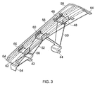
- annulus filler assembly is shown in a second stage of assembly.
- An annulus lid 56 is provided, which is constructed from a carbon-fibre reinforced plastic composite material and having a radially outwardly facing surface 58 for forming the inner wall of the flow annulus.
- the annulus lid 56 comprises three apertures 60 extending therethrough and a channel 62 running axially through the radially outwardly facing surface 58.
- Each axial end of the annulus lid 56 is provided with a tongue 64 which is received under a lip portion of an adjacent casing component, such as the cover portion 28 and rotating seal element 34 as shown in Figure 1 .
- the annulus lid may alternatively be made from a metallic material.
- the annulus lid 56 is located onto the frame 40 such that the three connection portions 46 are received through the apertures 60.
- the shoulders 48 of each connection portion 46 sit substantially flush with the radially outwardly facing surface 58 and a base of the recess 49 of the connection portion sits substantially flush with a base of the channel 62.
- each aperture 60 may comprise two distinct openings 66 on either side of the channel 62 for receiving each of the shoulders 48 of a connection portion 46.
- the base of the recess 49 is separated from the channel 62 by the base of the channel.
- the shoulders 48 are radially taller so that they again sit flush with the radially outwardly facing surface 58.
- the shoulders 48 and optionally the base of the recess 49 of the frame 40 are visible from radially outwards of the surface 58, thus providing a visual confirmation that the connection portions 46 are correctly located in the apertures 60.
- annulus filler assembly is shown in a final stage of assembly.
- An elongate slider element 68 which is sized to be received in the channel 62 is introduced into the channel 62 by sliding the slider element 68 from an axially foremost end of the annulus lid 56 towards an axially rearmost end of the annulus lid 56, as indicated by arrow 70.
- the slider element 68 has a degree of flexibility which allows the slider element to form to the curvature of the annulus lid 56.
- the slider element 68 As the slider element 68 is slid through the channel 62 it passes through the shoulders 66 of each connection portion in turn.
- the slider element 68 has a male dovetail cross-section, such that when the slider element 68 is received in the connection portion 46 the two elements interlock to prevent the connection portion 46 from being withdrawn through the aperture 60.
- Each axial end of the slider element 68 is provided with a bifurcated tongue 72.
- the tongues 72 are received under a lip portion of an adjacent casing component, such as the cover portion 28 and rotating seal element 34 as shown in Figure 1 .
- the cover portion 28 and rotating seal element 34 fix the axial position of the slider element 68 in relation to the annulus lid 56 and thus prevent movement during operation.
- the shoulders 48 of the connection portions 46 sit substantially flush with the radially outwardly facing surface 58. This therefore allows visual inspection before sliding the slider element 68 through the channel 62.
- connection portions 46 are not maintained in the correct position as the slider element 68 is slid through the channel 62, depending on the degree of misalignment, the following outcomes will result:
- the slider element 68 is also provided with three recessed portions 74 spaced across the axial length of the slider element 68.
- the spacing between the recessed portions 74 corresponds to the spacing between both the apertures 60 and the connection portions 46.
- the recessed portions are offset from both the apertures 60 and the connection portions 46 when the slider element 68 is in its operative position wherein the tongues 72 of the slider element are axially aligned with the tongues 64 of the annulus lid 56.
- the recessed portions 74 have the shoulders of the dovetail cross-section removed so that the slider element 68 is narrower along these portions than the distance between the shoulders 48 of the connection portion 46. Therefore, when the recessed portions 74 are aligned in this manner, the slider portion does not interlock with the connection portion 46 and the connection portion 46 can be withdrawn through the aperture 60, thus allowing the removal of the annulus lid 56 from the frame 40 without having to fully extract the slider element 68 from the channel 62.
- connection portion 46 is introduced into the aperture 60 when the recessed portions 74 are aligned with the apertures 60 and then the slider element is slid into the operative position to lock the connection portions 46 and prevent subsequent withdrawal.
- the shoulders 48 of the connection portions 46 sit substantially flush with the radially outwardly facing surface 58. If the shoulders 48 of the connection portions 46 are not visible when the slider element 68 is in the operative position, it is clear that the annulus lid 56 is not correctly connected to the frame 40. Therefore the requirement for visual inspection during all stages of assembly is satisfied with this technique also.
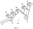
- FIG 5 shows an alternative embodiment of a frame 140 for an annulus filler in accordance with a first embodiment of the invention.
- the frame 140 has five connection portions 146 supported above the first and second hook elements 42, 44 (which are essentially identical to those of the frame of Figure 2 ).
- the slider and lid of this annulus filler though not shown in the drawings, will be appropriately configured to interlock with the five connection portions 146, in a similar manner to that described for the embodiment of Figure 2 . Because the slider and lid are supported in more places, the stresses and strains in the lid will be reduced, compared with the embodiment having three connector portions.
- FIG 6 shows the underside of an alternative embodiment of a lid 156 for an annulus filler in accordance with a first aspect of the invention.
- the lid 156 comprises three apertures 60 extending therethrough, and a channel 62 running axially.
- the lid 156 comprises longitudinal ribs 180, which add stiffness to the lid and thereby lower the stresses therein. It will be understood that in other embodiments, different numbers or configurations of ribs or corrugations may be provided to achieve the same result.
- Figure 7 shows an alternative embodiment of an annulus filler in accordance with a first aspect of the invention.
- this embodiment is similar to that shown in Figure 4 , but the frame 240 of the annulus filler, instead of having first and second hook elements 42, 44 as in Figure 4 , has first and second mounting features 282, 284 comprising holes 286, 288.
- radial bolts extend through the holes 286, 288 to secure the frame 240 to the fan disc. These radial bolts could form part of an axial retention system as described in our pending European patent application EP10168820.2 .
- the securing hooks 42, 44 may face each other.
- the interaction of the slider 68 and the annulus lid 56 and the connection portion 48 may be used to 'lock' the slider and lid in position through centrifugal force.
- the hooks 42, 44 face away from each other and the lip 54 becomes a secondary locking mechanism.
Landscapes
- Engineering & Computer Science (AREA)
- Mechanical Engineering (AREA)
- General Engineering & Computer Science (AREA)
- Structures Of Non-Positive Displacement Pumps (AREA)
- Turbine Rotor Nozzle Sealing (AREA)
Abstract
Description
- The present invention relates to an annulus filler assembly for a turbomachine, in particular the bypass fan assembly of a turbo fan engine.
- A conventional turbo fan engine uses the core engine to drive a bypass fan mounted near the engine intake. Fan blades on the bypass fan drive a core flow into the core engine and a bypass flow around the core engine. The bypass flow combines downstream with the core exhaust flow to provide propulsive thrust.
- A casing assembly extends around the outside of the fan to provide an outer wall of a flow annulus through the fan. The fan blades themselves are not normally provided with blade platforms, and so a number of separate circumferential wall inserts or "annulus fillers" are mounted on the outside of the fan rotor disc, in between the fan blades, to form the inner wall of the flow annulus through the fan.
- The annulus fillers are typically mounted on the fan rotor disc using a hook arrangement, such as the one described in International Application
PCT/GB93/00372 WO93/21425 - A similar configuration is shown in
Figure 1 . Ablade 2 is connected to adisc 4 at a radially outer face of thedisc 4 by an interlocking configuration, such as a dovetail joint. A plurality ofblades 2 are assembled onto thedisc 4 around the circumference of thedisc 4 to form a rotor. As described previously, an annulus filler 6 is provided betweenadjacent blades 2 so as to form the inner wall of the flow annulus through the fan. The annulus filler 6 is mounted to the disc by a pair ofannulus filler hooks shaped disc hooks adjacent blades 2. To ensure that theannulus filler hooks disc hooks disc 4 is fixed by a nosecone support ring 16. The nosecone support ring 16 covers the full circumference of the rotor and retains each of the annulus fillers 6. The nosecone support ring 16 is connected to anarm 18 of the disc and also to anarm 20 of the annulus filler 6. Consequently, the axial position of the annulus filler 6 is fixed so that the hooks remain engaged. During operation, the nosecone support ring 16 also bears a component of the centrifugal load of the annulus filler 6 which creates hoop stress in the nosecone support ring 16. - The nose cone support ring also functions as the primary fixation point for a nose cone of the turbomachine. The nose cone creates smooth airflow into the fan, particularly at the root of the blades, and also must be capable of withstanding bird strikes and preventing build up of ice. The
nose cone 22 is located on anannular shoulder 24 of the nosecone support ring 16 and is connected at positions around the nosecone support ring 16 via abuttingradial flanges 26. - The connection between the nose
cone support ring 16 and thenose cone 22 is enclosed by acover portion 28. The forward (upstream) axial end of the annulus filer 6 has a tongue portion which is received under alip portion 32 of thecover portion 28. A similar arrangement is provided at the opposite axial end for mating with a rotatingseal element 34. - A hook-type mounting arrangement such as the one described in International Application
PCT/GB93/00372 Figure 1 requires that dedicated, load-bearing attachment features such as hooks must be formed on the outside of a forged fan rotor disc and this adds to the cost and complexity of manufacturing the fan rotor disc. - In addition, safely engaging the hooks with one another may be difficult and time-consuming because, in practice, the hooks tend to be obscured from view by the adjacent blades and by the annulus filler itself during assembly. Failure to safely engage the hooks increases the risk of annulus filler detachment under a centrifugal load during rotation of the fan.
- During a bird strike or fan blade off (FBO) event, a fan blade may be deflected and apply a circumferential load to an adjacent annulus filler. Tests have shown that some prior art annulus filler inserts secured using hook style fixings may be vulnerable to detachment under these circumferential loads.
- The present invention seeks to provide an improved annulus filler assembly, and in particular seeks to provide an annulus filler assembly which addresses one or more of the specific problems referred to above.
- According to a first aspect of the invention there is provided an annulus filler assembly for a rotor of a turbomachine, the assembly comprising: an annulus lid having a radially outwardly facing surface for forming an inner wall of a flow annulus of the rotor and a radially inwardly facing surface; and a frame for supporting the annulus lid, the frame being mountable to a disc of the rotor such that the annulus lid is spaced away from the disc, wherein the frame comprises a connection portion which, in use, passes through an aperture in the annulus lid from the radially inwardly facing surface towards the radially outwardly facing surface such that at least a portion of the connection portion is visible from the radially outwardly facing surface; the assembly further comprising a locking element which locks the connection portion to the annulus lid via the visible portion of the connection portion.
- The annulus filler assembly of the present invention therefore provides allows visual inspection of the connections between the constituent components at each stage of assembly. This therefore removes the potential for mal-assembly which could lead to the disconnection of the annulus filler assembly when in service.
- The frame may be narrower than the annulus lid in a circumferential aspect.
- The frame may comprise a hook portion for mounting the frame to the disc of the rotor.
- The annulus lid and frame may be constructed from different materials.
- The frame may be constructed from metal.
- The metal frame is advantageous in the event of a fan blade off event. Here, the metal frame provides some degree of flexibility which would allow the annulus filler assembly to rotate when forced by a deflecting blade. Also if the annulus filler assembly were to fail as a result of a deflecting blade, it is likely that only the annulus lid would be disconnected. Therefore the mass and energy of the debris will be reduced, thus limiting damage.
- The annulus lid may be constructed from a composite material.
- The connection portion and locking element may comprise complementary interlocking surfaces which when interlocked prevent the connection portion from being withdrawn through the aperture.
- The connection portion and locking element may form a dovetail joint.
- The aperture may comprise first and second openings through which first and second portions of the connection portion pass and wherein the locking element is inserted between the first and second portions of the connection portion.
- The annulus lid may comprise a recess formed in its radially outwardly facing surface for receiving the locking element such that the locking element and radially outwardly facing surface form a substantially continuous inner wall of the flow annulus.
- The recess may be a channel extending in an axial direction along the radially outwardly facing surface and the locking element may be an elongate member slidably received within the channel.
- The first and second openings may be positioned either side of the recess.
- The locking element may be flexible.
- The locking element may lock a plurality of connection portions to the annulus lid.
- According to a second aspect of the invention there is provided a method of assembling a rotor, the method comprising: providing a plurality of annulus filler assemblies as claimed in any one of the preceding claims; coupling the frames of the annulus filler assemblies to a disc of the rotor; coupling a plurality of blades to the disc between adjacent frames; locating the annulus lid of the annulus filler assembly on the frame such that the connection portion passes through the aperture in the annulus lid; and inserting the locking element into the connection portion so as to lock the connection portion to the annulus lid.
- For a better understanding of the present invention, and to show more clearly how it may be carried into effect, reference will now be made by way of example, to the following drawings, in which:
-
Figure 1 is a side cross-sectional view of a prior art annulus filler assembly; -
Figure 2 is a perspective view of an annulus filler assembly in accordance with a first aspect of the invention in a first stage of assembly; -
Figure 3 is a perspective view of the annulus filler assembly ofFigure 2 in a second stage of assembly; -
Figure 4 is a perspective view of the annulus filler assembly ofFigure 2 in a final stage of assembly; -
Figure 5 is a perspective view of an alternative embodiment of an annulus filler in accordance with a first aspect of the invention in a first state of assembly; -
Figure 6 is a perspective view of part of an alternative embodiment of an annulus filler in accordance with a first aspect of the invention; and -
Figure 7 is a perspective view of the annulus filler assembly ofFigure 6 in a final stage of assembly. -
Figure 2 shows an annulus filler assembly in accordance with a first aspect of the invention. The annulus filler assembly comprises aframe 40 having afirst hook element 42 and asecond hook element 44 for attachment to correspondingly shaped hook elements on a disc; for example thehooks Figure 1 . - The
frame 40 comprises a pair ofupstanding members 50 extending substantially from the first andsecond hook elements member 52 which joins the first andsecond hook elements frame 40 is constructed from sheet metal and therefore the bridgingmember 52 provides a degree of flexibility between the first andsecond hook elements second hook elements - The
frame 40 comprises threeconnection portions 46 which are supported above the first andsecond hook elements connection portions 46 are supported on the pair ofupstanding members 50 and the third is supported by the bridgingmember 52. Although threeconnection portions 46 are shown inFigure 2 , any appropriate number ofconnection portions 46 and a correspondingly arranged frame may be provided, in alternative applications. - Each
connection portion 46 has a cross-section which forms one half of an interlocking connection. For example, as shown inFigure 2 , eachconnection portion 46 has twoshoulders 48 and arecess 49 therebetween, forming a female half of a dovetail joint. - An
arm 54 extends axially from thefirst hook element 42. Thearm 54 is connected to or abuts with a thrust ring, such as the nosecone support ring 16 shown inFigure 1 , which acts to position the annulus filler axially and to maintain engagement of the first andsecond hook elements - The width w of the
frame 40 is narrower than the gap between adjacent blades. This allows theframe 40 to be engaged with the disc prior to fitting of the blades and subsequent disassembly can be performed without removal of theframe 40 from the disc. As a result, it is possible to visually inspect the first andsecond hook elements - Alternatively, the
frame 40 may be connected after fitting of the blades. Since theframe 40 is narrower than the gap between adjacent blades, there is a gap either side of theframe 40 which again allows visual inspection of the first andsecond hook elements - It should be appreciated that not all of the
frame 40 need be narrower than the gap between adjacent blades and that alternatively only those elements which would otherwise restrict the view of the first andsecond hook elements upstanding members 50 and the bridgingmember 52. As can be seen inFigure 2 , theconnection portions 46 do not directly overlie the first andsecond hook elements connection portions 46 were of comparable width to the gap between adjacent blades. - Referring now to
Figure 3 , the annulus filler assembly is shown in a second stage of assembly. Anannulus lid 56 is provided, which is constructed from a carbon-fibre reinforced plastic composite material and having a radially outwardly facingsurface 58 for forming the inner wall of the flow annulus. Theannulus lid 56 comprises threeapertures 60 extending therethrough and achannel 62 running axially through the radially outwardly facingsurface 58. Each axial end of theannulus lid 56 is provided with atongue 64 which is received under a lip portion of an adjacent casing component, such as thecover portion 28 androtating seal element 34 as shown inFigure 1 . In other embodiments the annulus lid may alternatively be made from a metallic material. - The
annulus lid 56 is located onto theframe 40 such that the threeconnection portions 46 are received through theapertures 60. Theshoulders 48 of eachconnection portion 46 sit substantially flush with the radially outwardly facingsurface 58 and a base of therecess 49 of the connection portion sits substantially flush with a base of thechannel 62. - Alternatively, each
aperture 60 may comprise twodistinct openings 66 on either side of thechannel 62 for receiving each of theshoulders 48 of aconnection portion 46. In this configuration the base of therecess 49 is separated from thechannel 62 by the base of the channel. To compensate for the offset in the radial position of the base of therecess 49, theshoulders 48 are radially taller so that they again sit flush with the radially outwardly facingsurface 58. - In either configuration, the
shoulders 48 and optionally the base of therecess 49 of theframe 40 are visible from radially outwards of thesurface 58, thus providing a visual confirmation that theconnection portions 46 are correctly located in theapertures 60. - Referring now to
Figure 4 , the annulus filler assembly is shown in a final stage of assembly. Anelongate slider element 68 which is sized to be received in thechannel 62 is introduced into thechannel 62 by sliding theslider element 68 from an axially foremost end of theannulus lid 56 towards an axially rearmost end of theannulus lid 56, as indicated byarrow 70. Theslider element 68 has a degree of flexibility which allows the slider element to form to the curvature of theannulus lid 56. - As the
slider element 68 is slid through thechannel 62 it passes through theshoulders 66 of each connection portion in turn. Theslider element 68 has a male dovetail cross-section, such that when theslider element 68 is received in theconnection portion 46 the two elements interlock to prevent theconnection portion 46 from being withdrawn through theaperture 60. Each axial end of theslider element 68 is provided with abifurcated tongue 72. Similarly to thetongues 64 of theannulus lid 56, thetongues 72 are received under a lip portion of an adjacent casing component, such as thecover portion 28 androtating seal element 34 as shown inFigure 1 . Thecover portion 28 androtating seal element 34 fix the axial position of theslider element 68 in relation to theannulus lid 56 and thus prevent movement during operation. - As discussed previously, when correctly located, the
shoulders 48 of theconnection portions 46 sit substantially flush with the radially outwardly facingsurface 58. This therefore allows visual inspection before sliding theslider element 68 through thechannel 62. - Where the
connection portions 46 are not maintained in the correct position as theslider element 68 is slid through thechannel 62, depending on the degree of misalignment, the following outcomes will result: - • If misalignment is minor, the
slider element 68 will be received sufficiently within theconnection portion 46 and thus force theconnection portion 46 radially outwards (or theannulus lid 56 radially inwards) through contact between theshoulders 48 of theconnection portion 46 and theslider element 68, particularly thetongue 72 of theslider element 68, and thus any misalignment will be corrected; - • If misalignment is moderate, the
tongue 72 of theslider element 68 will contact theshoulders 48 and prevent theslider element 68 from sliding further; - • If the misalignment is severe, an interlocking connection will not be formed and instead the
slider element 68 will pass over theconnection portion 46 withdrawing theconnection portion 46 andshoulders 48 out of theaperture 60. - In the latter case where an interlocking connection is not formed, it is immediately evident from a visual inspection of the radially outwardly facing
surface 58 that this is the case since theshoulders 48 are not visible, or if they are visible they are clearly not flush with the radially outwardly facingsurface 58. A visual inspection of the radially outwardly facingsurface 58 therefore confirms whether theannulus lid 56 is correctly connected to theframe 40 and the assembly is not put into service unless all of theshoulders 48 of theconnection portions 46 are visible and flush with the radially outwardly facingsurface 58. - The
slider element 68 is also provided with three recessedportions 74 spaced across the axial length of theslider element 68. The spacing between the recessedportions 74 corresponds to the spacing between both theapertures 60 and theconnection portions 46. The recessed portions are offset from both theapertures 60 and theconnection portions 46 when theslider element 68 is in its operative position wherein thetongues 72 of the slider element are axially aligned with thetongues 64 of theannulus lid 56. By sliding theslider element 68 out of the annulus lid 56 (in the opposite direction to arrow 70) by a distance equal to the offset, the recessedportions 74 can be aligned with theconnection portions 46 andapertures 60. The recessedportions 74 have the shoulders of the dovetail cross-section removed so that theslider element 68 is narrower along these portions than the distance between theshoulders 48 of theconnection portion 46. Therefore, when the recessedportions 74 are aligned in this manner, the slider portion does not interlock with theconnection portion 46 and theconnection portion 46 can be withdrawn through theaperture 60, thus allowing the removal of theannulus lid 56 from theframe 40 without having to fully extract theslider element 68 from thechannel 62. - The reversed technique can also be used to connect the
annulus lid 56 to theframe 40. Here, theconnection portion 46 is introduced into theaperture 60 when the recessedportions 74 are aligned with theapertures 60 and then the slider element is slid into the operative position to lock theconnection portions 46 and prevent subsequent withdrawal. When correctly located, theshoulders 48 of theconnection portions 46 sit substantially flush with the radially outwardly facingsurface 58. If theshoulders 48 of theconnection portions 46 are not visible when theslider element 68 is in the operative position, it is clear that theannulus lid 56 is not correctly connected to theframe 40. Therefore the requirement for visual inspection during all stages of assembly is satisfied with this technique also. -
Figure 5 shows an alternative embodiment of aframe 140 for an annulus filler in accordance with a first embodiment of the invention. In contrast to theframe 40 shown inFigure 2 , theframe 140 has fiveconnection portions 146 supported above the first andsecond hook elements 42, 44 (which are essentially identical to those of the frame ofFigure 2 ). It will be understood that the slider and lid of this annulus filler, though not shown in the drawings, will be appropriately configured to interlock with the fiveconnection portions 146, in a similar manner to that described for the embodiment ofFigure 2 . Because the slider and lid are supported in more places, the stresses and strains in the lid will be reduced, compared with the embodiment having three connector portions. -
Figure 6 shows the underside of an alternative embodiment of alid 156 for an annulus filler in accordance with a first aspect of the invention. As with thelid 56 shown inFigure 3 , thelid 156 comprises threeapertures 60 extending therethrough, and achannel 62 running axially. In contrast to thelid 56 ofFigure 3 , thelid 156 compriseslongitudinal ribs 180, which add stiffness to the lid and thereby lower the stresses therein. It will be understood that in other embodiments, different numbers or configurations of ribs or corrugations may be provided to achieve the same result. -
Figure 7 shows an alternative embodiment of an annulus filler in accordance with a first aspect of the invention. In most respects, this embodiment is similar to that shown inFigure 4 , but theframe 240 of the annulus filler, instead of having first andsecond hook elements Figure 4 , has first and second mounting features 282, 284 comprisingholes holes frame 240 to the fan disc. These radial bolts could form part of an axial retention system as described in our pending European patent applicationEP10168820.2 - It will be appreciated that variations and modifications may be made to the specific arrangement described, without departing from the invention.
- For instance, the securing hooks 42, 44 may face each other. The interaction of the
slider 68 and theannulus lid 56 and theconnection portion 48 may be used to 'lock' the slider and lid in position through centrifugal force. - In another arrangement (not shown in the drawings) the
hooks lip 54 becomes a secondary locking mechanism.
Claims (15)
- An annulus filler assembly for a rotor of a turbomachine, the assembly comprising:an annulus lid having a radially outwardly facing surface for forming an inner wall of a flow annulus of the rotor and a radially inwardly facing surface; anda frame for supporting the annulus lid, the frame being mountable to a disc of the rotor such that the annulus lid is spaced away from the disc,wherein the frame comprises a connection portion which, in use, passes through an aperture in the annulus lid from the radially inwardly facing surface towards the radially outwardly facing surface such that at least a portion of the connection portion is visible from the radially outwardly facing surface;the assembly further comprising a locking element which locks the connection portion to the annulus lid via the visible portion of the connection portion.
- An annulus filler assembly as claimed in claim 1, wherein the frame is narrower than the annulus lid in a circumferential aspect.
- An annulus filler assembly as claimed in claim 1 or 2, wherein the frame comprises a hook portion (42, 44) for mounting the frame to the disc of the rotor.
- An annulus filler assembly as claimed in any one of the preceding claims, wherein the annulus lid and frame are constructed from different materials.
- An annulus filler assembly as claimed in any one of the preceding claims, wherein the frame (40) is constructed from metal.
- An annulus filler assembly as claimed in any one of the preceding claims, wherein the annulus lid (56) is constructed from a composite material.
- An annulus filler as claimed in any one of the preceding claims, wherein the connection portion and locking element comprise complementary interlocking surfaces (46, 68) which when interlocked prevent the connection portion from being withdrawn through the aperture.
- An annulus filler assembly as claimed in claim 7, wherein the connection portion and locking element form a dovetail joint.
- An annulus filler assembly as claimed in any one of the preceding claims, wherein the aperture comprises first and second openings through which first and second portions of the connection portion pass and wherein the locking element is inserted between the first and second portions of the connection portion.
- An annulus filler assembly as claimed in any one of the preceding claims, wherein the annulus lid comprises a recess formed in its radially outwardly facing surface for receiving the locking element such that the locking element and radially outwardly facing surface form a substantially continuous inner wall of the flow annulus.
- An annulus filler assembly as claimed in claim 10, wherein the recess is a channel extending in an axial direction along the radially outwardly facing surface and the locking element is an elongate member slidably received within the channel.
- An annulus filler assembly as claimed in any one of the preceding claims, wherein the locking element is flexible.
- An annulus filler assembly as claimed in any one of the preceding claims, wherein the locking element locks a plurality of connection portions to the annulus lid.
- A turbomachine comprising an annulus filler assembly as claimed in any one of the preceding claims.
- A method of assembling a rotor, the method comprising:providing a plurality of annulus filler assemblies as claimed in any one of the preceding claims;coupling the frames of the annulus filler assemblies to a disc of the rotor;coupling a plurality of blades to the disc between adjacent frames;locating the annulus lid of the annulus filler assembly on the frame such that the connection portion passes through the aperture in the annulus lid; andinserting the locking element into the connection portion so as to lock the connection portion to the annulus lid.
Applications Claiming Priority (1)
| Application Number | Priority Date | Filing Date | Title |
|---|---|---|---|
| GB0922422A GB0922422D0 (en) | 2009-12-23 | 2009-12-23 | Annulus Filler Assembly for a Rotor of a Turbomachine |
Publications (2)
| Publication Number | Publication Date |
|---|---|
| EP2372098A2 true EP2372098A2 (en) | 2011-10-05 |
| EP2372098A3 EP2372098A3 (en) | 2014-08-20 |
Family
ID=41717402
Family Applications (1)
| Application Number | Title | Priority Date | Filing Date |
|---|---|---|---|
| EP10195223.2A Withdrawn EP2372098A3 (en) | 2009-12-23 | 2010-12-15 | Annulus filler assembly for a rotor of a turbomachine |
Country Status (3)
| Country | Link |
|---|---|
| US (1) | US8851850B2 (en) |
| EP (1) | EP2372098A3 (en) |
| GB (1) | GB0922422D0 (en) |
Cited By (2)
| Publication number | Priority date | Publication date | Assignee | Title |
|---|---|---|---|---|
| DE102016009311A1 (en) | 2016-07-30 | 2018-02-01 | Alexander Prokofiev | Solar module unit |
| EP3663530A1 (en) * | 2018-12-07 | 2020-06-10 | Safran Aircraft Engines | Fan comprising an inter-blade platform |
Families Citing this family (11)
| Publication number | Priority date | Publication date | Assignee | Title |
|---|---|---|---|---|
| US9366185B2 (en) * | 2012-09-28 | 2016-06-14 | United Technologies Corporation | Flexible connection between a wall and a case of a turbine engine |
| US9399922B2 (en) * | 2012-12-31 | 2016-07-26 | General Electric Company | Non-integral fan blade platform |
| US9682450B2 (en) * | 2013-01-11 | 2017-06-20 | United Technologies Corporation | Gas turbine engine nose cone attachment configuration |
| US20160053636A1 (en) * | 2013-03-15 | 2016-02-25 | United Technologies Corporation | Injection Molded Composite Fan Platform |
| GB201314541D0 (en) * | 2013-08-14 | 2013-09-25 | Rolls Royce Plc | Annulus Filler |
| GB201314542D0 (en) * | 2013-08-14 | 2013-09-25 | Rolls Royce Plc | Annulus Filler |
| US10227884B2 (en) | 2013-09-18 | 2019-03-12 | United Technologies Corporation | Fan platform with leading edge tab |
| FR3021694B1 (en) * | 2014-05-28 | 2019-11-01 | Safran Aircraft Engines | PLATFORM FOR AUBAGEE WHEEL |
| FR3039854B1 (en) * | 2015-08-03 | 2019-08-16 | Safran Aircraft Engines | INTERMEDIATE CASE FOR TURBOMACHINE HAVING IMPROVED FASTENING MEANS |
| US10458425B2 (en) | 2016-06-02 | 2019-10-29 | General Electric Company | Conical load spreader for composite bolted joint |
| US12012857B2 (en) | 2022-10-14 | 2024-06-18 | Rtx Corporation | Platform for an airfoil of a gas turbine engine |
Citations (2)
| Publication number | Priority date | Publication date | Assignee | Title |
|---|---|---|---|---|
| WO1993021425A1 (en) | 1992-04-16 | 1993-10-28 | Rolls-Royce Plc | Rotors for gas turbine engines |
| EP1016882A2 (en) | 1998-12-31 | 2000-07-05 | Integrated Detector & Electronics AS | Output circuit for a charge detector |
Family Cites Families (8)
| Publication number | Priority date | Publication date | Assignee | Title |
|---|---|---|---|---|
| GB1232506A (en) * | 1969-10-28 | 1971-05-19 | ||
| GB2171151B (en) | 1985-02-20 | 1988-05-18 | Rolls Royce | Rotors for gas turbine engines |
| EP1124038A1 (en) | 2000-02-09 | 2001-08-16 | Siemens Aktiengesellschaft | Turbine blading |
| GB2414521B (en) * | 2004-05-28 | 2007-04-11 | Rolls Royce Plc | Rotor assembly and annulus filler for gas turbine engine compressor |
| GB2425155B (en) | 2005-04-13 | 2007-09-19 | Rolls Royce Plc | A mounting arrangement |
| GB0802834D0 (en) | 2008-02-18 | 2008-03-26 | Rolls Royce Plc | Annulus filler |
| GB0814718D0 (en) | 2008-08-13 | 2008-09-17 | Rolls Royce Plc | Annulus filler |
| GB0908422D0 (en) | 2009-05-18 | 2009-06-24 | Rolls Royce Plc | Annulus filler |
-
2009
- 2009-12-23 GB GB0922422A patent/GB0922422D0/en not_active Ceased
-
2010
- 2010-12-15 EP EP10195223.2A patent/EP2372098A3/en not_active Withdrawn
- 2010-12-15 US US12/968,962 patent/US8851850B2/en not_active Expired - Fee Related
Patent Citations (2)
| Publication number | Priority date | Publication date | Assignee | Title |
|---|---|---|---|---|
| WO1993021425A1 (en) | 1992-04-16 | 1993-10-28 | Rolls-Royce Plc | Rotors for gas turbine engines |
| EP1016882A2 (en) | 1998-12-31 | 2000-07-05 | Integrated Detector & Electronics AS | Output circuit for a charge detector |
Cited By (4)
| Publication number | Priority date | Publication date | Assignee | Title |
|---|---|---|---|---|
| DE102016009311A1 (en) | 2016-07-30 | 2018-02-01 | Alexander Prokofiev | Solar module unit |
| EP3663530A1 (en) * | 2018-12-07 | 2020-06-10 | Safran Aircraft Engines | Fan comprising an inter-blade platform |
| FR3089548A1 (en) * | 2018-12-07 | 2020-06-12 | Safran Aircraft Engines | BLOWER COMPRISING AN INTER-BLADE PLATFORM FIXED UPWARD BY A RUBBER |
| US11162418B2 (en) | 2018-12-07 | 2021-11-02 | Safran Aircraft Engines | Fan comprising an inter-blade platform attached upstream by a ferrule |
Also Published As
| Publication number | Publication date |
|---|---|
| US20110146299A1 (en) | 2011-06-23 |
| GB0922422D0 (en) | 2010-02-03 |
| US8851850B2 (en) | 2014-10-07 |
| EP2372098A3 (en) | 2014-08-20 |
Similar Documents
| Publication | Publication Date | Title |
|---|---|---|
| US8851850B2 (en) | Annulus filler assembly for a rotor of a turbomachine | |
| US9752592B2 (en) | Turbine shroud | |
| US8128354B2 (en) | Gas turbine engine | |
| CN101956575B (en) | Turbine bucket lockwire rotation prevention | |
| EP2677121B1 (en) | A catcher ring arrangement | |
| EP2236756A2 (en) | Gas turbine having seal assembly with side plate and seal | |
| KR20110126708A (en) | Rotor sections for rotors of turbomachines and rotor blades for turbomachines | |
| US8596981B2 (en) | Annulus filler for a gas turbine engine | |
| EP2562355A2 (en) | Coupled blade platforms and methods of sealing | |
| US8684683B2 (en) | Gas turbine nozzle attachment scheme and removal/installation method | |
| US8858180B2 (en) | Annulus filler element for a rotor of a turbomachine | |
| EP2236768A2 (en) | Turbomachine seal assembly | |
| RU2436965C2 (en) | Device for attachment of guide vanes of turbine, turbine and aircraft engine with such equipment | |
| MX2013001624A (en) | Inter stage seal housing having a replaceable wear strip. | |
| WO2016148692A1 (en) | Stator vane dampening system usable within a turbine engine | |
| US8277190B2 (en) | Turbomachine rotor assembly and method | |
| US8926279B2 (en) | Propeller hub | |
| EP2581559A2 (en) | Adaptor assembly for coupling turbine blades to rotor disks | |
| US8753075B2 (en) | Fan case assembly and method | |
| CN106089439B (en) | Gas turbine disassembly method | |
| CN106050323B (en) | Blade-mounted multistage turbine interstage seal and method of assembly | |
| EP1165940B1 (en) | Axial dovetail segment for securing a bucket to a turbine wheel and methods of installation | |
| EP4174290B1 (en) | Support plate for a gas turbine engine casing flange | |
| US10920598B2 (en) | Rotor assembly cover plate | |
| Care | Hoyland et al. |
Legal Events
| Date | Code | Title | Description |
|---|---|---|---|
| PUAI | Public reference made under article 153(3) epc to a published international application that has entered the european phase |
Free format text: ORIGINAL CODE: 0009012 |
|
| AK | Designated contracting states |
Kind code of ref document: A2 Designated state(s): AL AT BE BG CH CY CZ DE DK EE ES FI FR GB GR HR HU IE IS IT LI LT LU LV MC MK MT NL NO PL PT RO RS SE SI SK SM TR |
|
| AX | Request for extension of the european patent |
Extension state: BA ME |
|
| PUAL | Search report despatched |
Free format text: ORIGINAL CODE: 0009013 |
|
| AK | Designated contracting states |
Kind code of ref document: A3 Designated state(s): AL AT BE BG CH CY CZ DE DK EE ES FI FR GB GR HR HU IE IS IT LI LT LU LV MC MK MT NL NO PL PT RO RS SE SI SK SM TR |
|
| AX | Request for extension of the european patent |
Extension state: BA ME |
|
| RIC1 | Information provided on ipc code assigned before grant |
Ipc: F01D 11/00 20060101AFI20140715BHEP |
|
| RAP1 | Party data changed (applicant data changed or rights of an application transferred) |
Owner name: ROLLS-ROYCE PLC |
|
| STAA | Information on the status of an ep patent application or granted ep patent |
Free format text: STATUS: THE APPLICATION IS DEEMED TO BE WITHDRAWN |
|
| 18D | Application deemed to be withdrawn |
Effective date: 20150221 |