EP2371878A1 - Polymer compound and organic light-emitting device including the same - Google Patents
Polymer compound and organic light-emitting device including the same Download PDFInfo
- Publication number
- EP2371878A1 EP2371878A1 EP11160612A EP11160612A EP2371878A1 EP 2371878 A1 EP2371878 A1 EP 2371878A1 EP 11160612 A EP11160612 A EP 11160612A EP 11160612 A EP11160612 A EP 11160612A EP 2371878 A1 EP2371878 A1 EP 2371878A1
- Authority
- EP
- European Patent Office
- Prior art keywords
- group
- polymer
- substituted
- unsubstituted
- organic light
- Prior art date
- Legal status (The legal status is an assumption and is not a legal conclusion. Google has not performed a legal analysis and makes no representation as to the accuracy of the status listed.)
- Granted
Links
- 0 *C1=C(c2ccccc2)[Si](*)(*)C(c2ccccc2)=C1* Chemical compound *C1=C(c2ccccc2)[Si](*)(*)C(c2ccccc2)=C1* 0.000 description 8
- UCLXUPRIAJUZED-UHFFFAOYSA-N Cc1ccc(-c2ccc(-c3ccc(C)[s]3)[s]2)[s]1 Chemical compound Cc1ccc(-c2ccc(-c3ccc(C)[s]3)[s]2)[s]1 UCLXUPRIAJUZED-UHFFFAOYSA-N 0.000 description 1
- DKHDQTBBXQMFPP-UHFFFAOYSA-N Cc1ccc(-c2ccc(C)[s]2)[s]1 Chemical compound Cc1ccc(-c2ccc(C)[s]2)[s]1 DKHDQTBBXQMFPP-UHFFFAOYSA-N 0.000 description 1
Images

Classifications
-
- H—ELECTRICITY
- H10—SEMICONDUCTOR DEVICES; ELECTRIC SOLID-STATE DEVICES NOT OTHERWISE PROVIDED FOR
- H10K—ORGANIC ELECTRIC SOLID-STATE DEVICES
- H10K85/00—Organic materials used in the body or electrodes of devices covered by this subclass
- H10K85/10—Organic polymers or oligomers
- H10K85/151—Copolymers
-
- C—CHEMISTRY; METALLURGY
- C09—DYES; PAINTS; POLISHES; NATURAL RESINS; ADHESIVES; COMPOSITIONS NOT OTHERWISE PROVIDED FOR; APPLICATIONS OF MATERIALS NOT OTHERWISE PROVIDED FOR
- C09K—MATERIALS FOR MISCELLANEOUS APPLICATIONS, NOT PROVIDED FOR ELSEWHERE
- C09K11/00—Luminescent materials, e.g. electroluminescent or chemiluminescent
- C09K11/06—Luminescent materials, e.g. electroluminescent or chemiluminescent containing organic luminescent materials
-
- C—CHEMISTRY; METALLURGY
- C08—ORGANIC MACROMOLECULAR COMPOUNDS; THEIR PREPARATION OR CHEMICAL WORKING-UP; COMPOSITIONS BASED THEREON
- C08G—MACROMOLECULAR COMPOUNDS OBTAINED OTHERWISE THAN BY REACTIONS ONLY INVOLVING UNSATURATED CARBON-TO-CARBON BONDS
- C08G61/00—Macromolecular compounds obtained by reactions forming a carbon-to-carbon link in the main chain of the macromolecule
- C08G61/12—Macromolecular compounds containing atoms other than carbon in the main chain of the macromolecule
-
- C—CHEMISTRY; METALLURGY
- C08—ORGANIC MACROMOLECULAR COMPOUNDS; THEIR PREPARATION OR CHEMICAL WORKING-UP; COMPOSITIONS BASED THEREON
- C08G—MACROMOLECULAR COMPOUNDS OBTAINED OTHERWISE THAN BY REACTIONS ONLY INVOLVING UNSATURATED CARBON-TO-CARBON BONDS
- C08G61/00—Macromolecular compounds obtained by reactions forming a carbon-to-carbon link in the main chain of the macromolecule
- C08G61/12—Macromolecular compounds containing atoms other than carbon in the main chain of the macromolecule
- C08G61/122—Macromolecular compounds containing atoms other than carbon in the main chain of the macromolecule derived from five- or six-membered heterocyclic compounds, other than imides
-
- C—CHEMISTRY; METALLURGY
- C08—ORGANIC MACROMOLECULAR COMPOUNDS; THEIR PREPARATION OR CHEMICAL WORKING-UP; COMPOSITIONS BASED THEREON
- C08G—MACROMOLECULAR COMPOUNDS OBTAINED OTHERWISE THAN BY REACTIONS ONLY INVOLVING UNSATURATED CARBON-TO-CARBON BONDS
- C08G73/00—Macromolecular compounds obtained by reactions forming a linkage containing nitrogen with or without oxygen or carbon in the main chain of the macromolecule, not provided for in groups C08G12/00 - C08G71/00
- C08G73/02—Polyamines
- C08G73/0273—Polyamines containing heterocyclic moieties in the main chain
-
- C—CHEMISTRY; METALLURGY
- C08—ORGANIC MACROMOLECULAR COMPOUNDS; THEIR PREPARATION OR CHEMICAL WORKING-UP; COMPOSITIONS BASED THEREON
- C08G—MACROMOLECULAR COMPOUNDS OBTAINED OTHERWISE THAN BY REACTIONS ONLY INVOLVING UNSATURATED CARBON-TO-CARBON BONDS
- C08G73/00—Macromolecular compounds obtained by reactions forming a linkage containing nitrogen with or without oxygen or carbon in the main chain of the macromolecule, not provided for in groups C08G12/00 - C08G71/00
- C08G73/06—Polycondensates having nitrogen-containing heterocyclic rings in the main chain of the macromolecule
-
- C—CHEMISTRY; METALLURGY
- C08—ORGANIC MACROMOLECULAR COMPOUNDS; THEIR PREPARATION OR CHEMICAL WORKING-UP; COMPOSITIONS BASED THEREON
- C08L—COMPOSITIONS OF MACROMOLECULAR COMPOUNDS
- C08L79/00—Compositions of macromolecular compounds obtained by reactions forming in the main chain of the macromolecule a linkage containing nitrogen with or without oxygen or carbon only, not provided for in groups C08L61/00 - C08L77/00
- C08L79/02—Polyamines
-
- C—CHEMISTRY; METALLURGY
- C08—ORGANIC MACROMOLECULAR COMPOUNDS; THEIR PREPARATION OR CHEMICAL WORKING-UP; COMPOSITIONS BASED THEREON
- C08L—COMPOSITIONS OF MACROMOLECULAR COMPOUNDS
- C08L79/00—Compositions of macromolecular compounds obtained by reactions forming in the main chain of the macromolecule a linkage containing nitrogen with or without oxygen or carbon only, not provided for in groups C08L61/00 - C08L77/00
- C08L79/04—Polycondensates having nitrogen-containing heterocyclic rings in the main chain; Polyhydrazides; Polyamide acids or similar polyimide precursors
-
- H—ELECTRICITY
- H05—ELECTRIC TECHNIQUES NOT OTHERWISE PROVIDED FOR
- H05B—ELECTRIC HEATING; ELECTRIC LIGHT SOURCES NOT OTHERWISE PROVIDED FOR; CIRCUIT ARRANGEMENTS FOR ELECTRIC LIGHT SOURCES, IN GENERAL
- H05B33/00—Electroluminescent light sources
- H05B33/12—Light sources with substantially two-dimensional [2D] radiating surfaces
- H05B33/14—Light sources with substantially two-dimensional [2D] radiating surfaces characterised by the chemical or physical composition or the arrangement of the electroluminescent material, or by the simultaneous addition of the electroluminescent material in or onto the light source
-
- H—ELECTRICITY
- H10—SEMICONDUCTOR DEVICES; ELECTRIC SOLID-STATE DEVICES NOT OTHERWISE PROVIDED FOR
- H10K—ORGANIC ELECTRIC SOLID-STATE DEVICES
- H10K50/00—Organic light-emitting devices
- H10K50/10—OLEDs or polymer light-emitting diodes [PLED]
- H10K50/11—OLEDs or polymer light-emitting diodes [PLED] characterised by the electroluminescent [EL] layers
-
- H—ELECTRICITY
- H10—SEMICONDUCTOR DEVICES; ELECTRIC SOLID-STATE DEVICES NOT OTHERWISE PROVIDED FOR
- H10K—ORGANIC ELECTRIC SOLID-STATE DEVICES
- H10K50/00—Organic light-emitting devices
- H10K50/10—OLEDs or polymer light-emitting diodes [PLED]
- H10K50/14—Carrier transporting layers
- H10K50/15—Hole transporting layers
-
- H—ELECTRICITY
- H10—SEMICONDUCTOR DEVICES; ELECTRIC SOLID-STATE DEVICES NOT OTHERWISE PROVIDED FOR
- H10K—ORGANIC ELECTRIC SOLID-STATE DEVICES
- H10K85/00—Organic materials used in the body or electrodes of devices covered by this subclass
- H10K85/10—Organic polymers or oligomers
- H10K85/111—Organic polymers or oligomers comprising aromatic, heteroaromatic, or aryl chains, e.g. polyaniline, polyphenylene or polyphenylene vinylene
-
- H—ELECTRICITY
- H10—SEMICONDUCTOR DEVICES; ELECTRIC SOLID-STATE DEVICES NOT OTHERWISE PROVIDED FOR
- H10K—ORGANIC ELECTRIC SOLID-STATE DEVICES
- H10K85/00—Organic materials used in the body or electrodes of devices covered by this subclass
- H10K85/10—Organic polymers or oligomers
- H10K85/111—Organic polymers or oligomers comprising aromatic, heteroaromatic, or aryl chains, e.g. polyaniline, polyphenylene or polyphenylene vinylene
- H10K85/113—Heteroaromatic compounds comprising sulfur or selene, e.g. polythiophene
-
- H—ELECTRICITY
- H10—SEMICONDUCTOR DEVICES; ELECTRIC SOLID-STATE DEVICES NOT OTHERWISE PROVIDED FOR
- H10K—ORGANIC ELECTRIC SOLID-STATE DEVICES
- H10K85/00—Organic materials used in the body or electrodes of devices covered by this subclass
- H10K85/10—Organic polymers or oligomers
- H10K85/111—Organic polymers or oligomers comprising aromatic, heteroaromatic, or aryl chains, e.g. polyaniline, polyphenylene or polyphenylene vinylene
- H10K85/115—Polyfluorene; Derivatives thereof
-
- C—CHEMISTRY; METALLURGY
- C08—ORGANIC MACROMOLECULAR COMPOUNDS; THEIR PREPARATION OR CHEMICAL WORKING-UP; COMPOSITIONS BASED THEREON
- C08G—MACROMOLECULAR COMPOUNDS OBTAINED OTHERWISE THAN BY REACTIONS ONLY INVOLVING UNSATURATED CARBON-TO-CARBON BONDS
- C08G2261/00—Macromolecular compounds obtained by reactions forming a carbon-to-carbon link in the main chain of the macromolecule
- C08G2261/30—Monomer units or repeat units incorporating structural elements in the main chain
- C08G2261/31—Monomer units or repeat units incorporating structural elements in the main chain incorporating aromatic structural elements in the main chain
- C08G2261/314—Condensed aromatic systems, e.g. perylene, anthracene or pyrene
- C08G2261/3142—Condensed aromatic systems, e.g. perylene, anthracene or pyrene fluorene-based, e.g. fluorene, indenofluorene, or spirobifluorene
-
- C—CHEMISTRY; METALLURGY
- C08—ORGANIC MACROMOLECULAR COMPOUNDS; THEIR PREPARATION OR CHEMICAL WORKING-UP; COMPOSITIONS BASED THEREON
- C08G—MACROMOLECULAR COMPOUNDS OBTAINED OTHERWISE THAN BY REACTIONS ONLY INVOLVING UNSATURATED CARBON-TO-CARBON BONDS
- C08G2261/00—Macromolecular compounds obtained by reactions forming a carbon-to-carbon link in the main chain of the macromolecule
- C08G2261/30—Monomer units or repeat units incorporating structural elements in the main chain
- C08G2261/31—Monomer units or repeat units incorporating structural elements in the main chain incorporating aromatic structural elements in the main chain
- C08G2261/316—Monomer units or repeat units incorporating structural elements in the main chain incorporating aromatic structural elements in the main chain bridged by heteroatoms, e.g. N, P, Si or B
- C08G2261/3162—Arylamines
-
- C—CHEMISTRY; METALLURGY
- C08—ORGANIC MACROMOLECULAR COMPOUNDS; THEIR PREPARATION OR CHEMICAL WORKING-UP; COMPOSITIONS BASED THEREON
- C08G—MACROMOLECULAR COMPOUNDS OBTAINED OTHERWISE THAN BY REACTIONS ONLY INVOLVING UNSATURATED CARBON-TO-CARBON BONDS
- C08G2261/00—Macromolecular compounds obtained by reactions forming a carbon-to-carbon link in the main chain of the macromolecule
- C08G2261/30—Monomer units or repeat units incorporating structural elements in the main chain
- C08G2261/32—Monomer units or repeat units incorporating structural elements in the main chain incorporating heteroaromatic structural elements in the main chain
- C08G2261/324—Monomer units or repeat units incorporating structural elements in the main chain incorporating heteroaromatic structural elements in the main chain condensed
- C08G2261/3245—Monomer units or repeat units incorporating structural elements in the main chain incorporating heteroaromatic structural elements in the main chain condensed containing nitrogen and oxygen as heteroatoms
-
- C—CHEMISTRY; METALLURGY
- C08—ORGANIC MACROMOLECULAR COMPOUNDS; THEIR PREPARATION OR CHEMICAL WORKING-UP; COMPOSITIONS BASED THEREON
- C08G—MACROMOLECULAR COMPOUNDS OBTAINED OTHERWISE THAN BY REACTIONS ONLY INVOLVING UNSATURATED CARBON-TO-CARBON BONDS
- C08G2261/00—Macromolecular compounds obtained by reactions forming a carbon-to-carbon link in the main chain of the macromolecule
- C08G2261/50—Physical properties
- C08G2261/51—Charge transport
- C08G2261/512—Hole transport
-
- C—CHEMISTRY; METALLURGY
- C09—DYES; PAINTS; POLISHES; NATURAL RESINS; ADHESIVES; COMPOSITIONS NOT OTHERWISE PROVIDED FOR; APPLICATIONS OF MATERIALS NOT OTHERWISE PROVIDED FOR
- C09K—MATERIALS FOR MISCELLANEOUS APPLICATIONS, NOT PROVIDED FOR ELSEWHERE
- C09K2211/00—Chemical nature of organic luminescent or tenebrescent compounds
- C09K2211/14—Macromolecular compounds
- C09K2211/1408—Carbocyclic compounds
- C09K2211/1433—Carbocyclic compounds bridged by heteroatoms, e.g. N, P, Si or B
-
- C—CHEMISTRY; METALLURGY
- C09—DYES; PAINTS; POLISHES; NATURAL RESINS; ADHESIVES; COMPOSITIONS NOT OTHERWISE PROVIDED FOR; APPLICATIONS OF MATERIALS NOT OTHERWISE PROVIDED FOR
- C09K—MATERIALS FOR MISCELLANEOUS APPLICATIONS, NOT PROVIDED FOR ELSEWHERE
- C09K2211/00—Chemical nature of organic luminescent or tenebrescent compounds
- C09K2211/14—Macromolecular compounds
- C09K2211/1441—Heterocyclic
- C09K2211/1475—Heterocyclic containing nitrogen and oxygen as heteroatoms
-
- C—CHEMISTRY; METALLURGY
- C09—DYES; PAINTS; POLISHES; NATURAL RESINS; ADHESIVES; COMPOSITIONS NOT OTHERWISE PROVIDED FOR; APPLICATIONS OF MATERIALS NOT OTHERWISE PROVIDED FOR
- C09K—MATERIALS FOR MISCELLANEOUS APPLICATIONS, NOT PROVIDED FOR ELSEWHERE
- C09K2211/00—Chemical nature of organic luminescent or tenebrescent compounds
- C09K2211/14—Macromolecular compounds
- C09K2211/1441—Heterocyclic
- C09K2211/1483—Heterocyclic containing nitrogen and sulfur as heteroatoms
-
- H—ELECTRICITY
- H10—SEMICONDUCTOR DEVICES; ELECTRIC SOLID-STATE DEVICES NOT OTHERWISE PROVIDED FOR
- H10K—ORGANIC ELECTRIC SOLID-STATE DEVICES
- H10K50/00—Organic light-emitting devices
- H10K50/10—OLEDs or polymer light-emitting diodes [PLED]
- H10K50/14—Carrier transporting layers
Definitions
- the present invention relates to a polymer compound and an organic light-emitting device including the same.
- Organic electroluminescent devices may be made light-weight and thin, realize various colors, have a fast switching speed, and achieve high brightness at a low driving voltage. As a result, outstanding achievements have been accomplished in a short period of time with regard to the performances of such devices such as balanced charge injection by a multi-layered structure, improvements in color adjustment through doping and quantum efficiency, and development of new electrode materials using alloys.
- the ⁇ -conjugated polymer has a chemical structure in which single bonds (or ⁇ -bond) or double bonds (or ⁇ -bond) alternately exist and thus has ⁇ -electrons that are not lateralized and may freely move along bond chains. According to such a characteristic of a semiconductor, the ⁇ -conjugated polymers may be applied to an emission layer of an organic electroluminescent device, and light in the entire visible light area that corresponds to the HOMO-LUMO band-gap may be easily obtained by a molecular design.
- a thin film may be simply formed by spin coating or printing so that a process of manufacturing the devices is simple and cost thereof is low.
- the ⁇ -conjugated polymers have high glass transition temperature, and thus, a thin film having excellent mechanical properties may be provided.
- Ar may be one of the groups represented by Formula 2 below: wherein, m is a positive number in the range of about 1 to about 4 and R is a C 1 -C 20 alkyl group.
- R 1 , R 2 , and R 3 may be each independently a phenyl group.
- the weight-average molecular weight of the polymer may be in the range of about 10,000 to about 300,000.
- the polymer may be represented by one of Formulae 3 through 9 below:
- the molecular weight dispersion of the polymer may be in the range of about 1.5 to about 4.
- the polymer may be used in an organic light-emitting device.
- the polymer is represented by formula 3 below:
- the polymer is represented by formula 4 below:
- an organic light-emitting device including: a first electrode; a second electrode; and an organic layer interposed between the first electrode and the second electrode, wherein the organic layer comprises at least one layer comprising the polymer above.
- the organic layer may include a hole transport layer.
- the organic layer may include an emission layer.
- a polymer according to the invention in its first aspect in an organic light-emitting device.
- a polymer according to the invention may be represented by Formula 1 below: wherein, n is a real number in the range of about 0.01 to about 0.99,
- R 2 and R 3 may be the same as each other or R 1 , R 2 , and R 3 may be the same as each other.
- substituents described with reference to Formula 1 will now be defined.
- examples of the linear or branched C 1 -C 20 alkyl group may include, but are not limited to, a methyl group, an ethyl group, a propyl group, an isobutyl group, a sec-butyl group, a pentyl group, an iso-amyl group, a hexyl group, a heptyl group, an octyl group, a nonyl group, or dodecyl group.
- At least one hydrogen atom in the alkyl group may be substituted with a deuterium atom, a tritium atom, a halogen atom, a hydroxyl group, a nitro group, a cyano group, an amino group, an amidino group, hydrazine, hydrazone, a carboxyl group or a salt thereof, a sulfonic acid group or a salt thereof, a phosphoric acid or a salt thereof, a C 1 -C 10 alkyl group, a C 1 -C 10 alkoxy group, a C 2 -C 10 alkenyl group, a C 2 -C 10 alkynyl group, a C 6 -C 16 aryl group, and a C 4 -C 16 heteroaryl group.
- At least one hydrogen atom in the cyclic C 3 -C 20 alkyl group may be substituted with a deuterium atom, a tritium atom, a halogen atom, a hydroxyl group, a nitro group, a cyano group, an amino group, an amidino group, hydrazine, hydrazone, a carboxyl group or a salt thereof, a sulfonic acid group or a salt thereof, a phosphoric acid or a salt thereof, a C 1 -C 10 alkyl group, a C 1 -C 10 alkoxy group, a C 2 -C 10 alkenyl group, a C 2 -C 10 alkynyl group, a C 6 -C 16 aryl group, and a C 4 -C 16 heteroaryl group.
- Ar may be a linear or branched substituted or unsubstituted C 1 -C 20 alkyl group, or a substituted or unsubstituted C 6 -C 26 aromatic group or a heteroaromatic group, wherein the aromatic group or the heteroaromatic group may be substituted with a C 1 -C 20 alkyl group or a substituted or unsubstituted C 1 -C 20 alkoxy group.
- the aromatic group refers to a carbocyclic aromatic system containing at least one ring.
- the carbocyclic aromatic system includes at least two rings, the at least two rings may be fused to each other or linked to each other by a single bond.
- the term 'aromatic' includes an aromatic system, such as, for example, phenyl, naphthyl, or anthracenyl.
- At least one hydrogen atom in the aromatic group may be substituted with a deuterium atom, a tritium atom, a halogen atom, a hydroxyl group, a nitro group, a cyano group, an amino group, an amidino group, hydrazine, hydrazone, a carboxyl group or a salt thereof, a sulfonic acid group or a salt thereof, a phosphoric acid or a salt thereof, a C 1 -C 10 alkyl group, a C 1 -C 10 alkoxy group, a C 2 -C 10 alkenyl group, a C 2 -C 10 alkynyl group, a C 6 -C 16 aryl group, and a C 4 -C 16 heteroaryl group.
- aromatic group examples include, but are not limited to, a phenyl group, a C 1 -C 10 alkylphenyl group (for example, ethylphenyl group), a halophenyl group (for example, o-, m-, and p-fluorophenyl group, dichlorophenyl group), a cyanophenyl group, dicyanophenyl group, a trifluoromethoxyphenyl group, a biphenyl group, a halobiphenyl group, a cyanobiphenyl group, a C 1 -C 10 alkyl biphenyl group, a C 1 -C 10 alkoxybiphenyl group, a O-, m-, and p-toryl group, an O-, m-, and p-cumenyl group, a mesityl group, a phenoxyphenyl group, a ( ⁇ , ⁇ -dimethylbenzene)phenyl group
- the hetero aromatic group includes one, two or three hetero atoms selected from N, O, P and S. At least two rings may be fused to each other or linked to each other by a single bond.
- the hetero aromatic group may include a pyrazolyl group, an imidazolyl group, an oxyzolyl group, a thiazolyl group, a triazolyl group, a tetrazolyl group, an oxadiazolyl group, a pyridinyl group, a pyridazinyl group, a pyrimidinyl group, a triazinyl group, a carbazolyl group, an indolyl group, a quinolinyl group, an isoquinolinyl group, and the like.
- At least one hydrogen atom in the hetero aromatic group may be substituted with a deuterium atom, a tritium atom, a halogen atom, a hydroxyl group, a nitro group, a cyano group, an amino group, an amidino group, hydrazine, hydrazone, a carboxyl group or a salt thereof, a sulfonic acid group or a salt thereof, a phosphoric acid or a salt thereof, a C 1 -C 10 alkyl group, a C 1 -C 10 alkoxy group, a C 2 -C 10 alkenyl group, a C 2 -C 10 alkynyl group, a C 6 -C 16 aryl group, and a C 4 -C 16 heteroaryl group.
- the alkoxy group used herein is a group having a structure of —OA, wherein A is a linear or branched C 1 -C 20 alkyl group as described above. Examples thereof may include, but are not limited to, a methoxy group, an ethoxy group, a propoxy group, an isopropyloxy group, a butoxy group, and a pentoxy group.
- At least one hydrogen atom of the alkoxy group may be substituted with a deuterium atom, a tritium atom, a halogen atom, a hydroxyl group, a nitro group, a cyano group, an amino group, an amidino group, hydrazine, hydrazone, a carboxyl group or a salt thereof, a sulfonic acid group or a salt thereof, a phosphoric acid or a salt thereof, a C 1 -C 10 alkyl group, a C 1 -C 10 alkoxy group, a C 2 -C 10 alkenyl group, a C 2 -C 10 alkynyl group, a C 6 -C 16 aryl group, and a C 4- C 16 heteroaryl group.
- Ar may be one of the groups represented by Formula 2 below:
- m is a positive number from about 1 to about 4 and R is a C 1 -C 20 alkyl group.
- R 1 , R 2 , and R 3 may each independently be a phenyl group.
- the weight-average molecular weight of the polymer may be from about 10,000 to about 300,000.
- the molecular weight dispersion of the polymer may be from about 1.5 to about 4.
- the polymer compound is represented by one of Formulae 3 through 9 below: n is as described above.
- the polymer may include an amine group directly connected to phenoxazine in a main chain.
- the polymer includes an amine group directly connected to phenoxazine in a main chain, the polymer is stable and has excellent hole transport capability due to the amine group. Accordingly, the polymer may be efficiently used in an organic light-emitting device.
- An organic light-emitting device includes a first electrode, a second electrode, and an organic layer disposed between the first electrode and the second electrode, the organic layer including the polymer of Formula 1 described above.
- the organic layer including the polymer of Formula 1 may be a hole transport layer or an emission layer.
- the first electrode may be an anode and the second electrode may be a cathode, but the reverse is also possible.
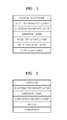
- Figure 1 illustrates a structure of a general organic light-emitting device.
- the general organic light-emitting device includes a substrate, a first electrode (e.g., anode), a hole injection layer (HIL), a hole transport layer (HTL), an emission layer (EML), an electron transport layer (ETL), an electron injection layer (EIL), and a second electrode (e.g., cathode).
- a first electrode e.g., anode
- HIL hole injection layer
- HTL hole transport layer
- EML emission layer
- ETL electron transport layer
- EIL electron injection layer
- cathode e.g., cathode
- the first electrode is formed on the substrate by using a deposition or sputtering method.
- the first electrode may comprise a first electrode material having a high work function.
- the first electrode may be an anode or a cathode.
- the substrate may be a substrate generally used in organic light-emitting devices, and may include, for example, a glass substrate or a transparent plastic substrate, which has excellent mechanical strength, thermal stability, transparency, surface planarity, handling convenience, and water resistance.
- the first electrode material may include materials, such as indium tin oxide (ITO), indium zinc oxide (IZO), tin oxide (SnO 2 ), zinc oxide (ZnO), aluminum (Al), silver (Ag), and magnesium (Mg), which have excellent conductivity, and may form a transparent or reflective electrode.
- ITO indium tin oxide
- IZO indium zinc oxide
- SnO 2 tin oxide
- ZnO zinc oxide
- Al aluminum
- Mg magnesium
- a HIL may be formed on the first electrode by using spin coating, casting, Langmuir Blodgett (LB) deposition, or the like.
- coating conditions may vary according to the compound that is used to form the HIL, and the structure and thermal properties of the HIL to be formed.
- the coating conditions may include a coating speed of about 1000 rpm to about 5000 rpm, and a thermal treatment temperature of about 80°C to about 250°C, wherein the thermal treatment is for removing a solvent after coating.
- the HIL may comprise any material that is commonly used to form a HIL.
- the material that can be used to form the HIL may include a phthalocyanine compound such as copperphthalocyanine; 4,4',4"-tris (3-methylphenylphenylamino) triphenylamine (m-MTDATA); N,N'-di(1-naphthyl)-N,N'-diphenylbenzidine (NPB); TDATA; 2-TNATA; polyaniline/dodecylbenzenesulfonic acid (Pani/DBSA); poly(3,4-ethylenedioxythiophene)/poly(4-styrenesulfonate) (PEDOT/PSS); polyaniline/camphor sulfonic acid (Pani/CSA); and polyaniline/poly(4-styrenesulfonate (PANI/PSS), but are not limited thereto.
- a phthalocyanine compound such as copperphthalocyanine; 4,4
- the HIL may have a thickness of about 100 ⁇ to about 10000 ⁇ .
- the HIL may have a thickness of about 100 ⁇ to about 1000 ⁇ .
- the HIL may have excellent hole injection characteristics without an increase in a driving voltage.
- a HTL may be formed on the HIL by using spin coating, casting, Langmuir-Blodgett (LB) deposition, or the like.
- LB Langmuir-Blodgett
- the conditions for deposition and coating are similar to those for the formation of the HIL, though the conditions for the deposition and coating may vary according to the material that is used to form the HTL.
- the HTL material may include the polymer of Formula 1 described above.
- a well-known HTL material may be used together with the polymer of Formula 1.
- the HTL materials may include, but are not limited to, carbazol derivatives such as N-phenylcarbazol or polyvinylcarbazol, and amine derivatives having an aromatic condensed ring, such as NPB; N,N'-bis(3-methylphenyl)- N,N'-diphenyl-[1,1-biphenyl]-4,4'-diamine (TPD); or N,N'-di(naphthalene-1-yl).
- carbazol derivatives such as N-phenylcarbazol or polyvinylcarbazol
- amine derivatives having an aromatic condensed ring such as NPB; N,N'-bis(3-methylphenyl)- N,N'-diphenyl-[1,1-biphenyl]-4,4'-diamine (TPD); or N,
- the HTL may have a thickness of about 50 ⁇ to about 1000 ⁇ .
- the HTL may have a thickness of 100 ⁇ to about 600 ⁇ .
- the HTL may have excellent hole transport characteristics without a substantial increase in a driving voltage.
- an EML may be formed on the HTL by using spin coating, casting, LB, or the like.
- the conditions for deposition are similar to those for the formation of the HIL, although the conditions for deposition may vary according to the material that is used to form the EML.
- the EML may include the polymer represented by Formula 1 described above.
- the polymer represented by Formula 1 may be used as a host or a dopant in a blue EML.
- the EML may be formed using a variety of well-known light-emitting materials in addition to the polymer represented by Formula 1, and may also be formed using a well-known host and a dopant.
- Dopants used to form the EML may include either a fluorescent dopant or a phosphorescent dopant, which are widely known in the art.
- Examples of the host may include, but are not limited to, Alq 3 , 4,4'-N,N'-dicarbazole-biphenyl (CPB), 9,10-di(naphthalene-2-yl)anthracene (ADN), and distyrylarylene (DSA).
- CNB 4,4'-N,N'-dicarbazole-biphenyl
- ADN 9,10-di(naphthalene-2-yl)anthracene
- DSA distyrylarylene
- red dopants may include, but are not limited to, platinum(II) octaethylporphyrin (PtOEP), Ir(piq) 3' Btp 2 Ir(acac), and DCJTB.
- green dopants may include, but are not limited to, Ir(ppy) 3 (where "ppy” denotes phenylpyridine), Ir(ppy) 2 (acac), Ir(mpyp) 3 , and C545T.
- blue dopants may include, but are not limited to, F 2 Irpic, (F 2 ppy) 2 Ir(tmd), Ir(dfppz) 3 , ter-fluorene, 4,4'-bis(4-diphenylaminostyryl)biphenyl (DPAVBi), and 2,5,8,11-tetra-t-butyl pherylene (TBP).
- the amount of the dopant may be from about 0.1 to about 20 parts by weight.
- the amount of the dopant may be from about 0.5 to about 12 parts by weight, based on 100 parts by weight of the EML material, which is equivalent to the total weight of the host and the dopant.
- concentration quenching may be substantially prevented.
- the EML may have a thickness of about 100 ⁇ to about 1000 ⁇ .
- the EML may have a thickness of about 200 ⁇ to about 600 ⁇ .
- the EML may have excellent light-emitting characteristics without a substantial increase in a driving voltage.
- a hole blocking layer (HBL, not shown in Figure 1 ) may be formed on the EML in order to prevent diffusion of triplet excitons or holes into the ETL.
- HBL may comprise any material that is commonly used to form a HBL. Examples of such HBL materials may include, but are not limited to, oxadiazole derivatives, triazole derivatives, phenathroline derivatives, BAlq, and BCP.
- the HBL may have a thickness of about 50 ⁇ to about 1,000 ⁇ .
- the HBL may have a thickness of about 100 ⁇ to about 300 ⁇ .
- the thickness of the HBL is less than about 50 ⁇ , hole blocking characteristics may be degraded.
- the thickness of the HBL is greater than about 1000 ⁇ , the driving voltage of the organic light emitting device may be increased.
- an ETL may be formed on the HBL or EML by using spin coating, casting, or the like.
- the deposition or coating conditions may be similar to those used to form the HIL, though the deposition and coating conditions may vary according to the material that is used to form the ETL.
- the ETL material may include the heterocyclic compound of Formula 1 described above.
- the ETL may comprise any material that is widely known in the art.
- Examples of the ETL material may include, but are not limited to, quinoline derivatives, such as tris(8-quinolinolate)aluminum (Alq 3 ), TAZ, and BAIq.
- the ETL may have a thickness of about 100 ⁇ to about 1000 ⁇ .
- the ETL may have a thickness of about 100 ⁇ to about 500 ⁇ .
- the ETL may have excellent electron transport characteristics without a substantial increase in a driving voltage.
- an EIL which facilitates injection of electrons from the cathode, may be formed on the ETL.
- An EIL material may include the heterocyclic compound of Formula 1 described above.
- well-known EIL materials such as LiF, NaCl, CsF, Li 2 O, or BaO, may be used to form the EIL.
- the deposition or coating conditions for forming the EIL may be similar to those applied to form the HIL, although the deposition and coating conditions may vary according to the material that is used to form the EIL.
- the EIL may have a thickness of about 1 ⁇ to about 100 ⁇ .
- the EIL may have a thickness of about 5 ⁇ to about 90 ⁇ .
- the EIL may have excellent electron injection characteristics without a substantial increase in a driving voltage.
- the second electrode may be formed on the EIL using, for example, vacuum deposition, sputtering, or the like.
- the second electrode may constitute a cathode or an anode.
- a second electrode material may include a metal, an alloy, an electrically conductive compound, or mixtures thereof, all of which have a low work function. Examples of such materials may include, but are not limited to, lithium (Li), magnesium (Mg), aluminum (Al), aluminum-lithium (Al-Li), calcium (Ca), magnesium-indium(Mg-In), and magnesium-silver (Mg-Ag).
- a transparent cathode comprising a transparent material such as ITO or IZO may be used as the second electrode.
- the organic light-emitting device may be included in various types of flat panel display devices, such as in a passive matrix organic light-emitting display device or in an active matrix organic light-emitting display device.
- the first electrode on the substrate may function as a pixel electrode electrically connected to a source electrode or a drain electrode of the thin-film transistor.
- the organic light-emitting device may also be included in a flat panel display device having a double-sided screen.
- reaction mixture was cooled to room temperature and then extracted by adding 200 mL of distilled water in a volume ratio of xylene to water of 1:1.
- the organic phase was collected, dried using MgSO 4 and then concentrated.
- the concentrated product was refined using silica gel column chromatography in which a mixture of toluene and hexane in a volume ratio of 1:2 was used as an eluant. Then, the resulting effluent was concentrated and dried to obtain 15.2 g of Compound with a yield of 71%.
- a phenothiazine monomer d may be also manufactured as in the method above.
- the reaction mixture was cooled to room temperature and then extracted by adding 200 mL of distilled water in a volume ratio of xylene to water of 1:1.
- the organic phase was collected, dried using MgSO 4 , and then concentrated.
- the concentrated product was refined using silica gel column chromatography in which toluene was used as an eluant.
- the resulting effluent was dissolved in toluene and precipitated in 4 L of MeOH.
- the precipitated resultant was washed, dried under reduced pressure, and precipitated in toluene/MeOH three times. Accordingly, 8.8 g of the polymer represented by Formula 3 was obtained in the form of a light yellow solid.
- the resulting polymer was analyzed using gas permeation chromatography (GPC). As a result, the polymer had a weight-average molecular weight (Mw) of 38,000, and a molecular weight dispersion of 2.8.
- Mw weight-average molecular weight
- the reaction mixture was cooled to room temperature and then extracted by adding 200 mL of distilled water in a volume ratio of xylene to water of 1:1.
- the organic phase was collected, dried using MgSO 4 and then concentrated.
- the concentrated product was refined using silica gel column chromatography in which toluene was used as an eluant.
- the resulting effluent was precipitated by adding 800 mL of ethanol.
- An organic material obtained as above was condensed, dissolved in 100 mL of THF, and precipitated in 2 L of MeOH.
- the precipitated resultant was washed, dried under reduced pressure, and precipitated in toluene/MeOH three times. Accordingly, 3.1 g of the polymer ) represented by Formula 4 was obtained in the form of a light yellow solid.
- the resulting polymer was analyzed using gas permeation chromatography (GPC). As a result, the polymer had a weight-average molecular weight (Mw) of 40,000, and a molecular weight dispersion of 3.2.
- Mw weight-average molecular weight
- An organic light emitting device was manufactured as in Figure 3 .
- a 15 ⁇ /cm 2 (1,200 ⁇ ) ITO glass substrate (available from Corning Co.) was cut to a size of 50 mm x 50 mm x 0.5 mm, ultrasonically washed with isopropyl alcohol for 5 minutes and then with pure water for 5 minutes, and washed again with UV ozone for 20 minutes. Then, CH8000 from H.C.Stark Co. as a conductive buffer layer was coated to a thickness of about 600 ⁇ on the ITO film and then baked for about 20 minutes at 200°C.
- LiF having a thickness of about 80 ⁇ and A1 having a thickness of about 3000 ⁇ were sequentially vacuum deposited on the ETL to form a LiF/A1 electrode.
- a crystal sensor was used in regulating a thickness of the layer and growing speed of the layer during deposition.
- An organic light emitting device was manufactured in the same manner as in Example 1, except that the polymer represented by Formula 4 was used as a HTL.
- An organic light emitting device was manufactured as in Figure 2 .
- the organic light emitting device was manufactured in the same manner as in Example 1, except that the HTL was not formed.
- An organic light emitting device was manufactured in the same manner as in Example 1, except that the polymer represented by Formula 10 was used as a HTL.
- an interlayer is not disposed on the buffer layer in the organic light emitting device of Comparative Example 1.
- the organic light emitting device of Comparative Example 1 has low luminescent efficiency and reduced lifetime compared with the organic light emitting devices of Examples 1 and 2 and Comparative Example 2 which have an interlayer. Accordingly, the interlayer is required.
- the polymer compound (Example 1) including an arylamine group in phenoxazine has excellent hole transport capability and high stability, compared with the phenoxazine polymer (Comparative Example 2) without an arylamine group, and thus have excellent efficiency and long lifetime.
- Phenoxazine or phenothiazine used herein has great charge mobility and energy gap and thus may improve performance of the organic light-emitting device as a material for forming the blue EML, HIL, HTL, ETL, or EIL.
- aryl amine is included at both sides of the phenoxazine monomer so as to improve hole mobility and thus is excellent as a material for forming an HTL.
Landscapes
- Chemical & Material Sciences (AREA)
- Organic Chemistry (AREA)
- Health & Medical Sciences (AREA)
- Chemical Kinetics & Catalysis (AREA)
- Medicinal Chemistry (AREA)
- Polymers & Plastics (AREA)
- Engineering & Computer Science (AREA)
- Materials Engineering (AREA)
- Physics & Mathematics (AREA)
- Optics & Photonics (AREA)
- Electroluminescent Light Sources (AREA)
- Macromolecular Compounds Obtained By Forming Nitrogen-Containing Linkages In General (AREA)
Abstract

Description
- The present invention relates to a polymer compound and an organic light-emitting device including the same.
- Organic electroluminescent devices may be made light-weight and thin, realize various colors, have a fast switching speed, and achieve high brightness at a low driving voltage. As a result, outstanding achievements have been accomplished in a short period of time with regard to the performances of such devices such as balanced charge injection by a multi-layered structure, improvements in color adjustment through doping and quantum efficiency, and development of new electrode materials using alloys.
- Light is emitted when electricity is applied to poly(1,4-phenylenevinylene (PPV)), an example of π-conjugated polymer. The π-conjugated polymer has a chemical structure in which single bonds (or σ-bond) or double bonds (or π-bond) alternately exist and thus has π-electrons that are not lateralized and may freely move along bond chains. According to such a characteristic of a semiconductor, the π-conjugated polymers may be applied to an emission layer of an organic electroluminescent device, and light in the entire visible light area that corresponds to the HOMO-LUMO band-gap may be easily obtained by a molecular design. Also, a thin film may be simply formed by spin coating or printing so that a process of manufacturing the devices is simple and cost thereof is low. Also, the π-conjugated polymers have high glass transition temperature, and thus, a thin film having excellent mechanical properties may be provided.
- However, in organic electroluminescent devices including polymers, problems such as deterioration of color purity, high driving voltage, and low efficiency may occur, and studies to overcome such problems have been widely conducted. For example, improvements in the electroluminescent properties by copolymerizing polymers containing fluorine or blending polymers containing fluorine have been proposed. However, the degree of improvement is still insufficient. Therefore, the development of polymer materials having excellent properties is required.
- According to a first aspect of the present invention, there is provided a polymer represented by Formula 1 below:

- n is a real number in the range of about 0.01 to about 0.99,
- X is O or S,
- R1 is H, a substituted or unsubstituted linear or branched C1-C20 alkyl group, a substituted or unsubstituted cyclic C3-C20 alkyl group, or a substituted or unsubstituted C6-C14 aromatic group, wherein the aromatic group may be substituted with a substituted or unsubstituted C1-C20 alkyl group or a substituted or unsubstituted C1-C20alkoxy group,
- R2 and R3 are each independently a substituted or unsubstituted C6-C26 aromatic group or a heteroaromatic group, wherein the aromatic group or the heteroaromatic group may be substituted with a substituted or unsubstituted C1-C20 alkyl group or a substituted or unsubstituted C1-C20 alkoxy group, and
- Ar is a linear or branched substituted or unsubstituted C1-C20 alkyl group, a substituted or unsubstituted C6-C26 aromatic group or a heteroaromatic group , wherein the aromatic group or the heteroaromatic group is substituted with a substituted or unsubstituted C1-C20 alkyl group or a substituted or unsubstituted C1-C20 alkoxy group.
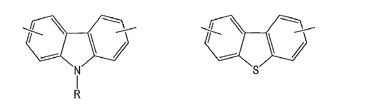
- Ar may be one of the groups represented by Formula 2 below:




- R1, R2, and R3 may be each independently a phenyl group.
- The weight-average molecular weight of the polymer may be in the range of about 10,000 to about 300,000.
- The polymer may be represented by one of Formulae 3 through 9 below:


- The molecular weight dispersion of the polymer may be in the range of about 1.5 to about 4.
- The polymer may be used in an organic light-emitting device.
- In an embodiment, the polymer is represented by formula 3 below:

- In an embodiment, the polymer is represented by formula 4 below:

- According to a second aspect of the present invention, there is provided an organic light-emitting device including: a first electrode; a second electrode; and an organic layer interposed between the first electrode and the second electrode, wherein the organic layer comprises at least one layer comprising the polymer above.
- The organic layer may include a hole transport layer.
- The organic layer may include an emission layer.
- According to a third aspect of the present invention, there is provided use of a polymer according to the invention in its first aspect in an organic light-emitting device.
- A more complete appreciation of the present invention, and many of the attendant advantages thereof, will be readily apparent as the same becomes better understood by reference to the following detailed description when considered in conjunction with the accompanying drawings, wherein:
-
Figure 1 is a cross-sectional view of a general organic light-emitting device; -
Figure 2 is a cross-sectional view of an organic light-emitting device of Comparative Example 1; and -
Figure 3 is a cross-sectional view of an organic light-emitting device of Example 1, in accordance with the invention. - The present invention will now be described more fully with reference to the accompanying drawings, in which exemplary embodiments of the invention are shown.
- A polymer according to the invention may be represented by Formula 1 below:

- X is O or S,
- R1 is H, a substituted or unsubstituted linear or branched C1-C20 alkyl group, a substituted or unsubstituted cyclic C3-C20 alkyl group, or a substituted or unsubstituted C6-C14 aromatic group, wherein the aromatic group may be substituted with a substituted or unsubstituted C1-C20 alkyl group or a substituted or unsubstituted C1-C20alkoxy group,
- R2 and R3 are each independently a substituted or unsubstituted C6-C26 aromatic group or a heteroaromatic group, wherein the aromatic group or the heteroaromatic group may be substituted with a substituted or unsubstituted C1-C20 alkyl group or a substituted or unsubstituted C1-C20 alkoxy group.
- Substituents R1, R2, and R3 in the polymer compound of Formula 1 will now be described.
- In Formula 1, R2 and R3 may be the same as each other or R1, R2, and R3 may be the same as each other. Hereinafter, substituents described with reference to Formula 1 will now be defined.
- In Formula 1, examples of the linear or branched C1-C20 alkyl group may include, but are not limited to, a methyl group, an ethyl group, a propyl group, an isobutyl group, a sec-butyl group, a pentyl group, an iso-amyl group, a hexyl group, a heptyl group, an octyl group, a nonyl group, or dodecyl group. At least one hydrogen atom in the alkyl group may be substituted with a deuterium atom, a tritium atom, a halogen atom, a hydroxyl group, a nitro group, a cyano group, an amino group, an amidino group, hydrazine, hydrazone, a carboxyl group or a salt thereof, a sulfonic acid group or a salt thereof, a phosphoric acid or a salt thereof, a C1-C10 alkyl group, a C1-C10 alkoxy group, a C2-C10 alkenyl group, a C2-C10 alkynyl group, a C6-C16 aryl group, and a C4-C16 heteroaryl group.
- In Formula 1, at least one hydrogen atom in the cyclic C3-C20 alkyl group may be substituted with a deuterium atom, a tritium atom, a halogen atom, a hydroxyl group, a nitro group, a cyano group, an amino group, an amidino group, hydrazine, hydrazone, a carboxyl group or a salt thereof, a sulfonic acid group or a salt thereof, a phosphoric acid or a salt thereof, a C1-C10 alkyl group, a C1-C10 alkoxy group, a C2-C10 alkenyl group, a C2-C10 alkynyl group, a C6-C16 aryl group, and a C4-C16 heteroaryl group.
- In Formula 1, Ar may be a linear or branched substituted or unsubstituted C1-C20 alkyl group, or a substituted or unsubstituted C6-C26 aromatic group or a heteroaromatic group, wherein the aromatic group or the heteroaromatic group may be substituted with a C1-C20 alkyl group or a substituted or unsubstituted C1-C20 alkoxy group.
- In Formula 1, the aromatic group refers to a carbocyclic aromatic system containing at least one ring. When the carbocyclic aromatic system includes at least two rings, the at least two rings may be fused to each other or linked to each other by a single bond. The term 'aromatic' includes an aromatic system, such as, for example, phenyl, naphthyl, or anthracenyl. At least one hydrogen atom in the aromatic group may be substituted with a deuterium atom, a tritium atom, a halogen atom, a hydroxyl group, a nitro group, a cyano group, an amino group, an amidino group, hydrazine, hydrazone, a carboxyl group or a salt thereof, a sulfonic acid group or a salt thereof, a phosphoric acid or a salt thereof, a C1-C10 alkyl group, a C1-C10 alkoxy group, a C2-C10 alkenyl group, a C2-C10 alkynyl group, a C6-C16 aryl group, and a C4-C16 heteroaryl group.
- Examples of the aromatic group include, but are not limited to, a phenyl group, a C1-C10 alkylphenyl group (for example, ethylphenyl group), a halophenyl group (for example, o-, m-, and p-fluorophenyl group, dichlorophenyl group), a cyanophenyl group, dicyanophenyl group, a trifluoromethoxyphenyl group, a biphenyl group, a halobiphenyl group, a cyanobiphenyl group, a C1-C10 alkyl biphenyl group, a C1-C10 alkoxybiphenyl group, a O-, m-, and p-toryl group, an O-, m-, and p-cumenyl group, a mesityl group, a phenoxyphenyl group, a (α,α-dimethylbenzene)phenyl group, a (N,N'-dimethyl)aminophenyl group, a (N,N'-diphenyl)aminophenyl group, a pentalenyl group, an indenyl group, a naphthyl group, a halonaphthyl group (for example, fluoronaphthyl group), a C1-C10 alkylnaphthyl group (for example, methylnaphthyl group), a C1-C10 alkoxynaphthyl group (for example, methoxynaphthyl group), a cyanonaphthyl group, an anthracenyl group, an azulenyl group, a heptalenyl group, an acenaphthylenyl group, a phenalenyl group, a fluorenyl group, an anthraquinolyl group, a methylanthryl group, a phenanthryl group, a triphenylene group, a pyrenyl group, a chrycenyl group, an ethyl-chrysenyl group, a picenyl group, a perylenyl group, a chloroperylenyl group, a pentaphenyl group, a pentacenyl group, a tetraphenylenyl group, a hexaphenyl group, a hexacenyl group, a rubicenyl group, a coronelyl group, a trinaphthylenyl group, a heptaphenyl group, a heptacenyl group, a pyranthrenyl group, and an ovalenyl group.
- In Formula 1, the hetero aromatic group includes one, two or three hetero atoms selected from N, O, P and S. At least two rings may be fused to each other or linked to each other by a single bond. Examples of the hetero aromatic group may include a pyrazolyl group, an imidazolyl group, an oxyzolyl group, a thiazolyl group, a triazolyl group, a tetrazolyl group, an oxadiazolyl group, a pyridinyl group, a pyridazinyl group, a pyrimidinyl group, a triazinyl group, a carbazolyl group, an indolyl group, a quinolinyl group, an isoquinolinyl group, and the like. At least one hydrogen atom in the hetero aromatic group may be substituted with a deuterium atom, a tritium atom, a halogen atom, a hydroxyl group, a nitro group, a cyano group, an amino group, an amidino group, hydrazine, hydrazone, a carboxyl group or a salt thereof, a sulfonic acid group or a salt thereof, a phosphoric acid or a salt thereof, a C1-C10 alkyl group, a C1-C10 alkoxy group, a C2-C10 alkenyl group, a C2-C10 alkynyl group, a C6-C16 aryl group, and a C4-C16 heteroaryl group.
- The alkoxy group used herein is a group having a structure of —OA, wherein A is a linear or branched C1-C20 alkyl group as described above. Examples thereof may include, but are not limited to, a methoxy group, an ethoxy group, a propoxy group, an isopropyloxy group, a butoxy group, and a pentoxy group. At least one hydrogen atom of the alkoxy group may be substituted with a deuterium atom, a tritium atom, a halogen atom, a hydroxyl group, a nitro group, a cyano group, an amino group, an amidino group, hydrazine, hydrazone, a carboxyl group or a salt thereof, a sulfonic acid group or a salt thereof, a phosphoric acid or a salt thereof, a C1-C10 alkyl group, a C1-C10 alkoxy group, a C2-C10 alkenyl group, a C2-C10 alkynyl group, a C6-C16 aryl group, and a C4-C16 heteroaryl group.
- Ar may be one of the groups represented by Formula 2 below:


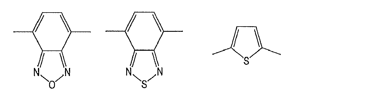


- In Formula 2, m is a positive number from about 1 to about 4 and R is a C1-C20 alkyl group.
- According to an embodiment, R1, R2, and R3 may each independently be a phenyl group. The weight-average molecular weight of the polymer may be from about 10,000 to about 300,000. The molecular weight dispersion of the polymer may be from about 1.5 to about 4.
- When the weight-average molecular weight and the molecular weight dispersion are within the above range, processability is excellent, thereby facilitating an operation and resulting in excellent performance.
- In an embodiment, the polymer compound is represented by one of Formulae 3 through 9 below:


- The polymer may include an amine group directly connected to phenoxazine in a main chain. When the polymer includes an amine group directly connected to phenoxazine in a main chain, the polymer is stable and has excellent hole transport capability due to the amine group. Accordingly, the polymer may be efficiently used in an organic light-emitting device.
- An organic light-emitting device according to an aspect of the invention includes a first electrode, a second electrode, and an organic layer disposed between the first electrode and the second electrode, the organic layer including the polymer of Formula 1 described above.
- The organic layer including the polymer of Formula 1 may be a hole transport layer or an emission layer.
- The first electrode may be an anode and the second electrode may be a cathode, but the reverse is also possible.
- Hereinafter, a method of manufacturing a general organic light-emitting device of
Figure 1 will be described.Figure 1 illustrates a structure of a general organic light-emitting device. Referring toFigure 1 , the general organic light-emitting device includes a substrate, a first electrode (e.g., anode), a hole injection layer (HIL), a hole transport layer (HTL), an emission layer (EML), an electron transport layer (ETL), an electron injection layer (EIL), and a second electrode (e.g., cathode). - First, the first electrode is formed on the substrate by using a deposition or sputtering method. The first electrode may comprise a first electrode material having a high work function. The first electrode may be an anode or a cathode. The substrate may be a substrate generally used in organic light-emitting devices, and may include, for example, a glass substrate or a transparent plastic substrate, which has excellent mechanical strength, thermal stability, transparency, surface planarity, handling convenience, and water resistance. Examples of the first electrode material may include materials, such as indium tin oxide (ITO), indium zinc oxide (IZO), tin oxide (SnO2), zinc oxide (ZnO), aluminum (Al), silver (Ag), and magnesium (Mg), which have excellent conductivity, and may form a transparent or reflective electrode.
- Then, a HIL may be formed on the first electrode by using spin coating, casting, Langmuir Blodgett (LB) deposition, or the like.
- When the HIL is formed using spin coating, coating conditions may vary according to the compound that is used to form the HIL, and the structure and thermal properties of the HIL to be formed. For example, the coating conditions may include a coating speed of about 1000 rpm to about 5000 rpm, and a thermal treatment temperature of about 80°C to about 250°C, wherein the thermal treatment is for removing a solvent after coating.
- The HIL may comprise any material that is commonly used to form a HIL. Examples of the material that can be used to form the HIL may include a phthalocyanine compound such as copperphthalocyanine; 4,4',4"-tris (3-methylphenylphenylamino) triphenylamine (m-MTDATA); N,N'-di(1-naphthyl)-N,N'-diphenylbenzidine (NPB); TDATA; 2-TNATA; polyaniline/dodecylbenzenesulfonic acid (Pani/DBSA); poly(3,4-ethylenedioxythiophene)/poly(4-styrenesulfonate) (PEDOT/PSS); polyaniline/camphor sulfonic acid (Pani/CSA); and polyaniline/poly(4-styrenesulfonate (PANI/PSS), but are not limited thereto.


- The HIL may have a thickness of about 100 Å to about 10000 Å. The HIL may have a thickness of about 100 Å to about 1000 Å. When the thickness of the HIL is within the above range, the HIL may have excellent hole injection characteristics without an increase in a driving voltage.
- Then a HTL may be formed on the HIL by using spin coating, casting, Langmuir-Blodgett (LB) deposition, or the like. When the HTL is formed using spin coating, the conditions for deposition and coating are similar to those for the formation of the HIL, though the conditions for the deposition and coating may vary according to the material that is used to form the HTL.
- The HTL material may include the polymer of Formula 1 described above. Alternatively, a well-known HTL material may be used together with the polymer of Formula 1. Examples of the HTL materials may include, but are not limited to, carbazol derivatives such as N-phenylcarbazol or polyvinylcarbazol, and amine derivatives having an aromatic condensed ring, such as NPB; N,N'-bis(3-methylphenyl)- N,N'-diphenyl-[1,1-biphenyl]-4,4'-diamine (TPD); or N,N'-di(naphthalene-1-yl).


- The HTL may have a thickness of about 50 Å to about 1000 Å. The HTL may have a thickness of 100 Å to about 600 Å. When the thickness of the HTL is within the above range, the HTL may have excellent hole transport characteristics without a substantial increase in a driving voltage.
- Then, an EML may be formed on the HTL by using spin coating, casting, LB, or the like. When the EML is formed using spin coating, the conditions for deposition are similar to those for the formation of the HIL, although the conditions for deposition may vary according to the material that is used to form the EML.
- The EML may include the polymer represented by Formula 1 described above. For example, the polymer represented by Formula 1 may be used as a host or a dopant in a blue EML. The EML may be formed using a variety of well-known light-emitting materials in addition to the polymer represented by Formula 1, and may also be formed using a well-known host and a dopant. Dopants used to form the EML may include either a fluorescent dopant or a phosphorescent dopant, which are widely known in the art.
- Examples of the host may include, but are not limited to, Alq3, 4,4'-N,N'-dicarbazole-biphenyl (CPB), 9,10-di(naphthalene-2-yl)anthracene (ADN), and distyrylarylene (DSA).
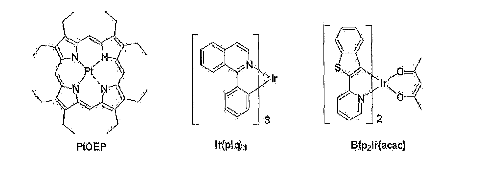
- Examples of well-known red dopants may include, but are not limited to, platinum(II) octaethylporphyrin (PtOEP), Ir(piq)3' Btp2Ir(acac), and DCJTB.
- Examples of well-known green dopants may include, but are not limited to, Ir(ppy)3 (where "ppy" denotes phenylpyridine), Ir(ppy)2(acac), Ir(mpyp)3, and C545T.


- Examples of well-known blue dopants may include, but are not limited to, F2Irpic, (F2ppy)2Ir(tmd), Ir(dfppz)3, ter-fluorene, 4,4'-bis(4-diphenylaminostyryl)biphenyl (DPAVBi), and 2,5,8,11-tetra-t-butyl pherylene (TBP).

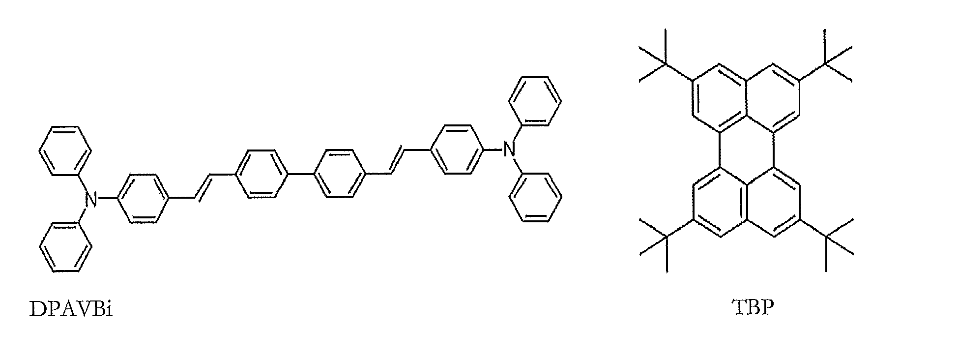
- The amount of the dopant may be from about 0.1 to about 20 parts by weight. The amount of the dopant may be from about 0.5 to about 12 parts by weight, based on 100 parts by weight of the EML material, which is equivalent to the total weight of the host and the dopant. When the amount of the dopant is within the above range, concentration quenching may be substantially prevented.
- The EML may have a thickness of about 100 Å to about 1000 Å. The EML may have a thickness of about 200 Å to about 600 Å. When the thickness of the EML is within the above range, the EML may have excellent light-emitting characteristics without a substantial increase in a driving voltage.
- When the EML includes a phosphorescent dopant, a hole blocking layer (HBL, not shown in
Figure 1 ) may be formed on the EML in order to prevent diffusion of triplet excitons or holes into the ETL. In this case, the HBL may comprise any material that is commonly used to form a HBL. Examples of such HBL materials may include, but are not limited to, oxadiazole derivatives, triazole derivatives, phenathroline derivatives, BAlq, and BCP. - The HBL may have a thickness of about 50 Å to about 1,000 Å. The HBL may have a thickness of about 100 Å to about 300 Å. When the thickness of the HBL is less than about 50 Å, hole blocking characteristics may be degraded. On the other hand, when the thickness of the HBL is greater than about 1000 Å, the driving voltage of the organic light emitting device may be increased.
- Then an ETL may be formed on the HBL or EML by using spin coating, casting, or the like. When the ETL is formed using spin coating, the deposition or coating conditions may be similar to those used to form the HIL, though the deposition and coating conditions may vary according to the material that is used to form the ETL.
- The ETL material may include the heterocyclic compound of Formula 1 described above. Alternatively, the ETL may comprise any material that is widely known in the art. Examples of the ETL material may include, but are not limited to, quinoline derivatives, such as tris(8-quinolinolate)aluminum (Alq3), TAZ, and BAIq.

- The ETL may have a thickness of about 100 Å to about 1000 Å. The ETL may have a thickness of about 100 Å to about 500 Å. When the ETL has a thickness within the above range, the ETL may have excellent electron transport characteristics without a substantial increase in a driving voltage.
- In addition, an EIL, which facilitates injection of electrons from the cathode, may be formed on the ETL.
- An EIL material may include the heterocyclic compound of Formula 1 described above. Alternatively, well-known EIL materials, such as LiF, NaCl, CsF, Li2O, or BaO, may be used to form the EIL. The deposition or coating conditions for forming the EIL may be similar to those applied to form the HIL, although the deposition and coating conditions may vary according to the material that is used to form the EIL.
- The EIL may have a thickness of about 1 Å to about 100 Å. The EIL may have a thickness of about 5 Å to about 90 Å. When the EIL has a thickness within the above range, the EIL may have excellent electron injection characteristics without a substantial increase in a driving voltage.
- Finally, the second electrode may be formed on the EIL using, for example, vacuum deposition, sputtering, or the like. The second electrode may constitute a cathode or an anode. A second electrode material may include a metal, an alloy, an electrically conductive compound, or mixtures thereof, all of which have a low work function. Examples of such materials may include, but are not limited to, lithium (Li), magnesium (Mg), aluminum (Al), aluminum-lithium (Al-Li), calcium (Ca), magnesium-indium(Mg-In), and magnesium-silver (Mg-Ag). In addition, in order to manufacture a top-emission organic light-emitting device, a transparent cathode comprising a transparent material such as ITO or IZO may be used as the second electrode.
- The organic light-emitting device may be included in various types of flat panel display devices, such as in a passive matrix organic light-emitting display device or in an active matrix organic light-emitting display device. In particular, when the organic light-emitting device is included in an active matrix organic light-emitting display device including a thin-film transistor, the first electrode on the substrate may function as a pixel electrode electrically connected to a source electrode or a drain electrode of the thin-film transistor. Moreover, the organic light-emitting device may also be included in a flat panel display device having a double-sided screen.
- Hereinafter, synthesis examples and Examples of the polymers represented by Formulae 3 and 4 will be described. However, the present invention is not limited to the Examples below.
-

- 10 g (54 mmol) of phenoxazine, 7.4 g (77 mmol) of sodium tert-butoxide, 0.61 g (1.1 mmol) of Pd2(dba)3 [(tris(dibenzylidine acetone) dipalladium(0))], and 0.22 g (1.1 mmol) of tri(tert-butyl)phosphine were dissolved in 200 mL of xylene, and then refluxed at 80°C for 12 hours.
- After completion of the reaction, the reaction mixture was cooled to room temperature and then extracted by adding 200 mL of distilled water in a volume ratio of xylene to water of 1:1. The organic phase was collected, dried using MgSO4 and then concentrated. The concentrated product was refined using silica gel column chromatography in which a mixture of toluene and hexane in a volume ratio of 1:2 was used as an eluant. Then, the resulting effluent was concentrated and dried to obtain 15.2 g of Compound with a yield of 71%.
- 15 g (57.8 mmol) of compound a was dissolved in 200 mL of CHCl3 to obtain a dissolved solution and 18.5 g of bromine (Br2) 2 equivalent was slowly added to the dissolved solution while maintaining the dissolved solution at 0 °C. The mixture was stirred for about 40 minutes and the reaction was stopped.
- A small amount of acetone was added to the reaction mixture and then extracted by using water and CHCl3 in a volume ratio of 2:1 after quenching bromine Br. The organic phase was collected, dried using MgSO4, and then concentrated. The concentrated product was reprecipitated in MeOH to obtain 17 g of Compound b with a yield of 70.5 %.
- 17g (41 mmol) of Compound b, 7.6 g (82 mmol) of aniline, 7.4 g (77 mmol) of sodium tert-butoxide, 0.61 g (1.1 mmol) of Pd2(dba)3 [(tris(dibenzylidine acetone) dipalladium(0))], and 0.22 g (1.1 mmol) of tri(tert-butyl)phosphine were dissolved in 200 mL of xylene, and then refluxed at 60°C for 1 hour.
- After completion of the reaction, the reaction mixture was cooled to room temperature and then extracted by adding 200 mL of distilled water in a volume ratio of xylene to water of 1:1. The organic phase was collected, dried using MgSO4, and then concentrated. The concentrated product was refined using silica gel column chromatography in which a mixture of toluene and hexane in a volume ratio of 1:1 was used as an eluant. Then, the resulting effluent was concentrated and dried to obtain 8 g of Compound c with a yield of 44.2%. 1H-NMR (300MHz, CDCl3): 84.08(s, 2H), δ5.87∼7.01 (m, 20H)
- A phenothiazine monomer d may be also manufactured as in the method above.

-

- 8 g (18 mmol) of Compound c, 8.5 g (18 mmol) of 2,7-dibromo spirofluorene, 7.4 g (77 mmol) of sodium tert-butoxide, 0.61 g (1.1 mmol) of Pd2(dba)3 [(tris(dibenzylidine acetone) dipalladium(0))], and 0.22 g (1.1 mmol) of tri(tert-butyl)phosphine were dissolved in 200 mL of xylene, and then refluxed at 80°C for 2 days.
- After completion of the reaction, the reaction mixture was cooled to room temperature and then extracted by adding 200 mL of distilled water in a volume ratio of xylene to water of 1:1. The organic phase was collected, dried using MgSO4, and then concentrated. The concentrated product was refined using silica gel column chromatography in which toluene was used as an eluant. Then, the resulting effluent was dissolved in toluene and precipitated in 4 L of MeOH. The precipitated resultant was washed, dried under reduced pressure, and precipitated in toluene/MeOH three times. Accordingly, 8.8 g of the polymer represented by Formula 3 was obtained in the form of a light yellow solid.
- The resulting polymer was analyzed using gas permeation chromatography (GPC). As a result, the polymer had a weight-average molecular weight (Mw) of 38,000, and a molecular weight dispersion of 2.8.
-

- 5 g (11 mmol) of Compound d, 5.2 g (11 mmol) of 2,7-dibromo spirofluorene, 5.4 g (60 mmol) of sodium tert-butoxide, 0.61 g (1.1 mmol) of Pd2(dba)3 [(tris(dibenzylidine acetone) dipalladium(0))], and 0.22 g (1.1 mmol) of tri(tert-butyl)phosphine were dissolved in 150 mL of ) xylene, and then refluxed at 80°C for 2 days.
- After completion of the reaction, the reaction mixture was cooled to room temperature and then extracted by adding 200 mL of distilled water in a volume ratio of xylene to water of 1:1. The organic phase was collected, dried using MgSO4 and then concentrated. The concentrated product was refined using silica gel column chromatography in which toluene was used as an eluant. The resulting effluent was precipitated by adding 800 mL of ethanol. An organic material obtained as above was condensed, dissolved in 100 mL of THF, and precipitated in 2 L of MeOH. The precipitated resultant was washed, dried under reduced pressure, and precipitated in toluene/MeOH three times. Accordingly, 3.1 g of the polymer ) represented by Formula 4 was obtained in the form of a light yellow solid.
- The resulting polymer was analyzed using gas permeation chromatography (GPC). As a result, the polymer had a weight-average molecular weight (Mw) of 40,000, and a molecular weight dispersion of 3.2.
- An organic light emitting device was manufactured as in
Figure 3 . A 15Ω/cm2 (1,200Å) ITO glass substrate (available from Corning Co.) was cut to a size of 50 mm x 50 mm x 0.5 mm, ultrasonically washed with isopropyl alcohol for 5 minutes and then with pure water for 5 minutes, and washed again with UV ozone for 20 minutes. Then, CH8000 from H.C.Stark Co. as a conductive buffer layer was coated to a thickness of about 600 Å on the ITO film and then baked for about 20 minutes at 200°C. Then, 3 mg of the polymer of Formula 3 manufactured as above was dissolved in 1 ml of toluene to obtain a polymer solution and the polymer solution was filtered by using a 0.2 µm filter before being spin coated. The filtered polymer solution was spin coated on the buffer layer and then baked for about 10 minutes at 200°C, thereby forming a polymer HTL. The formed polymer HTL had a thickness of about 300 Å by adjusting concentration and spin speed of the polymer solution. After the HTL was formed, DSA as a phosphorescent host and 3 % of TBPe as a dopant were used and vacuum deposited, thereby forming an EML having a thickness of about 300 Å. Then, Alq3 was vacuum deposited on the EML to form an ETL having a thickness of about 200 Å. LiF having a thickness of about 80 Å and A1 having a thickness of about 3000 Å were sequentially vacuum deposited on the ETL to form a LiF/A1 electrode. A crystal sensor was used in regulating a thickness of the layer and growing speed of the layer during deposition. - An organic light emitting device was manufactured in the same manner as in Example 1, except that the polymer represented by Formula 4 was used as a HTL.
- An organic light emitting device was manufactured as in
Figure 2 . The organic light emitting device was manufactured in the same manner as in Example 1, except that the HTL was not formed. - An organic light emitting device was manufactured in the same manner as in Example 1, except that the polymer represented by Formula 10 was used as a HTL.

- Current density (mA/cm2), driving voltage (V), brightness (cd/m2), and luminescent efficiency (cd/A) of each of the organic light-emitting devices of the Examples and Comparative Examples were measured by using a PR650 (Spectroscan) Source Measurement Unit and a half lifetime (cd/m2) thereof was also measured (Mc Science Co.). The results are shown in Table 1 below.
[Table 1] Luminescent efficiency (cd/A) half lifetime (cd/m2) Example 1 (Formula 3) 5.15 1500 Example 2 (Formula 4) 4.88 2500 Comparative Example 1 1.86 13 Comparative Example 2 2.50 800 - Referring to Table 1, an interlayer is not disposed on the buffer layer in the organic light emitting device of Comparative Example 1. Thus, the organic light emitting device of Comparative Example 1 has low luminescent efficiency and reduced lifetime compared with the organic light emitting devices of Examples 1 and 2 and Comparative Example 2 which have an interlayer. Accordingly, the interlayer is required.
- The polymer compound (Example 1) including an arylamine group in phenoxazine has excellent hole transport capability and high stability, compared with the phenoxazine polymer (Comparative Example 2) without an arylamine group, and thus have excellent efficiency and long lifetime.
- Phenoxazine or phenothiazine used herein has great charge mobility and energy gap and thus may improve performance of the organic light-emitting device as a material for forming the blue EML, HIL, HTL, ETL, or EIL.
- In particular, aryl amine is included at both sides of the phenoxazine monomer so as to improve hole mobility and thus is excellent as a material for forming an HTL.
- Whilst the present invention has been described in connection with certain exemplary embodiments thereof, it is to be understood that the invention is not limited to the disclosed embodiments, but, on the contrary, is intended to cover various modifications and equivalent arrangements included within the scope of the appended claims.
Claims (13)
- A polymer represented by Formula 1 below:
 n is a real number in the range of about 0.01 to about 0.99,X is O or S,R1 is H, a linear or branched substituted or unsubstituted C1-C20 alkyl group, a substituted or unsubstituted cyclic C3-C20 alkyl group, or a substituted or unsubstituted C6-C14 aromatic group, wherein the aromatic group may be substituted with a substituted or unsubstituted C1-C20 alkyl group or a substituted or unsubstituted C1-C20 alkoxy group,R2 and R3 are each independently a substituted or unsubstituted C6-C26 aromatic group or a heteroaromatic group, wherein the aromatic group or the heteroaromatic group may be substituted with a substituted or unsubstituted C1-C20 alkyl group or a substituted or unsubstituted C1-C20 alkoxy group, andAr is a linear or branched substituted or unsubstituted C1-C20 alkyl group, a substituted or unsubstituted C6-C26 aromatic group or a heteroaromatic group , wherein the aromatic group or the heteroaromatic group may be substituted with a substituted or unsubstituted C1-C20 alkyl group or a substituted or unsubstituted C1-C20 alkoxy group.
 - The polymer of claim 1, wherein Ar is one of the groups represented below:


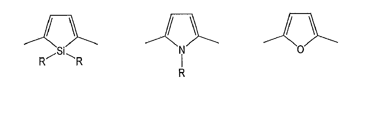


- The polymer of claim 1 or claim 2, wherein R1, R2, and R3 are each independently a phenyl group.
- The polymer of any preceding claim, wherein weight-average molecular weight of the polymer is from 10,000 to 300,000.
- The polymer of any preceding claim, wherein the polymer is represented by one of Formulae 3 through 9 below:
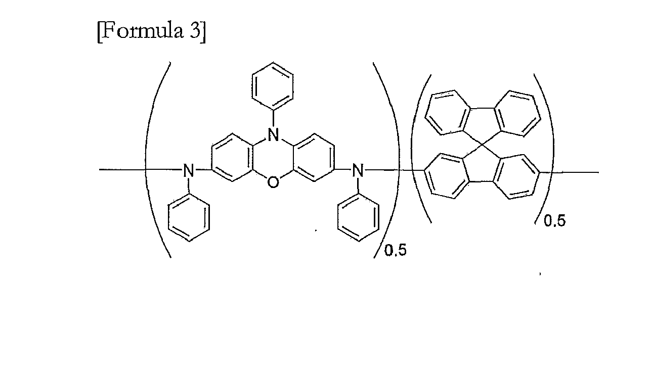
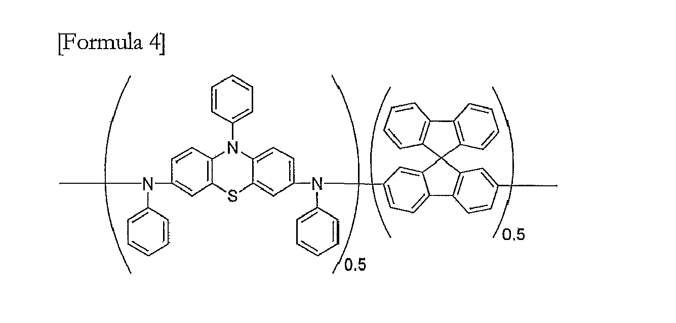


- The polymer of any preceding claim, wherein the molecular weight dispersion of the polymer is from 1.5 to 4.
- The polymer of any preceding claim, for use in an organic light-emitting device.
- The polymer of claim 1, wherein the polymer is represented by Formula 3 below:

- The polymer of claim 1, wherein the polymer is represented by Formula 4 below:

- An organic light-emitting device comprising:a first electrode;a second electrode; andan organic layer interposed between the first electrode and the second electrode,wherein the organic layer comprises at least one layer comprising the polymer of any of claims 1 to 9.
- The organic light-emitting device of claim 10, wherein the organic layer comprises a hole transport layer.
- The organic light-emitting device of claim 10, wherein the organic layer comprises an emission layer.
- Use of a polymer according to any of claims 1 to 9 in an organic light-emitting device.
Applications Claiming Priority (1)
| Application Number | Priority Date | Filing Date | Title |
|---|---|---|---|
| KR1020100030501A KR101174880B1 (en) | 2010-04-02 | 2010-04-02 | Polymer and Organic Light Emitting Device containing the polymer |
Publications (2)
| Publication Number | Publication Date |
|---|---|
| EP2371878A1 true EP2371878A1 (en) | 2011-10-05 |
| EP2371878B1 EP2371878B1 (en) | 2017-03-01 |
Family
ID=44121655
Family Applications (1)
| Application Number | Title | Priority Date | Filing Date |
|---|---|---|---|
| EP11160612.5A Active EP2371878B1 (en) | 2010-04-02 | 2011-03-31 | Polymer compound and organic light-emitting device including the same |
Country Status (5)
| Country | Link |
|---|---|
| US (1) | US8691930B2 (en) |
| EP (1) | EP2371878B1 (en) |
| JP (1) | JP2011219731A (en) |
| KR (1) | KR101174880B1 (en) |
| CN (1) | CN102212193B (en) |
Families Citing this family (4)
| Publication number | Priority date | Publication date | Assignee | Title |
|---|---|---|---|---|
| JP6786858B2 (en) * | 2015-06-19 | 2020-11-18 | 株式会社リコー | Electrochromic compounds and electrochromic compositions |
| WO2017179661A1 (en) * | 2016-04-15 | 2017-10-19 | 日立化成株式会社 | Charge transport material, ink composition using said material, organic electronic element, organic electroluminescent element, display element, lighting device and display device |
| JP6772623B2 (en) * | 2016-07-28 | 2020-10-21 | 日産化学株式会社 | Charge transporting composition |
| KR102193068B1 (en) * | 2019-04-02 | 2020-12-18 | 한국교통대학교 산학협력단 | Hole transfer material for organic electroluminescent device and organic electroluminescent device comprising the same |
Citations (5)
| Publication number | Priority date | Publication date | Assignee | Title |
|---|---|---|---|---|
| US20040127666A1 (en) * | 2002-12-19 | 2004-07-01 | Michael Inbasekaran | Tricyclic arylamine containing polymers and electronic devices therefrom |
| US20070003787A1 (en) * | 2005-06-29 | 2007-01-04 | Lee Tae-Woo | Organic light-emitting device and method of manufacturing the same |
| US20070173633A1 (en) * | 2006-01-26 | 2007-07-26 | Son Jhun-Mo | Electroluminescent polymer and organic electroluminescent device using the same |
| US20070278455A1 (en) * | 2006-06-05 | 2007-12-06 | Sang-Hoon Park | Polymer compound and organic light-emitting device using the same |
| EP2202257A1 (en) * | 2007-10-10 | 2010-06-30 | Sumitomo Chemical Company, Limited | Polymer compound and polymer light-emitting device using the same |
Family Cites Families (4)
| Publication number | Priority date | Publication date | Assignee | Title |
|---|---|---|---|---|
| KR100552683B1 (en) | 2002-06-21 | 2006-02-20 | 삼성에스디아이 주식회사 | Blue electroluminescent polymer and organic-electroluminescent device manufactured by using the same |
| DE102004057073A1 (en) | 2004-11-25 | 2006-06-08 | Basf Ag | Use of phenothiazine S-oxides and -S, S-dioxides as matrix materials for organic light-emitting diodes |
| JP5251043B2 (en) | 2006-09-13 | 2013-07-31 | 住友化学株式会社 | Polymer compound and polymer light emitting device |
| KR101407578B1 (en) | 2007-07-24 | 2014-06-13 | 삼성디스플레이 주식회사 | Phenylphenoxazine or phenylphenothiazine based compounds and organic electroluminescence |
-
2010
- 2010-04-02 KR KR1020100030501A patent/KR101174880B1/en active Active
- 2010-12-27 JP JP2010289799A patent/JP2011219731A/en active Pending
-
2011
- 2011-03-30 US US13/076,160 patent/US8691930B2/en active Active
- 2011-03-31 EP EP11160612.5A patent/EP2371878B1/en active Active
- 2011-04-06 CN CN201110087383.7A patent/CN102212193B/en active Active
Patent Citations (5)
| Publication number | Priority date | Publication date | Assignee | Title |
|---|---|---|---|---|
| US20040127666A1 (en) * | 2002-12-19 | 2004-07-01 | Michael Inbasekaran | Tricyclic arylamine containing polymers and electronic devices therefrom |
| US20070003787A1 (en) * | 2005-06-29 | 2007-01-04 | Lee Tae-Woo | Organic light-emitting device and method of manufacturing the same |
| US20070173633A1 (en) * | 2006-01-26 | 2007-07-26 | Son Jhun-Mo | Electroluminescent polymer and organic electroluminescent device using the same |
| US20070278455A1 (en) * | 2006-06-05 | 2007-12-06 | Sang-Hoon Park | Polymer compound and organic light-emitting device using the same |
| EP2202257A1 (en) * | 2007-10-10 | 2010-06-30 | Sumitomo Chemical Company, Limited | Polymer compound and polymer light-emitting device using the same |
Also Published As
| Publication number | Publication date |
|---|---|
| CN102212193A (en) | 2011-10-12 |
| EP2371878B1 (en) | 2017-03-01 |
| US8691930B2 (en) | 2014-04-08 |
| JP2011219731A (en) | 2011-11-04 |
| CN102212193B (en) | 2014-12-17 |
| US20110240975A1 (en) | 2011-10-06 |
| KR20110111102A (en) | 2011-10-10 |
| KR101174880B1 (en) | 2012-08-17 |
Similar Documents
| Publication | Publication Date | Title |
|---|---|---|
| EP2292603B1 (en) | Organic light-emitting device | |
| EP2289877B1 (en) | Organic light emitting device containing polycyclic heteroaryl compounds | |
| EP2298739B1 (en) | Organic light emitting device containing polycyclic heteroaryl compounds | |
| EP2292618B1 (en) | Organic light emitting device containing polycyclic heteroaryl compounds | |
| EP2292601B1 (en) | Phenanthro[2,3-b]pyrroles and Phenanthro[3,2-b]pyrroles for organic light-emitting devices | |
| EP2407502B1 (en) | Dendrimer and organic light-emitting device using the same | |
| US8384074B2 (en) | Heterocyclic compound and organic light-emitting device including the same | |
| EP2308911A2 (en) | Polymer and organic light-emitting device including the same | |
| EP2392563B1 (en) | Nitrogen containing polycyclic derivatives useful in organic light-emitting devices | |
| US8993128B2 (en) | Heterocyclic compound and organic light-emitting device containing same | |
| EP2298771B1 (en) | Organic Light-Emitting Device | |
| US20090230855A1 (en) | Novel organic compound and organic light emitting device comprising the same | |
| EP2371878B1 (en) | Polymer compound and organic light-emitting device including the same | |
| EP2301920A1 (en) | Organic light emitting device containing naphthoindole derivatives | |
| EP2407501A1 (en) | Dendrimer and organic light-emitting device using the same | |
| US8455866B2 (en) | Heterocyclic compound and organic light-emitting device including the same | |
| KR20090018503A (en) | Oxadiazole derivative compound and organic light emitting device having the same |
Legal Events
| Date | Code | Title | Description |
|---|---|---|---|
| PUAI | Public reference made under article 153(3) epc to a published international application that has entered the european phase |
Free format text: ORIGINAL CODE: 0009012 |
|
| AK | Designated contracting states |
Kind code of ref document: A1 Designated state(s): AL AT BE BG CH CY CZ DE DK EE ES FI FR GB GR HR HU IE IS IT LI LT LU LV MC MK MT NL NO PL PT RO RS SE SI SK SM TR |
|
| AX | Request for extension of the european patent |
Extension state: BA ME |
|
| 17P | Request for examination filed |
Effective date: 20111010 |
|
| RAP1 | Party data changed (applicant data changed or rights of an application transferred) |
Owner name: SAMSUNG DISPLAY CO., LTD. |
|
| RAP1 | Party data changed (applicant data changed or rights of an application transferred) |
Owner name: SAMSUNG DISPLAY CO., LTD. |
|
| GRAP | Despatch of communication of intention to grant a patent |
Free format text: ORIGINAL CODE: EPIDOSNIGR1 |
|
| INTG | Intention to grant announced |
Effective date: 20160906 |
|
| RIN1 | Information on inventor provided before grant (corrected) |
Inventor name: LEE, JAE-YONG Inventor name: KWAK, YOON-HYUN Inventor name: YI, JEOUNG-IN Inventor name: YANG, SEUNG-GAK Inventor name: KIM, HEE-YEON |
|
| STAA | Information on the status of an ep patent application or granted ep patent |
Free format text: STATUS: GRANT OF PATENT IS INTENDED |
|
| GRAS | Grant fee paid |
Free format text: ORIGINAL CODE: EPIDOSNIGR3 |
|
| GRAA | (expected) grant |
Free format text: ORIGINAL CODE: 0009210 |
|
| STAA | Information on the status of an ep patent application or granted ep patent |
Free format text: STATUS: THE PATENT HAS BEEN GRANTED |
|
| AK | Designated contracting states |
Kind code of ref document: B1 Designated state(s): AL AT BE BG CH CY CZ DE DK EE ES FI FR GB GR HR HU IE IS IT LI LT LU LV MC MK MT NL NO PL PT RO RS SE SI SK SM TR |
|
| REG | Reference to a national code |
Ref country code: GB Ref legal event code: FG4D |
|
| REG | Reference to a national code |
Ref country code: CH Ref legal event code: EP Ref country code: AT Ref legal event code: REF Ref document number: 871266 Country of ref document: AT Kind code of ref document: T Effective date: 20170315 |
|
| REG | Reference to a national code |
Ref country code: IE Ref legal event code: FG4D |
|
| REG | Reference to a national code |
Ref country code: FR Ref legal event code: PLFP Year of fee payment: 7 |
|
| REG | Reference to a national code |
Ref country code: DE Ref legal event code: R096 Ref document number: 602011035358 Country of ref document: DE |
|
| REG | Reference to a national code |
Ref country code: NL Ref legal event code: MP Effective date: 20170301 |
|
| REG | Reference to a national code |
Ref country code: LT Ref legal event code: MG4D |
|
| REG | Reference to a national code |
Ref country code: AT Ref legal event code: MK05 Ref document number: 871266 Country of ref document: AT Kind code of ref document: T Effective date: 20170301 |
|
| PG25 | Lapsed in a contracting state [announced via postgrant information from national office to epo] |
Ref country code: FI Free format text: LAPSE BECAUSE OF FAILURE TO SUBMIT A TRANSLATION OF THE DESCRIPTION OR TO PAY THE FEE WITHIN THE PRESCRIBED TIME-LIMIT Effective date: 20170301 Ref country code: GR Free format text: LAPSE BECAUSE OF FAILURE TO SUBMIT A TRANSLATION OF THE DESCRIPTION OR TO PAY THE FEE WITHIN THE PRESCRIBED TIME-LIMIT Effective date: 20170602 Ref country code: NO Free format text: LAPSE BECAUSE OF FAILURE TO SUBMIT A TRANSLATION OF THE DESCRIPTION OR TO PAY THE FEE WITHIN THE PRESCRIBED TIME-LIMIT Effective date: 20170601 Ref country code: LT Free format text: LAPSE BECAUSE OF FAILURE TO SUBMIT A TRANSLATION OF THE DESCRIPTION OR TO PAY THE FEE WITHIN THE PRESCRIBED TIME-LIMIT Effective date: 20170301 Ref country code: HR Free format text: LAPSE BECAUSE OF FAILURE TO SUBMIT A TRANSLATION OF THE DESCRIPTION OR TO PAY THE FEE WITHIN THE PRESCRIBED TIME-LIMIT Effective date: 20170301 |
|
| PG25 | Lapsed in a contracting state [announced via postgrant information from national office to epo] |
Ref country code: ES Free format text: LAPSE BECAUSE OF FAILURE TO SUBMIT A TRANSLATION OF THE DESCRIPTION OR TO PAY THE FEE WITHIN THE PRESCRIBED TIME-LIMIT Effective date: 20170301 Ref country code: LV Free format text: LAPSE BECAUSE OF FAILURE TO SUBMIT A TRANSLATION OF THE DESCRIPTION OR TO PAY THE FEE WITHIN THE PRESCRIBED TIME-LIMIT Effective date: 20170301 Ref country code: AT Free format text: LAPSE BECAUSE OF FAILURE TO SUBMIT A TRANSLATION OF THE DESCRIPTION OR TO PAY THE FEE WITHIN THE PRESCRIBED TIME-LIMIT Effective date: 20170301 Ref country code: BG Free format text: LAPSE BECAUSE OF FAILURE TO SUBMIT A TRANSLATION OF THE DESCRIPTION OR TO PAY THE FEE WITHIN THE PRESCRIBED TIME-LIMIT Effective date: 20170601 Ref country code: SE Free format text: LAPSE BECAUSE OF FAILURE TO SUBMIT A TRANSLATION OF THE DESCRIPTION OR TO PAY THE FEE WITHIN THE PRESCRIBED TIME-LIMIT Effective date: 20170301 Ref country code: RS Free format text: LAPSE BECAUSE OF FAILURE TO SUBMIT A TRANSLATION OF THE DESCRIPTION OR TO PAY THE FEE WITHIN THE PRESCRIBED TIME-LIMIT Effective date: 20170301 |
|
| PG25 | Lapsed in a contracting state [announced via postgrant information from national office to epo] |
Ref country code: NL Free format text: LAPSE BECAUSE OF FAILURE TO SUBMIT A TRANSLATION OF THE DESCRIPTION OR TO PAY THE FEE WITHIN THE PRESCRIBED TIME-LIMIT Effective date: 20170301 |
|
| PG25 | Lapsed in a contracting state [announced via postgrant information from national office to epo] |
Ref country code: RO Free format text: LAPSE BECAUSE OF FAILURE TO SUBMIT A TRANSLATION OF THE DESCRIPTION OR TO PAY THE FEE WITHIN THE PRESCRIBED TIME-LIMIT Effective date: 20170301 Ref country code: CZ Free format text: LAPSE BECAUSE OF FAILURE TO SUBMIT A TRANSLATION OF THE DESCRIPTION OR TO PAY THE FEE WITHIN THE PRESCRIBED TIME-LIMIT Effective date: 20170301 Ref country code: IT Free format text: LAPSE BECAUSE OF FAILURE TO SUBMIT A TRANSLATION OF THE DESCRIPTION OR TO PAY THE FEE WITHIN THE PRESCRIBED TIME-LIMIT Effective date: 20170301 Ref country code: EE Free format text: LAPSE BECAUSE OF FAILURE TO SUBMIT A TRANSLATION OF THE DESCRIPTION OR TO PAY THE FEE WITHIN THE PRESCRIBED TIME-LIMIT Effective date: 20170301 Ref country code: SK Free format text: LAPSE BECAUSE OF FAILURE TO SUBMIT A TRANSLATION OF THE DESCRIPTION OR TO PAY THE FEE WITHIN THE PRESCRIBED TIME-LIMIT Effective date: 20170301 |
|
| REG | Reference to a national code |
Ref country code: CH Ref legal event code: PL |
|
| PG25 | Lapsed in a contracting state [announced via postgrant information from national office to epo] |
Ref country code: IS Free format text: LAPSE BECAUSE OF FAILURE TO SUBMIT A TRANSLATION OF THE DESCRIPTION OR TO PAY THE FEE WITHIN THE PRESCRIBED TIME-LIMIT Effective date: 20170701 Ref country code: PL Free format text: LAPSE BECAUSE OF FAILURE TO SUBMIT A TRANSLATION OF THE DESCRIPTION OR TO PAY THE FEE WITHIN THE PRESCRIBED TIME-LIMIT Effective date: 20170301 Ref country code: SM Free format text: LAPSE BECAUSE OF FAILURE TO SUBMIT A TRANSLATION OF THE DESCRIPTION OR TO PAY THE FEE WITHIN THE PRESCRIBED TIME-LIMIT Effective date: 20170301 Ref country code: PT Free format text: LAPSE BECAUSE OF FAILURE TO SUBMIT A TRANSLATION OF THE DESCRIPTION OR TO PAY THE FEE WITHIN THE PRESCRIBED TIME-LIMIT Effective date: 20170703 |
|
| REG | Reference to a national code |
Ref country code: DE Ref legal event code: R097 Ref document number: 602011035358 Country of ref document: DE |
|
| REG | Reference to a national code |
Ref country code: IE Ref legal event code: MM4A |
|
| PLBE | No opposition filed within time limit |
Free format text: ORIGINAL CODE: 0009261 |
|
| STAA | Information on the status of an ep patent application or granted ep patent |
Free format text: STATUS: NO OPPOSITION FILED WITHIN TIME LIMIT |
|
| PG25 | Lapsed in a contracting state [announced via postgrant information from national office to epo] |
Ref country code: LU Free format text: LAPSE BECAUSE OF NON-PAYMENT OF DUE FEES Effective date: 20170331 Ref country code: DK Free format text: LAPSE BECAUSE OF FAILURE TO SUBMIT A TRANSLATION OF THE DESCRIPTION OR TO PAY THE FEE WITHIN THE PRESCRIBED TIME-LIMIT Effective date: 20170301 Ref country code: MC Free format text: LAPSE BECAUSE OF FAILURE TO SUBMIT A TRANSLATION OF THE DESCRIPTION OR TO PAY THE FEE WITHIN THE PRESCRIBED TIME-LIMIT Effective date: 20170301 |
|
| 26N | No opposition filed |
Effective date: 20171204 |
|
| REG | Reference to a national code |
Ref country code: FR Ref legal event code: PLFP Year of fee payment: 8 |
|
| PG25 | Lapsed in a contracting state [announced via postgrant information from national office to epo] |
Ref country code: LI Free format text: LAPSE BECAUSE OF NON-PAYMENT OF DUE FEES Effective date: 20170331 Ref country code: CH Free format text: LAPSE BECAUSE OF NON-PAYMENT OF DUE FEES Effective date: 20170331 Ref country code: IE Free format text: LAPSE BECAUSE OF NON-PAYMENT OF DUE FEES Effective date: 20170331 Ref country code: SI Free format text: LAPSE BECAUSE OF FAILURE TO SUBMIT A TRANSLATION OF THE DESCRIPTION OR TO PAY THE FEE WITHIN THE PRESCRIBED TIME-LIMIT Effective date: 20170301 |
|
| REG | Reference to a national code |
Ref country code: BE Ref legal event code: MM Effective date: 20170331 |
|
| PG25 | Lapsed in a contracting state [announced via postgrant information from national office to epo] |
Ref country code: BE Free format text: LAPSE BECAUSE OF NON-PAYMENT OF DUE FEES Effective date: 20170331 |
|
| PG25 | Lapsed in a contracting state [announced via postgrant information from national office to epo] |
Ref country code: MT Free format text: LAPSE BECAUSE OF NON-PAYMENT OF DUE FEES Effective date: 20170331 |
|
| PG25 | Lapsed in a contracting state [announced via postgrant information from national office to epo] |
Ref country code: HU Free format text: LAPSE BECAUSE OF FAILURE TO SUBMIT A TRANSLATION OF THE DESCRIPTION OR TO PAY THE FEE WITHIN THE PRESCRIBED TIME-LIMIT; INVALID AB INITIO Effective date: 20110331 |
|
| PG25 | Lapsed in a contracting state [announced via postgrant information from national office to epo] |
Ref country code: CY Free format text: LAPSE BECAUSE OF NON-PAYMENT OF DUE FEES Effective date: 20170301 |
|
| PG25 | Lapsed in a contracting state [announced via postgrant information from national office to epo] |
Ref country code: MK Free format text: LAPSE BECAUSE OF FAILURE TO SUBMIT A TRANSLATION OF THE DESCRIPTION OR TO PAY THE FEE WITHIN THE PRESCRIBED TIME-LIMIT Effective date: 20170301 |
|
| PG25 | Lapsed in a contracting state [announced via postgrant information from national office to epo] |
Ref country code: TR Free format text: LAPSE BECAUSE OF FAILURE TO SUBMIT A TRANSLATION OF THE DESCRIPTION OR TO PAY THE FEE WITHIN THE PRESCRIBED TIME-LIMIT Effective date: 20170301 |
|
| PG25 | Lapsed in a contracting state [announced via postgrant information from national office to epo] |
Ref country code: AL Free format text: LAPSE BECAUSE OF FAILURE TO SUBMIT A TRANSLATION OF THE DESCRIPTION OR TO PAY THE FEE WITHIN THE PRESCRIBED TIME-LIMIT Effective date: 20170301 |
|
| P01 | Opt-out of the competence of the unified patent court (upc) registered |
Effective date: 20230515 |
|
| PGFP | Annual fee paid to national office [announced via postgrant information from national office to epo] |
Ref country code: GB Payment date: 20260224 Year of fee payment: 16 |
|
| PGFP | Annual fee paid to national office [announced via postgrant information from national office to epo] |
Ref country code: DE Payment date: 20260220 Year of fee payment: 16 |
|
| PGFP | Annual fee paid to national office [announced via postgrant information from national office to epo] |
Ref country code: FR Payment date: 20260224 Year of fee payment: 16 |