EP2371709A2 - Cone brake no-back - Google Patents
Cone brake no-back Download PDFInfo
- Publication number
- EP2371709A2 EP2371709A2 EP11160752A EP11160752A EP2371709A2 EP 2371709 A2 EP2371709 A2 EP 2371709A2 EP 11160752 A EP11160752 A EP 11160752A EP 11160752 A EP11160752 A EP 11160752A EP 2371709 A2 EP2371709 A2 EP 2371709A2
- Authority
- EP
- European Patent Office
- Prior art keywords
- disc
- shaft
- brake
- input
- discs
- Prior art date
- Legal status (The legal status is an assumption and is not a legal conclusion. Google has not performed a legal analysis and makes no representation as to the accuracy of the status listed.)
- Withdrawn
Links
- 238000004891 communication Methods 0.000 claims description 3
- 238000000034 method Methods 0.000 claims description 2
- 238000006073 displacement reaction Methods 0.000 abstract description 2
- 230000007935 neutral effect Effects 0.000 description 4
- 230000036316 preload Effects 0.000 description 4
- 230000006835 compression Effects 0.000 description 3
- 238000007906 compression Methods 0.000 description 3
- 125000006850 spacer group Chemical group 0.000 description 3
- 229910000760 Hardened steel Inorganic materials 0.000 description 2
- 239000000463 material Substances 0.000 description 2
- 229910000906 Bronze Inorganic materials 0.000 description 1
- 229910000831 Steel Inorganic materials 0.000 description 1
- 229920006362 Teflon® Polymers 0.000 description 1
- 239000010974 bronze Substances 0.000 description 1
- KUNSUQLRTQLHQQ-UHFFFAOYSA-N copper tin Chemical compound [Cu].[Sn] KUNSUQLRTQLHQQ-UHFFFAOYSA-N 0.000 description 1
- 238000012986 modification Methods 0.000 description 1
- 230000004048 modification Effects 0.000 description 1
- 230000001105 regulatory effect Effects 0.000 description 1
- 239000010959 steel Substances 0.000 description 1
- 238000012546 transfer Methods 0.000 description 1
Images
Classifications
-
- B—PERFORMING OPERATIONS; TRANSPORTING
- B64—AIRCRAFT; AVIATION; COSMONAUTICS
- B64C—AEROPLANES; HELICOPTERS
- B64C13/00—Control systems or transmitting systems for actuating flying-control surfaces, lift-increasing flaps, air brakes, or spoilers
- B64C13/24—Transmitting means
- B64C13/26—Transmitting means without power amplification or where power amplification is irrelevant
- B64C13/28—Transmitting means without power amplification or where power amplification is irrelevant mechanical
-
- F—MECHANICAL ENGINEERING; LIGHTING; HEATING; WEAPONS; BLASTING
- F16—ENGINEERING ELEMENTS AND UNITS; GENERAL MEASURES FOR PRODUCING AND MAINTAINING EFFECTIVE FUNCTIONING OF MACHINES OR INSTALLATIONS; THERMAL INSULATION IN GENERAL
- F16D—COUPLINGS FOR TRANSMITTING ROTATION; CLUTCHES; BRAKES
- F16D67/00—Combinations of couplings and brakes; Combinations of clutches and brakes
Definitions
- This disclosure relates to a no-back for use with an actuation system.
- No-backs are typically used with aircraft actuators, which may be used to displace an aircraft surface, such as a flap, a leading edge, or a trailing edge of a wing.
- Multiple actuators may be positioned on opposing sides of an aircraft, and are typically driven by an input, which may be a drive line torque shaft. In the event of failure or disconnect of the drive line torque shaft, for example, a no-back will prevent an associated aircraft surface from being displaced from a desired position.
- a no-back assembly comprising a first disc coupled to a first shaft and arranged radially outward of the first shaft and a first brake arranged radially outward of the first disc, the first brake being configured to prevent the first disc from rotating when in a no-back condition.
- the no-back assembly includes first and second discs coupled to respective first and second shafts. The first and second discs are arranged radially outward of respective first and second shafts.
- the no-back assembly also includes first and second brakes arranged radially outward of respective first and second discs. The first and second brakes are configured to prevent the first and second discs from rotating when in a no-back condition.
- a system including an actuator with a shaft receiving an input and being coupled to a load.
- the system further includes a disc in communication with the shaft. When in a no-back condition, the disc is brought into contact with a brake disposed about the outer periphery of the disc such that the shaft is substantially prevented from rotating.
- a disc is rotated in a first rotational direction when in a first operational state.
- the disc is then moved in a first axial direction when in a second operational state.
- a brake is urged in a second axial direction, opposite the first axial direction, in the second operational state such that the brake is wedged into the disc and thus prevents the disc from rotating.
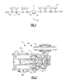
- FIG. 1 a schematic representative of an aircraft's actuation system is shown.
- Multiple actuators 11 may be arranged about a centerline 10 of the aircraft.
- Each of the actuators 11 are driven by an input (shown generically as actuator input 20 in Figure 2 ) from the drive line torque shaft 12, and may be coupled to a load 17 by way of a linkage mechanism 15.
- the drive line torque shaft 12 is driven by a PDU, or power drive unit, 14.
- the load 17 may be a movable aircraft surface, such as a flap, leading edge, or trailing edge of a wing.
- the load 17 generally imparts a torque, or load, on respective actuators 11. This load imparted onto the actuators 11 generally opposes the torque generated by the input from the drive line torque shaft 12.
- each of the actuators 11 include no-backs 16 to prevent back-drive of the actuators 11 and to prevent unwanted displacement of the load 17.
- the no-backs 16 help maintain overall aircraft control.
- the system may further include position sensors 18 at either end of the drive line torque shaft 12 to monitor system position.
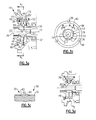
- an actuator 11 including a no-back 16 is shown.
- the no-back 16 may be driven by an actuator input 20, which may be the drive line torque shaft 12.
- the drive line torque shaft 12 may rotate in forward and reverse directions.
- the drive line torque shaft 12 drives the no-back input shaft 30 which, in turn, drives the no-back output shaft 36.
- the no-back output shaft 36 is operatively coupled to the actuator output 22.
- the actuator output 22 may include input and output planetary gears 26 and 28, respectively, in communication with the no-back output shaft 36.
- the actuator output 22 is coupled to the load 17 by way of a linkage mechanism 15 (represented in Figure 1 ).
- the elements included within the no-back 16 are generally within area A. Area A is shown in detail in Figure 3a .
- Figure 3a is representative of the arrangement of the no-back 16 in a no-load condition, and in an opposing-load condition (schematically represented in Figures 4 and 5 , respectively).
- the no-back 16 In the opposing load condition, for example, the no-back 16 is positioned such that it allows the no-back input shaft 30 to transfer rotation to the no-back output shaft 36.
- the no-back input shaft 30, which may be supported by bearing 52, is coupled to the no-back output shaft 36 by way of input and output discs 32, 38 arranged about the outer periphery of input and output shafts 30, 36.
- the input and output discs 32, 38 may be made of a hardened steel or bronze and may be coated with Teflon®, for example.
- the no-back output shaft 36 is only coupled to the output disc 38, whereas the no-back input shaft 30 is operatively coupled to both of the input and output discs 32, 38.
- the input and output discs 32, 38 are rotatably coupled to the no-back input shaft 30 by way of pins 42 arranged about the outer diameter of the no-back input shaft 30, for example.
- the no-back input shaft 30 may include recesses 51 about its outer diameter, each of which may receive a portion of a pin 42.
- the input and output discs 32, 38 may also include recesses 41 and 39, respectively. Each of the recesses 39, 41 are aligned with the recesses 51 to receive a portion of the pins 42.
- the output disc 38 may be coupled to the no-back output shaft 36 by way of a geared, or splined, connection 33.
- Cone brakes 34, 40 are arranged about the outer periphery of (or, radially outward of) the input and output discs 32, 38, respectively.
- the cone brakes 34, 40 may be made of a known steel, for example.
- the cone brakes 34, 40 are coupled to a housing 50 by way of pins 48.
- the cone brakes 34, 40 may be coupled to the housing 50 such that they are rotatably fixed with respect to the input and output discs 32, 38, but can axially slide in the direction of the pins 48.
- the pins 48 may extend generally parallel to the axis 31, and thus the cone brakes 34, 40 may axially slide in the direction of the axis 31.
- a spring 46 may be disposed on one axial side of the cone brake 40 (in Figure 3a , the spring 46 is disposed to the left of the cone brake 40) and may bias (or preload, or urge) the cone brake 40 to the other axial side (in Figure 3a , the spring 46 biases the cone brake 40 to the right).
- the spring 46 may be disposed on the right side of the input disc 32 and may bias the cone brake 34 to the left (again, with reference to Figure 3a ).
- the spring 46 may be a single compression spring, or a set of compression springs, and may be selected of an appropriate material, which may be a hardened steel, for example.
- the spring 46 may contact the disc 40, which in turn contacts output disc 38, but it does not do so with sufficient force to prevent the input and output discs 32, 38 from rotating relative to respective cone brakes 34, 40.
- the spring 46 is utilized to urge (or, preload) the cone brake 40 and the output disc 38 into alignment with input disc 32 and cone brake 34, such that the balls 44 are positioned in the deep center portions 62 of the ballramps 35 and 37 (explained in detail below).
- the inner periphery of the cone brakes 34, 40 may include sloped, or angled, surfaces (generally represented at 70, 72).
- the outer periphery of the input and output discs 32, 38 also include sloped, or angled, surfaces (generally represented at 70, 72) such that the sloped surfaces of the cone brakes 34, 40 correspond with the sloped surfaces of a respective input disc 32, 38.
- Respective sloped surfaces of output disc 38 and cone brake 40 are generally represented by reference numeral 70.
- the sloped surfaces of input disc 32 and cone brake 34 are generally represented by reference numeral 72.
- respective sloped surfaces 70, 72 of the input and output discs 32, 38 and the cone brakes 34, 40 are sloped such that they extend generally parallel to one another.
- the sloped surfaces 70, 72 are sloped, or angled, relative to the axis 31.
- the input and output discs 32, 38 are spaced apart by a distance X1 when in the no-load, or opposing load, condition shown in Figure 3a .
- the spacing of the input and output discs 32, 38 with respect to one another is regulated, in part, by the position of the balls 44 between the input and output discs 32, 38.
- Each of the input and output discs 32, 38 includes a ballramp 37, 35, respectively.
- the ballramps 35, 37 may extend into the input and output discs 32, 38 at a varying depth. The relationship of the position of the balls 44 within the ballramps 35, 37 to the spacing of the input and output discs 32, 38 is explained in detail below.
- the recesses 39 formed in the output disc 38 may be arranged to correspond with the recesses 51 formed in the no-back input shaft 30. As shown, each of the recesses 39 and 51 receives a portion of a pin 42.
- the no-back input shaft 30 is rotatably (or, operatively) coupled to the output disc 38 such that rotation of the no-back input shaft 30 is transferred to the output disc 38.
- Pins 48 may be arranged about the outer periphery of the cone brake 40. The pins 48 may be grounded to the housing 50, thereby preventing the cone brake 40 from rotating, but allowing it to slide axially.
- Kidney-shaped ballramps 35 are formed within the output disc 38, and are sized to receive at least a portion of a ball 44 therein. The ballramps 35 are explained in detail below.
- Figure 3c is a view taken along line B-B, from Figure 3b , and is representative of the varying depth of the ballramps 35, 37 as they extend into the input and output discs 32, 38.
- the ballramp 35 may include a deep center portion 62, which is the deepest portion of the ballramp 35.
- Shallow ends 60, 64 of the ballramp 35 may be sloped, or may taper, downwardly from an outer surface 61 of the output disc 38 toward the deep center portion 62.
- the balls 44 may generally be positioned in the deep center portion 62 of respective ballramps 35, 37.
- This position may be referred to as a neutral position, shown in Figure 3e .
- the balls 44 are positioned such that they extend into the input and output discs 32, 38 relatively deeply, and thus the distance X1 between the input and output discs 32, 38 is relatively small. That is, the input and output discs 32, 38 may be positioned such that the deep center portions 62 of the ballramps 35, 37 are in alignment, and such that the balls 44 are positioned between respective deep center portions 62 of the ballramps 35, 37.
- the spring 46 generally urges the brake 40 such that the input and output discs 32, 38 are aligned, thus causing the balls 44 to settle in the deep center portions 62.
- the no-back 16 is shown in a no-back (or, holding-load) condition (schematically represented in Figure 6 ).
- a no-back condition may be created when the actuator input 20 is insufficient to oppose the load 17, or when the actuator input 20 fails (due to a failure of the PDU 14 or the drive line torque shaft 12, for example).
- the load 17 may cause reverse rotation of the no-back output shaft 36, which in turn may cause output disc 38 to rotate relative to input disc 32 (because the no-back output shaft 36 is only coupled to the output disc 38, and not both of the input and output discs 32, 38).
- the deep center portions 62 of the ballramps 35, 37 will also rotate out of alignment, and the balls 44 will be moved toward the shallow ends 60, 64 of the ballramps 35, 37, as shown in Figure 3f .
- the positioning of the balls 44 causes the output disc 38 to become axially spaced from input disc 32 by a distance X2 (this position may be referred to as an extended position, shown in Figure 3f ), which is greater than the distance X1.
- This positioning of the balls 44 generates an axial load on the input and output discs 32, 38 greater than the preload (or biasing force) generated by the spring 46.
- the output disc 38 engages the cone brake 40 (by way of their respective sloped surfaces 70) and causes the cone brake 40 to axially slide with the output disc 38 (to the left in Figure 3d ).
- an axial load is generated by the balls 44 that is transferred to both discs 32 and 38.
- This axial load generated by the balls 44 passes from the input and output discs 32, 38 to the cone brakes 34, 40, thus displacing output disc 38 and cone brake 40 (to the left in Figure 3d ) relative to their position in the no-load and opposing-load conditions shown in Figure 3a .
- the cone brake 40 thus compresses the spring 46 against the spacer 80 and retaining ring 81, both of which are fixed to the housing 50.
- the cone brake 40 is urged toward the output disc 38 against the axial load generated by the positioning of the balls 44.
- the cone brake 40 is wedged into the output disc 38 by way of the respective sloped surfaces 70.
- This wedging action thus creates a frictional force between the cone brake 40 and the output disc 38 and between cone brake 34 and the input disc 32, respectively, creating a combined resistance torque (Tr) sufficient to overcome the torque created by load 17 on the no-back output shaft 36 (Tload).
- Tr combined resistance torque
- G T r T load
- gain (G) including: the materials chosen for the input and output discs 32, 38 and the cone brakes 34, 40; the slope of the sloped surfaces 70, 72; the dimensions of the ballramps 35, 37, etc.
- the gain (G) In order for the no-back 16 to work properly, the gain (G) must be greater than 1 when in the no-back condition. That is, the above-mentioned factors must be set such that Tr > Tload when in the no-back condition.
- Figure 3e is a view taken along line A2-A2 from Figure 3a and shows the balls 44 arranged between the ballramps 35, 37 of the input and output discs 32, 38 such that the discs are spaced apart by a distance X1.
- Figure 3e is representative of a neutral position.
- the neutral position may be present during a no-load condition (schematically represented in Figure 4 ) and an opposing load condition (schematically represented in Figure 5 ).
- the neutral position exists when the deep center portions 62 of the respective input and output discs 32, 38 are in alignment, and the balls 44 are positioned between respective deep center portions 62.
- Figure 3f is a view taken along line C-C from Figure 3d and shows the balls 44 arranged between the ballramps 35, 37 of the input and output discs 32, 38 such that input and output discs 32, 38 are spaced apart by a distance X2.
- Figure 3f is representative of an extended position.
- the extended position may be present during the no-back condition or during an aiding-load condition (schematically represented in Figures 6 and 7 , respectively).
- the extended position exists when the deep center portions 62 of the respective input and output discs 32, 38 are out of alignment, and the balls 44 are positioned between respective shallow ends 60, 64 of the ballramps 35, 37. This positioning of the balls 44 creates an axial load on the input and output discs 32, 38 sufficient to overcome the preload (or biasing force) of the spring 46.
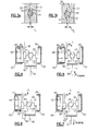
- the no-back 16 is schematically represented in a no-load condition.
- the no-load condition is also represented in Figure 3a .
- the load 17 may be present, but may be positioned in a rest position so as to not impart a torque, or load (such as Tload), on the no-back output shaft 36.
- there may be no input e.g., from actuator input 20
- the ball 44 is positioned in the center (shown as the deep center portion 62 in Figure 3c ) of respective ballramps 35, 37.
- Cone brakes 34, 40 are positioned outside of, or about the outer periphery of, the input and output discs 32, 38.
- spring 46 is positioned between the cone brake 40 and the housing 50 (the spring 46 may actually be in operative connection with the housing 50 by way of the spacer 80 and retaining ring 81, as shown in Figure 3a , for example).
- the no-back 16 is schematically represented in an opposing-load condition (which is also represented in Figure 3a ).
- a forward input, Iforward is sufficient to oppose, or overcome a load, L. That is, the forward input, Iforward, drives the no-back output shaft 36 in a forward rotational direction, such that the load L, which generally urges the no-back output shaft 36 in a reverse rotational direction, is opposed.
- the load 17 is generally maintained in a desired position by virtue of the forward input, Iforward.
- the forward input, Iforward is shown as engaging the input and output discs 32, 38 by way of a pin 42 (as described above).
- the no-back 16 is shown in a no-back condition (also depicted in Figure 3d ).
- the no-back condition which is generally described above, may be caused by the failure of the drive line torque shaft 12 or the PDU 14, for example. In either case, the no-back input shaft 30 would not impart a forward input Iforward sufficient to oppose the load L. In fact, when in the no-back condition there may be no input present at all (as the drive line torque shaft may have completely failed, for example). Regardless, when the forward input Iforward is insufficient to oppose the load L, the no-back output shaft 36 is urged in a reverse rotational direction.
- the input and output discs 32, 38 are brought out of alignment. That is, the ballramps 35, 37 of the input and output discs 32, 38 are brought out of alignment with one another. As explained above, this misalignment causes the balls 44 to be positioned away from the center of the ballramps 35, 37 and toward the shallow end portions 60, 64, for example (see Figure 3c ). Because of this positioning of the balls 44 within the ballramps 35, 37, the input and output discs 32, 38 are spaced relative to one another (generally indicated as the distance X2 in Figures 3d and 3f ).
- this relative movement of the input and output discs 32, 38 is represented by downward movement of the output disc 38. Movement of the output disc 38 also causes the cone brake 40 to move toward the spring 46 and the housing 50 (the spring 46 may contact the housing 50 by way of the spacer 80 and retaining ring 81).
- the axial load that is generated by the positioning of the balls 44 within the ballramps 35 and 37 is sufficient to generate friction between the cone brake 40 and the output disc 38 and between the cone brake 34 and the input disc 32.
- This friction between the input and output discs 32, 38 and the cone brakes 34, 40 generates a combined resistance torque (Tr) sufficient to overcome the torque imparted onto the no-back output shaft 36 by the load L, defined above as Tload.
- Tload combined resistance torque
- the no-back 16 is shown in an aiding-load condition, wherein the no-back 16 may be released from the no-back condition.
- the no-back 16 can be released by adjusting the resistance torque (Tr). This may be accomplished by applying, a reverse input, Ireverse, to the no-back input shaft 30 of a sufficient magnitude to reduce the gain (G) to less than 1. In this way, the resistance torque (Tr) is reduced and rotation of the input and output discs 32, 38 and input and output shafts 30, 36 is again possible.
- no-back 16 has been described with reference to cone brakes 34, 40, alternate brake designs are contemplated within the scope of this disclosure. That is, the cone brakes 34, 40 may be representative of any brake arranged radially outward of the input and output discs 32, 38. Further, while the no-back 16 has been described with reference to use in aircrafts, one of ordinary skill would recognize that the no-back 16 need not be limited to use in aircrafts, and indeed may be applicable for use in other settings. Accordingly, the following claims should be studied to determine their true scope and content.
Landscapes
- Engineering & Computer Science (AREA)
- General Engineering & Computer Science (AREA)
- Mechanical Engineering (AREA)
- Automation & Control Theory (AREA)
- Aviation & Aerospace Engineering (AREA)
- Braking Arrangements (AREA)
Abstract
Disclosed is a cone brake no-back (16) for use with an actuation system. The actuation system may be an aircraft actuation system, for example. The no-back may include cone brakes (40,34) capable of preventing undesired displacement of an aircraft surface (such as a flap, a leading edge, or a trailing edge of a wing) in the event that an actuator input becomes disconnected or is otherwise insufficient to oppose the load created by the aircraft surface.
Description
- This disclosure relates to a no-back for use with an actuation system.
- No-backs are typically used with aircraft actuators, which may be used to displace an aircraft surface, such as a flap, a leading edge, or a trailing edge of a wing. Multiple actuators may be positioned on opposing sides of an aircraft, and are typically driven by an input, which may be a drive line torque shaft. In the event of failure or disconnect of the drive line torque shaft, for example, a no-back will prevent an associated aircraft surface from being displaced from a desired position.
- Disclosed is a no-back assembly comprising a first disc coupled to a first shaft and arranged radially outward of the first shaft and a first brake arranged radially outward of the first disc, the first brake being configured to prevent the first disc from rotating when in a no-back condition. In an embodiment, the no-back assembly includes first and second discs coupled to respective first and second shafts. The first and second discs are arranged radially outward of respective first and second shafts. The no-back assembly also includes first and second brakes arranged radially outward of respective first and second discs. The first and second brakes are configured to prevent the first and second discs from rotating when in a no-back condition.
- Also disclosed is a system including an actuator with a shaft receiving an input and being coupled to a load. The system further includes a disc in communication with the shaft. When in a no-back condition, the disc is brought into contact with a brake disposed about the outer periphery of the disc such that the shaft is substantially prevented from rotating.
- Further disclosed is a method wherein a disc is rotated in a first rotational direction when in a first operational state. The disc is then moved in a first axial direction when in a second operational state. A brake is urged in a second axial direction, opposite the first axial direction, in the second operational state such that the brake is wedged into the disc and thus prevents the disc from rotating.
- These and other features can be best understood from the following specification and drawings, the following of which is a brief description.
-
-
Figure 1 is a schematic representative of an aircraft's actuation system; -
Figure 2 is a typical rotary actuator including a cone brake no-back; -
Figure 3a is a view of area A fromFigure 2 depicting the cone brake no-back in a no-load, or opposing load, condition; -
Figure 3b is a section taken along line A1-A1 fromFigure 3a ; -
Figure 3c is a section taken along line B-B fromFigure 3b ; -
Figure 3d is a view of area A fromFigure 2 depicting the cone brake no-back in a no-back condition; -
Figure 3e is a section taken along line A2-A2 fromFigure 3a ; -
Figure 3f is a section taken along line C-C fromFigure 3d ; -
Figure 4 is a schematic representative of the no-back in a no-load condition; -
Figure 5 is a schematic representative of the no-back in an opposing load condition; -
Figure 6 is a schematic representative of the no-back in a no-back condition;
and -
Figure 7 is a schematic representative of the no-back in an aiding load condition. - Referring to
Figure 1 , a schematic representative of an aircraft's actuation system is shown.Multiple actuators 11 may be arranged about a centerline 10 of the aircraft. Each of theactuators 11 are driven by an input (shown generically asactuator input 20 inFigure 2 ) from the driveline torque shaft 12, and may be coupled to aload 17 by way of alinkage mechanism 15. The driveline torque shaft 12 is driven by a PDU, or power drive unit, 14. Theload 17 may be a movable aircraft surface, such as a flap, leading edge, or trailing edge of a wing. Theload 17 generally imparts a torque, or load, onrespective actuators 11. This load imparted onto theactuators 11 generally opposes the torque generated by the input from the driveline torque shaft 12. In a system without no-backs 16, an input insufficient to oppose the load 17 (e.g., if the drive line torque shaft or the PDU were to fail) may cause theactuator 11 to back-drive, thus causing theload 17 to displace from a desired position. Thus, each of theactuators 11 include no-backs 16 to prevent back-drive of theactuators 11 and to prevent unwanted displacement of theload 17. In this regard, the no-backs 16 help maintain overall aircraft control. The system may further include position sensors 18 at either end of the driveline torque shaft 12 to monitor system position. - Referring to
Figure 2 , anactuator 11 including a no-back 16 is shown. As explained, the no-back 16 may be driven by anactuator input 20, which may be the driveline torque shaft 12. The driveline torque shaft 12 may rotate in forward and reverse directions. The driveline torque shaft 12 drives the no-back input shaft 30 which, in turn, drives the no-back output shaft 36. The no-back output shaft 36 is operatively coupled to theactuator output 22. Theactuator output 22 may include input and outputplanetary gears 26 and 28, respectively, in communication with the no-back output shaft 36. Theactuator output 22 is coupled to theload 17 by way of a linkage mechanism 15 (represented inFigure 1 ). The elements included within the no-back 16 are generally within area A. Area A is shown in detail inFigure 3a . -
Figure 3a , is representative of the arrangement of the no-back 16 in a no-load condition, and in an opposing-load condition (schematically represented inFigures 4 and 5 , respectively). In the opposing load condition, for example, the no-back 16 is positioned such that it allows the no-back input shaft 30 to transfer rotation to the no-back output shaft 36. The no-back input shaft 30, which may be supported by bearing 52, is coupled to the no-back output shaft 36 by way of input andoutput discs output shafts output discs back output shaft 36 is only coupled to theoutput disc 38, whereas the no-back input shaft 30 is operatively coupled to both of the input andoutput discs - The input and
output discs back input shaft 30 by way ofpins 42 arranged about the outer diameter of the no-back input shaft 30, for example. The no-back input shaft 30 may includerecesses 51 about its outer diameter, each of which may receive a portion of apin 42. The input andoutput discs recesses 41 and 39, respectively. Each of therecesses 39, 41 are aligned with therecesses 51 to receive a portion of thepins 42. Further, theoutput disc 38 may be coupled to the no-back output shaft 36 by way of a geared, or splined,connection 33. -
Cone brakes output discs cone brakes cone brakes housing 50 by way ofpins 48. Thecone brakes housing 50 such that they are rotatably fixed with respect to the input andoutput discs pins 48. Thepins 48 may extend generally parallel to theaxis 31, and thus thecone brakes axis 31. Aspring 46 may be disposed on one axial side of the cone brake 40 (inFigure 3a , thespring 46 is disposed to the left of the cone brake 40) and may bias (or preload, or urge) thecone brake 40 to the other axial side (inFigure 3a , thespring 46 biases thecone brake 40 to the right). Alternatively, thespring 46 may be disposed on the right side of theinput disc 32 and may bias thecone brake 34 to the left (again, with reference toFigure 3a ). Thespring 46 may be a single compression spring, or a set of compression springs, and may be selected of an appropriate material, which may be a hardened steel, for example. - In the no-load and opposing load conditions, the
spring 46 may contact thedisc 40, which in turncontacts output disc 38, but it does not do so with sufficient force to prevent the input andoutput discs respective cone brakes spring 46 is utilized to urge (or, preload) thecone brake 40 and theoutput disc 38 into alignment withinput disc 32 andcone brake 34, such that theballs 44 are positioned in thedeep center portions 62 of theballramps 35 and 37 (explained in detail below). The inner periphery of thecone brakes output discs cone brakes respective input disc output disc 38 andcone brake 40 are generally represented by reference numeral 70. The sloped surfaces ofinput disc 32 andcone brake 34 are generally represented byreference numeral 72. As seen inFigure 3a , respectivesloped surfaces 70, 72 of the input andoutput discs cone brakes axis 31. - The input and
output discs Figure 3a . The spacing of the input andoutput discs balls 44 between the input andoutput discs output discs ballramp ballramps output discs balls 44 within theballramps output discs - Referring to
Figure 3b , a view taken along line A1-A1, fromFigure 3a , is shown. As explained, therecesses 39 formed in theoutput disc 38 may be arranged to correspond with therecesses 51 formed in the no-back input shaft 30. As shown, each of therecesses pin 42. In this manner, the no-back input shaft 30 is rotatably (or, operatively) coupled to theoutput disc 38 such that rotation of the no-back input shaft 30 is transferred to theoutput disc 38.Pins 48 may be arranged about the outer periphery of thecone brake 40. Thepins 48 may be grounded to thehousing 50, thereby preventing thecone brake 40 from rotating, but allowing it to slide axially. Kidney-shapedballramps 35 are formed within theoutput disc 38, and are sized to receive at least a portion of aball 44 therein. Theballramps 35 are explained in detail below. -
Figure 3c is a view taken along line B-B, fromFigure 3b , and is representative of the varying depth of theballramps output discs ballramp 35 may include adeep center portion 62, which is the deepest portion of theballramp 35. Shallow ends 60, 64 of theballramp 35 may be sloped, or may taper, downwardly from anouter surface 61 of theoutput disc 38 toward thedeep center portion 62. When the no-back 16 is in the no-load and opposing-load conditions (as shown inFigure 3a and as schematically represented inFigures 4 and 5 ), theballs 44 may generally be positioned in thedeep center portion 62 ofrespective ballramps Figure 3e . In this way, theballs 44 are positioned such that they extend into the input andoutput discs output discs output discs deep center portions 62 of theballramps balls 44 are positioned between respectivedeep center portions 62 of theballramps spring 46 generally urges thebrake 40 such that the input andoutput discs balls 44 to settle in thedeep center portions 62. - Referring to
Figure 3d , the no-back 16 is shown in a no-back (or, holding-load) condition (schematically represented inFigure 6 ). Such a no-back condition may be created when theactuator input 20 is insufficient to oppose theload 17, or when theactuator input 20 fails (due to a failure of thePDU 14 or the driveline torque shaft 12, for example). In absence ofactuator input 20, or when theactuator input 20 is insufficient to oppose theload 17, theload 17 may cause reverse rotation of the no-back output shaft 36, which in turn may causeoutput disc 38 to rotate relative to input disc 32 (because the no-back output shaft 36 is only coupled to theoutput disc 38, and not both of the input andoutput discs 32, 38). In this regard, thedeep center portions 62 of theballramps balls 44 will be moved toward the shallow ends 60, 64 of theballramps Figure 3f . Because the shallow ends 60, 64 do not extend as deeply into the respective input andoutput discs deep center portion 62, the positioning of theballs 44 causes theoutput disc 38 to become axially spaced frominput disc 32 by a distance X2 (this position may be referred to as an extended position, shown inFigure 3f ), which is greater than the distance X1. This positioning of theballs 44 generates an axial load on the input andoutput discs spring 46. - As the
balls 44 are positioned toward the shallow ends 60, 64 of theballramps output disc 38 engages the cone brake 40 (by way of their respective sloped surfaces 70) and causes thecone brake 40 to axially slide with the output disc 38 (to the left inFigure 3d ). Again, as theload 17 is applied to the no-back output shaft 36, and then to theoutput disc 38, an axial load is generated by theballs 44 that is transferred to bothdiscs balls 44 passes from the input andoutput discs cone brakes output disc 38 and cone brake 40 (to the left inFigure 3d ) relative to their position in the no-load and opposing-load conditions shown inFigure 3a . Thecone brake 40 thus compresses thespring 46 against thespacer 80 and retainingring 81, both of which are fixed to thehousing 50. By way of the compression of thespring 46, thecone brake 40 is urged toward theoutput disc 38 against the axial load generated by the positioning of theballs 44. In this manner, thecone brake 40 is wedged into theoutput disc 38 by way of the respective sloped surfaces 70. This wedging action thus creates a frictional force between thecone brake 40 and theoutput disc 38 and betweencone brake 34 and theinput disc 32, respectively, creating a combined resistance torque (Tr) sufficient to overcome the torque created byload 17 on the no-back output shaft 36 (Tload). In this manner, the no-back input andoutput shafts output discs load 17 is prevented from being displaced, and the no-back condition is effectively provided. - The following relationship may be referred to as gain (G).

- One of ordinary skill will appreciate that several factors may affect gain (G) including: the materials chosen for the input and
output discs cone brakes ballramps -
Figure 3e is a view taken along line A2-A2 fromFigure 3a and shows theballs 44 arranged between theballramps output discs Figure 3e is representative of a neutral position. The neutral position may be present during a no-load condition (schematically represented inFigure 4 ) and an opposing load condition (schematically represented inFigure 5 ). The neutral position exists when thedeep center portions 62 of the respective input andoutput discs balls 44 are positioned between respectivedeep center portions 62. -
Figure 3f is a view taken along line C-C fromFigure 3d and shows theballs 44 arranged between theballramps output discs output discs Figure 3f is representative of an extended position. The extended position may be present during the no-back condition or during an aiding-load condition (schematically represented inFigures 6 and 7 , respectively). The extended position exists when thedeep center portions 62 of the respective input andoutput discs balls 44 are positioned between respective shallow ends 60, 64 of theballramps balls 44 creates an axial load on the input andoutput discs spring 46. - Referring to
Figure 4 , the no-back 16 is schematically represented in a no-load condition. The no-load condition is also represented inFigure 3a . Notably, in the no-load condition, theload 17 may be present, but may be positioned in a rest position so as to not impart a torque, or load (such as Tload), on the no-back output shaft 36. Thus, there may be no input (e.g., from actuator input 20), as there is no load for the input to oppose. As can be seen inFigure 4 , theball 44 is positioned in the center (shown as thedeep center portion 62 inFigure 3c ) ofrespective ballramps output discs ballramp Cone brakes output discs spring 46 is positioned between thecone brake 40 and the housing 50 (thespring 46 may actually be in operative connection with thehousing 50 by way of thespacer 80 and retainingring 81, as shown inFigure 3a , for example). - Referring to
Figure 5 , the no-back 16 is schematically represented in an opposing-load condition (which is also represented inFigure 3a ). In this condition, a forward input, Iforward, is sufficient to oppose, or overcome a load, L. That is, the forward input, Iforward, drives the no-back output shaft 36 in a forward rotational direction, such that the load L, which generally urges the no-back output shaft 36 in a reverse rotational direction, is opposed. In this manner, theload 17 is generally maintained in a desired position by virtue of the forward input, Iforward. Note that the forward input, Iforward, is shown as engaging the input andoutput discs - Referring to
Figure 6 , the no-back 16 is shown in a no-back condition (also depicted inFigure 3d ). The no-back condition, which is generally described above, may be caused by the failure of the driveline torque shaft 12 or thePDU 14, for example. In either case, the no-back input shaft 30 would not impart a forward input Iforward sufficient to oppose the load L. In fact, when in the no-back condition there may be no input present at all (as the drive line torque shaft may have completely failed, for example). Regardless, when the forward input Iforward is insufficient to oppose the load L, the no-back output shaft 36 is urged in a reverse rotational direction. Since the no-back output shaft 36 is only coupled to theoutput disc 38, rather than both of the input andoutput discs output discs ballramps output discs balls 44 to be positioned away from the center of theballramps shallow end portions Figure 3c ). Because of this positioning of theballs 44 within theballramps output discs Figures 3d and3f ). InFigure 6 , this relative movement of the input andoutput discs output disc 38. Movement of theoutput disc 38 also causes thecone brake 40 to move toward thespring 46 and the housing 50 (thespring 46 may contact thehousing 50 by way of thespacer 80 and retaining ring 81). The axial load that is generated by the positioning of theballs 44 within theballramps cone brake 40 and theoutput disc 38 and between thecone brake 34 and theinput disc 32. This friction between the input andoutput discs cone brakes back output shaft 36 by the load L, defined above as Tload. Thereby, no-back 16 prevents theload 17 from being displaced, and the no-back condition is effectively provided. - Referring to
Figure 7 , the no-back 16 is shown in an aiding-load condition, wherein the no-back 16 may be released from the no-back condition. Essentially, the no-back 16 can be released by adjusting the resistance torque (Tr). This may be accomplished by applying, a reverse input, Ireverse, to the no-back input shaft 30 of a sufficient magnitude to reduce the gain (G) to less than 1. In this way, the resistance torque (Tr) is reduced and rotation of the input andoutput discs output shafts - A worker of ordinary skill in this art would recognize that certain modifications of the instant disclosure would come within the scope of the claims. For example, although the no-
back 16 has been described with reference tocone brakes cone brakes output discs back 16 has been described with reference to use in aircrafts, one of ordinary skill would recognize that the no-back 16 need not be limited to use in aircrafts, and indeed may be applicable for use in other settings. Accordingly, the following claims should be studied to determine their true scope and content.
Claims (15)
- A no-back assembly (16) comprising:a first disc (38) coupled to a first shaft (36) and arranged radially outward of the first shaft (36); anda first brake (40) arranged radially outward of the first disc (38), the first brake being configured to prevent the first disc (38) from rotating when in a no-back condition.
- The no-back assembly (16) of claim 1 further including:a second disc (32) coupled to a second shaft (30) and arranged radially outward of the second shaft (30); anda second brake (34) arranged radially outward of the second disc (32), the second brake (34) being configured to prevent the second disc (32) from rotating when in the no-back condition.
- The no-back assembly of claim 2 further including that the first disc (38) is an output disc, the first shaft (36) is an output shaft, the second disc (32) is an input disc, and the second shaft (30) is an input shaft; and
wherein the first disc (38) is arranged radially outward of the first and second shafts (36,30). - The no-back assembly (16) of claims 2 or 3 wherein, when in the no-back condition, the first and second brakes (40,34) are brought into contact with respective first and second discs (38,32), and thereby the first and second shafts (36,30) are substantially prevented from rotating.
- The no-back assembly (16) of claim 4 wherein the first shaft (36) is urged in forward rotational direction by a forward input and is urged in a reverse rotational direction by a load, the reverse rotational direction opposite the forward rotational direction, the first shaft (36) being operatively coupled to the second shaft (30).
- The no-back assembly (16) of claim 5 wherein, when in the no-back condition, there is no input.
- The no-back assembly (16) of any of claims 2 to 6 wherein each of the first and second brakes (40,34) are rotatably fixed relative to the first and second discs (38,32) and include a sloped surface (70,72) on an inner periphery thereof, the sloped surfaces (70,72) of the first and second brakes (40,34) being inclined relative to an axis (31) of the first and second shafts (36,30), each of the first and second discs (38,32) including a sloped surface (70,72) about the outer periphery thereof, the sloped surfaces (70,72) of the first and second discs (38,32) inclined to be substantially parallel to the sloped surfaces (70,72) of respective first and second brakes (40,34).
- The no-back assembly (16) of claim 7 wherein, when in the no-back condition, the sloped surfaces (70,72) of the first and second brakes (30,36) are brought into contact with respective sloped surfaces (70,72) of the first and second discs (38,32) such that a resistance torque is generated that is larger than a torque created by the load urging the first shaft (36) in the reverse rotational direction.
- The no-back assembly (16) of any of claims 2 to 8 further including that each of the first and second discs (38,32) include a ballramp (35,37) formed therein, respective ballramps (35,37) of the first and second discs (38,32) being generally aligned with and facing one another.
- The no-back assembly (16) of claim 9 further including that a ball (44) is positioned between the first and second discs (38,32) such that the ball (44) is supported partially by the ballramp (35,37) of the first disc (38) and partially by the ballramp (35,37) of the second disc (32).
- The no-back assembly (16) of claim 9 or 10 wherein each of the ballramps (35,37) are formed with a varying depth, the ballramps (35,37) being deepest at a center portion, ends of the ballramps (35,37) including sloped portions such that the ballramps (35,37) taper downwardly from the ends to the center portion.
- The no-back assembly (16) of any preceding claim wherein the first brake (40) is axially slidable and rotatably fixed relative to a housing (50), the first brake (40) is in contact with a spring (46) on a first side of the first brake (40) and is in contact with the first disc (38) on a second side of the first brake (40), the second side of the first brake (40) being generally opposite the first side of the first brake (40).
- The no-back assembly (16) of claim 12 wherein, when in the no-back condition, the ball (44) is positioned such that it contacts the sloped portion of the ballramps (35,37) of the first disc (38) and the sloped portion of the ballramp (35,37) of the second disc (32), and thereby the first disc (38) is displaced in a first axial direction and causes the first brake (40) to slide axially in the first axial direction toward the spring (46), the spring (46) urges the first brake (40) in a second axial direction opposite the first axial direction such that the sloped surfaces of the first and second brakes (40,34) are brought into contact with the sloped surfaces of respective first and second discs (38,32), thereby substantially preventing the first and second discs (38,32) and the first and second shafts (36,30) from rotating.
- A system comprising:an actuator (11) including a shaft (12) receiving an input and coupled to a load (17);a disc (38,32) in communication with the shaft (12); andwhen in a no-back condition, the disc (38,32) is brought into contact with a brake (40,34) disposed about the outer periphery of the disc (38,32) such that the disc (38,32) and the shaft (12) are substantially prevented from rotating.
- A method comprising the steps of:a) rotating a disc (38,32) in a first rotational direction when in a first operational state;b) moving the disc (38,32) in a first axial direction when in a second operational state; andc) when in the second operational state, urging a brake (40,34) in a second axial direction opposite the first axial direction such that the brake (40,34) is wedged into the disc (38,32) and thus prevents the disc (38,32) from rotating.
Applications Claiming Priority (1)
| Application Number | Priority Date | Filing Date | Title |
|---|---|---|---|
| US12/752,417 US8511441B2 (en) | 2010-04-01 | 2010-04-01 | Cone brake no-back |
Publications (1)
| Publication Number | Publication Date |
|---|---|
| EP2371709A2 true EP2371709A2 (en) | 2011-10-05 |
Family
ID=44278863
Family Applications (1)
| Application Number | Title | Priority Date | Filing Date |
|---|---|---|---|
| EP11160752A Withdrawn EP2371709A2 (en) | 2010-04-01 | 2011-03-31 | Cone brake no-back |
Country Status (6)
| Country | Link |
|---|---|
| US (1) | US8511441B2 (en) |
| EP (1) | EP2371709A2 (en) |
| KR (1) | KR101356307B1 (en) |
| CN (1) | CN102213282A (en) |
| BR (1) | BRPI1101641B1 (en) |
| CA (1) | CA2734341C (en) |
Cited By (3)
| Publication number | Priority date | Publication date | Assignee | Title |
|---|---|---|---|---|
| WO2017067659A1 (en) * | 2015-10-21 | 2017-04-27 | Liebherr-Aerospace Lindenberg Gmbh | Actuating drive for a high-lift system of an aircraft |
| EP3140568A4 (en) * | 2014-05-08 | 2018-01-10 | Dura Operating, LLC | Anti-backdrive actuator assembly |
| FR3058983A1 (en) * | 2016-11-22 | 2018-05-25 | Safran Electronics & Defense | EASILY MOUNTED ACTUATOR |
Families Citing this family (12)
| Publication number | Priority date | Publication date | Assignee | Title |
|---|---|---|---|---|
| US9651126B2 (en) | 2010-09-30 | 2017-05-16 | Hamilton Sundstrand Corporation | Cone brake load limiter method and apparatus |
| LV14610B (en) * | 2011-05-02 | 2013-01-20 | Baltrotors, Sia | Vibration damper with disc brakes and their adjustment mechanism |
| CN103122958B (en) * | 2011-11-21 | 2016-05-04 | 哈米尔顿森德斯特兰德公司 | Cone brake load limiter method and apparatus |
| US8978840B2 (en) * | 2012-11-19 | 2015-03-17 | Hamilton Sundstrand Corporation | Asymmetry brake with torque limit |
| DE102013000544A1 (en) * | 2013-01-15 | 2014-07-17 | Liebherr-Aerospace Lindenberg Gmbh | Return stopper for use in gear box of geared rotary actuator in high lift system of airplane, has brake element staying in connection with ramp plates in certain position to prevent movement of plates by friction effect with brake element |
| US9863515B2 (en) * | 2014-03-18 | 2018-01-09 | Parker-Hannifin Corporation | Self-locking no-back actuator |
| US9616990B2 (en) | 2014-07-18 | 2017-04-11 | Hamilton Sundstrand Corporation | Aircraft component rotary device |
| US9527580B2 (en) * | 2014-09-24 | 2016-12-27 | Hamilton Sundstrand Corporation | Cone brake no-back assembly with gain reduction spring and method |
| DE102017129222B4 (en) | 2017-12-08 | 2026-02-26 | Liebherr-Aerospace Lindenberg Gmbh | Reverse brake for an aircraft |
| US10935115B2 (en) | 2018-08-20 | 2021-03-02 | Hamilton Sunstrand Corporation | Linear actuator with testable cone no-back and torque limiter |
| US11440640B2 (en) * | 2018-12-18 | 2022-09-13 | The Boeing Company | Bi-directional no-back brake progressive modulation spring systems and methods |
| US11906006B2 (en) | 2021-10-08 | 2024-02-20 | Honeywell International Inc. | Self-activated no-back device |
Family Cites Families (35)
| Publication number | Priority date | Publication date | Assignee | Title |
|---|---|---|---|---|
| US1774144A (en) * | 1928-05-22 | 1930-08-26 | Jones Webster | Shock absorber |
| US2089996A (en) * | 1932-10-08 | 1937-08-17 | Gustave Fast Engineering Corp | Brake construction |
| US2063445A (en) * | 1935-03-28 | 1936-12-08 | Homer T Lambert | Momentum-actuated brake apparatus |
| US2675898A (en) * | 1950-09-12 | 1954-04-20 | Connecticut Variable Gear Corp | Unidirectional drive coupling |
| US3722641A (en) | 1971-09-16 | 1973-03-27 | United Aircraft Corp | No back actuator system |
| US4176733A (en) * | 1978-04-26 | 1979-12-04 | Sundstrand Corporation | Combination no-back brake and torque limiter assembly |
| GB2034834B (en) * | 1978-10-17 | 1982-11-10 | Powell R E | Disc brake assemblies |
| US4582187A (en) * | 1981-12-30 | 1986-04-15 | Facet Enterprises Inc. | Self-adjusting electromagnetic cone brake with overrunning adjustment assembly |
| US4483429A (en) | 1982-01-08 | 1984-11-20 | Curtiss-Wright Flight Systems, Inc. | Dual function torque limiter/no-back device |
| US4697672A (en) | 1985-03-25 | 1987-10-06 | Sundstrand Corporation | Bi-directional force limiting no-back mechanism |
| US4693349A (en) * | 1986-07-25 | 1987-09-15 | Sundstrand Corporation | Torque limiting apparatus |
| US4909363A (en) * | 1987-06-15 | 1990-03-20 | Sundstrand Corporation | Unidirectional no-back device |
| US4850458A (en) * | 1988-11-16 | 1989-07-25 | Boeing Company | Bidirectional rotary brake |
| EP0460003B1 (en) * | 1989-02-23 | 1993-05-12 | ZF FRIEDRICHSHAFEN Aktiengesellschaft | Drive device with variable torque-limiting system |
| US5090529A (en) * | 1990-05-16 | 1992-02-25 | Ivg Australia Pty. Limited | Brake mechanism |
| US5299676A (en) * | 1991-08-15 | 1994-04-05 | Ivg Australia Pty. Limited | Rotation check mechanism |
| US5353901A (en) | 1992-09-24 | 1994-10-11 | Sundstrand Corporation | Pilot operated no-back |
| US5582390A (en) | 1994-11-17 | 1996-12-10 | Sundstrand Corporation | Drive apparatus with primary and secondary no-back features |
| GB9503191D0 (en) * | 1995-02-18 | 1995-04-05 | Lucas Ind Plc | Torque limiter |
| US5655636A (en) | 1995-06-02 | 1997-08-12 | Sundstrand Corporation | Compact actuator including resettable force limiting and anti-backdrive devices |
| US5943911A (en) | 1998-05-11 | 1999-08-31 | Borg-Warner Automotive, Inc. | Electromechanical friction clutch control for a manual transmission |
| US5944148A (en) * | 1998-08-31 | 1999-08-31 | The Boeing Company | No-back brake |
| JP2000097308A (en) | 1998-09-24 | 2000-04-04 | Shimadzu Corp | No back device |
| US6202803B1 (en) | 1998-12-22 | 2001-03-20 | Hamilton Sundstrand Corporation | Output load limiter |
| GB0105270D0 (en) | 2001-03-02 | 2001-04-18 | Lucas Industries Ltd | No-back device |
| GB0122321D0 (en) * | 2001-09-15 | 2001-11-07 | Lucas Industries Ltd | Helicopter rotor blade locking pin braking asembly |
| GB0215727D0 (en) | 2002-07-06 | 2002-08-14 | Lucas Industries Ltd | No-back device |
| US6666307B1 (en) | 2002-08-05 | 2003-12-23 | Honeywell International, Inc. | Thrust reverser system with a pass-through torque activated brake |
| US6814209B1 (en) | 2003-05-29 | 2004-11-09 | Siemens Vdo Automotive Corporation | Inertia clutch mechanism in motors to prevent backdrive |
| US7163097B2 (en) | 2004-02-26 | 2007-01-16 | Siemens Vdo Automotive Corporation | Bi-directional friction clutch assembly for electric motors to prevent backdrive |
| US7143888B2 (en) * | 2005-01-26 | 2006-12-05 | Hamilton Sundstrand Corporation | Combined no-back and torque limiter |
| FR2905997B1 (en) * | 2006-09-14 | 2008-11-28 | Conseil Et Tech Sarl | FRICTION DEVICE FOR EFFORT CONTROL, AND A FRICTION DAMPER COMPRISING SUCH A DEVICE |
| CA2676064A1 (en) * | 2007-02-01 | 2008-08-07 | Edward A. Mayer | Torque brake |
| US8215471B2 (en) * | 2008-04-28 | 2012-07-10 | Auma Riester Gmbh & Co. Kg | Mechanical brake |
| US8960031B2 (en) * | 2009-09-01 | 2015-02-24 | Parker-Hannifin Corporation | Aircraft stabilizer actuator |
-
2010
- 2010-04-01 US US12/752,417 patent/US8511441B2/en active Active
-
2011
- 2011-03-17 CA CA2734341A patent/CA2734341C/en active Active
- 2011-03-18 KR KR1020110024155A patent/KR101356307B1/en active Active
- 2011-03-31 EP EP11160752A patent/EP2371709A2/en not_active Withdrawn
- 2011-04-01 BR BRPI1101641-8A patent/BRPI1101641B1/en active IP Right Grant
- 2011-04-01 CN CN2011100819264A patent/CN102213282A/en active Pending
Non-Patent Citations (1)
| Title |
|---|
| None |
Cited By (5)
| Publication number | Priority date | Publication date | Assignee | Title |
|---|---|---|---|---|
| EP3140568A4 (en) * | 2014-05-08 | 2018-01-10 | Dura Operating, LLC | Anti-backdrive actuator assembly |
| WO2017067659A1 (en) * | 2015-10-21 | 2017-04-27 | Liebherr-Aerospace Lindenberg Gmbh | Actuating drive for a high-lift system of an aircraft |
| FR3058983A1 (en) * | 2016-11-22 | 2018-05-25 | Safran Electronics & Defense | EASILY MOUNTED ACTUATOR |
| WO2018095934A1 (en) * | 2016-11-22 | 2018-05-31 | Safran Electronics & Defense | Easy-to-mount actuator |
| US10703463B2 (en) | 2016-11-22 | 2020-07-07 | Safran Electronics & Defense | Easy-to-mount actuator |
Also Published As
| Publication number | Publication date |
|---|---|
| BRPI1101641A2 (en) | 2012-11-27 |
| BRPI1101641B1 (en) | 2020-12-29 |
| CA2734341C (en) | 2014-01-21 |
| CA2734341A1 (en) | 2011-10-01 |
| US8511441B2 (en) | 2013-08-20 |
| US20110240421A1 (en) | 2011-10-06 |
| KR101356307B1 (en) | 2014-02-06 |
| CN102213282A (en) | 2011-10-12 |
| KR20110110709A (en) | 2011-10-07 |
Similar Documents
| Publication | Publication Date | Title |
|---|---|---|
| US8511441B2 (en) | Cone brake no-back | |
| US9527580B2 (en) | Cone brake no-back assembly with gain reduction spring and method | |
| US11097830B2 (en) | Hybrid torque limiting rotary no-back device | |
| CN106133397B (en) | Actuator with associated locking device and torque limiter | |
| US7143888B2 (en) | Combined no-back and torque limiter | |
| EP0983937A2 (en) | No-back brake for an aircraft actuator | |
| EP2436952B1 (en) | Cone brake load limiter apparatus and the corresponding assembling method. | |
| EP3339685B1 (en) | An actuator | |
| US7036644B2 (en) | Torque-transmitting mechanism with latching apparatus | |
| EP3613667B1 (en) | Linear actuator with testable cone no-back and torque limiter | |
| US7367891B2 (en) | Techniques for controlling transfer of torque using detent members responsive to radial force | |
| EP2965987B1 (en) | Belt park brake and method | |
| EP3296586A1 (en) | Actuator no-back arrangement | |
| EP1293698A1 (en) | No-back brake assembly | |
| CN116730245B (en) | Lead screw assemblies, linear actuators and lifting equipment | |
| DE102017102187A1 (en) | Transmission device and use of a transmission device | |
| CN108349584A (en) | Actuators for high-lift systems of aircraft | |
| DE102017102186A1 (en) | Comparator and transmission device with a comparator | |
| HK1157844B (en) | Feedback torque limiter | |
| HK1157844A1 (en) | Feedback torque limiter |
Legal Events
| Date | Code | Title | Description |
|---|---|---|---|
| PUAI | Public reference made under article 153(3) epc to a published international application that has entered the european phase |
Free format text: ORIGINAL CODE: 0009012 |
|
| AK | Designated contracting states |
Kind code of ref document: A2 Designated state(s): AL AT BE BG CH CY CZ DE DK EE ES FI FR GB GR HR HU IE IS IT LI LT LU LV MC MK MT NL NO PL PT RO RS SE SI SK SM TR |
|
| AX | Request for extension of the european patent |
Extension state: BA ME |
|
| STAA | Information on the status of an ep patent application or granted ep patent |
Free format text: STATUS: THE APPLICATION HAS BEEN WITHDRAWN |
|
| 18W | Application withdrawn |
Effective date: 20131202 |