EP2371676B1 - Electric power steering control system - Google Patents
Electric power steering control system Download PDFInfo
- Publication number
- EP2371676B1 EP2371676B1 EP11171670.0A EP11171670A EP2371676B1 EP 2371676 B1 EP2371676 B1 EP 2371676B1 EP 11171670 A EP11171670 A EP 11171670A EP 2371676 B1 EP2371676 B1 EP 2371676B1
- Authority
- EP
- European Patent Office
- Prior art keywords
- torque
- current
- steering
- motor
- rotating speed
- Prior art date
- Legal status (The legal status is an assumption and is not a legal conclusion. Google has not performed a legal analysis and makes no representation as to the accuracy of the status listed.)
- Expired - Fee Related
Links
- 230000010355 oscillation Effects 0.000 claims description 37
- 239000003638 chemical reducing agent Substances 0.000 claims description 26
- 238000001514 detection method Methods 0.000 claims description 23
- 238000013016 damping Methods 0.000 claims description 17
- 238000010586 diagram Methods 0.000 description 9
- 238000006243 chemical reaction Methods 0.000 description 4
- 230000001629 suppression Effects 0.000 description 4
- 230000000694 effects Effects 0.000 description 3
- 230000007423 decrease Effects 0.000 description 2
- 230000003247 decreasing effect Effects 0.000 description 2
- 238000013507 mapping Methods 0.000 description 2
- 230000010363 phase shift Effects 0.000 description 2
- 238000005070 sampling Methods 0.000 description 2
Images


Classifications
-
- B—PERFORMING OPERATIONS; TRANSPORTING
- B62—LAND VEHICLES FOR TRAVELLING OTHERWISE THAN ON RAILS
- B62D—MOTOR VEHICLES; TRAILERS
- B62D6/00—Arrangements for automatically controlling steering depending on driving conditions sensed and responded to, e.g. control circuits
-
- B—PERFORMING OPERATIONS; TRANSPORTING
- B62—LAND VEHICLES FOR TRAVELLING OTHERWISE THAN ON RAILS
- B62D—MOTOR VEHICLES; TRAILERS
- B62D5/00—Power-assisted or power-driven steering
- B62D5/04—Power-assisted or power-driven steering electrical, e.g. using an electric servo-motor connected to, or forming part of, the steering gear
- B62D5/0457—Power-assisted or power-driven steering electrical, e.g. using an electric servo-motor connected to, or forming part of, the steering gear characterised by control features of the drive means as such
- B62D5/046—Controlling the motor
- B62D5/0463—Controlling the motor calculating assisting torque from the motor based on driver input
-
- B—PERFORMING OPERATIONS; TRANSPORTING
- B62—LAND VEHICLES FOR TRAVELLING OTHERWISE THAN ON RAILS
- B62D—MOTOR VEHICLES; TRAILERS
- B62D5/00—Power-assisted or power-driven steering
- B62D5/04—Power-assisted or power-driven steering electrical, e.g. using an electric servo-motor connected to, or forming part of, the steering gear
- B62D5/0457—Power-assisted or power-driven steering electrical, e.g. using an electric servo-motor connected to, or forming part of, the steering gear characterised by control features of the drive means as such
- B62D5/046—Controlling the motor
- B62D5/0472—Controlling the motor for damping vibrations
Definitions
- the invention relates to an electric power steering control system, in particular an electric power steering control system for automobiles.
- an assist torque substantially proportional to a steering torque is determined.
- the steering torque of a driver of an automobile is reduced by increasing a torque proportional gain that corresponds to the proportional relationship.
- a control system oscillates to bring about steering wheel oscillations.
- the degree to which the steering torque is reduced is therefore restricted.
- an algorithm for suppressing oscillations by improving the phase characteristic of the control system through introduction of a phase compensator has been disclosed to prevent the steering wheel oscillations (refer to, for example, a Reference Literature 1).
- a control algorithm that suppresses oscillations by inferring an oscillation frequency component of a motor rotating speed from a steering torque signal and a current signal, which drives a motor, by means of an observer, and feeding back the oscillation frequency component has been disclosed to prevent steering wheel oscillations (refer to, for example, a Reference Literature 2).
- the steering torque signal is fetched into a microcomputer through a torque signal converter, that is, an A/D conversion circuit, and then arithmetically processed.
- a torque signal converter that is, an A/D conversion circuit
- the oscillation frequency in electric power steering is relatively low to range from 30 Hz to 100 Hz.
- the phase compensator alone included in the control algorithm is formed by software and the microcomputer is used for computation, and a case where an analog circuit directly performs phase compensation.
- the microcomputer is used for computation, if the oscillation frequency of the control system is high, high-speed arithmetic processing is required. An expensive microcomputer is therefore needed.
- both a steering torque signal on which phase compensation is performed by the analog circuit and a steering torque signal on which phase compensation is not performed have to be A/D-converted and fetched into the microcomputer. The number of required A/D conversion circuits therefore increases.
- the invention is intended to solve the foregoing problems and to provide an electric power steering control system that realizes excellent oscillation suppression performance without increasing the number of A/D conversion circuits, that is, without incurring an increase of cost.
- an electric power steering control system which comprises:
- the phase compensator for a steering torque is formed with an analog circuit, and the opposite phase compensator is formed by software in the microcomputer.
- the changes in a gain and a phase caused by the phase compensator of an analog circuit are canceled at an oscillation frequency.
- a steering torque signal equivalent to a steering torque signal that is needed for computation by the observer and has not undergone phase compensation is computed from a steering torque signal having undergone phase compensation. Since this obviates the necessity of A/D-converting the steering torque signal that has not undergone phase compensation, and fetching the resultant signal into a microcomputer, the number of A/D conversion circuits decreases. Eventually, excellent oscillation suppression performance can be realized without an increase of cost.
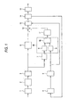
- Fig. 1 is a block diagram showing the configuration of a controller in example 1.
- a steering torque occurring when a driver performs steering is detected by a torque sensor 1, and an analog phase compensator 2 formed with an analog circuit improves a frequency characteristic so that a phase will lead at most at an oscillation frequency f vib .
- a torque sensor output, for which the frequency characteristic is improved is converted into a digital signal by an A/D converter 3, and fetched into a microcomputer.
- a current which drives a motor is detected by a current detector 4, converted into a digital signal by a current A/D converter 5, and fetched into the microcomputer.
- a torque controller 6 computes an auxiliary torque current using the torque sensor output for which the frequency characteristic is improved.
- a torque opposite phase compensator 7 computers an opposite characteristic of the analog phase compensator, and inputs the opposite characteristic to a first rotating speed estimator 18 (part of the drawing encircled with a dot line).
- the first rotating speed estimator 18 estimates or computes a motor rotating speed, which has a low-frequency component thereof cut by a motor rotation observer 10 (identical to a rotating speed observer, wherein the same applies to a description to be made below), using a signal produced by cutting a low-frequency component of the steering torque signal, for which the frequency characteristic is returned to a frequency characteristic equivalent to that for a phase-uncompensated steering torque, through high-pass filter computation performed by a torque HPF 8, and a signal produced by cutting a low frequency component of a current through high-pass filter computation performed by a current HPF 9.
- a damping controller 11 computes a damping current using the resultant estimated motor rotating speed, and an adder 12 adds up an auxiliary torque current and the damping current so as to perform target current computation.
- a current controller 13 controls a current so that the computed target current and a current detected by the current detector 4 will be squared with each other.
- the resultant current is output as a voltage command signal, for example, a PWM signal to a drive circuit 14, and a motor 15 is driven so that an assist torque will be generated.
- the motor rotation observer 10 that performs estimation computation of a motor rotating speed is, for example, an observer using as a model a single-degree-of-freedom oscillation equation that has an inertia moment of a motor as an inertial term and a spring constant of a torque sensor as a spring term (the same applies to a description to be made later).
- the rotating speed estimation means encompass as an example thereof the first rotating speed estimator.
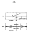
- a total characteristic that is a combination of the characteristic A of the analog phase compensator 2 and the characteristic B of the torque opposite phase compensator 7 shall be a characteristic C.
- a maximum frequency to be cut by a high-pass filter that is the torque HPF 8 (where HPF stands for a high-pass filter, wherein the same applies to a description to be made below) or the current HPF 9 is set to a frequency higher than 5 Hz that is a maximum frequency which a driver can support.
- a torque sensor output that is A/D-converted by the torque A/D converter 3 and is analog-phase-compensated is read and stored in a memory.
- the current A/D converter 5 reads an A/D-converted current detection value (identical to a current detector output, wherein the same applies to a description to be made below), and stores it in the memory.
- the torque controller 6 reads the torque sensor output, which is stored in the memory and is analog-phase-compensated, performs mapping computation on an auxiliary torque current, and stores the resultant current in the memory.
- the torque opposite phase compensator 7 reads the torque sensor output, which is stored in the memory and is analog-phase-compensated, performs opposite phase compensation computation, and stores the torque sensor output, which has undergone opposite phase compensation computation, in the memory.
- the torque HPF 8 performs high-pass filter computation on the torque sensor output that is stored in the memory and has undergone opposite phase compensation computation, and stores the torque sensor output, which is high-pass-filtered, in the memory.
- the current HPF 9 performs high-pass filter computation on the current detection value that is stored in the memory, and stores the current detection value, which is high-pass-filtered, in the memory.
- the motor rotation observer 10 performs motor rotating speed computation using the torque sensor output, which is stored in the memory and is high-pass-filtered, and the current detection value that is high-pass-filtered, and stores the result in the memory.
- the damping controller 11 computes a damping current by multiplying the motor rotating speed, which is stored in the memory, by a gain, and stores the damping current in the memory.
- the adder 12 adds up the auxiliary torque current and damping current so as to obtain a target current.
- the current controller 13 performs current control computation using the target current and current detection value, and outputs the result as a voltage command signal such as a PWM signal to the drive circuit 14.
- the processing from step S101 to step S110 is executed for every control sampling.
- a torque sensor signal that is needed for computation of an auxiliary torque current by the torque controller 6 and is analog-phase-compensated, and a torque sensor signal that is needed for computation by the motor rotation observer 10 and is not phase-compensated, can be obtained with the one torque A/D converter 3. Consequently, excellent oscillation suppression performance can be realized without an increase in cost.
- an electric signal to be input to the current HPF 9 is detected by the current detector 4, and a current detection value obtained by converting the current signal into a digital signal by the current A/D converter 5 is employed.
- a target current computed by the adder 12 may be employed.
- the example 2 is different from the example 1 in the software configuration of the torque opposite phase compensator 7. The difference alone will be described using Fig. 4 .
- the characteristic D of the torque opposite phase compensator 7 is approximated to the characteristic of the analog phase compensator 2.
- the damping controller 11 When computing a damping current, the damping controller 11 needs a highly precise motor rotating speed signal relative to a frequency at which steering wheel oscillations occur. Consequently, the motor rotation observer 10 needs a torque sensor output, which is devoid of a phase shift caused by the analog phase compensator 2, relative to the frequency at which the steering wheel oscillations occur.
- f a1 and f a2 are determined so that the range from f a1 to f a2 will include the frequency at which steering wheel oscillations occur, even when the torque opposite phase compensator is the low-pass filter that causes a gain to begin decreasing at f i1 , the total characteristic that is the combination of the characteristic A of the analog phase compensator 2 and the characteristic D of the torque opposite phase compensator 7 causes, as indicated with E, a gain to remain even and causes a phase shift to diminish. Consequently, a higher-precision motor rotating speed signal can be obtained than that obtained when the torque opposite phase compensator 7 is not included. As a result, the same steering wheel oscillation reduction effect as that of the example 1 can be realized.
- Fig. 5 is a block diagram showing the configuration of a controller according to the Embodiment of the invention.
- a torque phase lead reducer 16 is disposed on a stage succeeding the torque HPF 8 in a second rotating speed estimator 19, and a current phase lead reducer 17 is disposed on a stage succeeding the current HPF 9 therein.
- the characteristic F of the torque HPF 8 demonstrates, as shown in Fig. 6 , that a low-frequency component of a steering torque signal is cut at an oscillation occurrence frequency but the phase of the steering torque signal is caused to lead at a steering wheel oscillation frequency. Consequently, the torque phase lead reducer 16 having, as shown as a characteristic G in Fig. 7 , a low-pass filter characteristic that causes the ratio between the steering wheel oscillation frequency f vib and the cutoff frequency f T_HPF of the torque HPF 8 and the ratio between the cutoff frequency f T_comp of the torque phase lead reducer 16 and the steering wheel oscillation frequency f vib to be identical to each other is disposed on the stage succeeding the torque HPF 8. Moreover, the current phase lead reducer 17 having the same frequency characteristic as the torque phase lead reducer 16 is disposed on the stage succeeding the current HPF 9.
- the rotating speed estimation means encompass as an example thereof the second rotating speed estimator.
- a processing algorithm in the microcomputer of the embodiment will be described below in conjunction with the flowchart of Fig. 8 .
- a torque sensor output that is A/D-converted by the torque A/D converter 3 and is analog-phase-compensated is read and stored in the memory.
- a current detection value that is A/D-converted by the current A/D converter 5 is read and stored in the memory.
- the torque controller 6 reads the torque sensor output that is stored in the memory and is analog-phase-compensated, performs mapping computation on an auxiliary torque current, and stores the resultant current in the memory.
- the torque opposite phase compensator 7 reads the torque sensor output that is stored in the memory and is analog-phase-compensated, performs opposite phase compensation computation, and stores the torque sensor output, which has undergone opposite phase compensation computation, in the memory.
- the torque HPF 8 performs high-pass filter computation on the torque sensor output that is stored in the memory and has undergone opposite phase compensation computation, and stores the torque sensor output, which is high-pass-filtered, in the memory.
- the current HPF 9 performs high-pass filter computation on the current detection value that is stored in the memory, and stores the current detection value, which is high-pass-filtered, in the memory.
- the torque phase lead reducer 16 performs low-pass filter computation on the torque sensor output that is stored in the memory and is high-pass-filtered, and stores the torque sensor output, which is low-pass-filtered, in the memory.
- the current phase lead reducer 17 performs low-pass filter computation on the current detection value that is stored in the memory and is high-pass-filtered, and stores the current detection value, which is low-pass-filtered, in the memory.
- the motor rotation observer 10 performs motor rotating speed computation using the torque sensor output, which is stored in the memory and is low-pass-filtered, and the current detection value that is low-pass-filtered, and stores the result in the memory.
- the damping controller 11 performs damping current computation by multiplying the motor rotating speed, which is stored in the memory, by a gain, and stores the result in the memory.
- the adder 12 adds up an auxiliary torque current and a damping current so as to obtain a target current.
- the current controller 13 performs current control computation using the target current and current detection value, and outputs the result as a voltage command signal such as a PWM signal to the drive circuit 14.
- the processing from step S301 to step S312 is executed for every control sampling.
- a characteristic (total characteristic H in Fig. 9 ) that is a combination of the characteristic F of the torque HPF 8 and the characteristic G of the torque phase lead reducer 16 can be obtained.
- both a gain and a phase have a value of 0 at the steering wheel oscillation frequency f vib . Consequently, a shift can be eliminated, and the precision in the motor rotating speed signal improves. As a result, an excellent steering wheel oscillation reduction effect can be realized.
Description
- The invention relates to an electric power steering control system, in particular an electric power steering control system for automobiles.
- In electric power steering systems, an assist torque substantially proportional to a steering torque is determined. The steering torque of a driver of an automobile is reduced by increasing a torque proportional gain that corresponds to the proportional relationship. At this time, if the torque proportional gain is too large, a control system oscillates to bring about steering wheel oscillations. In some cases, the degree to which the steering torque is reduced is therefore restricted.
In order to solve this problem, an algorithm for suppressing oscillations by improving the phase characteristic of the control system through introduction of a phase compensator has been disclosed to prevent the steering wheel oscillations (refer to, for example, a Reference Literature 1). - For the purpose of improving oscillation suppression performance, in addition to the phase compensator, a control algorithm that suppresses oscillations by inferring an oscillation frequency component of a motor rotating speed from a steering torque signal and a current signal, which drives a motor, by means of an observer, and feeding back the oscillation frequency component has been disclosed to prevent steering wheel oscillations (refer to, for example, a Reference Literature 2).
- Reference Literature I:
-
JP-A-8-091 236 Fig. 1 ) - Reference Literature 2:
-
JP-A-2000-168 600 - In the electric power steering system, a majority of the control algorithm is constituted by software, the steering torque signal is fetched into a microcomputer through a torque signal converter, that is, an A/D conversion circuit, and then arithmetically processed. This is because the oscillation frequency in electric power steering is relatively low to range from 30 Hz to 100 Hz.
However, there are a case where the phase compensator alone included in the control algorithm is formed by software and the microcomputer is used for computation, and a case where an analog circuit directly performs phase compensation. When the microcomputer is used for computation, if the oscillation frequency of the control system is high, high-speed arithmetic processing is required. An expensive microcomputer is therefore needed. - When the analog circuit performs phase compensation, since a steering torque signal on which phase compensation is not performed is needed for the computation by the observer, both a steering torque signal on which phase compensation is performed by the analog circuit and a steering torque signal on which phase compensation is not performed have to be A/D-converted and fetched into the microcomputer. The number of required A/D conversion circuits therefore increases.
- As mentioned above, when the control algorithm that suppresses oscillations by inferring an oscillation frequency component of a motor rotating speed from a steering torque signal and a current signal, which drives a motor, by means of an observer, and feeding back the oscillation frequency component is used in addition to the phase compensator, whether the phase compensator is formed by an analog circuit or software, the cost increases.
- The invention is intended to solve the foregoing problems and to provide an electric power steering control system that realizes excellent oscillation suppression performance without increasing the number of A/D conversion circuits, that is, without incurring an increase of cost.
- According to the present invention, an electric power steering control system is disclosed which comprises:
- torque detection means that detect a steering torque caused by a driver;
- a torque controller that computes an auxiliary torque current, which assists the steering torque, using the output of the torque detection means;
- a motor that generates a torque which assists the steering torque;
- current detection means that detect a current value to be conducted to the motor;
- rotating speed estimation means that estimate the rotating speed of the motor; and
- a damping controller that computes a damping current, which is added to the auxiliary torque current, using the estimate value of the rotating speed of the motor estimated by the rotating speed estimation means.
- motor current steering component removal means that remove a component caused by steering from the output of the current detection means;
- torque steering component removal means that remove a component caused by steering from the output of the torque detection means; and
- a rotating speed observer that computes the estimate value of the rotating speed of the motor using the current which has the steering component thereof removed by the motor current steering component removal means, and the steering torque output from the torque steering component removal means; and
- at least one of a motor current phase lead reducer that diminishes a phase lead caused by the motor current steering component removal means, and a torque phase lead reducer that diminishes a phase lead caused by the torque steering component removal means.
- According to the invention, the phase compensator for a steering torque is formed with an analog circuit, and the opposite phase compensator is formed by software in the microcomputer. The changes in a gain and a phase caused by the phase compensator of an analog circuit are canceled at an oscillation frequency. A steering torque signal equivalent to a steering torque signal that is needed for computation by the observer and has not undergone phase compensation is computed from a steering torque signal having undergone phase compensation.
Since this obviates the necessity of A/D-converting the steering torque signal that has not undergone phase compensation, and fetching the resultant signal into a microcomputer, the number of A/D conversion circuits decreases. Eventually, excellent oscillation suppression performance can be realized without an increase of cost. -
- Fig. 1
- is a block diagram showing the configuration of a controller in an unclaimed example 1;
- Fig. 2
- includes Bode diagrams showing the frequency characteristics of an opposite phase compensator of the controller in the example 1;
- Fig. 3
- is a flowchart presenting processing to be performed in a microcomputer of the controller in the example 1;
- Fig. 4
- includes Bode diagrams showing the frequency characteristics of an opposite phase compensator of a controller in an unclaimed example 2;
- Fig. 5
- is a block diagram showing the configuration of a controller in the Embodiment ;
- Fig. 6
- includes Bode diagrams showing the frequency characteristics of a torque HPF of the controller in the Embodiment ;
- Fig. 7
- includes Bode diagrams showing the frequency characteristics of a torque phase lead reducer of the controller in the Embodiment ;
- Fig. 8
- is a flowchart presenting processing to be performed in a microcomputer of the controller in the Embodiment ; and
- Fig. 9
- includes Bode diagrams showing the frequency characteristics of a combination of a torque HPF and a torque phase lead reducer of the controller in the Embodiment .
-
- 1 =
- torque sensor
- 2 =
- analog phase compensator
- 3 =
- torque A/D converter
- 4 =
- current detector
- 5 =
- current A/D converter
- 6 =
- torque controller
- 7 =
- torque opposite phase compensator
- 8 =
- torque HPF
- 9 =
- current HPF
- 10 =
- motor rotation observer
- 11 =
- damping controller
- 12 =
- adder
- 13 =
- current controller
- 14 =
- drive circuit
- 15 =
- motor
- 16 =
- torque phase lead reducer
- 17 =
- current phase lead reducer
- 18 =
- first rotating speed estimator
- 19 =
- second rotating speed estimator
-
Fig. 1 is a block diagram showing the configuration of a controller in example 1. A steering torque occurring when a driver performs steering is detected by a torque sensor 1, and ananalog phase compensator 2 formed with an analog circuit improves a frequency characteristic so that a phase will lead at most at an oscillation frequency fvib.
A torque sensor output, for which the frequency characteristic is improved, is converted into a digital signal by an A/D converter 3, and fetched into a microcomputer. A current which drives a motor is detected by acurrent detector 4, converted into a digital signal by a current A/D converter 5, and fetched into the microcomputer.
In the microcomputer, atorque controller 6 computes an auxiliary torque current using the torque sensor output for which the frequency characteristic is improved. A torque opposite phase compensator 7 computers an opposite characteristic of the analog phase compensator, and inputs the opposite characteristic to a first rotating speed estimator 18 (part of the drawing encircled with a dot line).
The firstrotating speed estimator 18 estimates or computes a motor rotating speed, which has a low-frequency component thereof cut by a motor rotation observer 10 (identical to a rotating speed observer, wherein the same applies to a description to be made below), using a signal produced by cutting a low-frequency component of the steering torque signal, for which the frequency characteristic is returned to a frequency characteristic equivalent to that for a phase-uncompensated steering torque, through high-pass filter computation performed by atorque HPF 8, and a signal produced by cutting a low frequency component of a current through high-pass filter computation performed by acurrent HPF 9.
A dampingcontroller 11 computes a damping current using the resultant estimated motor rotating speed, and anadder 12 adds up an auxiliary torque current and the damping current so as to perform target current computation. Acurrent controller 13 controls a current so that the computed target current and a current detected by thecurrent detector 4 will be squared with each other. The resultant current is output as a voltage command signal, for example, a PWM signal to adrive circuit 14, and amotor 15 is driven so that an assist torque will be generated.
Herein, themotor rotation observer 10 that performs estimation computation of a motor rotating speed is, for example, an observer using as a model a single-degree-of-freedom oscillation equation that has an inertia moment of a motor as an inertial term and a spring constant of a torque sensor as a spring term (the same applies to a description to be made later). Moreover, in the invention, the rotating speed estimation means encompass as an example thereof the first rotating speed estimator. - As shown in
Fig. 2 , the characteristic B of the torque opposite phase compensator 7 is determined to be opposite to the characteristic A of theanalog phase compensator 2. Specifically, assuming that the characteristic A of theanalog phase compensator 2 causes a gain to increase within a frequency range from fa1 to fa2, fa1 = fi1 and fa2 = fi2 are established so that a frequency range from fi1 to fi2 within which the characteristic B of the torque opposite phase compensator 7 causes a gain to decrease will be identical to the frequency range from fa1 to fa2. A total characteristic that is a combination of the characteristic A of theanalog phase compensator 2 and the characteristic B of the torque opposite phase compensator 7 shall be a characteristic C.
Moreover, a maximum frequency to be cut by a high-pass filter that is the torque HPF 8 (where HPF stands for a high-pass filter, wherein the same applies to a description to be made below) or thecurrent HPF 9 is set to a frequency higher than 5 Hz that is a maximum frequency which a driver can support. - Next, a processing algorithm in the microcomputer in the example 1 will be described in conjunction with the flowchart of
Fig. 3 .
First, at step S101, a torque sensor output that is A/D-converted by the torque A/D converter 3 and is analog-phase-compensated is read and stored in a memory. At step S102, the current A/D converter 5 reads an A/D-converted current detection value (identical to a current detector output, wherein the same applies to a description to be made below), and stores it in the memory.
At step S103, thetorque controller 6 reads the torque sensor output, which is stored in the memory and is analog-phase-compensated, performs mapping computation on an auxiliary torque current, and stores the resultant current in the memory. At step S104, the torque opposite phase compensator 7 reads the torque sensor output, which is stored in the memory and is analog-phase-compensated, performs opposite phase compensation computation, and stores the torque sensor output, which has undergone opposite phase compensation computation, in the memory.
At step S105, thetorque HPF 8 performs high-pass filter computation on the torque sensor output that is stored in the memory and has undergone opposite phase compensation computation, and stores the torque sensor output, which is high-pass-filtered, in the memory. At step S106, thecurrent HPF 9 performs high-pass filter computation on the current detection value that is stored in the memory, and stores the current detection value, which is high-pass-filtered, in the memory.
At step S107, themotor rotation observer 10 performs motor rotating speed computation using the torque sensor output, which is stored in the memory and is high-pass-filtered, and the current detection value that is high-pass-filtered, and stores the result in the memory. At step S108, the dampingcontroller 11 computes a damping current by multiplying the motor rotating speed, which is stored in the memory, by a gain, and stores the damping current in the memory.
At step S109, theadder 12 adds up the auxiliary torque current and damping current so as to obtain a target current. At step S110, thecurrent controller 13 performs current control computation using the target current and current detection value, and outputs the result as a voltage command signal such as a PWM signal to thedrive circuit 14. The processing from step S101 to step S110 is executed for every control sampling. - According to the foregoing constitution, a torque sensor signal that is needed for computation of an auxiliary torque current by the
torque controller 6 and is analog-phase-compensated, and a torque sensor signal that is needed for computation by themotor rotation observer 10 and is not phase-compensated, can be obtained with the one torque A/D converter 3. Consequently, excellent oscillation suppression performance can be realized without an increase in cost. - In the present example, an electric signal to be input to the
current HPF 9 is detected by thecurrent detector 4, and a current detection value obtained by converting the current signal into a digital signal by the current A/D converter 5 is employed. Alternatively, a target current computed by theadder 12 may be employed. - The example 2 is different from the example 1 in the software configuration of the torque opposite phase compensator 7. The difference alone will be described using
Fig. 4 .
In the example 2, the characteristic D of the torque opposite phase compensator 7 is approximated to the characteristic of theanalog phase compensator 2. Specifically, assuming that the characteristic A of theanalog phase compensator 2 is a characteristic causing a gain to increase at a ratio of, for example, 20 dB/dec within a frequency range from fa1 to fa2, the torque opposite phase compensator 7 shall be a low-pass filter that causes a gain to begin decreasing at fi1 at the ratio of 20 dB/dec, and fa1 = fi1 is established.
When computing a damping current, the dampingcontroller 11 needs a highly precise motor rotating speed signal relative to a frequency at which steering wheel oscillations occur. Consequently, themotor rotation observer 10 needs a torque sensor output, which is devoid of a phase shift caused by theanalog phase compensator 2, relative to the frequency at which the steering wheel oscillations occur.
On the other hand, since fa1 and fa2 are determined so that the range from fa1 to fa2 will include the frequency at which steering wheel oscillations occur, even when the torque opposite phase compensator is the low-pass filter that causes a gain to begin decreasing at fi1, the total characteristic that is the combination of the characteristic A of theanalog phase compensator 2 and the characteristic D of the torque opposite phase compensator 7 causes, as indicated with E, a gain to remain even and causes a phase shift to diminish.
Consequently, a higher-precision motor rotating speed signal can be obtained than that obtained when the torque opposite phase compensator 7 is not included. As a result, the same steering wheel oscillation reduction effect as that of the example 1 can be realized. - According to the foregoing constitution, since a simple low-pass filter is employed, the necessity of computing a characteristic opposite to the characteristic of the
analog phase compensator 2 over a high-frequency domain over which high-speed arithmetic processing is required is obviated. Consequently, the foregoing effect can be realized despite an inexpensive microcomputer. -
Fig. 5 is a block diagram showing the configuration of a controller according to the Embodiment of the invention. In addition to the components of the example 1, a torquephase lead reducer 16 is disposed on a stage succeeding thetorque HPF 8 in a secondrotating speed estimator 19, and a currentphase lead reducer 17 is disposed on a stage succeeding thecurrent HPF 9 therein. - The characteristic F of the
torque HPF 8 demonstrates, as shown inFig. 6 , that a low-frequency component of a steering torque signal is cut at an oscillation occurrence frequency but the phase of the steering torque signal is caused to lead at a steering wheel oscillation frequency. Consequently, the torquephase lead reducer 16 having, as shown as a characteristic G inFig. 7 , a low-pass filter characteristic that causes the ratio between the steering wheel oscillation frequency fvib and the cutoff frequency fT_HPF of thetorque HPF 8 and the ratio between the cutoff frequency fT_comp of the torquephase lead reducer 16 and the steering wheel oscillation frequency fvib to be identical to each other is disposed on the stage succeeding thetorque HPF 8.
Moreover, the currentphase lead reducer 17 having the same frequency characteristic as the torquephase lead reducer 16 is disposed on the stage succeeding thecurrent HPF 9. In the invention, the rotating speed estimation means encompass as an example thereof the second rotating speed estimator. - Next, a processing algorithm in the microcomputer of the embodiment will be described below in conjunction with the flowchart of
Fig. 8 .
First, at step S301, a torque sensor output that is A/D-converted by the torque A/D converter 3 and is analog-phase-compensated is read and stored in the memory. At step S302, a current detection value that is A/D-converted by the current A/D converter 5 is read and stored in the memory.
At step S303, thetorque controller 6 reads the torque sensor output that is stored in the memory and is analog-phase-compensated, performs mapping computation on an auxiliary torque current, and stores the resultant current in the memory. At step S304, the torque opposite phase compensator 7 reads the torque sensor output that is stored in the memory and is analog-phase-compensated, performs opposite phase compensation computation, and stores the torque sensor output, which has undergone opposite phase compensation computation, in the memory.
At step S305, thetorque HPF 8 performs high-pass filter computation on the torque sensor output that is stored in the memory and has undergone opposite phase compensation computation, and stores the torque sensor output, which is high-pass-filtered, in the memory. At step S306, thecurrent HPF 9 performs high-pass filter computation on the current detection value that is stored in the memory, and stores the current detection value, which is high-pass-filtered, in the memory.
At step S307, the torquephase lead reducer 16 performs low-pass filter computation on the torque sensor output that is stored in the memory and is high-pass-filtered, and stores the torque sensor output, which is low-pass-filtered, in the memory. At step S308, the currentphase lead reducer 17 performs low-pass filter computation on the current detection value that is stored in the memory and is high-pass-filtered, and stores the current detection value, which is low-pass-filtered, in the memory.
At step S309, themotor rotation observer 10 performs motor rotating speed computation using the torque sensor output, which is stored in the memory and is low-pass-filtered, and the current detection value that is low-pass-filtered, and stores the result in the memory. At step S310, the dampingcontroller 11 performs damping current computation by multiplying the motor rotating speed, which is stored in the memory, by a gain, and stores the result in the memory.
At step S311, theadder 12 adds up an auxiliary torque current and a damping current so as to obtain a target current. At step 312, thecurrent controller 13 performs current control computation using the target current and current detection value, and outputs the result as a voltage command signal such as a PWM signal to thedrive circuit 14. The processing from step S301 to step S312 is executed for every control sampling. - According to the foregoing constitution, since the torque
phase lead reducer 16 is disposed in the stage succeeding thetorque HPF 8, a characteristic (total characteristic H inFig. 9 ) that is a combination of the characteristic F of thetorque HPF 8 and the characteristic G of the torquephase lead reducer 16 can be obtained. As seen from the total characteristic H inFig. 9 , both a gain and a phase have a value of 0 at the steering wheel oscillation frequency fvib. Consequently, a shift can be eliminated, and the precision in the motor rotating speed signal improves. As a result, an excellent steering wheel oscillation reduction effect can be realized.
wherein, the torque steering component removal means and the motor current steering removal means are formed as high-pass filters.
Claims (1)
- An electric power steering control system, comprising:- torque detection means (1) that detect a steering torque caused by a driver;- a torque controller (6) that computes an auxiliary torque current, which assists the steering torque, using the output of the torque detection means (1);- a motor (15) that generates a torque which assists the steering torque;- current detection means (4) that detect a current value to be conducted to the motor (15);- rotating speed estimation means (19) that estimate the rotating speed of the motor (15); and- a damping controller (11) that computes a damping current, which is added to the auxiliary torque current, using the estimate value of the rotating speed of the motor (15) estimated by the rotating speed estimation means (19),
wherein the rotating speed estimation means (19) include:- motor current steering component removal means (9) that remove a component caused by steering from the output of the current detection means (4);- torque steering component removal means (8) that remove a component caused by steering from the output of the torque detection means (1); and- a rotating speed observer (10) that computes the estimate value of the rotating speed of the motor (15) using the current which has the steering component thereof removed by the motor current steering component removal means (9), and the steering torque output from the torque steering component removal means (8);
characterized in that- at least one of a motor current phase lead reducer (17) that diminishes a phase lead caused by the motor current steering component removal means (9), and a torque phase lead reducer (16) that diminishes a phase lead caused by the torque steering component removal means (8) are present;- wherein the current phase lead reducer (17) has a low-pass filter characteristic causing the ratio between a steering wheel oscillation frequency and the cutoff frequency of the current steering component removal means (9), and the ratio between the cutoff frequency of the current phase lead reducer (17) and the steering wheel oscillation frequency to be identical to each other; and- wherein the torque phase lead reducer (16) has a low-pass filter characteristic causing the ratio between the steering wheel oscillation frequency and the cutoff frequency of the torque steering component removal means (8), and the ratio between the cutoff frequency of the torque phase lead reducer (16) and the steering wheel oscillation frequency to be identical to each other, and- wherein the torque steering component removal means (8) and the motor current steering removal means (9) are formed as high-pass filters.
Applications Claiming Priority (2)
| Application Number | Priority Date | Filing Date | Title |
|---|---|---|---|
| JP2006111239 | 2006-04-13 | ||
| EP07738312.3A EP2006188B1 (en) | 2006-04-13 | 2007-03-12 | Electric power steering control system |
Related Parent Applications (2)
| Application Number | Title | Priority Date | Filing Date |
|---|---|---|---|
| EP07738312.3 Division | 2007-03-12 | ||
| EP07738312.3A Division-Into EP2006188B1 (en) | 2006-04-13 | 2007-03-12 | Electric power steering control system |
Publications (2)
| Publication Number | Publication Date |
|---|---|
| EP2371676A1 EP2371676A1 (en) | 2011-10-05 |
| EP2371676B1 true EP2371676B1 (en) | 2013-09-04 |
Family
ID=38609135
Family Applications (2)
| Application Number | Title | Priority Date | Filing Date |
|---|---|---|---|
| EP07738312.3A Expired - Fee Related EP2006188B1 (en) | 2006-04-13 | 2007-03-12 | Electric power steering control system |
| EP11171670.0A Expired - Fee Related EP2371676B1 (en) | 2006-04-13 | 2007-03-12 | Electric power steering control system |
Family Applications Before (1)
| Application Number | Title | Priority Date | Filing Date |
|---|---|---|---|
| EP07738312.3A Expired - Fee Related EP2006188B1 (en) | 2006-04-13 | 2007-03-12 | Electric power steering control system |
Country Status (6)
| Country | Link |
|---|---|
| US (2) | US7983815B2 (en) |
| EP (2) | EP2006188B1 (en) |
| JP (2) | JP4767315B2 (en) |
| KR (1) | KR100984884B1 (en) |
| CN (1) | CN101395056B (en) |
| WO (1) | WO2007119333A1 (en) |
Families Citing this family (23)
| Publication number | Priority date | Publication date | Assignee | Title |
|---|---|---|---|---|
| US8612094B2 (en) * | 2008-03-12 | 2013-12-17 | Steering Solutions Ip Holding Corporation | Systems and methods involving velocity dependent damping |
| US8346435B2 (en) * | 2008-04-04 | 2013-01-01 | Mitsubishi Electric Corporation | Motor-driven power steering control device |
| CN102066182B (en) * | 2008-07-30 | 2012-11-28 | 三菱电机株式会社 | Motor-driven power steering control device |
| JP4807422B2 (en) * | 2009-03-09 | 2011-11-02 | 株式会社デンソー | Electric power steering system |
| DE102010031211A1 (en) * | 2010-07-12 | 2012-01-12 | Zf Lenksysteme Gmbh | Method and device for compensation of steering wheel torsional vibrations in a steering system |
| US8862324B2 (en) * | 2011-03-07 | 2014-10-14 | Steering Solutions Ip Holding Corporation | Damping methods and systems for electric power steering |
| CN103596828B (en) * | 2011-06-28 | 2017-10-17 | 舍弗勒技术股份两合公司 | The hybrid drivetrain of torsional vibration damper with active and for the method for the torsional vibration damper for implementing active |
| JP5760086B2 (en) * | 2011-08-04 | 2015-08-05 | 本田技研工業株式会社 | Electric power steering device |
| US9278709B2 (en) * | 2011-12-12 | 2016-03-08 | Steering Solutions Ip Holding Corporation | Steering system having compensation command calibration |
| JP5835091B2 (en) * | 2012-05-11 | 2015-12-24 | 日本精工株式会社 | Electric power steering device |
| JP6378887B2 (en) * | 2014-02-04 | 2018-08-22 | Kyb株式会社 | Electric power steering device |
| CN106232459B (en) * | 2014-04-21 | 2018-06-15 | 三菱电机株式会社 | Electric power-assisted steering apparatus |
| CN105882736A (en) * | 2014-12-16 | 2016-08-24 | 重庆邮电大学 | Damping control method for vehicle electric power steering system |
| CN107210692B (en) | 2015-02-10 | 2020-04-07 | 皮尔伯格泵技术有限责任公司 | Electric vehicle auxiliary unit and method for reversing vehicle auxiliary unit |
| US10399597B2 (en) | 2015-10-09 | 2019-09-03 | Steering Solutions Ip Holding Corporation | Payload estimation using electric power steering signals |
| US10569801B2 (en) | 2015-10-09 | 2020-02-25 | Steering Solutions Ip Holding Corporation | Payload estimation using electric power steering signals |
| CN109476338B (en) * | 2016-09-20 | 2022-03-15 | 克诺尔转向系统日本有限公司 | Power steering apparatus |
| KR102330546B1 (en) * | 2017-07-28 | 2021-11-25 | 현대모비스 주식회사 | Apparatus for reducing vibration of motor driven power steering and method thereof |
| JP7005402B2 (en) * | 2018-03-20 | 2022-02-04 | 日立Astemo株式会社 | Power steering device control device |
| US11511790B2 (en) | 2019-02-14 | 2022-11-29 | Steering Solutions Ip Holding Corporation | Road friction coefficient estimation using steering system signals |
| US11498613B2 (en) | 2019-02-14 | 2022-11-15 | Steering Solutions Ip Holding Corporation | Road friction coefficient estimation using steering system signals |
| US11407442B2 (en) * | 2019-07-31 | 2022-08-09 | Steering Solutions Ip Holding Corporation | Steer-by-wire system |
| JP7339204B2 (en) | 2020-04-15 | 2023-09-05 | トヨタ自動車株式会社 | steering control system |
Family Cites Families (11)
| Publication number | Priority date | Publication date | Assignee | Title |
|---|---|---|---|---|
| JP3129334B2 (en) | 1991-10-11 | 2001-01-29 | 三菱重工業株式会社 | Active dynamic damper control device |
| JPH05155352A (en) | 1991-12-02 | 1993-06-22 | Omron Corp | Electromotive power steering device |
| KR970005786B1 (en) * | 1992-04-27 | 1997-04-21 | 미쓰비시덴키 가부시키가이샤 | Motor assisted power steering control device |
| JPH0891236A (en) | 1994-09-21 | 1996-04-09 | Honda Motor Co Ltd | Motor driven power steering device |
| JP3712876B2 (en) * | 1998-12-01 | 2005-11-02 | 三菱電機株式会社 | Electric power steering control device |
| US6122579A (en) * | 1999-05-28 | 2000-09-19 | Delphi Technologies, Inc. | Electric power steering control with torque ripple and road disturbance damper |
| JP2003081102A (en) * | 2001-09-12 | 2003-03-19 | Koyo Seiko Co Ltd | Electric power steering device |
| JP2005065443A (en) * | 2003-08-18 | 2005-03-10 | Koyo Seiko Co Ltd | Electric power steering device |
| US6863150B1 (en) * | 2003-09-25 | 2005-03-08 | Mitsubishi Denki Kabushiki Kaisha | Electric power steering control apparatus |
| JP4415791B2 (en) | 2004-08-24 | 2010-02-17 | 三菱電機株式会社 | Electric power steering control device |
| US8346435B2 (en) * | 2008-04-04 | 2013-01-01 | Mitsubishi Electric Corporation | Motor-driven power steering control device |
-
2007
- 2007-03-12 EP EP07738312.3A patent/EP2006188B1/en not_active Expired - Fee Related
- 2007-03-12 EP EP11171670.0A patent/EP2371676B1/en not_active Expired - Fee Related
- 2007-03-12 KR KR1020087017781A patent/KR100984884B1/en active IP Right Grant
- 2007-03-12 CN CN2007800072385A patent/CN101395056B/en not_active Expired - Fee Related
- 2007-03-12 US US12/160,438 patent/US7983815B2/en not_active Expired - Fee Related
- 2007-03-12 WO PCT/JP2007/054840 patent/WO2007119333A1/en active Application Filing
- 2007-03-12 JP JP2008510762A patent/JP4767315B2/en not_active Expired - Fee Related
-
2010
- 2010-12-07 US US12/962,191 patent/US8019507B2/en not_active Expired - Fee Related
-
2011
- 2011-03-10 JP JP2011052757A patent/JP5355610B2/en active Active
Also Published As
| Publication number | Publication date |
|---|---|
| EP2371676A1 (en) | 2011-10-05 |
| US20110137525A1 (en) | 2011-06-09 |
| EP2006188A4 (en) | 2009-08-19 |
| KR100984884B1 (en) | 2010-10-04 |
| JPWO2007119333A1 (en) | 2009-08-27 |
| JP2011147343A (en) | 2011-07-28 |
| EP2006188A2 (en) | 2008-12-24 |
| KR20080085178A (en) | 2008-09-23 |
| EP2006188A9 (en) | 2009-07-22 |
| CN101395056A (en) | 2009-03-25 |
| WO2007119333A1 (en) | 2007-10-25 |
| US7983815B2 (en) | 2011-07-19 |
| JP4767315B2 (en) | 2011-09-07 |
| US8019507B2 (en) | 2011-09-13 |
| JP5355610B2 (en) | 2013-11-27 |
| US20100235047A1 (en) | 2010-09-16 |
| CN101395056B (en) | 2010-07-21 |
| EP2006188B1 (en) | 2015-02-25 |
Similar Documents
| Publication | Publication Date | Title |
|---|---|---|
| EP2371676B1 (en) | Electric power steering control system | |
| US8423245B2 (en) | Electric power steering control apparatus | |
| EP1878638B1 (en) | Control apparatus for electric power steering | |
| EP2213546B1 (en) | Steering control device | |
| EP1077171B1 (en) | Electric power steering controller and control method thereof | |
| US9254862B2 (en) | Electric power steering control device | |
| JP6164371B2 (en) | Electric power steering device | |
| EP2289767B1 (en) | Stability-based steering control methods and systems | |
| EP2269892B1 (en) | Motor-driven power steering control device | |
| EP1627797B1 (en) | Electric power steering device controller | |
| JP4134158B2 (en) | Electric power steering control device | |
| EP2266862A2 (en) | Electric power steering system | |
| JP2008296877A (en) | Electric power steering device | |
| EP2567881B1 (en) | Inertia compensation with frequency dependent damping | |
| CN114537509B (en) | Apparatus and method for controlling motor-driven power steering system | |
| JP4788160B2 (en) | Electric power steering device | |
| JP2003019974A (en) | Electric power steering device | |
| JP5734399B2 (en) | Electric power steering device | |
| JP5122258B2 (en) | Electric power steering control device | |
| JP5748827B2 (en) | Electric power steering device | |
| JP2006062390A (en) | Electric power steering control device and its control method | |
| JP2011063265A (en) | Electric power steering system | |
| JP2011088486A (en) | Electric power steering device |
Legal Events
| Date | Code | Title | Description |
|---|---|---|---|
| PUAI | Public reference made under article 153(3) epc to a published international application that has entered the european phase |
Free format text: ORIGINAL CODE: 0009012 |
|
| AC | Divisional application: reference to earlier application |
Ref document number: 2006188 Country of ref document: EP Kind code of ref document: P |
|
| AK | Designated contracting states |
Kind code of ref document: A1 Designated state(s): DE FR |
|
| 17P | Request for examination filed |
Effective date: 20120404 |
|
| 17Q | First examination report despatched |
Effective date: 20120614 |
|
| GRAP | Despatch of communication of intention to grant a patent |
Free format text: ORIGINAL CODE: EPIDOSNIGR1 |
|
| GRAS | Grant fee paid |
Free format text: ORIGINAL CODE: EPIDOSNIGR3 |
|
| GRAA | (expected) grant |
Free format text: ORIGINAL CODE: 0009210 |
|
| AC | Divisional application: reference to earlier application |
Ref document number: 2006188 Country of ref document: EP Kind code of ref document: P |
|
| AK | Designated contracting states |
Kind code of ref document: B1 Designated state(s): DE FR |
|
| REG | Reference to a national code |
Ref country code: DE Ref legal event code: R096 Ref document number: 602007032757 Country of ref document: DE Effective date: 20131031 |
|
| REG | Reference to a national code |
Ref country code: DE Ref legal event code: R097 Ref document number: 602007032757 Country of ref document: DE |
|
| PLBE | No opposition filed within time limit |
Free format text: ORIGINAL CODE: 0009261 |
|
| STAA | Information on the status of an ep patent application or granted ep patent |
Free format text: STATUS: NO OPPOSITION FILED WITHIN TIME LIMIT |
|
| 26N | No opposition filed |
Effective date: 20140605 |
|
| REG | Reference to a national code |
Ref country code: DE Ref legal event code: R097 Ref document number: 602007032757 Country of ref document: DE Effective date: 20140605 |
|
| REG | Reference to a national code |
Ref country code: FR Ref legal event code: PLFP Year of fee payment: 10 |
|
| REG | Reference to a national code |
Ref country code: DE Ref legal event code: R084 Ref document number: 602007032757 Country of ref document: DE |
|
| REG | Reference to a national code |
Ref country code: FR Ref legal event code: PLFP Year of fee payment: 11 |
|
| REG | Reference to a national code |
Ref country code: FR Ref legal event code: PLFP Year of fee payment: 12 |
|
| PGFP | Annual fee paid to national office [announced via postgrant information from national office to epo] |
Ref country code: DE Payment date: 20220203 Year of fee payment: 16 |
|
| PGFP | Annual fee paid to national office [announced via postgrant information from national office to epo] |
Ref country code: FR Payment date: 20220209 Year of fee payment: 16 |
|
| REG | Reference to a national code |
Ref country code: DE Ref legal event code: R119 Ref document number: 602007032757 Country of ref document: DE |
|
| PG25 | Lapsed in a contracting state [announced via postgrant information from national office to epo] |
Ref country code: FR Free format text: LAPSE BECAUSE OF NON-PAYMENT OF DUE FEES Effective date: 20230331 Ref country code: DE Free format text: LAPSE BECAUSE OF NON-PAYMENT OF DUE FEES Effective date: 20231003 |