EP2371502A1 - Multifunctional machining head - Google Patents
Multifunctional machining head Download PDFInfo
- Publication number
- EP2371502A1 EP2371502A1 EP11160871A EP11160871A EP2371502A1 EP 2371502 A1 EP2371502 A1 EP 2371502A1 EP 11160871 A EP11160871 A EP 11160871A EP 11160871 A EP11160871 A EP 11160871A EP 2371502 A1 EP2371502 A1 EP 2371502A1
- Authority
- EP
- European Patent Office
- Prior art keywords
- supporting structure
- central portion
- longitudinal direction
- unit
- machining
- Prior art date
- Legal status (The legal status is an assumption and is not a legal conclusion. Google has not performed a legal analysis and makes no representation as to the accuracy of the status listed.)
- Withdrawn
Links
- 238000003754 machining Methods 0.000 title claims description 49
- 230000008878 coupling Effects 0.000 claims description 2
- 238000010168 coupling process Methods 0.000 claims description 2
- 238000005859 coupling reaction Methods 0.000 claims description 2
- 239000007769 metal material Substances 0.000 claims description 2
- 230000003134 recirculating effect Effects 0.000 claims description 2
- 239000002023 wood Substances 0.000 description 8
- 238000005553 drilling Methods 0.000 description 5
- 239000000463 material Substances 0.000 description 4
- 238000003801 milling Methods 0.000 description 4
- 230000000694 effects Effects 0.000 description 2
- 230000005540 biological transmission Effects 0.000 description 1
Images


Classifications
-
- B—PERFORMING OPERATIONS; TRANSPORTING
- B27—WORKING OR PRESERVING WOOD OR SIMILAR MATERIAL; NAILING OR STAPLING MACHINES IN GENERAL
- B27C—PLANING, DRILLING, MILLING, TURNING OR UNIVERSAL MACHINES FOR WOOD OR SIMILAR MATERIAL
- B27C9/00—Multi-purpose machines; Universal machines; Equipment therefor
- B27C9/04—Multi-purpose machines; Universal machines; Equipment therefor with a plurality of working spindles
-
- B—PERFORMING OPERATIONS; TRANSPORTING
- B23—MACHINE TOOLS; METAL-WORKING NOT OTHERWISE PROVIDED FOR
- B23Q—DETAILS, COMPONENTS, OR ACCESSORIES FOR MACHINE TOOLS, e.g. ARRANGEMENTS FOR COPYING OR CONTROLLING; MACHINE TOOLS IN GENERAL CHARACTERISED BY THE CONSTRUCTION OF PARTICULAR DETAILS OR COMPONENTS; COMBINATIONS OR ASSOCIATIONS OF METAL-WORKING MACHINES, NOT DIRECTED TO A PARTICULAR RESULT
- B23Q39/00—Metal-working machines incorporating a plurality of sub-assemblies, each capable of performing a metal-working operation
- B23Q39/02—Metal-working machines incorporating a plurality of sub-assemblies, each capable of performing a metal-working operation the sub-assemblies being capable of being brought to act at a single operating station
- B23Q39/021—Metal-working machines incorporating a plurality of sub-assemblies, each capable of performing a metal-working operation the sub-assemblies being capable of being brought to act at a single operating station with a plurality of toolheads per workholder, whereby the toolhead is a main spindle, a multispindle, a revolver or the like
- B23Q39/022—Metal-working machines incorporating a plurality of sub-assemblies, each capable of performing a metal-working operation the sub-assemblies being capable of being brought to act at a single operating station with a plurality of toolheads per workholder, whereby the toolhead is a main spindle, a multispindle, a revolver or the like with same working direction of toolheads on same workholder
- B23Q39/024—Metal-working machines incorporating a plurality of sub-assemblies, each capable of performing a metal-working operation the sub-assemblies being capable of being brought to act at a single operating station with a plurality of toolheads per workholder, whereby the toolhead is a main spindle, a multispindle, a revolver or the like with same working direction of toolheads on same workholder consecutive working of toolheads
-
- B—PERFORMING OPERATIONS; TRANSPORTING
- B27—WORKING OR PRESERVING WOOD OR SIMILAR MATERIAL; NAILING OR STAPLING MACHINES IN GENERAL
- B27M—WORKING OF WOOD NOT PROVIDED FOR IN SUBCLASSES B27B - B27L; MANUFACTURE OF SPECIFIC WOODEN ARTICLES
- B27M1/00—Working of wood not provided for in subclasses B27B - B27L, e.g. by stretching
- B27M1/08—Working of wood not provided for in subclasses B27B - B27L, e.g. by stretching by multi-step processes
Definitions
- the invention refers to an operating unit of multifunctional type.
- the invention relates to an operating unit provided with several tool-holding spindles with which it is possible to associate tools that are suitable for various machinings, such as, for example, milling units, drills, multiple drilling heads, disc blades, etc.
- the multifunctional operating unit can be used in a numerical control machining centre for machining products made of wood or of material that is similar to wood.
- the prior art comprises the patent IT 1216860 that discloses a squaring edgebanding machine for machining wood, with multiple tool-holding spindles, having a multifunctional operating unit for machining the lower and upper surfaces near the edge of a workpiece; this operating unit comprises at least two spindles, each of which carries a machining tool; the operating unit is rotatably supported around a pin with the axes of the tool-holding spindles that extend radially with respect to the axis of the pin; the tools are brought to the machining position by rotation of the operating unit around the pin.
- An object of the invention is to make a multifunctional operating unit that is able to improve one or more of the aforesaid aspects of prior art multifunctional operating units.
- An advantage of the multifunctional operating unit is that it withstands great loads.
- An advantage of the multifunctional operating unit is that the deformation of the multifunctional operating unit is minimised.
- An advantage is to provide a multifunctional operating unit of reduced dimensions.
- An advantage is to provide an operating unit which is constructionally simple and cheap.
- An advantage is to provide a good quality multifunctional operating unit that is able to make products made of wood or material that is similar to wood.
- the machine can be set up, in particular, to produce windows and doors in general, that are made of wood or similar material.
- the numerically controlled machine will be provided with multi-axis movements.
- the numerical control machine is of known type and will not therefore be disclosed in greater detail.
- the operating unit 1 is configured for performing several operations, for example for milling, for drilling, for cutting, etc, by using various, possibly interchangeable, tools, which are operationally associable with various spindles.
- the multifunctional operating unit 1 comprises a supporting structure extended in a longitudinal direction, that can in be a vertical direction in use.
- the supporting structure can be constituted by a monobloc made of metallic material.
- the supporting structure has a central portion 2 and two lateral protruding portions 3 and 4 that protrude in a transverse (in use, horizontal) direction from two opposite sides F of the central portion 2.
- the supporting structure is (stiffly) connected to a portion of frame set up (in known manner) for attachment to a carriage or other movable element of the machine.
- the unit 1 has a first axial sliding guide 5 extending in the longitudinal direction and fixed for at least the greater part of the axial extent thereof (in the specific case, for the entire length thereof), in contact with a first surface 6 of a (vertical) supporting structure arranged on the first lateral protruding portion 3.
- the unit 1 comprises a first machining unit 7 that has a first tool-holding spindle 8.
- the first machining unit 7 is slidably coupled with the first sliding guide 5 with the possibility of moving in the longitudinal direction.
- the first axial sliding guide 5 is supported, in a continuous contact relationship, by a stiff surface of the supporting structure for at least one guide portion in which the stroke of the first machining unit 7 is provided; in particular, the first guide 5 has no parts affected by the stroke of the first unit 7 (and which are thus mechanically stressed by the passage of the first unit 7) and which protrude in a cantilevered manner from the supporting structure or are anyway devoid of a stiff support, supplied by the supporting structure, that is able to oppose the stress supplied by the first unit 7.
- the unit 1 has a second axial sliding guide 5' extending in the longitudinal direction and fixed, at least for the greater part of the axial extension thereof (in the specific case for the entire length thereof), in contact with a second surface 6' of the supporting structure arranged on the second lateral protruding portion 4.
- a second machining unit 7' has a second tool-holding spindle 8' and is slidingly coupled with the second sliding guide 5' with the possibility of moving in a longitudinal direction.
- the second axial sliding guide 5' is supported, in a continuous contact relationship, by a stiff surface of the supporting structure at least for one guide portion in which the stroke of the second machining unit 7' is provided; in particular, the guide 5' does not have parts that are affected by the stroke of the unit 7' (and which are thus mechanically stressed by the passage of the unit 7') and which protrude in a cantilevered manner from the supporting structure or are devoid of a stiff support, supplied by the supporting structure, that is able to oppose the stress supplied by the unit 7'.
- a third axial sliding guide 5" extends in the longitudinal direction and is fixed, at least for the greater part of the axial extent thereof, or, as in the specific case, for the entire length thereof, in contact with a third surface 6" of the supporting structure arranged on a first end of the central portion 2.
- the third surface of the supporting structure is arranged transversely (perpendicularly) to the two opposite sides F of the central portion 2.
- first and the second surfaces 6 and 6' of the supporting structure both face a first side of the unit 1, whilst the third surface 6" of the supporting structure faces a second side of the unit opposite the first side.
- a third machining unit 7" has a third tool-holding spindle 8" and is slidingly coupled with the third sliding guide 5" with the possibility of moving in the longitudinal direction.
- the third axial sliding guide 5" is supported, in a continuous contact relationship, by a stiff surface of the supporting structure at least for a guide portion in which the stroke of the second machining unit 7" is provided; in particular, the third guide 5" does not have parts that are affected by the stroke of the third unit 7" (and which are thus significantly mechanically stressed by the effect of the passage of the third machining unit 7") and which protrude in a cantilevered manner from the supporting structure or are anyway devoid of a stiff support, provided by the supporting structure, that is able to oppose the stress supplied by the third machining unit 7".
- a fourth axial sliding guide 5"' extends in the longitudinal direction and is fixed, at least for most of the axial extent thereof, or, as in the specific case, for the entire length thereof, in contact with a fourth surface 6"' of the supporting structure arranged on a second end of the central portion.
- the aforesaid second end is opposite the aforesaid first end.
- the two lateral portions 3 and 4 protrude from the first end.
- the fourth surface 6" of the supporting structure is arranged transversely (perpendicularly) to the aforesaid two sides F opposite the central portion 2.
- the fourth surface 6"' of the supporting structure faces the aforesaid first side of the unit.
- a fourth machining unit 7"' has a fourth tool-holding spindle 8"' and is slidingly coupled with the fourth sliding guide 5"' with the possibility of movement in the longitudinal direction.
- the fourth axial sliding guide 5"' is supported, in a continuous contact relationship, by a stiff surface of the supporting structure at least for a guide portion in which the stroke of the fourth machining unit 7"' is provided; in particular the fourth guide 5"' does not have parts that are affected by the stroke of the fourth unit 7"' (and which are thus mechanically stressed by the effect of the passage of the fourth machining unit 7"') and which protrude in a cantilevered manner from the supporting structure or are anyway devoid of a stiff support, provided by the supporting structure, that is able to oppose the stress supplied by the fourth machining unit 7"'.
- the first, second, third and fourth sliding guides 5, 5', 5" and 5"' each comprise a prismatic guide with a coupling of the recirculating revolving elements (balls and/or rollers) type.
- the first machining unit 7 can be associated, as in the specific example, with a disc blade.
- the second machining unit 7' can be associated, for example, with a vertical-axis tool (for example a milling and/or drilling tool).
- the third and fourth machining units 7" and 7"' can be associated in particular with two respective and different milling units with a horizontal axis.
- the first machining unit 7 is arranged in a first zone facing a side F of a central portion 2 and the second machining unit 7' is arranged in a second zone facing the other side F of central portion.
- the third machining unit 7" partially faces the third surface 6" of the supporting structure and partially faces a lower surface of the central portion 2.
- the aforesaid lower surface join together the third and fourth surfaces 6" and 6"' of the supporting structure and moreover joins together the two opposite sides F of the central portion 2.
- the fourth machining unit 7"' partially faces the fourth surface 6"' of the supporting structure and partially faces the aforesaid lower surface.
- the various spindles 8, 8', 8" and 8"' of the operating unit can be of various types and be intended to carry different types of tool.
- the first spindle 8 has a rotation axis (which in the specific case is horizontal) that is perpendicular to the longitudinal direction and transverse to the two opposite sides of the central portion 2.
- the second spindle 8' has a (vertical) rotation axis parallel to the longitudinal direction.
- the third and fourth spindles 8" and 8"' each have a (horizontal) rotation axis that is perpendicular to the longitudinal direction and transverse to the two opposite sides of the central portion 2.
- each of the aforesaid axial sliding guides 5, 5', 5" and 5"' does not have any end operating portion that protrudes in a cantilevered manner from the supporting structure, where as operating portion is intended a portion that exerts a guiding action on a respective movable machining unit.
- the central portion 2 has a plurality of longitudinal through holes that are parallel (vertical) to one another, each of which housing an element (the various elements have been indicated overall by 10) of elongated shape, a stem or shaft, that is movable in a longitudinal direction and connects a machining unit to driving means that are known and not disclosed in detail, that are arranged in the upper part of the operating unit.
- the elements 10 of elongated shape can be used, for example, to transmit to the machining unit the movement in a longitudinal direction and/or the machining energy for the tool.
- holes are present that house two groups (for example triads) of elements 10 of elongated shape that are respectively connected to the third and to the fourth machining units 7" and 7"'.
- the multifunctional operating unit can further comprise, as in the illustrated example, a multiple drilling head 11 (preset for holes with a vertical axis) situated at least partially below the lower surface of the central portion 2 of the supporting structure.
- the multiple drilling head 11 is connected to driving means, which is arranged in the upper part of the unit, by a transmission system arranged at least partially in one or more holes obtained inside the central portion 2.
- the head 11 is arranged in a central zone of the unit that is externally bounded, or surrounded, by the four machining units 7, 7', 7" and 7"'.
Landscapes
- Life Sciences & Earth Sciences (AREA)
- Engineering & Computer Science (AREA)
- Mechanical Engineering (AREA)
- Wood Science & Technology (AREA)
- Forests & Forestry (AREA)
- Nitrogen And Oxygen Or Sulfur-Condensed Heterocyclic Ring Systems (AREA)
- Switches With Compound Operations (AREA)
- Nitrogen Condensed Heterocyclic Rings (AREA)
- Machine Tool Units (AREA)
Abstract
Description
- The invention refers to an operating unit of multifunctional type.
- In particular, the invention relates to an operating unit provided with several tool-holding spindles with which it is possible to associate tools that are suitable for various machinings, such as, for example, milling units, drills, multiple drilling heads, disc blades, etc.
- Specifically, but not exclusively, the multifunctional operating unit can be used in a numerical control machining centre for machining products made of wood or of material that is similar to wood.
- The prior art comprises the patent
IT 1216860 - Some aspects of the multifunctional operating units of the prior art are improvable.
- In the first place, the operational flexibility of known multifunctional operating units is improvable, in particular the capacity thereof to perform a multiplicity of operations in the same compact structure.
- The strength and stiffness of known multifunctional operating units are also improvable, and, in particular, the capacity thereof to withstand great loads and minimise deformation.
- An object of the invention is to make a multifunctional operating unit that is able to improve one or more of the aforesaid aspects of prior art multifunctional operating units.
- An advantage of the multifunctional operating unit is that it withstands great loads.
- An advantage of the multifunctional operating unit is that the deformation of the multifunctional operating unit is minimised.
- An advantage is to provide a multifunctional operating unit of reduced dimensions.
- An advantage is to provide an operating unit which is constructionally simple and cheap.
- An advantage is to provide a good quality multifunctional operating unit that is able to make products made of wood or material that is similar to wood.
- Such aims and advantages and still others are all achieved by the operating unit according to one or more of the claims set out below.
- The invention can be better understood and implemented with reference to the attached drawings that show an embodiment thereof by way of non-limiting example.
-
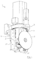
Figure 1 is a frontal perspective view of an embodiment of the operating unit according to the invention. -
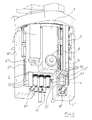
Figure 2 is a rear perspective view of the operating unit infigure 1 . -
Figure 3 is an enlarged frontal perspective view of the operating unit infigure 1 with certain parts removed to show other parts more clearly. -
Figure 4 is a bottom plan view of the operating unit infigure 1 . - With reference to the aforesaid figures, with 1 has been indicated overall a multifunctional operating unit that is intended for use in a numerical control machine for machining workpieces made of wood or of material that is similar to wood.
- The machine can be set up, in particular, to produce windows and doors in general, that are made of wood or similar material. The numerically controlled machine will be provided with multi-axis movements. The numerical control machine is of known type and will not therefore be disclosed in greater detail.
- The operating unit 1 is configured for performing several operations, for example for milling, for drilling, for cutting, etc, by using various, possibly interchangeable, tools, which are operationally associable with various spindles.
- The multifunctional operating unit 1 comprises a supporting structure extended in a longitudinal direction, that can in be a vertical direction in use. The supporting structure can be constituted by a monobloc made of metallic material. The supporting structure has a
central portion 2 and two lateral protrudingportions central portion 2. The supporting structure is (stiffly) connected to a portion of frame set up (in known manner) for attachment to a carriage or other movable element of the machine. - The unit 1 has a first axial
sliding guide 5 extending in the longitudinal direction and fixed for at least the greater part of the axial extent thereof (in the specific case, for the entire length thereof), in contact with afirst surface 6 of a (vertical) supporting structure arranged on the firstlateral protruding portion 3. The unit 1 comprises afirst machining unit 7 that has a first tool-holding spindle 8. Thefirst machining unit 7 is slidably coupled with the first slidingguide 5 with the possibility of moving in the longitudinal direction. - The first axial sliding
guide 5 is supported, in a continuous contact relationship, by a stiff surface of the supporting structure for at least one guide portion in which the stroke of thefirst machining unit 7 is provided; in particular, thefirst guide 5 has no parts affected by the stroke of the first unit 7 (and which are thus mechanically stressed by the passage of the first unit 7) and which protrude in a cantilevered manner from the supporting structure or are anyway devoid of a stiff support, supplied by the supporting structure, that is able to oppose the stress supplied by thefirst unit 7. - The unit 1 has a second axial sliding guide 5' extending in the longitudinal direction and fixed, at least for the greater part of the axial extension thereof (in the specific case for the entire length thereof), in contact with a second surface 6' of the supporting structure arranged on the second
lateral protruding portion 4. A second machining unit 7' has a second tool-holding spindle 8' and is slidingly coupled with the second sliding guide 5' with the possibility of moving in a longitudinal direction. - The second axial sliding guide 5' is supported, in a continuous contact relationship, by a stiff surface of the supporting structure at least for one guide portion in which the stroke of the second machining unit 7' is provided; in particular, the guide 5' does not have parts that are affected by the stroke of the unit 7' (and which are thus mechanically stressed by the passage of the unit 7') and which protrude in a cantilevered manner from the supporting structure or are devoid of a stiff support, supplied by the supporting structure, that is able to oppose the stress supplied by the unit 7'.
- A third axial
sliding guide 5" extends in the longitudinal direction and is fixed, at least for the greater part of the axial extent thereof, or, as in the specific case, for the entire length thereof, in contact with athird surface 6" of the supporting structure arranged on a first end of thecentral portion 2. The third surface of the supporting structure is arranged transversely (perpendicularly) to the two opposite sides F of thecentral portion 2. - In the specific case, the first and the
second surfaces 6 and 6' of the supporting structure both face a first side of the unit 1, whilst thethird surface 6" of the supporting structure faces a second side of the unit opposite the first side. - A
third machining unit 7" has a third tool-holding spindle 8" and is slidingly coupled with the third slidingguide 5" with the possibility of moving in the longitudinal direction. The third axial slidingguide 5" is supported, in a continuous contact relationship, by a stiff surface of the supporting structure at least for a guide portion in which the stroke of thesecond machining unit 7" is provided; in particular, thethird guide 5" does not have parts that are affected by the stroke of thethird unit 7" (and which are thus significantly mechanically stressed by the effect of the passage of thethird machining unit 7") and which protrude in a cantilevered manner from the supporting structure or are anyway devoid of a stiff support, provided by the supporting structure, that is able to oppose the stress supplied by thethird machining unit 7". - A fourth axial
sliding guide 5"' extends in the longitudinal direction and is fixed, at least for most of the axial extent thereof, or, as in the specific case, for the entire length thereof, in contact with afourth surface 6"' of the supporting structure arranged on a second end of the central portion. The aforesaid second end is opposite the aforesaid first end. The twolateral portions - The
fourth surface 6" of the supporting structure is arranged transversely (perpendicularly) to the aforesaid two sides F opposite thecentral portion 2. Thefourth surface 6"' of the supporting structure faces the aforesaid first side of the unit. - A
fourth machining unit 7"' has a fourth tool-holding spindle 8"' and is slidingly coupled with the fourth slidingguide 5"' with the possibility of movement in the longitudinal direction. - The fourth axial sliding
guide 5"' is supported, in a continuous contact relationship, by a stiff surface of the supporting structure at least for a guide portion in which the stroke of thefourth machining unit 7"' is provided; in particular thefourth guide 5"' does not have parts that are affected by the stroke of thefourth unit 7"' (and which are thus mechanically stressed by the effect of the passage of thefourth machining unit 7"') and which protrude in a cantilevered manner from the supporting structure or are anyway devoid of a stiff support, provided by the supporting structure, that is able to oppose the stress supplied by thefourth machining unit 7"'. - The first, second, third and fourth
sliding guides - The
first machining unit 7 can be associated, as in the specific example, with a disc blade. The second machining unit 7' can be associated, for example, with a vertical-axis tool (for example a milling and/or drilling tool). The third andfourth machining units 7" and 7"' can be associated in particular with two respective and different milling units with a horizontal axis. - It has been found that the aforesaid arrangement and structure of the various machining units enable the unit to be compacted significantly.
- The
first machining unit 7 is arranged in a first zone facing a side F of acentral portion 2 and the second machining unit 7' is arranged in a second zone facing the other side F of central portion. Thethird machining unit 7" partially faces thethird surface 6" of the supporting structure and partially faces a lower surface of thecentral portion 2. The aforesaid lower surface join together the third andfourth surfaces 6" and 6"' of the supporting structure and moreover joins together the two opposite sides F of thecentral portion 2. Thefourth machining unit 7"' partially faces thefourth surface 6"' of the supporting structure and partially faces the aforesaid lower surface. - It has been found that also the aforesaid arrangement of the various machining units enables the unit to be compacted significantly.
- The
various spindles - In the specific case disclosed here, the
first spindle 8 has a rotation axis (which in the specific case is horizontal) that is perpendicular to the longitudinal direction and transverse to the two opposite sides of thecentral portion 2. The second spindle 8' has a (vertical) rotation axis parallel to the longitudinal direction. The third andfourth spindles 8" and 8"' each have a (horizontal) rotation axis that is perpendicular to the longitudinal direction and transverse to the two opposite sides of thecentral portion 2. - In the specific case disclosed here, each of the aforesaid axial sliding
guides - Constructing the axial sliding
guides - In the specific case, the
central portion 2 has a plurality of longitudinal through holes that are parallel (vertical) to one another, each of which housing an element (the various elements have been indicated overall by 10) of elongated shape, a stem or shaft, that is movable in a longitudinal direction and connects a machining unit to driving means that are known and not disclosed in detail, that are arranged in the upper part of the operating unit. Theelements 10 of elongated shape can be used, for example, to transmit to the machining unit the movement in a longitudinal direction and/or the machining energy for the tool. In the specific case, holes are present that house two groups (for example triads) ofelements 10 of elongated shape that are respectively connected to the third and to thefourth machining units 7" and 7"'. - The multifunctional operating unit can further comprise, as in the illustrated example, a multiple drilling head 11 (preset for holes with a vertical axis) situated at least partially below the lower surface of the
central portion 2 of the supporting structure. Themultiple drilling head 11 is connected to driving means, which is arranged in the upper part of the unit, by a transmission system arranged at least partially in one or more holes obtained inside thecentral portion 2. Thehead 11 is arranged in a central zone of the unit that is externally bounded, or surrounded, by the fourmachining units
Claims (12)
- Multifunctional operating unit comprising:- a supporting structure (2, 3, 4) extending in a longitudinal direction;- a first axial sliding guide (5) extended in said longitudinal direction and having a longitudinal side that is fixed, at least for most of the axial extent thereof, in contact with a first surface of said supporting structure;- a first machining unit (7) that has a first tool-holding spindle (8) and is coupled with said first sliding guide (5) with the possibility of moving in said longitudinal direction;- a second axial sliding guide (5') extended in said longitudinal direction and having a longitudinal side that is fixed, at least for most of the axial extent thereof, in contact with a second surface of said supporting structure;- a second machining unit (7') that has a second tool-holding spindle (8') and is coupled with said second sliding guide (5') with the possibility of moving in said longitudinal direction.
- Unit according to claim 1, wherein said supporting structure has a central portion (2) and first and second lateral protruding portions (3; 4) that protrude in a transverse direction from two opposite sides of said central portion; said first surface of the supporting structure, to which said first guide (5) is fixed, being arranged on said first lateral protruding portion (3); said second surface of the supporting structure, to which said second guide (5') is fixed, being arranged on said second lateral protruding portion (4).
- Unit according to claim 2, comprising:- a third axial sliding guide (5") extended in said longitudinal direction and having a longitudinal side that is fixed, at least for most of the axial extent thereof, in contact with a third surface of the supporting structure arranged on a first end of said central portion (2), said third surface being arranged transversely to said two opposite sides of said central portion (2), said first and second surfaces both facing a first side, said third surface facing a second side opposite said first side;- a third machining unit (7") that has a third tool-holding spindle (8") and is coupled with said third sliding guide (5") with the possibility of moving in said longitudinal direction.
- Unit according to claim 3, comprising:- a fourth axial sliding guide (5"') extended in said longitudinal direction and having a longitudinal side that is fixed, at least for most of the axial extent thereof, in contact with a fourth surface of the supporting structure arranged on a second end of said central portion (2), said second end being opposite said first end, said fourth surface being arranged transversely to said two opposite sides of said central portion (2), said fourth surface facing said first side;- a fourth machining unit (7"') that has a fourth tool-holding spindle (8"') and is coupled with said fourth sliding guide (5"') with the possibility of moving in said longitudinal direction.
- Unit according to claim 4, wherein said first machining unit (7) is arranged in a first zone facing a first of said two opposite sides of said central portion (2) and said second machining unit (7') is arranged in a second zone facing a second of said two opposite sides of said central portion (2), said third machining unit (7") partially facing said third surface of the supporting structure and partially facing a lower surface of said central portion (2), said lower surface joining together said third and fourth surfaces of the supporting structure and further joining together said two opposite sides of said central portion, said fourth machining unit (7"') partially facing said fourth surface of the supporting structure and partially facing said lower surface.
- Unit according to claim 5, wherein said two lateral protruding portions (3; 4) protrude from said first end of said central portion.
- Unit according to any one of claims 4 to 6, wherein each of said first, second, third and fourth sliding guides comprises a guide of the prismatic type with coupling of the recirculating revolving elements type.
- Unit according to any preceding claim, wherein said supporting structure comprises a monobloc made of metallic material.
- Unit according to any one of claims 2 to 8, wherein said first spindle (8) has a rotation axis that is perpendicular to said longitudinal direction and transverse to said two opposite sides of said central portion (2), said second spindle (8') having a rotation axis parallel to said longitudinal direction.
- Unit according to any preceding claim, wherein each of said first and second axial sliding guide (5; 5') does not have any end operating portion that protrudes in a cantilevered manner from said supporting structure.
- Unit according to any one of claims 4 to 10, wherein each of said third and fourth axial sliding guides (5"; 5"') does not have any end operating portion that protrudes in a cantilevered manner from said supporting structure.
- Unit according to any one of claims 2 to 11, wherein said central portion (2) has a plurality of longitudinal through holes, in each of which an element (10) of elongated shape is housed that is movable in a longitudinal direction for connecting one or more of said machining units (7; 7'; 7" ; 7"') to driving means placed above said central portion (2).
Applications Claiming Priority (1)
| Application Number | Priority Date | Filing Date | Title |
|---|---|---|---|
| IT000098A ITMO20100098A1 (en) | 2010-04-01 | 2010-04-01 | MULTIFUNCTIONAL OPERATOR GROUP |
Publications (1)
| Publication Number | Publication Date |
|---|---|
| EP2371502A1 true EP2371502A1 (en) | 2011-10-05 |
Family
ID=43085717
Family Applications (1)
| Application Number | Title | Priority Date | Filing Date |
|---|---|---|---|
| EP11160871A Withdrawn EP2371502A1 (en) | 2010-04-01 | 2011-04-01 | Multifunctional machining head |
Country Status (2)
| Country | Link |
|---|---|
| EP (1) | EP2371502A1 (en) |
| IT (1) | ITMO20100098A1 (en) |
Cited By (3)
| Publication number | Priority date | Publication date | Assignee | Title |
|---|---|---|---|---|
| DE102012024548A1 (en) * | 2012-12-17 | 2014-06-18 | Ima Klessmann Gmbh Holzbearbeitungssysteme | Universal processing unit |
| WO2018121807A1 (en) * | 2016-12-31 | 2018-07-05 | Martin Zimmer | Multifunction unit |
| FR3070019A1 (en) * | 2017-08-08 | 2019-02-15 | F.O.M. Industrie S.R.L. | MACHINE FOR MACHINING BARS OF ALUMINUM, LIGHT ALLOYS, PVC OR SIMILAR. |
Citations (8)
| Publication number | Priority date | Publication date | Assignee | Title |
|---|---|---|---|---|
| IT1216860B (en) | 1987-01-30 | 1990-03-14 | Celaschi Costruzioni Meccanich | SINGLE OR DOUBLE AUTOMATIC SQUARING / EDGEBANDING MACHINE FOR WOOD PROCESSING, VERY COMPACT STRUCTURE AND MULTIPLE SPINDLES. |
| CH673607A5 (en) * | 1988-02-09 | 1990-03-30 | Rene Schmidlin | Multipurpose machine tool - with flexibility enhanced by using large number of its working axes |
| DE9416699U1 (en) * | 1994-10-19 | 1995-01-26 | Keusch, Siegfried, Dipl.-Ing., 73207 Plochingen | Arrangement and drive of work spindles especially in woodworking machines |
| DE4332630A1 (en) * | 1993-09-24 | 1995-03-30 | Kurt Heilig Kg | Apparatus for the cutting production of cutouts in planar elements |
| EP1099522A2 (en) * | 1999-11-12 | 2001-05-16 | ALBERTI VITTORIO S.p.A. | Drilling-milling machine for machining panels and the like |
| EP1889700A1 (en) * | 2006-08-18 | 2008-02-20 | Homag Holzbearbeitungssysteme AG | Multifunction unit |
| WO2009021498A2 (en) * | 2007-08-14 | 2009-02-19 | Wittenstein Ag | Modular spindle unit |
| DE102008058747A1 (en) * | 2007-11-23 | 2009-07-02 | Mc S.R.L. | Processing head for machinery to process wooden part, has processing group installed so that group rotates around rotational axis with center of rotation, and actuation device moving blade around axis in two different operating conditions |
-
2010
- 2010-04-01 IT IT000098A patent/ITMO20100098A1/en unknown
-
2011
- 2011-04-01 EP EP11160871A patent/EP2371502A1/en not_active Withdrawn
Patent Citations (8)
| Publication number | Priority date | Publication date | Assignee | Title |
|---|---|---|---|---|
| IT1216860B (en) | 1987-01-30 | 1990-03-14 | Celaschi Costruzioni Meccanich | SINGLE OR DOUBLE AUTOMATIC SQUARING / EDGEBANDING MACHINE FOR WOOD PROCESSING, VERY COMPACT STRUCTURE AND MULTIPLE SPINDLES. |
| CH673607A5 (en) * | 1988-02-09 | 1990-03-30 | Rene Schmidlin | Multipurpose machine tool - with flexibility enhanced by using large number of its working axes |
| DE4332630A1 (en) * | 1993-09-24 | 1995-03-30 | Kurt Heilig Kg | Apparatus for the cutting production of cutouts in planar elements |
| DE9416699U1 (en) * | 1994-10-19 | 1995-01-26 | Keusch, Siegfried, Dipl.-Ing., 73207 Plochingen | Arrangement and drive of work spindles especially in woodworking machines |
| EP1099522A2 (en) * | 1999-11-12 | 2001-05-16 | ALBERTI VITTORIO S.p.A. | Drilling-milling machine for machining panels and the like |
| EP1889700A1 (en) * | 2006-08-18 | 2008-02-20 | Homag Holzbearbeitungssysteme AG | Multifunction unit |
| WO2009021498A2 (en) * | 2007-08-14 | 2009-02-19 | Wittenstein Ag | Modular spindle unit |
| DE102008058747A1 (en) * | 2007-11-23 | 2009-07-02 | Mc S.R.L. | Processing head for machinery to process wooden part, has processing group installed so that group rotates around rotational axis with center of rotation, and actuation device moving blade around axis in two different operating conditions |
Cited By (4)
| Publication number | Priority date | Publication date | Assignee | Title |
|---|---|---|---|---|
| DE102012024548A1 (en) * | 2012-12-17 | 2014-06-18 | Ima Klessmann Gmbh Holzbearbeitungssysteme | Universal processing unit |
| EP2743047A1 (en) | 2012-12-17 | 2014-06-18 | IMA Klessmann GmbH | Universal milling machine |
| WO2018121807A1 (en) * | 2016-12-31 | 2018-07-05 | Martin Zimmer | Multifunction unit |
| FR3070019A1 (en) * | 2017-08-08 | 2019-02-15 | F.O.M. Industrie S.R.L. | MACHINE FOR MACHINING BARS OF ALUMINUM, LIGHT ALLOYS, PVC OR SIMILAR. |
Also Published As
| Publication number | Publication date |
|---|---|
| ITMO20100098A1 (en) | 2011-10-02 |
Similar Documents
| Publication | Publication Date | Title |
|---|---|---|
| CN102091800B (en) | Automatic multi-station boring machine | |
| CN201960153U (en) | Special numerical control machine for drilling mortise lock cylinder shell | |
| CN201711575U (en) | High-precision numerical control milling machine with four lateral surfaces | |
| CN102699685A (en) | Numerical control gantry milling machine of fixed beam | |
| US20130247347A1 (en) | Section member drilling or milling machine | |
| CN101664886A (en) | Technological method of clamping device of multi-position cross-shaft processing machine | |
| CN106181434B (en) | A kind of coarse-fine combined numerically controlled processing center machine tool | |
| EP3488953B1 (en) | Machine tool | |
| CN104942548A (en) | Automatic production technology and production line for tile covers | |
| CN113977297A (en) | Gantry machining center | |
| CN104972527B (en) | A kind of multi-functional Tenon machine and its implementation | |
| CN202701766U (en) | Fixation-girder numerical control gantry milling machine | |
| CN212122378U (en) | Rotary workbench of numerical control double-side milling machine | |
| CN205888539U (en) | Turnning and milling boring is attacked and is bored mill bed | |
| CN106002268B (en) | Multifunctional numerical control complex milling machine tool | |
| CN205651075U (en) | Longmen machining center | |
| CN204954369U (en) | Tile lid automatic production line | |
| CN104551685A (en) | Heavy cutting decentring type turn-milling machine tool provided with positive axis with five-axis structure | |
| CN201346694Y (en) | Machine tool for drilling center hole on flat end surface | |
| CN211589207U (en) | Composite numerical control machine tool for processing building concrete prestressed anchorage | |
| ITMO20100098A1 (en) | MULTIFUNCTIONAL OPERATOR GROUP | |
| CN201089081Y (en) | Numerical controlled gantry type combined machine tool | |
| CN201881143U (en) | Automatic balancing pin pressing machine tool of automobile power steering gear valve assembly | |
| IT202300022944A1 (en) | AGGREGATE FOR MACHINING HEAD AND MACHINING CENTER THAT IMPLEMENTS SUCH AGGREGATE AND MACHINING METHOD | |
| CN201082503Y (en) | Gantry type double mobile transverse beam five-side numerically controlled milling, boring, lathing and drilling integrated heavy-duty machine tool |
Legal Events
| Date | Code | Title | Description |
|---|---|---|---|
| PUAI | Public reference made under article 153(3) epc to a published international application that has entered the european phase |
Free format text: ORIGINAL CODE: 0009012 |
|
| AK | Designated contracting states |
Kind code of ref document: A1 Designated state(s): AL AT BE BG CH CY CZ DE DK EE ES FI FR GB GR HR HU IE IS IT LI LT LU LV MC MK MT NL NO PL PT RO RS SE SI SK SM TR |
|
| AX | Request for extension of the european patent |
Extension state: BA ME |
|
| 17P | Request for examination filed |
Effective date: 20120323 |
|
| RIC1 | Information provided on ipc code assigned before grant |
Ipc: B23Q 39/02 20060101ALI20130307BHEP Ipc: B27C 9/04 20060101AFI20130307BHEP Ipc: B27M 1/08 20060101ALI20130307BHEP |
|
| GRAP | Despatch of communication of intention to grant a patent |
Free format text: ORIGINAL CODE: EPIDOSNIGR1 |
|
| INTG | Intention to grant announced |
Effective date: 20130723 |
|
| STAA | Information on the status of an ep patent application or granted ep patent |
Free format text: STATUS: THE APPLICATION IS DEEMED TO BE WITHDRAWN |
|
| 18D | Application deemed to be withdrawn |
Effective date: 20131203 |