EP2371469A2 - Configuration of die inserts for high temperature die-casting - Google Patents
Configuration of die inserts for high temperature die-casting Download PDFInfo
- Publication number
- EP2371469A2 EP2371469A2 EP11250327A EP11250327A EP2371469A2 EP 2371469 A2 EP2371469 A2 EP 2371469A2 EP 11250327 A EP11250327 A EP 11250327A EP 11250327 A EP11250327 A EP 11250327A EP 2371469 A2 EP2371469 A2 EP 2371469A2
- Authority
- EP
- European Patent Office
- Prior art keywords
- die
- insert
- die insert
- inserts
- casting
- Prior art date
- Legal status (The legal status is an assumption and is not a legal conclusion. Google has not performed a legal analysis and makes no representation as to the accuracy of the status listed.)
- Granted
Links
- 238000004512 die casting Methods 0.000 title description 5
- 238000005266 casting Methods 0.000 claims abstract description 7
- 239000000463 material Substances 0.000 claims abstract description 6
- 229910052581 Si3N4 Inorganic materials 0.000 claims description 4
- 229910010293 ceramic material Inorganic materials 0.000 claims description 4
- HQVNEWCFYHHQES-UHFFFAOYSA-N silicon nitride Chemical compound N12[Si]34N5[Si]62N3[Si]51N64 HQVNEWCFYHHQES-UHFFFAOYSA-N 0.000 claims description 4
- 230000013011 mating Effects 0.000 claims description 3
- 229910000990 Ni alloy Inorganic materials 0.000 claims description 2
- 230000000284 resting effect Effects 0.000 claims 1
- 229910052751 metal Inorganic materials 0.000 description 6
- 239000002184 metal Substances 0.000 description 6
- 238000000034 method Methods 0.000 description 4
- 229910045601 alloy Inorganic materials 0.000 description 3
- 239000000956 alloy Substances 0.000 description 3
- 239000000919 ceramic Substances 0.000 description 3
- 238000002844 melting Methods 0.000 description 3
- 230000008018 melting Effects 0.000 description 3
- 238000002347 injection Methods 0.000 description 2
- 239000007924 injection Substances 0.000 description 2
- 238000005495 investment casting Methods 0.000 description 2
- 238000004519 manufacturing process Methods 0.000 description 2
- 229910001018 Cast iron Inorganic materials 0.000 description 1
- RYGMFSIKBFXOCR-UHFFFAOYSA-N Copper Chemical compound [Cu] RYGMFSIKBFXOCR-UHFFFAOYSA-N 0.000 description 1
- CWYNVVGOOAEACU-UHFFFAOYSA-N Fe2+ Chemical compound [Fe+2] CWYNVVGOOAEACU-UHFFFAOYSA-N 0.000 description 1
- FYYHWMGAXLPEAU-UHFFFAOYSA-N Magnesium Chemical compound [Mg] FYYHWMGAXLPEAU-UHFFFAOYSA-N 0.000 description 1
- 229910000831 Steel Inorganic materials 0.000 description 1
- ATJFFYVFTNAWJD-UHFFFAOYSA-N Tin Chemical compound [Sn] ATJFFYVFTNAWJD-UHFFFAOYSA-N 0.000 description 1
- HCHKCACWOHOZIP-UHFFFAOYSA-N Zinc Chemical compound [Zn] HCHKCACWOHOZIP-UHFFFAOYSA-N 0.000 description 1
- 229910052782 aluminium Inorganic materials 0.000 description 1
- XAGFODPZIPBFFR-UHFFFAOYSA-N aluminium Chemical compound [Al] XAGFODPZIPBFFR-UHFFFAOYSA-N 0.000 description 1
- 229910052802 copper Inorganic materials 0.000 description 1
- 239000010949 copper Substances 0.000 description 1
- 238000005304 joining Methods 0.000 description 1
- 229910001338 liquidmetal Inorganic materials 0.000 description 1
- 238000003754 machining Methods 0.000 description 1
- 229910052749 magnesium Inorganic materials 0.000 description 1
- 239000011777 magnesium Substances 0.000 description 1
- 238000005058 metal casting Methods 0.000 description 1
- 150000002739 metals Chemical class 0.000 description 1
- 238000012986 modification Methods 0.000 description 1
- 230000004048 modification Effects 0.000 description 1
- 239000011236 particulate material Substances 0.000 description 1
- 230000035939 shock Effects 0.000 description 1
- 239000002002 slurry Substances 0.000 description 1
- 239000010959 steel Substances 0.000 description 1
- 239000000126 substance Substances 0.000 description 1
- 229910052725 zinc Inorganic materials 0.000 description 1
- 239000011701 zinc Substances 0.000 description 1
Images
Classifications
-
- B—PERFORMING OPERATIONS; TRANSPORTING
- B22—CASTING; POWDER METALLURGY
- B22D—CASTING OF METALS; CASTING OF OTHER SUBSTANCES BY THE SAME PROCESSES OR DEVICES
- B22D19/00—Casting in, on, or around objects which form part of the product
-
- B—PERFORMING OPERATIONS; TRANSPORTING
- B22—CASTING; POWDER METALLURGY
- B22D—CASTING OF METALS; CASTING OF OTHER SUBSTANCES BY THE SAME PROCESSES OR DEVICES
- B22D17/00—Pressure die casting or injection die casting, i.e. casting in which the metal is forced into a mould under high pressure
- B22D17/20—Accessories: Details
- B22D17/22—Dies; Die plates; Die supports; Cooling equipment for dies; Accessories for loosening and ejecting castings from dies
- B22D17/24—Accessories for locating and holding cores or inserts
Definitions
- Investment casting is an industrial process based on one of the oldest metal forming techniques. This process is capable of producing complicated shapes that would be difficult or impossible (particularly with high melting temperature alloys) with die casting. Investment casting produces parts that usually require little surface finishing and only minor machining. Usually, the process begins with fabrication of a sacrificial ceramic pattern with the same basic shape as the finished cast part. Patterns are made from wax that is injected into a metal injection die. Fabricating the injection die is expensive and can take months of lead time.
- a wax pattern is produced, it is then dipped in a ceramic slurry, covered with a particulate material, and allowed to dry. Once dried, the pattern is placed in an autoclave to remove the wax. After autoclaving, any remaining wax is burned out in a furnace during which the ceramic shell is also hardened. The mold is then preheated and filled with molten metal, creating the metal casting. Once the casting has cooled sufficiently, the mold shell is chipped away from the casting.
- Die casting is the process of forcing molten metal under high pressure into mold cavities that are machined into dies.
- Most die castings are made from nonferrous and relatively low melting temperature metals specifically zinc, copper, aluminum, magnesium, lead, and tin-based alloys, although ferrous metal die casts are possible.
- the part for casting is ejected usually by ejector pins. Thereafter, any scrap, which includes gate runners and flash etc. must be separated from the castings.
- dies used in die casting are usually made out of hardest tool steels because cast iron cannot withstand the high pressures involved. Due to this, dies are expensive and may have high start-up costs.
- an apparatus for casting material has a die for receiving a compressive force, the die having a shaped opening for receiving a die insert.
- the die insert has an exterior shape that is adapted to cooperate with and be received in the opening such that compressive forces impinging upon the die are focused upon the die insert such that tensile forces within the die and impinging upon the die insert are minimized.
- the die insert and the shaped opening have a plurality of shaped sides or a continuous side such that compressive forces impinging upon the die are focused upon the die insert such that tensile forces within the die and impinging upon the die insert are minimized.
- the embodiment includes a top die 15, a bottom die 20, a top die insert 25 and a bottom die insert 30. Both dies are driven by a press indicated by arrows 35 that supplies clamping forces that exert high pressure forces on the die inserts 25 and 30 as are known in the art.
- the use of 150 ton presses and greater are known to be used though lesser tonnage may be used depending on the size of a part 40 to be die cast.
- the part 40 created by using the dies and die inserts is made of a high temperature nickel alloy that has a melting point around 2800°F - 2900°F (1540°C - 1595°C) though other high temperature and low temperature alloys may be used herein.
- the die inserts are typically made of a ceramic material like silicon nitride which can withstand temperatures up to 5000°F (2760°C). Silicon nitride has enviable properties like high strength over a wide temperature range, fracture toughness, high hardness, outstanding wear resistance, thermal shock resistance and chemical resistance. However other materials are known and are contemplated for use herein.
- the upper and lower die inserts 25, 30 fit very snugly within the upper and lower dies 15, 20 and have tapered or contoured sides 42 so that operation of the presses force the top die and the bottom die to provide the uniform compressive forces indicated by arrows 45 upon the upper and lower die inserts 25, 30.
- Ceramic materials like silicon nitride, have very low ductility and compressive forces are ideally tolerated by the material while tensile forces are not as well tolerated.
- FIG. 2 a side view of lower die 20 and lower die insert 30, and a bottom view of the top die insert 25 are shown.
- the upper die insert 25 has a rectangular top portion 50, a rectangular bottom portion 55 and four angled side surfaces 60 that attach the top portion 50 to the bottom portion 55.
- the lower die insert 30 mirrors the upper die insert 25.
- upper die insert has a circular top portion 65, a circular bottom portion 70 and a conical side surface 75 joining the top portion 65 to the bottom portion 70 so that the die looks like a truncated cone.
- the lower die insert 30 mirrors the upper die insert 25.
- upper die insert has a bowl-shaped top and side portion 80 and a circular face portion 85 so that the die looks like a bowl.
- the lower die insert 30 mirrors the upper die insert 25.
- the side surface forms an angle ⁇ that is greater than 90° between the side surface 60 and the top surface 50 (see Figure 2A ).
- Each upper and lower die insert in Figures 2A, 2B, and 2C have a pair of shoulders 90 in a mating surface 95 thereof and a side surface 60, 75, 80 thereof so that a screw 100 will mate with the top surface and the side surface to hold the upper and lower die insert 25, 30 in the upper and lower dies 15, 20 respectively.
- Screw 100 has a large head 105 in which a counter sink 110 is disposed therein.
- the counter sink 110 is hexagonally-shaped to receive a hexagonally-shaped pin 115 that locates the upper die 15 atop the lower die 20.
- the screws mate with holes 120 within the upper and lower dies 15, 20.
- the pins 115 may be set or manufactured within the screw 105 so that one screw 105 disposed in the bottom die 20 would, for instance, mate with the screw counter sink 110 in the upper die 15 or vice-versa.
- Other locating devices and other shaped countersinks are contemplated for use herein.
- the upper die insert 25 is inserted into a top die 15 and a bottom die insert 30 is placed in the bottom die 20.
- the inserts are secured to the dies by screws 100 that fit into holes 120 and the enlarged screw head 100 holds the shoulders 90 of the upper and lower die inserts 25, 30 securely in the upper and lower dies 15, 20.
- the top die insert and the bottom die insert are then aligned via the pins 115 that are inserted into countersinks 110. Liquid metal is then injected at high temperature between the dies into the die cavity to create a part 40.
Landscapes
- Engineering & Computer Science (AREA)
- Mechanical Engineering (AREA)
- Molds, Cores, And Manufacturing Methods Thereof (AREA)
- Moulds For Moulding Plastics Or The Like (AREA)
Abstract
Description
- Investment casting is an industrial process based on one of the oldest metal forming techniques. This process is capable of producing complicated shapes that would be difficult or impossible (particularly with high melting temperature alloys) with die casting. Investment casting produces parts that usually require little surface finishing and only minor machining. Usually, the process begins with fabrication of a sacrificial ceramic pattern with the same basic shape as the finished cast part. Patterns are made from wax that is injected into a metal injection die. Fabricating the injection die is expensive and can take months of lead time.
- Once a wax pattern is produced, it is then dipped in a ceramic slurry, covered with a particulate material, and allowed to dry. Once dried, the pattern is placed in an autoclave to remove the wax. After autoclaving, any remaining wax is burned out in a furnace during which the ceramic shell is also hardened. The mold is then preheated and filled with molten metal, creating the metal casting. Once the casting has cooled sufficiently, the mold shell is chipped away from the casting.
- Die casting, on the other hand, is the process of forcing molten metal under high pressure into mold cavities that are machined into dies. Most die castings are made from nonferrous and relatively low melting temperature metals specifically zinc, copper, aluminum, magnesium, lead, and tin-based alloys, although ferrous metal die casts are possible. After the die is filled, and the material therein has solidified, the part for casting is ejected usually by ejector pins. Thereafter, any scrap, which includes gate runners and flash etc. must be separated from the castings.
- The dies used in die casting are usually made out of hardest tool steels because cast iron cannot withstand the high pressures involved. Due to this, dies are expensive and may have high start-up costs.
- According to an embodiment disclosed herein, an apparatus for casting material has a die for receiving a compressive force, the die having a shaped opening for receiving a die insert. The die insert has an exterior shape that is adapted to cooperate with and be received in the opening such that compressive forces impinging upon the die are focused upon the die insert such that tensile forces within the die and impinging upon the die insert are minimized.
- According to a feature of the embodiment, the die insert and the shaped opening have a plurality of shaped sides or a continuous side such that compressive forces impinging upon the die are focused upon the die insert such that tensile forces within the die and impinging upon the die insert are minimized.
- The various features and advantages of the disclosed examples will become apparent to those skilled in the art from the following detailed description. The drawings that accompany the detailed description can be briefly described as follows.
-
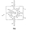
Figure 1 is a side view of a die having a pair of inserts disclosed therein. -
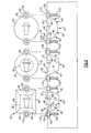
Figure 2 is a further disclosure of the die inserts ofFigure 1 including top and side views of differently shaped dies and die inserts. - Referring now to
Figure 1 an embodiment of a die 10 is shown. The embodiment includes a top die 15, a bottom die 20, a top dieinsert 25 and a bottom dieinsert 30. Both dies are driven by a press indicated byarrows 35 that supplies clamping forces that exert high pressure forces on thedie inserts part 40 to be die cast. - In the instant application, the
part 40 created by using the dies and die inserts is made of a high temperature nickel alloy that has a melting point around 2800°F - 2900°F (1540°C - 1595°C) though other high temperature and low temperature alloys may be used herein. The die inserts are typically made of a ceramic material like silicon nitride which can withstand temperatures up to 5000°F (2760°C). Silicon nitride has enviable properties like high strength over a wide temperature range, fracture toughness, high hardness, outstanding wear resistance, thermal shock resistance and chemical resistance. However other materials are known and are contemplated for use herein. - The upper and
lower die inserts lower dies sides 42 so that operation of the presses force the top die and the bottom die to provide the uniform compressive forces indicated byarrows 45 upon the upper andlower die inserts lower die inserts inserts - Referring now to
Figure 2 , several alternative embodiments of the die inserts 2A, 2B and 2C a side view oflower die 20 and lowerdie insert 30, and a bottom view of thetop die insert 25 are shown. - In
Figure 2A, theupper die insert 25 has arectangular top portion 50, arectangular bottom portion 55 and fourangled side surfaces 60 that attach thetop portion 50 to thebottom portion 55. Similarly, thelower die insert 30 mirrors theupper die insert 25. - In
Figure 2B , upper die insert has acircular top portion 65, acircular bottom portion 70 and aconical side surface 75 joining thetop portion 65 to thebottom portion 70 so that the die looks like a truncated cone. Similarly, thelower die insert 30 mirrors theupper die insert 25. - In
Figure 2C , upper die insert has a bowl-shaped top andside portion 80 and acircular face portion 85 so that the die looks like a bowl. Similarly, thelower die insert 30 mirrors theupper die insert 25. - Ideally the side surface forms an angle α that is greater than 90° between the
side surface 60 and the top surface 50 (seeFigure 2A ). - Each upper and lower die insert in
Figures 2A, 2B, and 2C have a pair ofshoulders 90 in amating surface 95 thereof and aside surface screw 100 will mate with the top surface and the side surface to hold the upper andlower die insert lower dies -
Screw 100 has alarge head 105 in which acounter sink 110 is disposed therein. In the embodiment shown, thecounter sink 110 is hexagonally-shaped to receive a hexagonally-shaped pin 115 that locates theupper die 15 atop thelower die 20. The screws mate withholes 120 within the upper andlower dies - Alternatively, the
pins 115 may be set or manufactured within thescrew 105 so that onescrew 105 disposed in thebottom die 20 would, for instance, mate with thescrew counter sink 110 in theupper die 15 or vice-versa. Other locating devices and other shaped countersinks are contemplated for use herein. - In operation, the upper die
insert 25 is inserted into a top die 15 and a bottom dieinsert 30 is placed in the bottom die 20. The inserts are secured to the dies byscrews 100 that fit intoholes 120 and the enlargedscrew head 100 holds theshoulders 90 of the upper andlower die inserts lower dies pins 115 that are inserted intocountersinks 110. Liquid metal is then injected at high temperature between the dies into the die cavity to create apart 40. - Although a combination of features is shown in the illustrated examples, not all of them need to be combined to realize the benefits of various embodiments of this disclosure. In other words, a system designed according to an embodiment of this disclosure will not necessarily include all of the features shown in any one of the Figures or all of the portions schematically shown in the Figures. Moreover, selected features of one example embodiment may be combined with selected features of other example embodiments.
- The preceding description is exemplary rather than limiting in nature. Variations and modifications to the disclosed examples may become apparent to those skilled in the art that do not necessarily depart from the essence of this disclosure. The scope of legal protection given to this disclosure can only be determined by studying the following claims.
Claims (12)
- An apparatus for casting material, said apparatus comprising:a die for receiving a compressive force and having a shaped opening for receiving a die insert, anda die insert having an exterior shape that is adapted to cooperate with and be received in said opening such that compressive forces impinging upon said die are focused upon said die insert and such that tensile forces within said die and impinging upon said die insert are minimized.
- The apparatus of claim 1 wherein said exterior shape of said die insert is angled from a surface away from a mating surface thereof towards a mating surface thereof.
- The apparatus of claim 2 wherein said angle is greater than 90°.
- The apparatus of any preceding claim wherein said die insert is constructed of a ceramic material.
- The apparatus of claim 4 wherein said ceramic material is silicon nitride.
- The apparatus of any preceding claim wherein said die is adapted for use with parts made of a high temperature nickel alloy.
- The apparatus of any preceding claim wherein said die inserts have a shoulder for holding said die insert within said die.
- The apparatus of claim 7 further comprising a fastener which impinges upon said shoulder and attaches to said die for holding said die insert within said die.
- The apparatus of claim 8 wherein said fastener is a screw having a head resting on said shoulder and a body anchored to said die.
- The apparatus of any preceding claim wherein said exterior shape of said die insert and shaped-opening of said die are analogous.
- The apparatus of claim 10 wherein said exterior shape of said die insert and shaped-opening of said die are identical.
- The apparatus of any preceding claim wherein parts made in said die insert are for use in jet engines.
Applications Claiming Priority (1)
| Application Number | Priority Date | Filing Date | Title |
|---|---|---|---|
| US12/730,498 US8814557B2 (en) | 2010-03-24 | 2010-03-24 | Die inserts for die casting |
Publications (3)
| Publication Number | Publication Date |
|---|---|
| EP2371469A2 true EP2371469A2 (en) | 2011-10-05 |
| EP2371469A3 EP2371469A3 (en) | 2016-03-02 |
| EP2371469B1 EP2371469B1 (en) | 2019-11-06 |
Family
ID=43929062
Family Applications (1)
| Application Number | Title | Priority Date | Filing Date |
|---|---|---|---|
| EP11250327.1A Active EP2371469B1 (en) | 2010-03-24 | 2011-03-16 | Configuration of die inserts for high temperature die-casting |
Country Status (2)
| Country | Link |
|---|---|
| US (1) | US8814557B2 (en) |
| EP (1) | EP2371469B1 (en) |
Cited By (1)
| Publication number | Priority date | Publication date | Assignee | Title |
|---|---|---|---|---|
| WO2020058401A1 (en) * | 2018-09-19 | 2020-03-26 | Fraunhofer-Gesellschaft zur Förderung der angewandten Forschung e.V. | Casting mold for casting components and method for the production thereof |
Families Citing this family (2)
| Publication number | Priority date | Publication date | Assignee | Title |
|---|---|---|---|---|
| USD830432S1 (en) | 2016-06-06 | 2018-10-09 | Ipex Technologies Inc. | 3D printed mold inserts |
| CN108500836B (en) * | 2018-06-04 | 2024-04-12 | 江苏汤普斯伦新材料科技有限公司 | Guide rail grinding machine foundation member adopting mineral castings and preparation method |
Family Cites Families (58)
| Publication number | Priority date | Publication date | Assignee | Title |
|---|---|---|---|---|
| US1370191A (en) * | 1919-02-05 | 1921-03-01 | Walter W Crate | Mold for making artificial teeth |
| US2339792A (en) * | 1941-09-10 | 1944-01-25 | Maryland Plastics Inc | Apparatus for producing molded plastic articles |
| US2323014A (en) * | 1941-09-30 | 1943-06-29 | Faultless Rubber Co | Molding means |
| US2633603A (en) * | 1950-06-28 | 1953-04-07 | Hiram N Huse | Mold |
| US3068522A (en) * | 1960-07-19 | 1962-12-18 | David L Nickerson | Method and apparatus for molding covers on spherical bodies |
| US3258818A (en) * | 1965-03-31 | 1966-07-05 | Symington Wayne Corp | Method of casting metals |
| US3380121A (en) * | 1965-07-30 | 1968-04-30 | American Can Co | Mold with replaceable inserts |
| US3409344A (en) * | 1967-03-03 | 1968-11-05 | Reflex Corp Canada Ltd | Roadway reflectors |
| US3680354A (en) | 1970-03-23 | 1972-08-01 | Allegheny Ludlum Steel | Die assembly |
| US3581804A (en) * | 1970-05-11 | 1971-06-01 | Hamilton Die Cast Inc | Expansion gap compensating system for a die |
| US3905744A (en) * | 1972-10-31 | 1975-09-16 | Kennametal Inc | Die member for briquetting apparatus |
| US3844755A (en) * | 1972-11-16 | 1974-10-29 | Eastman Kodak Co | Method and apparatus for transfer molding glass lenses |
| US4100962A (en) * | 1977-02-28 | 1978-07-18 | James H. Housman | Casting die |
| US4196769A (en) * | 1978-03-20 | 1980-04-08 | Remet Corporation | Ceramic shell mold |
| US4167388A (en) * | 1978-05-01 | 1979-09-11 | United Technologies Corporation | Apparatus for forming hollow members |
| US4309020A (en) * | 1980-07-31 | 1982-01-05 | Nalco Chemical Company | Patchless replacement refractory insert for base member (stool) with mechanical anchoring |
| DE3112751A1 (en) * | 1981-03-31 | 1982-10-07 | Fa. Carl Zeiss, 7920 Heidenheim | MOLDING TOOL FOR PRODUCING PARTS FROM THERMOPLASTIC MATERIAL |
| DE3128347A1 (en) * | 1981-07-17 | 1983-02-03 | Eugen Dipl.-Ing. 8871 Burtenbach Bühler | PROCESS AND EQUIPMENT FOR THE MANUFACTURE OF MOLDINGS FROM FREE-FLOW MASS KEYWORD: "MAINTAINING THE FILLING VACUUM DURING ISOSTATIC PRESSING" |
| JPS602343A (en) * | 1983-06-20 | 1985-01-08 | Nanba Press Kogyo Kk | Formation of reinforcing layer on inner surface of complicated hollow molding |
| US4704079A (en) * | 1984-04-02 | 1987-11-03 | Minnesota Mining And Manufacturing Company | Mold having ceramic insert |
| JPS61121915A (en) * | 1984-11-19 | 1986-06-09 | Matsushita Electric Ind Co Ltd | Mold device |
| JPS6256111A (en) * | 1985-09-05 | 1987-03-11 | Sony Corp | Resin sealing mold |
| US4701999A (en) | 1985-12-17 | 1987-10-27 | Pnc, Inc. | Method of making sealed housings containing delicate structures |
| JPH0677924B2 (en) * | 1987-07-20 | 1994-10-05 | 日本碍子株式会社 | Mold and method for molding ceramics using the same |
| US5075053A (en) | 1988-08-04 | 1991-12-24 | Gte Valenite Corporation | Method of making cutting insert |
| US5116450A (en) * | 1990-07-23 | 1992-05-26 | Phillips Petroleum Company | Molding apparatus |
| DE4212584A1 (en) * | 1992-04-15 | 1993-10-21 | Krupp Corpoplast Masch | Preload device |
| JPH08122770A (en) | 1994-10-19 | 1996-05-17 | Hosiden Corp | Liquid crystal display element |
| ES2156221T3 (en) * | 1994-12-19 | 2001-06-16 | Aga Ab | PROCEDURE INCLUDING HEATING AND COOLING FOR THE PRODUCTION OF A BODY MOLDED BY INJECTION. |
| JP2804451B2 (en) * | 1995-03-23 | 1998-09-24 | 日本碍子株式会社 | Compression molding dies for composite insulator production |
| US5741446A (en) * | 1995-05-26 | 1998-04-21 | Mitsubishi Engineering-Plastics Corp. | Method of producing a molded article using a mold assembly with an insert block |
| US5997273A (en) | 1995-08-01 | 1999-12-07 | Laquer; Henry Louis | Differential pressure HIP forging in a controlled gaseous environment |
| DE19636968B4 (en) * | 1996-09-12 | 2008-08-07 | Steinbeis Transferzentrum Arbeitsgemeinschaft Metallguss An Der Fachhochschule Aalen | Process for the production of metallic prototypes |
| US5968302A (en) * | 1997-05-16 | 1999-10-19 | Ova Nail Products, Inc. | Methods for manufacturing precision fit fingernails |
| US6165407A (en) * | 1997-05-28 | 2000-12-26 | Mitsubishi Engineering-Plastics Corp. | Mold assembly for molding thermoplastic resin and method of manufacturing molded article of thermoplastic resin |
| US6551086B1 (en) * | 1997-06-23 | 2003-04-22 | The Goodyear Tire & Rubber Co. | Tire mold reinforcement |
| AUPP060497A0 (en) | 1997-11-28 | 1998-01-08 | Commonwealth Scientific And Industrial Research Organisation | Magnesium pressure die casting |
| DE60036565D1 (en) * | 1999-12-16 | 2007-11-08 | Porvair Plc | DEVICE AND METHOD FOR SEALING CERAMIC PARTS |
| JP2002240098A (en) * | 2001-02-15 | 2002-08-28 | Sony Corp | Molding mold, method of manufacturing molding mold, and molded article molded by molding mold |
| JP3920040B2 (en) * | 2001-04-10 | 2007-05-30 | 株式会社小糸製作所 | Vehicular lamp, mold for injection molding of lamp body, and manufacturing method thereof |
| JP2003014938A (en) * | 2001-04-12 | 2003-01-15 | Mitsubishi Engineering Plastics Corp | Light guide plate made of transparent resin and molding method thereof, nesting, mold assembly, and planar light source device |
| JP2003010957A (en) * | 2001-06-28 | 2003-01-15 | Ube Machinery Corporation Ltd | Structure of gate made of ceramics |
| US20030015308A1 (en) * | 2001-07-23 | 2003-01-23 | Fosaaen Ken E. | Core and pattern manufacture for investment casting |
| JP3948272B2 (en) * | 2001-12-21 | 2007-07-25 | スズキ株式会社 | Engine bearing cap manufacturing method |
| KR20040077752A (en) * | 2002-01-22 | 2004-09-06 | 이 아이 듀폰 디 네모아 앤드 캄파니 | Compression mould for making a membrane electrode assembly |
| JP3893411B2 (en) * | 2003-04-28 | 2007-03-14 | 幸央 竹田 | Manufacturing method of polarizing lens |
| US6904666B2 (en) * | 2003-07-31 | 2005-06-14 | Andrew Corporation | Method of manufacturing microwave filter components and microwave filter components formed thereby |
| US20050236729A1 (en) * | 2004-04-23 | 2005-10-27 | Arnott Robin A | Method and apparatus for vibrating melt in an injection molding machine using active material elements |
| DE502004005078D1 (en) | 2004-04-30 | 2007-11-08 | Sgl Carbon Ag | Workpiece carrier for inductive heating of workpieces |
| US7270166B2 (en) * | 2004-06-28 | 2007-09-18 | Howmet Corporation | Fugitive pattern assembly and method |
| US7134475B2 (en) | 2004-10-29 | 2006-11-14 | United Technologies Corporation | Investment casting cores and methods |
| US20060261514A1 (en) * | 2005-05-17 | 2006-11-23 | Sri Sports Limited | Method for the production of golf ball |
| US7434432B1 (en) | 2005-08-18 | 2008-10-14 | Hi-Tech Welding And Forming, Inc. | Die apparatus and method for high temperature forming of metal products |
| FI20055453A0 (en) | 2005-08-29 | 2005-08-29 | Valtion Teknillinen | Injection molding of mesh metal components comprising functionally layered microstructures |
| US20070264474A1 (en) * | 2006-05-11 | 2007-11-15 | Visteon Global Technologies, Inc. | Component for a vehicle interior and a mold assembly and a method for assembling the component |
| JP4990356B2 (en) * | 2006-05-11 | 2012-08-01 | ビューラー・ドルックグス・アクチエンゲゼルシャフト | Molding method and apparatus for producing castings |
| US7520741B2 (en) * | 2006-07-21 | 2009-04-21 | Acushnet Company | Replaceable mold cavities |
| US20110094698A1 (en) * | 2009-10-28 | 2011-04-28 | Howmet Corporation | Fugitive core tooling and method |
-
2010
- 2010-03-24 US US12/730,498 patent/US8814557B2/en not_active Expired - Fee Related
-
2011
- 2011-03-16 EP EP11250327.1A patent/EP2371469B1/en active Active
Non-Patent Citations (1)
| Title |
|---|
| None |
Cited By (2)
| Publication number | Priority date | Publication date | Assignee | Title |
|---|---|---|---|---|
| WO2020058401A1 (en) * | 2018-09-19 | 2020-03-26 | Fraunhofer-Gesellschaft zur Förderung der angewandten Forschung e.V. | Casting mold for casting components and method for the production thereof |
| US11612930B2 (en) | 2018-09-19 | 2023-03-28 | Fraunhofer-Gesellschaft zur Förderung der angewandten Forschung e.V. | Casting mold for casting components and method for the production thereof |
Also Published As
| Publication number | Publication date |
|---|---|
| US8814557B2 (en) | 2014-08-26 |
| EP2371469B1 (en) | 2019-11-06 |
| US20110233378A1 (en) | 2011-09-29 |
| EP2371469A3 (en) | 2016-03-02 |
Similar Documents
| Publication | Publication Date | Title |
|---|---|---|
| US4614630A (en) | Mold having ceramic insert, method for injection molding using the same | |
| US8662143B1 (en) | Mold having ceramic insert | |
| US4704079A (en) | Mold having ceramic insert | |
| US8814557B2 (en) | Die inserts for die casting | |
| KR102465786B1 (en) | Sleeve for die casting and manufacturing method thereof | |
| CN105705271A (en) | Methods and apparatus to produce high performance axisymmetric components | |
| JP2005074461A (en) | Manufacturing method of molded products | |
| JPH09314301A (en) | Manufacturing method of light alloy wheel hubs | |
| CN105195673B (en) | A method of investment casting of bimetal composite cracking connecting rod | |
| US5964274A (en) | Die assembly for a die casting machine | |
| CN104190737A (en) | Amorphous metal extrusion die capable of rapidly replacing die core, and extrusion process thereof | |
| JP5923074B2 (en) | Die casting machine injection head structure | |
| US20040211544A1 (en) | Apparatus and method for casting metal | |
| KR100644914B1 (en) | Detachable ring toggle on multi slide die casting machines | |
| JP4150413B2 (en) | Method and apparatus for casting ingot of aluminum alloy for cutting made of the same material as aluminum alloy for mass production | |
| EP0178093A1 (en) | An improved metal core for use in plastics moulding | |
| US11590559B2 (en) | Method of manufacturing cast product and forged product with insert joined thereto | |
| JPH09239513A (en) | Die to be used for die casting of cast iron | |
| JP2014176853A (en) | Die-casting metal mold and casting method | |
| Advekar et al. | Simulation of high pressure die casting process for identifying and minimising defects | |
| CN111201097A (en) | Method for producing a cast workpiece | |
| CN218252695U (en) | High-precision die forging and shackle die | |
| CN102059334A (en) | Method for directly casting and molding magnesium base composite material through flow deformation | |
| JP2016097433A (en) | Casting metal mold | |
| JP7292715B2 (en) | SEMI-SOLID MATERIAL FORGING APPARATUS AND SEMI-SOLID MATERIAL FORGING METHOD |
Legal Events
| Date | Code | Title | Description |
|---|---|---|---|
| PUAI | Public reference made under article 153(3) epc to a published international application that has entered the european phase |
Free format text: ORIGINAL CODE: 0009012 |
|
| AK | Designated contracting states |
Kind code of ref document: A2 Designated state(s): AL AT BE BG CH CY CZ DE DK EE ES FI FR GB GR HR HU IE IS IT LI LT LU LV MC MK MT NL NO PL PT RO RS SE SI SK SM TR |
|
| AX | Request for extension of the european patent |
Extension state: BA ME |
|
| RIC1 | Information provided on ipc code assigned before grant |
Ipc: B22D 17/24 20060101AFI20150812BHEP Ipc: B22D 19/00 20060101ALI20150812BHEP |
|
| PUAL | Search report despatched |
Free format text: ORIGINAL CODE: 0009013 |
|
| AK | Designated contracting states |
Kind code of ref document: A3 Designated state(s): AL AT BE BG CH CY CZ DE DK EE ES FI FR GB GR HR HU IE IS IT LI LT LU LV MC MK MT NL NO PL PT RO RS SE SI SK SM TR |
|
| AX | Request for extension of the european patent |
Extension state: BA ME |
|
| RIC1 | Information provided on ipc code assigned before grant |
Ipc: B22D 17/24 20060101AFI20160122BHEP Ipc: B22D 19/00 20060101ALI20160122BHEP |
|
| 17P | Request for examination filed |
Effective date: 20160830 |
|
| RBV | Designated contracting states (corrected) |
Designated state(s): AL AT BE BG CH CY CZ DE DK EE ES FI FR GB GR HR HU IE IS IT LI LT LU LV MC MK MT NL NO PL PT RO RS SE SI SK SM TR |
|
| RIN1 | Information on inventor provided before grant (corrected) |
Inventor name: BULLIED, STEVEN J. Inventor name: BALES, DANIEL A Inventor name: VERNER, CARL R. |
|
| RAP1 | Party data changed (applicant data changed or rights of an application transferred) |
Owner name: UNITED TECHNOLOGIES CORPORATION |
|
| STAA | Information on the status of an ep patent application or granted ep patent |
Free format text: STATUS: EXAMINATION IS IN PROGRESS |
|
| 17Q | First examination report despatched |
Effective date: 20180307 |
|
| GRAP | Despatch of communication of intention to grant a patent |
Free format text: ORIGINAL CODE: EPIDOSNIGR1 |
|
| STAA | Information on the status of an ep patent application or granted ep patent |
Free format text: STATUS: GRANT OF PATENT IS INTENDED |
|
| INTG | Intention to grant announced |
Effective date: 20190517 |
|
| GRAS | Grant fee paid |
Free format text: ORIGINAL CODE: EPIDOSNIGR3 |
|
| GRAA | (expected) grant |
Free format text: ORIGINAL CODE: 0009210 |
|
| STAA | Information on the status of an ep patent application or granted ep patent |
Free format text: STATUS: THE PATENT HAS BEEN GRANTED |
|
| AK | Designated contracting states |
Kind code of ref document: B1 Designated state(s): AL AT BE BG CH CY CZ DE DK EE ES FI FR GB GR HR HU IE IS IT LI LT LU LV MC MK MT NL NO PL PT RO RS SE SI SK SM TR |
|
| REG | Reference to a national code |
Ref country code: GB Ref legal event code: FG4D |
|
| REG | Reference to a national code |
Ref country code: CH Ref legal event code: EP Ref country code: AT Ref legal event code: REF Ref document number: 1198076 Country of ref document: AT Kind code of ref document: T Effective date: 20191115 |
|
| REG | Reference to a national code |
Ref country code: DE Ref legal event code: R096 Ref document number: 602011063172 Country of ref document: DE |
|
| REG | Reference to a national code |
Ref country code: IE Ref legal event code: FG4D |
|
| REG | Reference to a national code |
Ref country code: NL Ref legal event code: MP Effective date: 20191106 |
|
| REG | Reference to a national code |
Ref country code: LT Ref legal event code: MG4D |
|
| PG25 | Lapsed in a contracting state [announced via postgrant information from national office to epo] |
Ref country code: NL Free format text: LAPSE BECAUSE OF FAILURE TO SUBMIT A TRANSLATION OF THE DESCRIPTION OR TO PAY THE FEE WITHIN THE PRESCRIBED TIME-LIMIT Effective date: 20191106 Ref country code: SE Free format text: LAPSE BECAUSE OF FAILURE TO SUBMIT A TRANSLATION OF THE DESCRIPTION OR TO PAY THE FEE WITHIN THE PRESCRIBED TIME-LIMIT Effective date: 20191106 Ref country code: LV Free format text: LAPSE BECAUSE OF FAILURE TO SUBMIT A TRANSLATION OF THE DESCRIPTION OR TO PAY THE FEE WITHIN THE PRESCRIBED TIME-LIMIT Effective date: 20191106 Ref country code: PL Free format text: LAPSE BECAUSE OF FAILURE TO SUBMIT A TRANSLATION OF THE DESCRIPTION OR TO PAY THE FEE WITHIN THE PRESCRIBED TIME-LIMIT Effective date: 20191106 Ref country code: NO Free format text: LAPSE BECAUSE OF FAILURE TO SUBMIT A TRANSLATION OF THE DESCRIPTION OR TO PAY THE FEE WITHIN THE PRESCRIBED TIME-LIMIT Effective date: 20200206 Ref country code: GR Free format text: LAPSE BECAUSE OF FAILURE TO SUBMIT A TRANSLATION OF THE DESCRIPTION OR TO PAY THE FEE WITHIN THE PRESCRIBED TIME-LIMIT Effective date: 20200207 Ref country code: LT Free format text: LAPSE BECAUSE OF FAILURE TO SUBMIT A TRANSLATION OF THE DESCRIPTION OR TO PAY THE FEE WITHIN THE PRESCRIBED TIME-LIMIT Effective date: 20191106 Ref country code: ES Free format text: LAPSE BECAUSE OF FAILURE TO SUBMIT A TRANSLATION OF THE DESCRIPTION OR TO PAY THE FEE WITHIN THE PRESCRIBED TIME-LIMIT Effective date: 20191106 Ref country code: PT Free format text: LAPSE BECAUSE OF FAILURE TO SUBMIT A TRANSLATION OF THE DESCRIPTION OR TO PAY THE FEE WITHIN THE PRESCRIBED TIME-LIMIT Effective date: 20200306 Ref country code: FI Free format text: LAPSE BECAUSE OF FAILURE TO SUBMIT A TRANSLATION OF THE DESCRIPTION OR TO PAY THE FEE WITHIN THE PRESCRIBED TIME-LIMIT Effective date: 20191106 Ref country code: BG Free format text: LAPSE BECAUSE OF FAILURE TO SUBMIT A TRANSLATION OF THE DESCRIPTION OR TO PAY THE FEE WITHIN THE PRESCRIBED TIME-LIMIT Effective date: 20200206 |
|
| PG25 | Lapsed in a contracting state [announced via postgrant information from national office to epo] |
Ref country code: HR Free format text: LAPSE BECAUSE OF FAILURE TO SUBMIT A TRANSLATION OF THE DESCRIPTION OR TO PAY THE FEE WITHIN THE PRESCRIBED TIME-LIMIT Effective date: 20191106 Ref country code: RS Free format text: LAPSE BECAUSE OF FAILURE TO SUBMIT A TRANSLATION OF THE DESCRIPTION OR TO PAY THE FEE WITHIN THE PRESCRIBED TIME-LIMIT Effective date: 20191106 Ref country code: IS Free format text: LAPSE BECAUSE OF FAILURE TO SUBMIT A TRANSLATION OF THE DESCRIPTION OR TO PAY THE FEE WITHIN THE PRESCRIBED TIME-LIMIT Effective date: 20200306 |
|
| PG25 | Lapsed in a contracting state [announced via postgrant information from national office to epo] |
Ref country code: AL Free format text: LAPSE BECAUSE OF FAILURE TO SUBMIT A TRANSLATION OF THE DESCRIPTION OR TO PAY THE FEE WITHIN THE PRESCRIBED TIME-LIMIT Effective date: 20191106 |
|
| PG25 | Lapsed in a contracting state [announced via postgrant information from national office to epo] |
Ref country code: CZ Free format text: LAPSE BECAUSE OF FAILURE TO SUBMIT A TRANSLATION OF THE DESCRIPTION OR TO PAY THE FEE WITHIN THE PRESCRIBED TIME-LIMIT Effective date: 20191106 Ref country code: EE Free format text: LAPSE BECAUSE OF FAILURE TO SUBMIT A TRANSLATION OF THE DESCRIPTION OR TO PAY THE FEE WITHIN THE PRESCRIBED TIME-LIMIT Effective date: 20191106 Ref country code: DK Free format text: LAPSE BECAUSE OF FAILURE TO SUBMIT A TRANSLATION OF THE DESCRIPTION OR TO PAY THE FEE WITHIN THE PRESCRIBED TIME-LIMIT Effective date: 20191106 Ref country code: RO Free format text: LAPSE BECAUSE OF FAILURE TO SUBMIT A TRANSLATION OF THE DESCRIPTION OR TO PAY THE FEE WITHIN THE PRESCRIBED TIME-LIMIT Effective date: 20191106 |
|
| REG | Reference to a national code |
Ref country code: DE Ref legal event code: R097 Ref document number: 602011063172 Country of ref document: DE |
|
| REG | Reference to a national code |
Ref country code: AT Ref legal event code: MK05 Ref document number: 1198076 Country of ref document: AT Kind code of ref document: T Effective date: 20191106 |
|
| PG25 | Lapsed in a contracting state [announced via postgrant information from national office to epo] |
Ref country code: SK Free format text: LAPSE BECAUSE OF FAILURE TO SUBMIT A TRANSLATION OF THE DESCRIPTION OR TO PAY THE FEE WITHIN THE PRESCRIBED TIME-LIMIT Effective date: 20191106 Ref country code: SM Free format text: LAPSE BECAUSE OF FAILURE TO SUBMIT A TRANSLATION OF THE DESCRIPTION OR TO PAY THE FEE WITHIN THE PRESCRIBED TIME-LIMIT Effective date: 20191106 |
|
| PLBE | No opposition filed within time limit |
Free format text: ORIGINAL CODE: 0009261 |
|
| STAA | Information on the status of an ep patent application or granted ep patent |
Free format text: STATUS: NO OPPOSITION FILED WITHIN TIME LIMIT |
|
| 26N | No opposition filed |
Effective date: 20200807 |
|
| PG25 | Lapsed in a contracting state [announced via postgrant information from national office to epo] |
Ref country code: MC Free format text: LAPSE BECAUSE OF FAILURE TO SUBMIT A TRANSLATION OF THE DESCRIPTION OR TO PAY THE FEE WITHIN THE PRESCRIBED TIME-LIMIT Effective date: 20191106 |
|
| REG | Reference to a national code |
Ref country code: CH Ref legal event code: PL |
|
| PG25 | Lapsed in a contracting state [announced via postgrant information from national office to epo] |
Ref country code: SI Free format text: LAPSE BECAUSE OF FAILURE TO SUBMIT A TRANSLATION OF THE DESCRIPTION OR TO PAY THE FEE WITHIN THE PRESCRIBED TIME-LIMIT Effective date: 20191106 Ref country code: AT Free format text: LAPSE BECAUSE OF FAILURE TO SUBMIT A TRANSLATION OF THE DESCRIPTION OR TO PAY THE FEE WITHIN THE PRESCRIBED TIME-LIMIT Effective date: 20191106 |
|
| REG | Reference to a national code |
Ref country code: BE Ref legal event code: MM Effective date: 20200331 |
|
| PG25 | Lapsed in a contracting state [announced via postgrant information from national office to epo] |
Ref country code: LU Free format text: LAPSE BECAUSE OF NON-PAYMENT OF DUE FEES Effective date: 20200316 |
|
| PG25 | Lapsed in a contracting state [announced via postgrant information from national office to epo] |
Ref country code: IT Free format text: LAPSE BECAUSE OF FAILURE TO SUBMIT A TRANSLATION OF THE DESCRIPTION OR TO PAY THE FEE WITHIN THE PRESCRIBED TIME-LIMIT Effective date: 20191106 Ref country code: IE Free format text: LAPSE BECAUSE OF NON-PAYMENT OF DUE FEES Effective date: 20200316 Ref country code: CH Free format text: LAPSE BECAUSE OF NON-PAYMENT OF DUE FEES Effective date: 20200331 Ref country code: LI Free format text: LAPSE BECAUSE OF NON-PAYMENT OF DUE FEES Effective date: 20200331 |
|
| PG25 | Lapsed in a contracting state [announced via postgrant information from national office to epo] |
Ref country code: BE Free format text: LAPSE BECAUSE OF NON-PAYMENT OF DUE FEES Effective date: 20200331 |
|
| PGFP | Annual fee paid to national office [announced via postgrant information from national office to epo] |
Ref country code: FR Payment date: 20210218 Year of fee payment: 11 |
|
| PGFP | Annual fee paid to national office [announced via postgrant information from national office to epo] |
Ref country code: DE Payment date: 20210217 Year of fee payment: 11 Ref country code: GB Payment date: 20210219 Year of fee payment: 11 |
|
| PG25 | Lapsed in a contracting state [announced via postgrant information from national office to epo] |
Ref country code: TR Free format text: LAPSE BECAUSE OF FAILURE TO SUBMIT A TRANSLATION OF THE DESCRIPTION OR TO PAY THE FEE WITHIN THE PRESCRIBED TIME-LIMIT Effective date: 20191106 Ref country code: MT Free format text: LAPSE BECAUSE OF FAILURE TO SUBMIT A TRANSLATION OF THE DESCRIPTION OR TO PAY THE FEE WITHIN THE PRESCRIBED TIME-LIMIT Effective date: 20191106 Ref country code: CY Free format text: LAPSE BECAUSE OF FAILURE TO SUBMIT A TRANSLATION OF THE DESCRIPTION OR TO PAY THE FEE WITHIN THE PRESCRIBED TIME-LIMIT Effective date: 20191106 |
|
| PG25 | Lapsed in a contracting state [announced via postgrant information from national office to epo] |
Ref country code: MK Free format text: LAPSE BECAUSE OF FAILURE TO SUBMIT A TRANSLATION OF THE DESCRIPTION OR TO PAY THE FEE WITHIN THE PRESCRIBED TIME-LIMIT Effective date: 20191106 |
|
| REG | Reference to a national code |
Ref country code: DE Ref legal event code: R081 Ref document number: 602011063172 Country of ref document: DE Owner name: RAYTHEON TECHNOLOGIES CORPORATION (N.D.GES.D.S, US Free format text: FORMER OWNER: UNITED TECHNOLOGIES CORPORATION, FARMINGTON, CONN., US |
|
| REG | Reference to a national code |
Ref country code: DE Ref legal event code: R119 Ref document number: 602011063172 Country of ref document: DE |
|
| GBPC | Gb: european patent ceased through non-payment of renewal fee |
Effective date: 20220316 |
|
| PG25 | Lapsed in a contracting state [announced via postgrant information from national office to epo] |
Ref country code: GB Free format text: LAPSE BECAUSE OF NON-PAYMENT OF DUE FEES Effective date: 20220316 Ref country code: FR Free format text: LAPSE BECAUSE OF NON-PAYMENT OF DUE FEES Effective date: 20220331 Ref country code: DE Free format text: LAPSE BECAUSE OF NON-PAYMENT OF DUE FEES Effective date: 20221001 |