EP2371438A1 - Liquid/gas separator device - Google Patents
Liquid/gas separator device Download PDFInfo
- Publication number
- EP2371438A1 EP2371438A1 EP11159928A EP11159928A EP2371438A1 EP 2371438 A1 EP2371438 A1 EP 2371438A1 EP 11159928 A EP11159928 A EP 11159928A EP 11159928 A EP11159928 A EP 11159928A EP 2371438 A1 EP2371438 A1 EP 2371438A1
- Authority
- EP
- European Patent Office
- Prior art keywords
- liquid
- level
- container
- previous
- tank
- Prior art date
- Legal status (The legal status is an assumption and is not a legal conclusion. Google has not performed a legal analysis and makes no representation as to the accuracy of the status listed.)
- Granted
Links
Images

Classifications
-
- B—PERFORMING OPERATIONS; TRANSPORTING
- B01—PHYSICAL OR CHEMICAL PROCESSES OR APPARATUS IN GENERAL
- B01D—SEPARATION
- B01D19/00—Degasification of liquids
- B01D19/0063—Regulation, control including valves and floats
Definitions
- the present invention relates to a liquid/gas separator device, in particular for water/hydrogen.
- the water is disposed of and the hydrogen re-emitted as fuel or a carrier gas for chemical analysis.
- a mixture of H 2 O and H 2 reaches a tank 10 through a duct 20, pushed by the pressure of a PEM cell upstream of the same (not shown).
- a float 12 is present in the tank 10 which is free to float and which is fitted with two rubber portions 14, one on the top side and one on the bottom side.
- the bottom of the tank 10 is not flat but raised in the centre by a cone 16, which is hollow and open at the tip.
- a similar cone 18 is positioned on the top of the tank 10 and acts as a vent.
- the main object of the present invention is to improve this state of the art. This object is achieved by a device which functions reliably over time.
- a device according to the invention is indicated by reference numeral 50. It comprises a tank 52 which a mixture of H 2 and H 2 O reaches through a duct 54, pushed by the pressure of a PEM cell upstream of the same (not shown). A ball float 56 is present in the tank 52 and free to float on the water which accumulates. The spherical shape of the float is advantageous because it eliminates any risk of it getting stuck.
- the bottom of the tank 52 communicates by means of a water outflow duct 58 with a solenoid valve 60, used to block the flow of water towards a collection tank (not shown).
- a solenoid valve 60 used to block the flow of water towards a collection tank (not shown).
- proportional valves or equivalent valve devices may also be used.
- the top of the tank 52 communicates rather by means of a hydrogen outflow duct 62 towards hydrogen collection means (not shown).
- the tank 52 On the outside of the lateral walls of the tank 52 are two infrared transmitters 70, 72 (e.g. IR LEDs), and two infrared sensors or receivers 74, 76 (e.g. IR photodiodes), arranged in pairs on a horizontal axis so that a sensor receives the infrared beam from the respective transmitter.
- the two sensors 70, 72 are connected to a microprocessor or processing unit 78, which receives the signal.
- the microprocessor 78 is in turn connected to the valve 60 to drive its opening or closing.
- the tank 52 is preferably made of transparent material, such as Plexiglas®. This way the electronics and especially the IR emitters 70, 72 may be situated externally to the tank 52, near its outer lateral surface, and the IR rays intercept the float 56 better.
- the transmitters 70, 72 and the two receivers 74, 76 are mounted on relative printed circuits 90 (U-shaped) which are placed closely around the tank 52 ( fig. 3 ).
- relative printed circuits 90 U-shaped
- other types of sensors may be used for the water level e.g. capacity sensors, a video camera etc.
- the functioning of the device 50 is as follows:
- both H 2 O and H 2 reach the tank 52 from the duct 54.
- the water descends and accumulates on the bottom of the tank 52, while the hydrogen rises upwards. As the water accumulates it raises the float 56 until it comes to position itself between and be detected by, the first IR emitter and receiver 70, 74, pair which in relation to the bottom is situated lower down than the other pair 72, 76.
- the microprocessor 78 acts by means of a suitable logic or program and operates the valve 60 switching its state from open to closed or vice versa.
- the microprocessor 78 acts by means of a suitable logic or program and operates the valve 60 switching its state from open to closed or vice versa.
- the valve 60 is pulse-operated, preferably at intervals of 500msec for a time varying from 5 ms to 30 ms. This way the water comes out in small quantities without generating particular pressure drops.
- the infrared means 70, 74 (and 72, 76), the microprocessor 78 and the valve 60 constitute a feedback loop, wherein for example the algorithm performed digitally by the microprocessor 78 is of the PID type.
- the pulsed operation of the valve 60 therefore makes the water level remain constant at the (approximate) height of the infrared devices 70, 74 (or rather of their beam).
- the system interprets this condition as indicating that water drainage is not functioning correctly and therefore signals the event to activate the appropriate safety measures.
- This is dealt with by a specific part of code in the microprocessor 78, which can force the maximum aperture of the valve 60 and/or activate acoustic or visual signals, and/or send a specific signal to a remote PC and/or handle the visualisation of an alarm message on a display (not shown).
- the float 56 not reaching a sufficient height to obstruct the beam of the first sensor may be considered a system anomaly. Again, this may be dealt with by a specific part of code of the microprocessor 78, which may be connected to internally simulate timer means. When an established maximum time has elapsed, the microprocessor 78 may activate and/or handle signalling of an alarm (e.g. using the devices and methods indicated for the previous condition).
- the system can also function without the float, e.g. by measuring the water level with other means or sensors not requiring one. During trial tests it was observed however that drops may form on the walls of the tank 52 as a result of phenomena related to pressure, temperature and water impurities, disturbing direct measurement. To make measurement safer it is therefore preferable to insert the float (e.g. a small plastic sphere) or opaque floating element and make it interrupt for example a beam of electromagnetic radiation.
- the float e.g. a small plastic sphere
- opaque floating element e.g. a small plastic sphere
- the position of the outtake from the tank 52 for the water, upstream of the duct 58, may also be at a certain height from the bottom of the tank 52, so as to make a small sub-tank or volume (in its lower part) in the tank 52 for the deposit of any impurities.
- a solenoid valve makes the separator 50 immune from the presence of any foreign bodies in the H 2 O + H 2 mixture, at least of small dimensions.
- the solenoid valve 60 is by nature an extremely reliable component, so that maintenance is reduced to a minimum. It should be emphasised that in the separator 50 the user can constantly check if the system is functioning or not, making the system more reliable.
- the microprocessor 78 may be interfaced with visualisation (display, monitor, etc.) and/or alarm and/or signalling means.
- Another advantage is the possibility of working in the presence of vibrations.
- FIGS 5 and 6 show a variant 100 for the separator device of the invention.
- a filter 104 e.g. in steel or titanium fibre
- the filter 104 takes the form of a foil or disc, placed over the mouth of the water outflow duct.
Landscapes
- Chemical & Material Sciences (AREA)
- Chemical Kinetics & Catalysis (AREA)
- Physical Water Treatments (AREA)
- Separating Particles In Gases By Inertia (AREA)
- Degasification And Air Bubble Elimination (AREA)
- Sampling And Sample Adjustment (AREA)
Abstract
- measurement means (70, 74) for measuring, or reaching of, a level of liquid in the container;
- valve means (60) positioned on an outflow for the liquid from the container;
- control means (78) cooperating with the measuring means so as to receive the measurement of the level of liquid and adapted to act consequentially on the valve means to maintain a predefined level of liquid in the container.
Description
- The present invention relates to a liquid/gas separator device, in particular for water/hydrogen.
- Nowadays devices are known which separate oxygen from a gas, in particular from hydrogen (H2). Given a mixture of water (H2O) and gas these must be separated as thoroughly as possible. This need arises above all for H2 generators using PEM (Proton Exchange Membrane) cells. At the outlet of the PEM cell, by its very nature, H2 and H2O are obtained, from which the need to separate them.
- Normally the water is disposed of and the hydrogen re-emitted as fuel or a carrier gas for chemical analysis.
- Said equipment functions mechanically-see
Fig.1 using an extremely primitive functioning principle. A mixture of H2O and H2 reaches atank 10 through aduct 20, pushed by the pressure of a PEM cell upstream of the same (not shown). Afloat 12 is present in thetank 10 which is free to float and which is fitted with tworubber portions 14, one on the top side and one on the bottom side. The bottom of thetank 10 is not flat but raised in the centre by acone 16, which is hollow and open at the tip. Asimilar cone 18 is positioned on the top of thetank 10 and acts as a vent. - The water reaching the
tank 10 falls to the bottom and accumulates while the hydrogen, which is volatile, escapes from thecone 18. When the water reaches a sufficient level to raise thefloat 12, it begins to flow out through thecone 16, otherwise thelower rubber portion 14 closes thecone 16 and there is no outflow. Theupper rubber portion 14 rather, is used to prevent the water from coming out of thecone 18 should thecone 16 become obstructed. - There are many problems with this system, that is to say:
- the sizing of the float is difficult, since this depends on the working pressure of the hydrogen and of the mixture reaching the
tank 10; - complicated mechanical machining is required to make the
float 12 and thecones rubber portions 14 abut with the cones. Here machining must be extremely precise because otherwise thefloat 12 could get stuck; - there is no direct way of knowing if the device malfunctions, in particular if there are leaks of water or hydrogen;
- it is sufficient for a minute foreign body (even of a hundredth of a mm) to deposit on the outlet orifice of the
cone - it is not possible to insert a filter before the outlet hole;
- deterioration of the
rubber parts 14 causes immediate malfunctioning of the system, thereby making their regular replacement necessary. This is because an important feature of the device is that no hydrogen escapes together with the water; - in the presence of vibrations the systems develops leaks of hydrogen.
- The main object of the present invention is to improve this state of the art. This object is achieved by a device which functions reliably over time.
- This and other objects are achieved by a separator device as defined in claim 1, while preferred embodiments of the invention are contained in the dependent claims.
- The following description of a preferred embodiment will highlight the advantages of the invention, also illustrated in the appended drawing wherein:
-
fig.1 shows a schematic view of a known separator; -
fig.2 shows a schematic view of a separator according to the invention; -
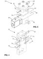
fig.3 shows a three-dimensional view of the separator infig.2 ; -
fig.4 shows a three-dimensional view in cross-section offig.2 ; - fig. 5 shows a three-dimensional view in cross-section of a variation of the separator;
- fig.6 shows a lateral view in cross-section of the variant in fig.5;
- A device according to the invention is indicated by
reference numeral 50. It comprises atank 52 which a mixture of H2 and H2O reaches through aduct 54, pushed by the pressure of a PEM cell upstream of the same (not shown). Aball float 56 is present in thetank 52 and free to float on the water which accumulates. The spherical shape of the float is advantageous because it eliminates any risk of it getting stuck. - The bottom of the
tank 52 communicates by means of awater outflow duct 58 with asolenoid valve 60, used to block the flow of water towards a collection tank (not shown). In place of thesolenoid valve 60 proportional valves or equivalent valve devices may also be used. The top of thetank 52 communicates rather by means of ahydrogen outflow duct 62 towards hydrogen collection means (not shown). - On the outside of the lateral walls of the
tank 52 are twoinfrared transmitters 70, 72 (e.g. IR LEDs), and two infrared sensors orreceivers 74, 76 (e.g. IR photodiodes), arranged in pairs on a horizontal axis so that a sensor receives the infrared beam from the respective transmitter. The twosensors processing unit 78, which receives the signal. Themicroprocessor 78 is in turn connected to thevalve 60 to drive its opening or closing. Thetank 52 is preferably made of transparent material, such as Plexiglas®. This way the electronics and especially theIR emitters tank 52, near its outer lateral surface, and the IR rays intercept thefloat 56 better. - Advantageously, the
transmitters receivers fig. 3 ). Note that other types of sensors may be used for the water level e.g. capacity sensors, a video camera etc. The functioning of thedevice 50 is as follows: - Thanks to the pressure of the mixture of H2O and H2 (above atmospheric pressure) and/or to gravity, both H2O and H2 reach the
tank 52 from theduct 54. - The water descends and accumulates on the bottom of the
tank 52, while the hydrogen rises upwards. As the water accumulates it raises thefloat 56 until it comes to position itself between and be detected by, the first IR emitter andreceiver other pair - The
microprocessor 78 acts by means of a suitable logic or program and operates thevalve 60 switching its state from open to closed or vice versa. By exploiting the internal pressure in thetank 52, with thevalve 60 open the water comes out spontaneously along theduct 58. A small part of the liquid always remains to prevent the hydrogen from coming out of the bottom through theduct 58. - The
valve 60 is pulse-operated, preferably at intervals of 500msec for a time varying from 5 ms to 30 ms. This way the water comes out in small quantities without generating particular pressure drops. For greater precision, it is preferred that the infrared means 70, 74 (and 72, 76), themicroprocessor 78 and thevalve 60 constitute a feedback loop, wherein for example the algorithm performed digitally by themicroprocessor 78 is of the PID type. - The pulsed operation of the
valve 60 therefore makes the water level remain constant at the (approximate) height of theinfrared devices 70, 74 (or rather of their beam). - If the water level increases so much as to bring the
float 56 to interrupt the IR beam of the secondinfrared emitter 72, the system interprets this condition as indicating that water drainage is not functioning correctly and therefore signals the event to activate the appropriate safety measures. This is dealt with by a specific part of code in themicroprocessor 78, which can force the maximum aperture of thevalve 60 and/or activate acoustic or visual signals, and/or send a specific signal to a remote PC and/or handle the visualisation of an alarm message on a display (not shown). - As a further safety measure, the
float 56 not reaching a sufficient height to obstruct the beam of the first sensor may be considered a system anomaly. Again, this may be dealt with by a specific part of code of themicroprocessor 78, which may be connected to internally simulate timer means. When an established maximum time has elapsed, themicroprocessor 78 may activate and/or handle signalling of an alarm (e.g. using the devices and methods indicated for the previous condition). - It should be noted that the system can also function without the float, e.g. by measuring the water level with other means or sensors not requiring one. During trial tests it was observed however that drops may form on the walls of the
tank 52 as a result of phenomena related to pressure, temperature and water impurities, disturbing direct measurement. To make measurement safer it is therefore preferable to insert the float (e.g. a small plastic sphere) or opaque floating element and make it interrupt for example a beam of electromagnetic radiation. - The position of the outtake from the
tank 52 for the water, upstream of theduct 58, may also be at a certain height from the bottom of thetank 52, so as to make a small sub-tank or volume (in its lower part) in thetank 52 for the deposit of any impurities. - From what has been said, it is easy to see that the advantages of the
separator 50 are many. As well as its compact dimensions, it is produced with low mechanical machining costs. Reliability is decidedly superior, for example since there are no drainage holes smaller than 0.3 mm which could become obstructed. There is then a system for detecting functioning failure, entirely lacking in the prior art. Electronic control lastly guarantees the necessary programming versatility of the functions and intervention precision. - It should be noted that the use of a solenoid valve makes the
separator 50 immune from the presence of any foreign bodies in the H2O + H2 mixture, at least of small dimensions. Thesolenoid valve 60 is by nature an extremely reliable component, so that maintenance is reduced to a minimum. It should be emphasised that in theseparator 50 the user can constantly check if the system is functioning or not, making the system more reliable. To such purpose themicroprocessor 78 may be interfaced with visualisation (display, monitor, etc.) and/or alarm and/or signalling means. - Another advantage is the possibility of working in the presence of vibrations.
- The models of the prior art, in the presence of vibrations, shows leakage of H2, which does not occur with the invention.
- Figures 5 and 6 show a variant 100 for the separator device of the invention. As can be seen there is a filter 104 (e.g. in steel or titanium fibre) placed on the bottom of the tank 112 upstream of the exit duct 102 of H2O. The filter 104 takes the form of a foil or disc, placed over the mouth of the water outflow duct.
- By means of the filter 104 a foreign body is prevented from blocking the outflow duct or hole 102 for the water and the solenoid valve 160 downstream of it. It should be noted that the conditions for use of a proportional rather than ON/OFF-valve thus become more favourable. In the system of the prior art described initially a filter cannot be placed in this position. The only option would be to place it before the entrance of the separator but, should it become obstructed, this would generate a safety problem — of overpressure- of the upstream circuit.
Claims (11)
- Liquid/gas separator device (50) comprising a container (52) to contain the mixture of liquid and gas, characterised by the fact of comprising- measurement means (70, 74) for measuring, or reaching of, a level of liquid in the container;- valve means (60) positioned on an outflow for the liquid from the container;- control means (78) cooperating with the measuring means so as to receive the measurement of the level of liquid and adapted to act consequentially on the valve means to maintain a predefined level of liquid in the container.
- Device according to claim 1, wherein the measurement means comprise emitter (70, 72) and receiver (74,76) means of electromagnetic radiations adapted for generating a beam of electromagnetic radiation which can be interrupted at a predefined level, and wherein the control means comprise a microprocessor.
- Device according to claim 2, wherein the measurement means comprise a floating element (56) adapted for floating on a quantity of liquid which accumulates on the bottom of the container and for interrupting a beam of electromagnetic radiations at the predefined level.
- Device according to any of the previous claims, wherein the tank (52) is made of transparent material.
- Device according to any of the previous claims, comprising second measurement means (74, 76) for measuring a second level of liquid in the container above said predefined level of liquid, and wherein the control means co-operate with the second measurement means to signal an anomaly and/or stop the device and/or force the state of the valve means if the level of liquid reaches said second level.
- Device according to any of the previous claims from 2 to 5, wherein the emitter and receiver means of electromagnetic radiations are mounted on a printed circuit (80) placed around or in such a manner as to embrace the tank (52).
- Device according to any of the previous claims, comprising timer means associated with the control means, the latter being adapted to signal an anomaly and/or stop the device and/or force the state of the valve means if, within a predefined time measured by the timer means, the measurement means do not indicate reaching of a minimum level of liquid.
- Device according to any of the previous claims, comprising an outtake of liquid on the container (52) situated at a certain height from the bottom of the container (52), so as to make a small sub-tank or volume in the tank (52) for the deposit of any impurities.
- Device according to any of the previous claims, wherein the control means are configured to operate on the valve means (60) periodically switching their status from open to closed or vice versa.
- Device according to any of the previous claims, wherein the measurement means, control means and valve means are connected so as to form a feedback system the reference of which is a predefined level of the liquid.
- Device according to any of the previous claims, comprising a filter (104) placed between the valve means and the outflow for the liquid from the tank suitable to withhold any corpuscles present in the liquid.
Applications Claiming Priority (1)
| Application Number | Priority Date | Filing Date | Title |
|---|---|---|---|
| IT000048A ITTV20100048A1 (en) | 2010-03-31 | 2010-03-31 | LIQUID / GAS SEPARATOR DEVICE |
Publications (2)
| Publication Number | Publication Date |
|---|---|
| EP2371438A1 true EP2371438A1 (en) | 2011-10-05 |
| EP2371438B1 EP2371438B1 (en) | 2020-03-11 |
Family
ID=43243789
Family Applications (1)
| Application Number | Title | Priority Date | Filing Date |
|---|---|---|---|
| EP11159928.8A Active EP2371438B1 (en) | 2010-03-31 | 2011-03-28 | Liquid/gas separator device |
Country Status (2)
| Country | Link |
|---|---|
| EP (1) | EP2371438B1 (en) |
| IT (1) | ITTV20100048A1 (en) |
Cited By (2)
| Publication number | Priority date | Publication date | Assignee | Title |
|---|---|---|---|---|
| EP2878866A1 (en) | 2013-11-15 | 2015-06-03 | Microprogel Srl | Safety valve for gas-carrying ducts |
| IT202000007702A1 (en) | 2020-04-10 | 2021-10-10 | Microprogel S R L | "Method and apparatus for de-ionizing the feed water of a PEM cell" |
Citations (4)
| Publication number | Priority date | Publication date | Assignee | Title |
|---|---|---|---|---|
| AU6323373A (en) * | 1973-12-05 | 1975-06-05 | Diessel Gmbh & Co | Device for measuring quantities of liquid |
| US5743135A (en) * | 1993-08-27 | 1998-04-28 | Vlsi Technology, Inc. | Optical-fiber liquid-level monitor |
| CA2595031A1 (en) * | 2006-08-10 | 2008-02-10 | Giraffe Liquid Management Systems, Inc. | Apparatus and method for content discrimination |
| WO2010034325A1 (en) * | 2008-09-24 | 2010-04-01 | Statoilhydro Asa | Gas-liquid separator |
Family Cites Families (2)
| Publication number | Priority date | Publication date | Assignee | Title |
|---|---|---|---|---|
| US5389264A (en) * | 1993-07-12 | 1995-02-14 | Zimpro Environmental Inc. | Hydraulic energy dissipator for wet oxidation process |
| NO320427B1 (en) * | 2002-12-23 | 2005-12-05 | Norsk Hydro As | A system and method for predicting and handling fluid or gas plugs in a pipeline system |
-
2010
- 2010-03-31 IT IT000048A patent/ITTV20100048A1/en unknown
-
2011
- 2011-03-28 EP EP11159928.8A patent/EP2371438B1/en active Active
Patent Citations (4)
| Publication number | Priority date | Publication date | Assignee | Title |
|---|---|---|---|---|
| AU6323373A (en) * | 1973-12-05 | 1975-06-05 | Diessel Gmbh & Co | Device for measuring quantities of liquid |
| US5743135A (en) * | 1993-08-27 | 1998-04-28 | Vlsi Technology, Inc. | Optical-fiber liquid-level monitor |
| CA2595031A1 (en) * | 2006-08-10 | 2008-02-10 | Giraffe Liquid Management Systems, Inc. | Apparatus and method for content discrimination |
| WO2010034325A1 (en) * | 2008-09-24 | 2010-04-01 | Statoilhydro Asa | Gas-liquid separator |
Cited By (3)
| Publication number | Priority date | Publication date | Assignee | Title |
|---|---|---|---|---|
| EP2878866A1 (en) | 2013-11-15 | 2015-06-03 | Microprogel Srl | Safety valve for gas-carrying ducts |
| IT202000007702A1 (en) | 2020-04-10 | 2021-10-10 | Microprogel S R L | "Method and apparatus for de-ionizing the feed water of a PEM cell" |
| EP3892758A1 (en) | 2020-04-10 | 2021-10-13 | MicroPROGEL SRL | Method and apparatus for de-ionizing the supply water of a pem cell |
Also Published As
| Publication number | Publication date |
|---|---|
| EP2371438B1 (en) | 2020-03-11 |
| ITTV20100048A1 (en) | 2011-10-01 |
Similar Documents
| Publication | Publication Date | Title |
|---|---|---|
| EP0569728A1 (en) | Liquid supply apparatus | |
| EP2340867B1 (en) | Humidification chamber with a safety sensor for detecting excessive levels of liquid | |
| SK18302002A3 (en) | Infusion of liquids into the human or animal body | |
| EP2371438B1 (en) | Liquid/gas separator device | |
| KR20180086411A (en) | Solenoid assembly for valves | |
| CN211324418U (en) | Full-automatic liquid injection system of liquid drinking machine and liquid drinking machine | |
| US9322487B2 (en) | Nuclear grade air accumulation, indication and venting device | |
| US8800365B2 (en) | Method for registering the filling potential of a waste container of microplate washing devices | |
| US4610848A (en) | Device for the dosable addition of a substance to a solvent | |
| RU2241924C2 (en) | Cooling device | |
| JPH07177832A (en) | Drinking water feeder for experimental small animal | |
| AU2018204116B2 (en) | Harsh environment differential pressure monitor | |
| KR102052614B1 (en) | Apparatus for discharging air and measuring discharged air | |
| KR102060092B1 (en) | Floating sensor and wet tank for scrubber having the same | |
| US5325725A (en) | Water cooled stator winding leak detector | |
| KR101845066B1 (en) | Rainfall measuring device verification | |
| US10473545B2 (en) | Equipment for controlling, measuring and communicating a physical quantity of a container containing a fluid under pressure | |
| US4065675A (en) | Flow monitoring devices | |
| WO2024173286A1 (en) | Gas production and storage system and associated methods | |
| US20110120577A1 (en) | Nuclear Grade Air Accumulation, Indication and Venting Device | |
| CN210378890U (en) | Water level detection switch | |
| US4964307A (en) | Liquid flow measuring device | |
| CA2597769A1 (en) | Liquid blocking apparatus and system equipped with an alarm or wireless calling device and a storing bag | |
| KR101977026B1 (en) | Apparatus for automatic fluid extracting and method for the same | |
| CN221528109U (en) | Anti-overflow's closed circuit sampler |
Legal Events
| Date | Code | Title | Description |
|---|---|---|---|
| PUAI | Public reference made under article 153(3) epc to a published international application that has entered the european phase |
Free format text: ORIGINAL CODE: 0009012 |
|
| AK | Designated contracting states |
Kind code of ref document: A1 Designated state(s): AL AT BE BG CH CY CZ DE DK EE ES FI FR GB GR HR HU IE IS IT LI LT LU LV MC MK MT NL NO PL PT RO RS SE SI SK SM TR |
|
| AX | Request for extension of the european patent |
Extension state: BA ME |
|
| 17P | Request for examination filed |
Effective date: 20120328 |
|
| 17Q | First examination report despatched |
Effective date: 20160720 |
|
| STAA | Information on the status of an ep patent application or granted ep patent |
Free format text: STATUS: EXAMINATION IS IN PROGRESS |
|
| GRAP | Despatch of communication of intention to grant a patent |
Free format text: ORIGINAL CODE: EPIDOSNIGR1 |
|
| STAA | Information on the status of an ep patent application or granted ep patent |
Free format text: STATUS: GRANT OF PATENT IS INTENDED |
|
| INTG | Intention to grant announced |
Effective date: 20191001 |
|
| GRAS | Grant fee paid |
Free format text: ORIGINAL CODE: EPIDOSNIGR3 |
|
| GRAA | (expected) grant |
Free format text: ORIGINAL CODE: 0009210 |
|
| STAA | Information on the status of an ep patent application or granted ep patent |
Free format text: STATUS: THE PATENT HAS BEEN GRANTED |
|
| RIN1 | Information on inventor provided before grant (corrected) |
Inventor name: GAFFO, VALTER |
|
| AK | Designated contracting states |
Kind code of ref document: B1 Designated state(s): AL AT BE BG CH CY CZ DE DK EE ES FI FR GB GR HR HU IE IS IT LI LT LU LV MC MK MT NL NO PL PT RO RS SE SI SK SM TR |
|
| REG | Reference to a national code |
Ref country code: GB Ref legal event code: FG4D |
|
| REG | Reference to a national code |
Ref country code: CH Ref legal event code: EP |
|
| REG | Reference to a national code |
Ref country code: AT Ref legal event code: REF Ref document number: 1242428 Country of ref document: AT Kind code of ref document: T Effective date: 20200315 |
|
| REG | Reference to a national code |
Ref country code: IE Ref legal event code: FG4D |
|
| REG | Reference to a national code |
Ref country code: DE Ref legal event code: R096 Ref document number: 602011065471 Country of ref document: DE |
|
| PG25 | Lapsed in a contracting state [announced via postgrant information from national office to epo] |
Ref country code: NO Free format text: LAPSE BECAUSE OF FAILURE TO SUBMIT A TRANSLATION OF THE DESCRIPTION OR TO PAY THE FEE WITHIN THE PRESCRIBED TIME-LIMIT Effective date: 20200611 Ref country code: FI Free format text: LAPSE BECAUSE OF FAILURE TO SUBMIT A TRANSLATION OF THE DESCRIPTION OR TO PAY THE FEE WITHIN THE PRESCRIBED TIME-LIMIT Effective date: 20200311 Ref country code: RS Free format text: LAPSE BECAUSE OF FAILURE TO SUBMIT A TRANSLATION OF THE DESCRIPTION OR TO PAY THE FEE WITHIN THE PRESCRIBED TIME-LIMIT Effective date: 20200311 |
|
| REG | Reference to a national code |
Ref country code: NL Ref legal event code: MP Effective date: 20200311 |
|
| PG25 | Lapsed in a contracting state [announced via postgrant information from national office to epo] |
Ref country code: GR Free format text: LAPSE BECAUSE OF FAILURE TO SUBMIT A TRANSLATION OF THE DESCRIPTION OR TO PAY THE FEE WITHIN THE PRESCRIBED TIME-LIMIT Effective date: 20200612 Ref country code: BG Free format text: LAPSE BECAUSE OF FAILURE TO SUBMIT A TRANSLATION OF THE DESCRIPTION OR TO PAY THE FEE WITHIN THE PRESCRIBED TIME-LIMIT Effective date: 20200611 Ref country code: HR Free format text: LAPSE BECAUSE OF FAILURE TO SUBMIT A TRANSLATION OF THE DESCRIPTION OR TO PAY THE FEE WITHIN THE PRESCRIBED TIME-LIMIT Effective date: 20200311 Ref country code: LV Free format text: LAPSE BECAUSE OF FAILURE TO SUBMIT A TRANSLATION OF THE DESCRIPTION OR TO PAY THE FEE WITHIN THE PRESCRIBED TIME-LIMIT Effective date: 20200311 Ref country code: SE Free format text: LAPSE BECAUSE OF FAILURE TO SUBMIT A TRANSLATION OF THE DESCRIPTION OR TO PAY THE FEE WITHIN THE PRESCRIBED TIME-LIMIT Effective date: 20200311 |
|
| REG | Reference to a national code |
Ref country code: LT Ref legal event code: MG4D |
|
| PG25 | Lapsed in a contracting state [announced via postgrant information from national office to epo] |
Ref country code: NL Free format text: LAPSE BECAUSE OF FAILURE TO SUBMIT A TRANSLATION OF THE DESCRIPTION OR TO PAY THE FEE WITHIN THE PRESCRIBED TIME-LIMIT Effective date: 20200311 |
|
| PG25 | Lapsed in a contracting state [announced via postgrant information from national office to epo] |
Ref country code: PT Free format text: LAPSE BECAUSE OF FAILURE TO SUBMIT A TRANSLATION OF THE DESCRIPTION OR TO PAY THE FEE WITHIN THE PRESCRIBED TIME-LIMIT Effective date: 20200805 Ref country code: LT Free format text: LAPSE BECAUSE OF FAILURE TO SUBMIT A TRANSLATION OF THE DESCRIPTION OR TO PAY THE FEE WITHIN THE PRESCRIBED TIME-LIMIT Effective date: 20200311 Ref country code: SM Free format text: LAPSE BECAUSE OF FAILURE TO SUBMIT A TRANSLATION OF THE DESCRIPTION OR TO PAY THE FEE WITHIN THE PRESCRIBED TIME-LIMIT Effective date: 20200311 Ref country code: EE Free format text: LAPSE BECAUSE OF FAILURE TO SUBMIT A TRANSLATION OF THE DESCRIPTION OR TO PAY THE FEE WITHIN THE PRESCRIBED TIME-LIMIT Effective date: 20200311 Ref country code: CZ Free format text: LAPSE BECAUSE OF FAILURE TO SUBMIT A TRANSLATION OF THE DESCRIPTION OR TO PAY THE FEE WITHIN THE PRESCRIBED TIME-LIMIT Effective date: 20200311 Ref country code: IS Free format text: LAPSE BECAUSE OF FAILURE TO SUBMIT A TRANSLATION OF THE DESCRIPTION OR TO PAY THE FEE WITHIN THE PRESCRIBED TIME-LIMIT Effective date: 20200711 Ref country code: RO Free format text: LAPSE BECAUSE OF FAILURE TO SUBMIT A TRANSLATION OF THE DESCRIPTION OR TO PAY THE FEE WITHIN THE PRESCRIBED TIME-LIMIT Effective date: 20200311 Ref country code: SK Free format text: LAPSE BECAUSE OF FAILURE TO SUBMIT A TRANSLATION OF THE DESCRIPTION OR TO PAY THE FEE WITHIN THE PRESCRIBED TIME-LIMIT Effective date: 20200311 |
|
| REG | Reference to a national code |
Ref country code: CH Ref legal event code: PL |
|
| REG | Reference to a national code |
Ref country code: AT Ref legal event code: MK05 Ref document number: 1242428 Country of ref document: AT Kind code of ref document: T Effective date: 20200311 |
|
| REG | Reference to a national code |
Ref country code: DE Ref legal event code: R097 Ref document number: 602011065471 Country of ref document: DE |
|
| REG | Reference to a national code |
Ref country code: BE Ref legal event code: MM Effective date: 20200331 |
|
| PG25 | Lapsed in a contracting state [announced via postgrant information from national office to epo] |
Ref country code: LU Free format text: LAPSE BECAUSE OF NON-PAYMENT OF DUE FEES Effective date: 20200328 Ref country code: MC Free format text: LAPSE BECAUSE OF FAILURE TO SUBMIT A TRANSLATION OF THE DESCRIPTION OR TO PAY THE FEE WITHIN THE PRESCRIBED TIME-LIMIT Effective date: 20200311 |
|
| PLBE | No opposition filed within time limit |
Free format text: ORIGINAL CODE: 0009261 |
|
| STAA | Information on the status of an ep patent application or granted ep patent |
Free format text: STATUS: NO OPPOSITION FILED WITHIN TIME LIMIT |
|
| PG25 | Lapsed in a contracting state [announced via postgrant information from national office to epo] |
Ref country code: CH Free format text: LAPSE BECAUSE OF NON-PAYMENT OF DUE FEES Effective date: 20200331 Ref country code: IE Free format text: LAPSE BECAUSE OF NON-PAYMENT OF DUE FEES Effective date: 20200328 Ref country code: LI Free format text: LAPSE BECAUSE OF NON-PAYMENT OF DUE FEES Effective date: 20200331 Ref country code: ES Free format text: LAPSE BECAUSE OF FAILURE TO SUBMIT A TRANSLATION OF THE DESCRIPTION OR TO PAY THE FEE WITHIN THE PRESCRIBED TIME-LIMIT Effective date: 20200311 Ref country code: DK Free format text: LAPSE BECAUSE OF FAILURE TO SUBMIT A TRANSLATION OF THE DESCRIPTION OR TO PAY THE FEE WITHIN THE PRESCRIBED TIME-LIMIT Effective date: 20200311 Ref country code: AT Free format text: LAPSE BECAUSE OF FAILURE TO SUBMIT A TRANSLATION OF THE DESCRIPTION OR TO PAY THE FEE WITHIN THE PRESCRIBED TIME-LIMIT Effective date: 20200311 |
|
| 26N | No opposition filed |
Effective date: 20201214 |
|
| PG25 | Lapsed in a contracting state [announced via postgrant information from national office to epo] |
Ref country code: SI Free format text: LAPSE BECAUSE OF FAILURE TO SUBMIT A TRANSLATION OF THE DESCRIPTION OR TO PAY THE FEE WITHIN THE PRESCRIBED TIME-LIMIT Effective date: 20200311 Ref country code: PL Free format text: LAPSE BECAUSE OF FAILURE TO SUBMIT A TRANSLATION OF THE DESCRIPTION OR TO PAY THE FEE WITHIN THE PRESCRIBED TIME-LIMIT Effective date: 20200311 Ref country code: BE Free format text: LAPSE BECAUSE OF NON-PAYMENT OF DUE FEES Effective date: 20200331 |
|
| PG25 | Lapsed in a contracting state [announced via postgrant information from national office to epo] |
Ref country code: TR Free format text: LAPSE BECAUSE OF FAILURE TO SUBMIT A TRANSLATION OF THE DESCRIPTION OR TO PAY THE FEE WITHIN THE PRESCRIBED TIME-LIMIT Effective date: 20200311 Ref country code: MT Free format text: LAPSE BECAUSE OF FAILURE TO SUBMIT A TRANSLATION OF THE DESCRIPTION OR TO PAY THE FEE WITHIN THE PRESCRIBED TIME-LIMIT Effective date: 20200311 Ref country code: CY Free format text: LAPSE BECAUSE OF FAILURE TO SUBMIT A TRANSLATION OF THE DESCRIPTION OR TO PAY THE FEE WITHIN THE PRESCRIBED TIME-LIMIT Effective date: 20200311 |
|
| PG25 | Lapsed in a contracting state [announced via postgrant information from national office to epo] |
Ref country code: MK Free format text: LAPSE BECAUSE OF FAILURE TO SUBMIT A TRANSLATION OF THE DESCRIPTION OR TO PAY THE FEE WITHIN THE PRESCRIBED TIME-LIMIT Effective date: 20200311 Ref country code: AL Free format text: LAPSE BECAUSE OF FAILURE TO SUBMIT A TRANSLATION OF THE DESCRIPTION OR TO PAY THE FEE WITHIN THE PRESCRIBED TIME-LIMIT Effective date: 20200311 |
|
| P01 | Opt-out of the competence of the unified patent court (upc) registered |
Effective date: 20230515 |
|
| PGFP | Annual fee paid to national office [announced via postgrant information from national office to epo] |
Ref country code: GB Payment date: 20260327 Year of fee payment: 16 |
|
| PGFP | Annual fee paid to national office [announced via postgrant information from national office to epo] |
Ref country code: DE Payment date: 20260327 Year of fee payment: 16 |
|
| PGFP | Annual fee paid to national office [announced via postgrant information from national office to epo] |
Ref country code: IT Payment date: 20260311 Year of fee payment: 16 |
|
| PGFP | Annual fee paid to national office [announced via postgrant information from national office to epo] |
Ref country code: FR Payment date: 20260325 Year of fee payment: 16 |