EP2371269A1 - Perimeter and method of controlling perimeter - Google Patents
Perimeter and method of controlling perimeter Download PDFInfo
- Publication number
- EP2371269A1 EP2371269A1 EP11152283A EP11152283A EP2371269A1 EP 2371269 A1 EP2371269 A1 EP 2371269A1 EP 11152283 A EP11152283 A EP 11152283A EP 11152283 A EP11152283 A EP 11152283A EP 2371269 A1 EP2371269 A1 EP 2371269A1
- Authority
- EP
- European Patent Office
- Prior art keywords
- stimulus
- value
- luminance
- presented
- examinee
- Prior art date
- Legal status (The legal status is an assumption and is not a legal conclusion. Google has not performed a legal analysis and makes no representation as to the accuracy of the status listed.)
- Granted
Links
Images




Classifications
-
- A—HUMAN NECESSITIES
- A61—MEDICAL OR VETERINARY SCIENCE; HYGIENE
- A61B—DIAGNOSIS; SURGERY; IDENTIFICATION
- A61B3/00—Apparatus for testing the eyes; Instruments for examining the eyes
- A61B3/02—Subjective types, i.e. testing apparatus requiring the active assistance of the patient
- A61B3/024—Subjective types, i.e. testing apparatus requiring the active assistance of the patient for determining the visual field, e.g. perimeter types
Definitions
- This invention relates to a perimeter for measuring a visual field of an examinee in such a state that the examinee fixates a fixation target and a method of controlling the perimeter.
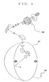
- Fig.5 is a typical view showing a structure of a perimeter.
- a reference numeral 300 denotes a projection optical system for projecting stimuli A
- a reference numeral 301 denotes a visual field dome in the shape of a semi-sphere for projecting stimuli A thereon.
- a reference numeral 303 denotes a response switch to be operated by an examinee.
- the projection optical system 300 When starting the perimeter in such a state that an examinee fixates a fixation target (a center point of the visual field dome 301, for example) inside the visual field dome 301, the projection optical system 300 successively displays stimuli A at various positions of the visual field dome 301. If the examinee do not perceive the stimulus A, luminance of the stimuli is gradually raised in order to obtain the luminance at which the examinee can perceive the stimulus.
- the method is comprised of (1) to conduct the above-mentioned perimetry on the examinee and to obtain the luminance of the stimulus which the examinee can perceive for two or more positions (stimulus presentation position), (2) to obtain a difference (total deviation) between a normal value (that is, a representative value of the luminance of the stimulus to be perceived with a normal eye, which is mentioned in detail later) and test results (that is, the luminance of the stimulus which the examinee actually perceived) for each position where the stimulus should be presented, (3) to obtain an average value (MD value: Mean Deviation value) obtained by dividing the total deviation obtained for each position where the stimulus should be presented by the number of positions where the stimulus should be presented, and (4) to show the changes with time of the MD value in a graph.
- MD value Mean Deviation value
- Fig. 6 is a view (graph) showing the changes of the MD value with time, and a longitudinal axis shows the MD value and a transverse axis shows time (that is, a date when each test is conducted). If sensitivity (that is, the luminance of the stimulus that can be perceived) of some examinee in some position (the position where the stimulus should be presented) in some test is lowered by 2dB in comparison with one in the last test for example, the total deviation in the position is also changed by 2dB and the MD value is changed thereby. Then, the progress of the disease is grasped by the change of the MD value.
- sensitivity that is, the luminance of the stimulus that can be perceived
- the other method is to obtain a PSD value (standard deviation of the above-mentioned total deviation) and to know changes thereof with time in order to grasp the progress of the disease.
- the sensitivity varies widely, depending on persons even if the persons have normal eyes. That is, the sensitivity of a normal eye of a person in some position may be different from the sensitivity of a normal eye of the other person in the position due to an individual difference. Even if the sensitivity of many persons having normal eyes in a predetermined position is measured, measurement result may not be the same but different. For example, the measurement result shows a distribution (characteristic curve) as shown in Fig.7 (a) . In a graph in Fig.7(a) , a transverse axis shows the sensitivity and a longitudinal axis shows number of persons.
- the sensitivity showing a peak in such a characteristic curve is defined as "a normal value”
- the sensitivity of a boundary between 95 percent of measured persons and 5 percent of the measured persons such as the sensitivity wherein 95 percent of the measured persons enter a right side range (that is, good sensitivity side) and the remaining 5 percent of the measured persons enter a left side range (that is, poor sensitivity side)
- p value 5%
- sensitivity dispersion range such characteristic curve changes depending on measurement positions.
- the above-mentioned MD value and the PSD value only show the same changes with time in both cases where the sensitivity is lowered by 2dB in the central portion and the peripheral portion of the visual field. For this reason, there is such a problem that it is not possible to make judgments as to whether the changes with time are considered to be important or not. Normal life is hindered if the sensitivity in the central portion of the visual field is lowered. Then, it is necessary to take some proper medical step if the sensitivity in the central portion of the visual field is lowered. But, it is difficult to make such judgments only with the changes with time.
- An object of the invention is to provide a perimeter for solving the above-mentioned problems and a method of controlling the perimeter.
- a first aspect of the invention is a perimeter as shown in Fig.1 , for example, for testing a visual field of an examinee in such a state the examinee fixates a predetermined fixation target, comprising:
- a second aspect of the invention is the perimeter, wherein said representative value is a value determined from a characteristic curve that shows a relation between "the luminance of the stimulus” obtained by conducting perimetry on a plurality of persons having normal eyes and "number of persons who actually perceived the stimulus having the luminance", and is the value based upon the luminance of the stimulus perceived by the most persons, a value based upon an average value obtained by dividing the perceived luminance by a number of said persons, or a value based upon the luminance of the stimulus perceived by almost middle rank of person when said persons are ranked based upon the perceived luminance.
- the third aspect of the perimeter further comprising:
- a fourth aspect of the invention is a method of controlling a perimeter, comprising:
- a fifth aspect of the invention is the method of controlling the perimeter, further comprising:
- a sensitivity dispersion region is different, depending on the positions where sensitivity is measured (that is, the position where the stimulus should be presented), and has an inclination to be the smallest in a center position of the visual field and to become bigger as the peripheral portion of the visual field draws close.
- the above-mentioned critical value is the value in connection with "change of the sensitivity dispersion region", and "the ratio to critical value” and “the total value or the average value of the ratio to critical value” is the value adding an element, "change of the sensitivity dispersion region" thereto.
- a perimeter according to the invention is constructed so as to test a visual field of an examinee in such a state that the examinee fixates a predetermined fixation target, such as a center point of a visual field dome 20B shown in Fig.2 ).
- a predetermined fixation target such as a center point of a visual field dome 20B shown in Fig.2 .
- Such a perimeter is exemplarily shown with a reference number 1 in Fig.1 or Fig.2 , and has stimulus presentation means 2 (will be mentioned in detail) for presenting a stimulus A having predetermined luminance at a plurality of peripheral positions of the fixation target ("the position where the stimulus should be presented" in the specification) in order.
- Such an perimeter 1 is provided with response means 3, such as a push switch. If the examinee who perceived the presented stimulus A (or an examiner watching a response of the examinee) operates the response means 3, response signals (that is, signals showing that the examinee actually perceived the presented stimulus) can be inputted into the perimeter 1 (concretely speaking, into luminance judging means 4).
- response means 3 such as a push switch. If the examinee who perceived the presented stimulus A (or an examiner watching a response of the examinee) operates the response means 3, response signals (that is, signals showing that the examinee actually perceived the presented stimulus) can be inputted into the perimeter 1 (concretely speaking, into luminance judging means 4).
- the perimeter 1 has luminance judging means 4 for judging luminance of the stimulus which the examinee perceived for each position where stimulus should be presented based upon signals from the stimulus presentation means 2 and the response means 3.
- Such luminance judging means 4 may output a difference between "luminance that is some standard (standard luminance)” and "measurement luminance (that is, the luminance of the stimulus which the examinee actually perceived)".
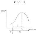
- Fig.3 There is an individual difference between persons having normal eyes in the luminance of the stimulus that can be perceived. Such an individual difference appears as a characteristic curve as shown in Fig.3 if perimetry is conducted on many (a plurality of) persons having normal eyes and data are collected.
- a transverse axis of Fig.3 shows sensitivity (that is, a value in connection with the luminance of the presented stimulus, and concretely speaking, a difference between the standard luminance and the measurement luminance) and a longitudinal axis shows a number of persons who have perceived the stimulus.
- any one of (1) a value based upon the luminance of the stimulus which the most persons have perceived (see a reference mark S 0 ), (2) a value based upon an average value obtained by dividing the perceived luminance by number of persons, (3) a value based upon the luminance of the stimulus which an almost middle rank of person have perceived if the persons who have perceived the stimulus are ranked based upon the perceived luminance (for example, the sensitivity of the 50 th person from the person having the best sensitivity, if perimetry is conducted on a hundred ofpersons), and (4) a value that is the other standard excluding the above-mentioned values, such as the sensitivity of the n-th person from the upper ranked person, is defined as "a normal value (corresponds to "a representative value" in claims)".
- the normal value (the representative value) of the luminance of the stimulus to be perceived by normal eyes is statistically obtained in the above-mentioned way in the invention. Since the above-mentioned characteristic curve is obtained by presenting the stimulus to the same position (the same position where the stimulus should be presented) betweenmanypersons, the other characteristic curve is obtained in the other position where the stimulus should be presented. So, the normal value (the representative value) is also different, depending on the position where the stimulus should be presented.
- the perimeter 1 according to the invention has normal value storing means 5 (represetative value storing means) for storing the normal value for each position where the stimulus should be presented as data.
- a critical value a critical value S 1 as shown in Fig.3 shows such a sensitivity that 95 percent of the persons are within a right side range (good sensitivity side) and 5 percent of the persons are within a left side region (poor sensitivity side).
- p value 5% , if necessary.
- the perimeter 1 has p value storing means 6 (critical value storing means) for storing p values for respective positions where the stimulus should be presented as data.
- the perimeter according to the invention has sensitivity deviation computing means 7 for computing a sensitivity deviation for each position where the stimulus should be presented from signals from the luminance judging means 4 and data of the normal value storing means 5 (that is, the normal value for each position where the stimulus should be presented).
- a sensitivity deviation is a concept including a total deviation and a pattern deviation, and means a difference between a value regarding the luminance of the stimulus which the examinee actually perceived (the luminance itself or the above-mentioned sensitivity) and the above-mentioned normal value (the luminance itself or the above-mentioned sensitivity).
- the perimeter 1 has means for computing ratio to p value 8 (means for computing ratio to critical value), which computes "ratio to p value (corresponds ratio to critical value in claims)" that is a ratio between the p value and the sensitivity deviation for each position where the stimulus should be presented.
- Such means for computing ratio to p value 8 may obtain a ratio of "p value ratio/sensitivity deviation or may obtain its inverse number (that is, the ratio of "sensitivity deviation/p value ratio”).
- the computed ratio to p value is 0.5 (or its inverse number 2).
- the ratio computed through means for computing ratio to p value 8 may not be such a ratio (the ratio in a strict meaning), but may be "some function between the sensitivity deviation and the p value” that changes due to the change of the sensitivity deviation.
- the perimeter 1 has means for adding ratios to p value (means for adding ratios to critical value) 9, which computes a total value of ratios to p value computed for respective positions where the stimulus should be presented or an average value obtained by dividing the total value by the number of the positions where the stimulus should be presented.
- the means for adding ratios to p value 9 includes means for obtaining the total value and the average value and also includes means for obtaining some value equivalent thereto.
- the concept of "the total value of the ratios to p value or the average value obtained by dividing the total value by the number of the positions where the stimulus should be presented" also includes some value obtained by using the ratio to p value of each position where the stimulus should be presented that is influenced by the change of any of the ratio to p value as well as the total value of the ratios to p value "B 1 + B 2 + B 3 +" and the average value of the ratios to p value "(B 1 + B 2 + B 3 +%) /n".
- a sensitivity dispersion region is different, depending on the positions where sensitivity is measured (that is, the position where the stimulus should be presented), and has an inclination to be the smallest in a center position of the visual field and to become bigger as the peripheral region of the visual field draws close.
- the above-mentioned p value (the critical value) is the value in connection with "change of the sensitivity dispersion region", and "the ratio to p value” and “the total value or the average value of the ratio to p value” is the value adding an element, "change of the sensitivity dispersion region" thereto.
- the numeral value (absolute value) becomes bigger if it is lowered at the central portion of the visual field and the total value or the average value of the ratio to p value is widely changed. Then, it is possible to judge as to whether it is important or not by watching changes of the total value or the average value of the ratio to p value with time even if the same amount of sensitivity deviation is lowered.
- test result storing means 10 that stores the total value or the average value computed by the means for adding ratios to p value 9 as well as examinee ID for identification of the examinee, and change output means 11 for outputting changes with time of the total value or the average value of the examinee, and to show a graph or a table on a printer 12 or a monitor 13 (see Fig.4 ).
- a method of controlling the perimeter 1 has a step of presenting the stimulus A having predetermined luminance in order to a plurality of positions where the stimulus should be presented through the stimulus presentation means 2; a step of judging the luminance of the stimulus perceived by the examinee for each position where the stimulus should be presented through the luminance judging means 4 based upon response signals showing that the examinee has perceived the presented stimulus (that is, the response signals from the response means 3) and signals from the stimulus presentation means 2; a step of computing the sensitivity deviation which is a difference between the value regarding the luminance of the stimulus perceived by the examinee and the normal value through the sensitivity deviation computing means 7 for each position where the stimulus should be presented based upon "the normal value of the luminance of the stimulus to be perceived with normal eyes” that is stored in the normal value storing means 5 as data in connection with each position where each stimulus should be presented and the signals from the luminance judging means 4; and a step of computing "the ratio to p value” that is the ratio between "the p value that is the
- the above-mentioned method may have a step of storing the total value or the average value that is computed by means of adding ratios to p value 9 through the test result storing means 10 as well as the examinee ID for identification of each examinee, and a step of outputting the change of the total value or the average value of the examinee with time through change output means 11.
- a structure of the stimulus presentation means 2 as shown in Fig.2 is mentioned briefly.
- a reference number 20 in the figure denotes the stimulus presentation portion for presenting stimulus A in the visual field of the examinee
- a reference numeral 21 denotes the presentation portion changing portion for changing the portion where the stimulus A is presented
- a reference numeral 22 denotes the luminance setting portion for setting the luminance of the stimulus A.
- the stimulus presentation portion 20 in the figure is comprised of a projection optical system 20A for projecting stimuli and projection member 20B where stimuli are projected by the projection optical system 20A, but may have any structure as long as the stimulus presentation portion 20 can present the stimuli in the visual field of the examinee. For example, a plurality of LEDs may be located and be selectively lighted.
- the projection member 20B in Fig.2 has a semi-spherical dome shape (visual field dome), but may have a shape with a curved face excluding a semi-sphere or a shape with a plane.
- the presentation portion changing portion 21 may be comprised of driving means for changing positions of structural elements of the projection optical system 20A, such as projector mirrors 211, 212 (not shown). If the stimulus presentation portion is comprised of a plurality of LEDs, which LED should be lighted may be controlled by the presentation portion changing portion. Even if any of the projection optical system and LED is used, an examiner may manually instruct to change the portion to be presented with a touch pen, a mouse or a keyboard, watching a display, or the change of the portion to be presented may be automatically instructed through a program prepared in advance.
- the luminance setting portion 22 as shown in Fig.2 is comprised of turrets 221, 222 having a plurality of filters rotatably supported which attenuation is different and driving mechanism 223 for changing positions of the turrets 221, 222, but may have another structure.
Landscapes
- Life Sciences & Earth Sciences (AREA)
- Health & Medical Sciences (AREA)
- Medical Informatics (AREA)
- Biophysics (AREA)
- Ophthalmology & Optometry (AREA)
- Engineering & Computer Science (AREA)
- Biomedical Technology (AREA)
- Heart & Thoracic Surgery (AREA)
- Physics & Mathematics (AREA)
- Molecular Biology (AREA)
- Surgery (AREA)
- Animal Behavior & Ethology (AREA)
- General Health & Medical Sciences (AREA)
- Public Health (AREA)
- Veterinary Medicine (AREA)
- Eye Examination Apparatus (AREA)
Abstract
Description
- The present disclosure relates to subject matter contained in Japanese patent application No.
2010-74729 filed on March 29, 2010 - This invention relates to a perimeter for measuring a visual field of an examinee in such a state that the examinee fixates a fixation target and a method of controlling the perimeter.
- When suffering from an ophthalmic disease, such as glaucoma and diabetic retinopathy, it is known that a person has a visual field contraction or a visual field defect. For these reasons, perimeters having various structures have been proposed as devices for finding such diseases (see Japanese patent application the publication number of which is
2002-272685 -
Fig.5 is a typical view showing a structure of a perimeter. InFig.5 , areference numeral 300 denotes a projection optical system for projecting stimuli A, and areference numeral 301 denotes a visual field dome in the shape of a semi-sphere for projecting stimuli A thereon. And, areference numeral 303 denotes a response switch to be operated by an examinee. - When starting the perimeter in such a state that an examinee fixates a fixation target (a center point of the
visual field dome 301, for example) inside thevisual field dome 301, the projectionoptical system 300 successively displays stimuli A at various positions of thevisual field dome 301. If the examinee do not perceive the stimulus A, luminance of the stimuli is gradually raised in order to obtain the luminance at which the examinee can perceive the stimulus. - In order to know a progress of an ophthalmic disease, such as glaucoma, it is necessary to periodically conduct the above-mentioned perimetry and to grasp changes with time of test results. Then, the following method has been adopted. That is, the method is comprised of (1) to conduct the above-mentioned perimetry on the examinee and to obtain the luminance of the stimulus which the examinee can perceive for two or more positions (stimulus presentation position), (2) to obtain a difference (total deviation) between a normal value (that is, a representative value of the luminance of the stimulus to be perceived with a normal eye, which is mentioned in detail later) and test results (that is, the luminance of the stimulus which the examinee actually perceived) for each position where the stimulus should be presented, (3) to obtain an average value (MD value: Mean Deviation value) obtained by dividing the total deviation obtained for each position where the stimulus should be presented by the number of positions where the stimulus should be presented, and (4) to show the changes with time of the MD value in a graph.
-
Fig. 6 is a view (graph) showing the changes of the MD value with time, and a longitudinal axis shows the MD value and a transverse axis shows time (that is, a date when each test is conducted). If sensitivity (that is, the luminance of the stimulus that can be perceived) of some examinee in some position (the position where the stimulus should be presented) in some test is lowered by 2dB in comparison with one in the last test for example, the total deviation in the position is also changed by 2dB and the MD value is changed thereby. Then, the progress of the disease is grasped by the change of the MD value. - The other method is to obtain a PSD value (standard deviation of the above-mentioned total deviation) and to know changes thereof with time in order to grasp the progress of the disease.
- The sensitivity varies widely, depending on persons even if the persons have normal eyes. That is, the sensitivity of a normal eye of a person in some position may be different from the sensitivity of a normal eye of the other person in the position due to an individual difference. Even if the sensitivity of many persons having normal eyes in a predetermined position is measured, measurement result may not be the same but different. For example, the measurement result shows a distribution (characteristic curve) as shown in
Fig.7 (a) . In a graph inFig.7(a) , a transverse axis shows the sensitivity and a longitudinal axis shows number of persons. If the sensitivity showing a peak in such a characteristic curve (the sensitivity shown with So inFig.7 (a) ) is defined as "a normal value", and the sensitivity of a boundary between 95 percent of measured persons and 5 percent of the measured persons, such as the sensitivity wherein 95 percent of the measured persons enter a right side range (that is, good sensitivity side) and the remaining 5 percent of the measured persons enter a left side range (that is, poor sensitivity side), is defined as "p value = 5%, and a range R between the normal value So and p value = 5% (see S1) is defined as "sensitivity dispersion range", such characteristic curve changes depending on measurement positions. Then, the normal value So, p value = 5% (see S1) and the sensitivity dispersion range R also change depending on the measurement positions (positions in the visual field). Such changes have an inclination as shown inFig. 7 (b) , and the sensitivity dispersion range is the smallest in the central portion of the visual field (see Ra), and becomes bigger as a peripheral portion of the visual field draws close (see Rb). For this reason, if the sensitivity is lowered by 2dB, there is a big problem in case where the position is in the central portion of the visual field (the central portion of the visual field where the sensitivity dispersion range is small), but it is not possible to make judgments only with the test results in a case where the position is in the peripheral portion of the visual field (the peripheral portion of the visual field where the sensitivity dispersion range is large). - However, the above-mentioned MD value and the PSD value only show the same changes with time in both cases where the sensitivity is lowered by 2dB in the central portion and the peripheral portion of the visual field. For this reason, there is such a problem that it is not possible to make judgments as to whether the changes with time are considered to be important or not. Normal life is hindered if the sensitivity in the central portion of the visual field is lowered. Then, it is necessary to take some proper medical step if the sensitivity in the central portion of the visual field is lowered. But, it is difficult to make such judgments only with the changes with time.
- An object of the invention is to provide a perimeter for solving the above-mentioned problems and a method of controlling the perimeter.
- A first aspect of the invention is a perimeter as shown in
Fig.1 , for example, for testing a visual field of an examinee in such a state the examinee fixates a predetermined fixation target, comprising: - stimulus presentation means for presenting a stimulus having predetermined luminance in order at a plurality of positions where stimulus should be presented in a periphery of said fixation target;
- response means through which an examiner or the examinee inputs response signals showing that the examinee actually perceived the presented stimulus;
- luminance judging means for judging said luminance of said stimulus perceived by the examinee for each position where said stimulus should be presented based upon signals from said stimulus presentation means and said response means;
- representative value storing means for storing "a representative value of the luminance of the stimulus to be perceived with normal eyes" statistically obtained in perimetry that is conducted on a plurality of persons having normal eyes as data in connection with each position where the stimulus should be presented;
- critical value storing means for storing "a critical value that shows a boundary of the luminance of the stimulus perceived by a predetermined rate of normal eyes" statistically obtained in perimetry that is conducted on a plurality of persons having normal eyes as data in connection with each position where the stimulus should be presented;
- sensitivity deviation computing means for computing sensitivity deviation that is a difference between a value in connection with the luminance of the stimulus perceived by the examinee and said representative value for each position where the stimulus should be presented based upon said signals from said luminance judging means and said data of said representative value storing means;
- means for computing ratio to critical value which computes "a ratio to critical value" that is a ratio between a critical value stored in said critical value storing means and said sensitivity deviation computed by said sensitivity deviation computing means for each position where the stimulus should be presented; and
- means for adding ratios to critical value, which computes a total value of said ratios to critical value computed for each position where the stimulus should be presented or an average value obtained by dividing said total value by number of positions where the stimulus should be presented.
- A second aspect of the invention is the perimeter, wherein said representative value is a value determined from a characteristic curve that shows a relation between "the luminance of the stimulus" obtained by conducting perimetry on a plurality of persons having normal eyes and "number of persons who actually perceived the stimulus having the luminance", and is the value based upon the luminance of the stimulus perceived by the most persons, a value based upon an average value obtained by dividing the perceived luminance by a number of said persons, or a value based upon the luminance of the stimulus perceived by almost middle rank of person when said persons are ranked based upon the perceived luminance.
- The third aspect of the perimeter, further comprising:
- test result storing means for storing said total value or said average value computed by said means for adding ratios to critical value as well as examinee ID for identification of the examinees; and
- change output means for outputting changes with time in the total value or the average value of the examinee.
- A fourth aspect of the invention is a method of controlling a perimeter, comprising:
- a step of presenting a stimulus having predetermined luminance in order to a plurality of positions where the stimulus should be presented through stimulus presentation means;
- a step of judging the luminance of the stimulus perceived by the examinee for each position where the stimulus should be presented through luminance judging means based upon response signals showing that the examinee has perceived the presented stimulus and signals from the stimulus presentation means;
- a step of computing sensitivity deviation which is a difference between a value regarding the luminance of the stimulus perceived by the examinee and the representative value through sensitivity deviation computing means for each position where the stimulus should be presented based upon "a representative value of the luminance of the stimulus to be perceived with normal eyes" that is stored in representative value storing means as data in connection with each position where each stimulus should be presented and the signals from the luminance judging means;
- a step of computing "a ratio to critical value" that is the ratio between "a critical value that is a boundary of the luminance of the stimulus perceived by a predetermined rate of normal eyes" that is stored in critical value storing means as data in connection with each position where the stimulus should be presented and the sensitivity deviation computed by the sensitivity deviation computing means for each position where the stimulus should be presented through means for computing ratio to critical value; and
- a step of computing a total value of ratios to critical value computed for respective positions where the stimulus should be presented or an average value obtained by dividing the total value by number of positions where the stimulus should be presented through means for adding ratios to critical value.
- A fifth aspect of the invention is the method of controlling the perimeter, further comprising:
- a step of storing the total value or the average value that is computed by means of adding ratios to critical value through the test result storing means as well as an examinee ID for identification of each examinee, and
- a step of outputting change of the total value or the average value of the examinee with time through change output means.
- According to these aspects of the invention, as shown in
Fig. 7 (b) , a sensitivity dispersion region is different, depending on the positions where sensitivity is measured (that is, the position where the stimulus should be presented), and has an inclination to be the smallest in a center position of the visual field and to become bigger as the peripheral portion of the visual field draws close. The above-mentioned critical value (inclaims 1 to 7) is the value in connection with "change of the sensitivity dispersion region", and "the ratio to critical value" and "the total value or the average value of the ratio to critical value" is the value adding an element, "change of the sensitivity dispersion region" thereto. In other words, in a case where the sensitivity deviation at a position where critical value =5 % is -10dB, such as a peripheral portion of the visual field, is lowered by 1dB, the ratio to critical value (= sensitivity deviation /critical value) becomes -0.1. In a case where the sensitivity deviation at a position where critical value =5% is -2dB, such as a central portion of the visual field is lowered by 1dB, the ratio to critical value (= sensitivity deviation /critical value) becomes -0.5. Even if a degree of lowering the sensitivity deviation is the same, the numeral value (absolute value) becomes bigger if it is lowered at the central portion of the visual field and the total value or the average value of the ratio to critical value is widely changed. Then, it is possible to judge as to whether it is important or not by watching the changes with time of the total value or the average value of the ratio to critical value even if the same amount of sensitivity deviation is lowered. -
-
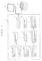
Fig.1 is a block diagram that shows an example of a structure of a perimeter according to the invention; -
Fig.2 is a typical view showing an example of the structure of the perimeter (especially, a portion of stimulus presentation means) according to the invention; -
Fig.3 is a view of an example of a characteristic curve obtained by conducting perimetry on many (two or more) persons having normal eyes; -
Fig.4 is a view of an example of a graph outputted through the perimeter according to the invention; -
Fig.5 is a typical view of an example of a structure of the perimeter; -
Fig. 6 is a view showing an example of a change of MD value with time; and -
Fig.7(a) is a view showing an example of the characteristic curve obtained by conducting perimetry on many (two or more) persons having normal eyes, andFig.7 (b) is a view showing a relation between a position in a visual field and sensitivity. - An embodiment of the invention is mentioned, referring to appended figures
Figs.1 to 4 . - A perimeter according to the invention is constructed so as to test a visual field of an examinee in such a state that the examinee fixates a predetermined fixation target, such as a center point of a
visual field dome 20B shown inFig.2 ). Such a perimeter is exemplarily shown with areference number 1 inFig.1 orFig.2 , and has stimulus presentation means 2 (will be mentioned in detail) for presenting a stimulus A having predetermined luminance at a plurality of peripheral positions of the fixation target ("the position where the stimulus should be presented" in the specification) in order. - Such an
perimeter 1 is provided with response means 3, such as a push switch. If the examinee who perceived the presented stimulus A (or an examiner watching a response of the examinee) operates the response means 3, response signals (that is, signals showing that the examinee actually perceived the presented stimulus) can be inputted into the perimeter 1 (concretely speaking, into luminance judging means 4). - The
perimeter 1 according to the invention has luminance judging means 4 for judging luminance of the stimulus which the examinee perceived for each position where stimulus should be presented based upon signals from the stimulus presentation means 2 and the response means 3. Such luminance judging means 4 may output a difference between "luminance that is some standard (standard luminance)" and "measurement luminance (that is, the luminance of the stimulus which the examinee actually perceived)". - There is an individual difference between persons having normal eyes in the luminance of the stimulus that can be perceived. Such an individual difference appears as a characteristic curve as shown in
Fig.3 if perimetry is conducted on many (a plurality of) persons having normal eyes and data are collected. A transverse axis ofFig.3 shows sensitivity (that is, a value in connection with the luminance of the presented stimulus, and concretely speaking, a difference between the standard luminance and the measurement luminance) and a longitudinal axis shows a number of persons who have perceived the stimulus. In the specification, any one of (1) a value based upon the luminance of the stimulus which the most persons have perceived (see a reference mark S0), (2) a value based upon an average value obtained by dividing the perceived luminance by number of persons, (3) a value based upon the luminance of the stimulus which an almost middle rank of person have perceived if the persons who have perceived the stimulus are ranked based upon the perceived luminance (for example, the sensitivity of the 50th person from the person having the best sensitivity, if perimetry is conducted on a hundred ofpersons), and (4) a value that is the other standard excluding the above-mentioned values, such as the sensitivity of the n-th person from the upper ranked person, is defined as "a normal value (corresponds to "a representative value" in claims)". In other words, "the normal value (the representative value) of the luminance of the stimulus to be perceived by normal eyes" is statistically obtained in the above-mentioned way in the invention. Since the above-mentioned characteristic curve is obtained by presenting the stimulus to the same position (the same position where the stimulus should be presented) betweenmanypersons, the other characteristic curve is obtained in the other position where the stimulus should be presented. So, the normal value (the representative value) is also different, depending on the position where the stimulus should be presented. Theperimeter 1 according to the invention has normal value storing means 5 (represetative value storing means) for storing the normal value for each position where the stimulus should be presented as data. - On the other hand, the sensitivity through which number of measured persons can be distributed at a constant rate (see S1 in
Fig.3 ) in the above-mentioned characteristic curve is referred to as "a critical value (p value)" in the specification. For example, a critical value S1 as shown inFig.3 shows such a sensitivity that 95 percent of the persons are within a right side range (good sensitivity side) and 5 percent of the persons are within a left side region (poor sensitivity side). In the specification, such a p value (the p value wherein 5 percent of the persons are within the poor sensitivity side) is referred to as "p value = 5% , if necessary. In other words, if the sensitivity in p value =5% is 3dB, 95 percent of the persons can perceive the stimulus brighter than 3dB. The p value is different, depending on the position where the stimulus should be presented, but theperimeter 1 according to the invention has p value storing means 6 (critical value storing means) for storing p values for respective positions where the stimulus should be presented as data. - On the other hand, the perimeter according to the invention has sensitivity deviation computing means 7 for computing a sensitivity deviation for each position where the stimulus should be presented from signals from the luminance judging means 4 and data of the normal value storing means 5 (that is, the normal value for each position where the stimulus should be presented). Such a sensitivity deviation is a concept including a total deviation and a pattern deviation, and means a difference between a value regarding the luminance of the stimulus which the examinee actually perceived (the luminance itself or the above-mentioned sensitivity) and the above-mentioned normal value (the luminance itself or the above-mentioned sensitivity).
- Furthermore, the
perimeter 1 according to the invention has means for computing ratio to p value 8 (means for computing ratio to critical value), which computes "ratio to p value (corresponds ratio to critical value in claims)" that is a ratio between the p value and the sensitivity deviation for each position where the stimulus should be presented. Such means for computing ratio top value 8 may obtain a ratio of "p value ratio/sensitivity deviation or may obtain its inverse number (that is, the ratio of "sensitivity deviation/p value ratio"). In a case where p value =5% is 3dB in some position where the stimulus should be presented and the sensitivity deviation of some examinee in the position where the stimulus should be presented is 1.5dB, the computed ratio to p value is 0.5 (or its inverse number 2). The ratio computed through means for computing ratio top value 8 may not be such a ratio (the ratio in a strict meaning), but may be "some function between the sensitivity deviation and the p value" that changes due to the change of the sensitivity deviation. - In addition, the
perimeter 1 according to the invention has means for adding ratios to p value (means for adding ratios to critical value) 9, which computes a total value of ratios to p value computed for respective positions where the stimulus should be presented or an average value obtained by dividing the total value by the number of the positions where the stimulus should be presented. The means for adding ratios to p value 9 includes means for obtaining the total value and the average value and also includes means for obtaining some value equivalent thereto. If the ratio to p value in each position where the stimulus should be presented is B1, B2 and B3, the concept of "the total value of the ratios to p value or the average value obtained by dividing the total value by the number of the positions where the stimulus should be presented" also includes some value obtained by using the ratio to p value of each position where the stimulus should be presented that is influenced by the change of any of the ratio to p value as well as the total value of the ratios to p value "B1 + B2 + B3+..." and the average value of the ratios to p value "(B1 + B2 + B3 +...) /n". For example, a value obtained by multiplying the ratio to p value by coefficient for weight C1, ..., such as C1*B1 + C2*B2 +C3*B3 +... and (C1*B1 + C2*B2 +C3*B3 + ...)/n, is also included therein. - As shown in
Fig.7(b) , a sensitivity dispersion region is different, depending on the positions where sensitivity is measured (that is, the position where the stimulus should be presented), and has an inclination to be the smallest in a center position of the visual field and to become bigger as the peripheral region of the visual field draws close. The above-mentioned p value (the critical value) is the value in connection with "change of the sensitivity dispersion region", and "the ratio to p value" and "the total value or the average value of the ratio to p value" is the value adding an element, "change of the sensitivity dispersion region" thereto. In other words, in a case where the sensitivity deviation at a position where p value =5% is -10dB, such as a peripheral portion of the visual field, is lowered by 1dB, the ratio to p value (= sensitivity deviation /p value) becomes -0.1. In a case where the sensitivity deviation at a position where p value =5% is -2dB, such as a central portion of the visual field is lowered by 1dB, the ratio to p value (= sensitivity deviation /p value) becomes -0.5. Even if a degree of lowering the sensitivity deviation is the same, the numeral value (absolute value) becomes bigger if it is lowered at the central portion of the visual field and the total value or the average value of the ratio to p value is widely changed. Then, it is possible to judge as to whether it is important or not by watching changes of the total value or the average value of the ratio to p value with time even if the same amount of sensitivity deviation is lowered. - In this case, it is preferable to provide test result storing means 10 that stores the total value or the average value computed by the means for adding ratios to p value 9 as well as examinee ID for identification of the examinee, and change output means 11 for outputting changes with time of the total value or the average value of the examinee, and to show a graph or a table on a
printer 12 or a monitor 13 (seeFig.4 ). - On the other hand, a method of controlling the
perimeter 1 has
a step of presenting the stimulus A having predetermined luminance in order to a plurality of positions where the stimulus should be presented through the stimulus presentation means 2;
a step of judging the luminance of the stimulus perceived by the examinee for each position where the stimulus should be presented through the luminance judging means 4 based upon response signals showing that the examinee has perceived the presented stimulus (that is, the response signals from the response means 3) and signals from the stimulus presentation means 2;
a step of computing the sensitivity deviation which is a difference between the value regarding the luminance of the stimulus perceived by the examinee and the normal value through the sensitivity deviation computing means 7 for each position where the stimulus should be presented based upon "the normal value of the luminance of the stimulus to be perceived with normal eyes" that is stored in the normal value storing means 5 as data in connection with each position where each stimulus should be presented and the signals from the luminance judging means 4; and
a step of computing "the ratio to p value" that is the ratio between "the p value that is the critical value of the luminance of the stimulus perceived by a predetermined rate of normal eyes" that is stored in the p value storing means 6 as data in connection with each position where the stimulus should be presented and the sensitivity deviation computed by the sensitivity deviation computing means 7 for each position where the stimulus should be presented through means for computing ratio top value 8; and
a step of computing the total value of the ratios to p value computed for respective positions where the stimulus should be presented or the average value obtained by dividing the total value by the number of positions where the stimulus should be presented through means for adding ratios to p value 9. - In such a case, the above-mentioned method may have a step of storing the total value or the average value that is computed by means of adding ratios to p value 9 through the test result storing means 10 as well as the examinee ID for identification of each examinee, and
a step of outputting the change of the total value or the average value of the examinee with time through change output means 11. - A structure of the stimulus presentation means 2 as shown in
Fig.2 is mentioned briefly. - A
reference number 20 in the figure denotes the stimulus presentation portion for presenting stimulus A in the visual field of the examinee, areference numeral 21 denotes the presentation portion changing portion for changing the portion where the stimulus A is presented and areference numeral 22 denotes the luminance setting portion for setting the luminance of the stimulus A. - The
stimulus presentation portion 20 in the figure is comprised of a projectionoptical system 20A for projecting stimuli andprojection member 20B where stimuli are projected by the projectionoptical system 20A, but may have any structure as long as thestimulus presentation portion 20 can present the stimuli in the visual field of the examinee. For example, a plurality of LEDs may be located and be selectively lighted. Theprojection member 20B inFig.2 has a semi-spherical dome shape (visual field dome), but may have a shape with a curved face excluding a semi-sphere or a shape with a plane. - If the
stimulus presentation portion 20 is comprised of the projectionoptical system 20A and theprojection member 20B as shown inFig.2 , the presentationportion changing portion 21 may be comprised of driving means for changing positions of structural elements of the projectionoptical system 20A, such as projector mirrors 211, 212 (not shown). If the stimulus presentation portion is comprised of a plurality of LEDs, which LED should be lighted may be controlled by the presentation portion changing portion. Even if any of the projection optical system and LED is used, an examiner may manually instruct to change the portion to be presented with a touch pen, a mouse or a keyboard, watching a display, or the change of the portion to be presented may be automatically instructed through a program prepared in advance. - The
luminance setting portion 22 as shown inFig.2 is comprised ofturrets driving mechanism 223 for changing positions of theturrets - The present invention has been explained on the basis of the example embodiments discussed. Although some variations have been mentioned, the embodiments which are described in the specification are illustrative and not limiting. The scope of the invention is designated by the accompanying claims and is not restricted by the descriptions of the specific embodiments. Accordingly, all the transformations and changes within the scope of the claims are to be construed as included in the scope of the present invention.
Claims (5)
- A perimeter for testing a visual field of an examinee in such a state the examinee fixates a predetermined fixation target, comprising:stimulus presentation means for presenting a stimulus having predetermined luminance in order at a plurality of positions where stimulus should be presented in a periphery of said fixation target;response means through which an examiner or the examinee inputs response signals showing that the examinee actually perceived the presented stimulus;luminance judging means for judging said luminance of said stimulus perceived by the examinee for each position where said stimulus should be presented based upon signals from said stimulus presentation means and said response means;representative value storing means for storing "a representative value of the luminance of the stimulus to be perceived with normal eyes" statistically obtained in perimetry that is conducted on a plurality of persons having normal eyes as data in connection with each position where the stimulus should be presented;critical value storing means for storing "a critical value that shows a boundary of the luminance of the stimulus perceived by a predetermined rate of normal eyes" statistically obtained in perimetry that is conducted on a plurality of persons having normal eyes as data in connection with each position where the stimulus should be presented;sensitivity deviation computing means for computing sensitivity deviation that is a difference between a value in connection with the luminance of the stimulus perceived by the examinee and said representative value for each position where the stimulus should be presented based upon said signals from said luminance judging means and said data of said representative value storing means;means for computing ratio to critical value which computes "a ratio to critical value" that is a ratio between a critical value stored in said critical value storing means and said sensitivity deviation computed by said sensitivity deviation computing means for each position where the stimulus should be presented; andmeans for adding ratios to critical value, which computes a total value of said ratios to critical value computed for each position where the stimulus should be presented or an average value obtained by dividing said total value by number of positions where the stimulus should be presented.
- The perimeter according to claim 1, wherein said representative value is a value determined from a characteristic curve that shows a relation between "the luminance of the stimulus" obtained by conducting perimetry on a plurality of persons having normal eyes and "number of persons who actually perceived the stimulus having the luminance, and is the value based upon the luminance of the stimulus perceived by the most persons, a value based upon an average value obtained by dividing the perceived luminance by a number of said persons, or a value based upon the luminance of the stimulus perceived by almost middle rank of person when said persons are ranked based upon the perceived luminance.
- The perimeter according to any one of the preceding claims, further comprising:test result storing means for storing said total value or said average value computed by said means for adding ratios to critical value as well as examinee ID for identification of the examinees; andchange output means for outputting changes with time in the total value or the average value of the examinee.
- A method of controlling a perimeter, comprising:a step of presenting a stimulus having predetermined luminance in order to a plurality of positions where the stimulus should be presented through stimulus presentation means;a step of judging the luminance of the stimulus perceived by the examinee for each position where the stimulus should be presented through luminance judging means based upon response signals showing that the examinee has perceived the presented stimulus and signals from the stimulus presentation means;a step of computing sensitivity deviation which is a difference between a value regarding the luminance of the stimulus perceived by the examinee and the representative value through sensitivity deviation computing means for each position where the stimulus should be presented based upon "a representative value of the luminance of the stimulus to be perceived with normal eyes" that is stored in representative value storing means as data in connection with each position where each stimulus should be presented and the signals from the luminance judging means;a step of computing "a ratio to critical value" that is the ratio between "a critical value that is a boundary of the luminance of the stimulus perceived by a predetermined rate of normal eyes" that is stored in critical value storing means as data in connection with each position where the stimulus should be presented and the sensitivity deviation computed by the sensitivity deviation computing means for each position where the stimulus should be presented through means for computing ratio to critical value; anda step of computing a total value of ratios to critical value computed for respective positions where the stimulus should be presented or an average value obtained by dividing the total value by number of positions where the stimulus should be presented through means for adding ratios to critical value.
- The method of controlling the perimeter according to claim 4, further comprising:a step of storing the total value or the average value that is computed by means of adding ratios to critical value through the test result storing means as well as the examinee ID for identification of each examinee, anda step of outputting change of the total value or the average value of the examinee with time through change output means.
Applications Claiming Priority (1)
| Application Number | Priority Date | Filing Date | Title |
|---|---|---|---|
| JP2010074729A JP5451484B2 (en) | 2010-03-29 | 2010-03-29 | Perimeter and perimeter control method |
Publications (2)
| Publication Number | Publication Date |
|---|---|
| EP2371269A1 true EP2371269A1 (en) | 2011-10-05 |
| EP2371269B1 EP2371269B1 (en) | 2013-03-27 |
Family
ID=44260180
Family Applications (1)
| Application Number | Title | Priority Date | Filing Date |
|---|---|---|---|
| EP11152283A Not-in-force EP2371269B1 (en) | 2010-03-29 | 2011-01-26 | Perimeter and method of controlling perimeter |
Country Status (3)
| Country | Link |
|---|---|
| US (1) | US8157379B2 (en) |
| EP (1) | EP2371269B1 (en) |
| JP (1) | JP5451484B2 (en) |
Families Citing this family (2)
| Publication number | Priority date | Publication date | Assignee | Title |
|---|---|---|---|---|
| US9622653B2 (en) * | 2012-08-10 | 2017-04-18 | Kowa Company, Ltd | Perimeter |
| US20160345823A1 (en) * | 2014-02-12 | 2016-12-01 | Kowa Company, Ltd | Perimeter |
Citations (4)
| Publication number | Priority date | Publication date | Assignee | Title |
|---|---|---|---|---|
| US6386706B1 (en) * | 1996-07-31 | 2002-05-14 | Virtual-Eye.Com | Visual function testing with virtual retinal display |
| JP2002272685A (en) | 2001-03-15 | 2002-09-24 | Kowa Co | Ophthalmic measurement device |
| US20070177105A1 (en) * | 2006-01-27 | 2007-08-02 | Satoshi Shimada | Perimeter |
| JP2010074729A (en) | 2008-09-22 | 2010-04-02 | Kddi Corp | Radio wave propagation property estimation apparatus and computer program |
Family Cites Families (6)
| Publication number | Priority date | Publication date | Assignee | Title |
|---|---|---|---|---|
| US5864384A (en) * | 1996-07-31 | 1999-01-26 | Mcclure; Richard J. | Visual field testing method and apparatus using virtual reality |
| JP4250048B2 (en) * | 2003-09-30 | 2009-04-08 | 株式会社ニデック | Perimeter |
| JP4458935B2 (en) * | 2004-06-01 | 2010-04-28 | 株式会社ニデック | Perimeter |
| JP5008540B2 (en) * | 2007-12-05 | 2012-08-22 | 興和株式会社 | Ophthalmic equipment |
| JP4205150B1 (en) * | 2008-09-05 | 2009-01-07 | 知博 蔦 | Perimeter |
| JP5624272B2 (en) * | 2008-10-06 | 2014-11-12 | 興和株式会社 | Perimeter |
-
2010
- 2010-03-29 JP JP2010074729A patent/JP5451484B2/en not_active Expired - Fee Related
- 2010-08-25 US US12/868,174 patent/US8157379B2/en not_active Expired - Fee Related
-
2011
- 2011-01-26 EP EP11152283A patent/EP2371269B1/en not_active Not-in-force
Patent Citations (4)
| Publication number | Priority date | Publication date | Assignee | Title |
|---|---|---|---|---|
| US6386706B1 (en) * | 1996-07-31 | 2002-05-14 | Virtual-Eye.Com | Visual function testing with virtual retinal display |
| JP2002272685A (en) | 2001-03-15 | 2002-09-24 | Kowa Co | Ophthalmic measurement device |
| US20070177105A1 (en) * | 2006-01-27 | 2007-08-02 | Satoshi Shimada | Perimeter |
| JP2010074729A (en) | 2008-09-22 | 2010-04-02 | Kddi Corp | Radio wave propagation property estimation apparatus and computer program |
Also Published As
| Publication number | Publication date |
|---|---|
| EP2371269B1 (en) | 2013-03-27 |
| US8157379B2 (en) | 2012-04-17 |
| JP2011206144A (en) | 2011-10-20 |
| JP5451484B2 (en) | 2014-03-26 |
| US20110234980A1 (en) | 2011-09-29 |
Similar Documents
| Publication | Publication Date | Title |
|---|---|---|
| US10835117B2 (en) | Testing and determining a threshold value | |
| US12471771B2 (en) | Visual testing using mobile devices | |
| US9433346B2 (en) | Circular preferential hyperacuity perimetry video game to monitor macular and retinal diseases | |
| Ansari et al. | Psychophysical characterisation of early functional loss in glaucoma and ocular hypertension | |
| KR20140111298A (en) | Video game to monitor visual field loss in glaucoma | |
| AU2012340573A1 (en) | Video game to monitor retinal diseases | |
| EP2172148A1 (en) | Perimeter | |
| US6129436A (en) | Method and device for visual examination | |
| WO2016046202A1 (en) | Visual field measuring device and system | |
| US12137975B2 (en) | Systems, methods, and program products for performing on-off perimetry visual field tests | |
| EP2371269B1 (en) | Perimeter and method of controlling perimeter | |
| WO2009075385A1 (en) | Visual field examining method and apparatus | |
| US8727535B2 (en) | Perimeter and method of controlling perimeter | |
| CN118614859A (en) | A new type of ophthalmic examination instrument | |
| US12114928B2 (en) | Ocular focus assessment and monitoring for myopia and other vision disorders | |
| US10143367B2 (en) | Instrument and method for visual field examination | |
| JP2824788B2 (en) | Static perimeter | |
| JP7274446B2 (en) | Vision inspection device, vision inspection system and vision inspection program | |
| WO2022024417A1 (en) | Vision testing device, vision testing system, and vision testing program | |
| Skalka et al. | Contrast sensitivity testing in patients with juvenile diabetes | |
| Leisman | The Examination of Fixation Locus in Scanning a Visual Display |
Legal Events
| Date | Code | Title | Description |
|---|---|---|---|
| PUAI | Public reference made under article 153(3) epc to a published international application that has entered the european phase |
Free format text: ORIGINAL CODE: 0009012 |
|
| AK | Designated contracting states |
Kind code of ref document: A1 Designated state(s): AL AT BE BG CH CY CZ DE DK EE ES FI FR GB GR HR HU IE IS IT LI LT LU LV MC MK MT NL NO PL PT RO RS SE SI SK SM TR |
|
| AX | Request for extension of the european patent |
Extension state: BA ME |
|
| 17P | Request for examination filed |
Effective date: 20120113 |
|
| GRAP | Despatch of communication of intention to grant a patent |
Free format text: ORIGINAL CODE: EPIDOSNIGR1 |
|
| GRAS | Grant fee paid |
Free format text: ORIGINAL CODE: EPIDOSNIGR3 |
|
| GRAA | (expected) grant |
Free format text: ORIGINAL CODE: 0009210 |
|
| AK | Designated contracting states |
Kind code of ref document: B1 Designated state(s): AL AT BE BG CH CY CZ DE DK EE ES FI FR GB GR HR HU IE IS IT LI LT LU LV MC MK MT NL NO PL PT RO RS SE SI SK SM TR |
|
| REG | Reference to a national code |
Ref country code: GB Ref legal event code: FG4D |
|
| REG | Reference to a national code |
Ref country code: CH Ref legal event code: EP |
|
| REG | Reference to a national code |
Ref country code: AT Ref legal event code: REF Ref document number: 602839 Country of ref document: AT Kind code of ref document: T Effective date: 20130415 |
|
| REG | Reference to a national code |
Ref country code: IE Ref legal event code: FG4D |
|
| REG | Reference to a national code |
Ref country code: DE Ref legal event code: R096 Ref document number: 602011001134 Country of ref document: DE Effective date: 20130529 |
|
| PG25 | Lapsed in a contracting state [announced via postgrant information from national office to epo] |
Ref country code: LT Free format text: LAPSE BECAUSE OF FAILURE TO SUBMIT A TRANSLATION OF THE DESCRIPTION OR TO PAY THE FEE WITHIN THE PRESCRIBED TIME-LIMIT Effective date: 20130327 Ref country code: NO Free format text: LAPSE BECAUSE OF FAILURE TO SUBMIT A TRANSLATION OF THE DESCRIPTION OR TO PAY THE FEE WITHIN THE PRESCRIBED TIME-LIMIT Effective date: 20130627 Ref country code: SE Free format text: LAPSE BECAUSE OF FAILURE TO SUBMIT A TRANSLATION OF THE DESCRIPTION OR TO PAY THE FEE WITHIN THE PRESCRIBED TIME-LIMIT Effective date: 20130327 Ref country code: BG Free format text: LAPSE BECAUSE OF FAILURE TO SUBMIT A TRANSLATION OF THE DESCRIPTION OR TO PAY THE FEE WITHIN THE PRESCRIBED TIME-LIMIT Effective date: 20130627 |
|
| REG | Reference to a national code |
Ref country code: AT Ref legal event code: MK05 Ref document number: 602839 Country of ref document: AT Kind code of ref document: T Effective date: 20130327 |
|
| REG | Reference to a national code |
Ref country code: LT Ref legal event code: MG4D |
|
| PG25 | Lapsed in a contracting state [announced via postgrant information from national office to epo] |
Ref country code: SI Free format text: LAPSE BECAUSE OF FAILURE TO SUBMIT A TRANSLATION OF THE DESCRIPTION OR TO PAY THE FEE WITHIN THE PRESCRIBED TIME-LIMIT Effective date: 20130327 Ref country code: GR Free format text: LAPSE BECAUSE OF FAILURE TO SUBMIT A TRANSLATION OF THE DESCRIPTION OR TO PAY THE FEE WITHIN THE PRESCRIBED TIME-LIMIT Effective date: 20130628 Ref country code: FI Free format text: LAPSE BECAUSE OF FAILURE TO SUBMIT A TRANSLATION OF THE DESCRIPTION OR TO PAY THE FEE WITHIN THE PRESCRIBED TIME-LIMIT Effective date: 20130327 Ref country code: LV Free format text: LAPSE BECAUSE OF FAILURE TO SUBMIT A TRANSLATION OF THE DESCRIPTION OR TO PAY THE FEE WITHIN THE PRESCRIBED TIME-LIMIT Effective date: 20130327 |
|
| REG | Reference to a national code |
Ref country code: NL Ref legal event code: VDEP Effective date: 20130327 |
|
| PG25 | Lapsed in a contracting state [announced via postgrant information from national office to epo] |
Ref country code: HR Free format text: LAPSE BECAUSE OF FAILURE TO SUBMIT A TRANSLATION OF THE DESCRIPTION OR TO PAY THE FEE WITHIN THE PRESCRIBED TIME-LIMIT Effective date: 20130327 Ref country code: BE Free format text: LAPSE BECAUSE OF FAILURE TO SUBMIT A TRANSLATION OF THE DESCRIPTION OR TO PAY THE FEE WITHIN THE PRESCRIBED TIME-LIMIT Effective date: 20130327 |
|
| PG25 | Lapsed in a contracting state [announced via postgrant information from national office to epo] |
Ref country code: IS Free format text: LAPSE BECAUSE OF FAILURE TO SUBMIT A TRANSLATION OF THE DESCRIPTION OR TO PAY THE FEE WITHIN THE PRESCRIBED TIME-LIMIT Effective date: 20130727 Ref country code: CZ Free format text: LAPSE BECAUSE OF FAILURE TO SUBMIT A TRANSLATION OF THE DESCRIPTION OR TO PAY THE FEE WITHIN THE PRESCRIBED TIME-LIMIT Effective date: 20130327 Ref country code: ES Free format text: LAPSE BECAUSE OF FAILURE TO SUBMIT A TRANSLATION OF THE DESCRIPTION OR TO PAY THE FEE WITHIN THE PRESCRIBED TIME-LIMIT Effective date: 20130708 Ref country code: NL Free format text: LAPSE BECAUSE OF FAILURE TO SUBMIT A TRANSLATION OF THE DESCRIPTION OR TO PAY THE FEE WITHIN THE PRESCRIBED TIME-LIMIT Effective date: 20130327 Ref country code: RO Free format text: LAPSE BECAUSE OF FAILURE TO SUBMIT A TRANSLATION OF THE DESCRIPTION OR TO PAY THE FEE WITHIN THE PRESCRIBED TIME-LIMIT Effective date: 20130327 Ref country code: PT Free format text: LAPSE BECAUSE OF FAILURE TO SUBMIT A TRANSLATION OF THE DESCRIPTION OR TO PAY THE FEE WITHIN THE PRESCRIBED TIME-LIMIT Effective date: 20130729 Ref country code: SK Free format text: LAPSE BECAUSE OF FAILURE TO SUBMIT A TRANSLATION OF THE DESCRIPTION OR TO PAY THE FEE WITHIN THE PRESCRIBED TIME-LIMIT Effective date: 20130327 Ref country code: AT Free format text: LAPSE BECAUSE OF FAILURE TO SUBMIT A TRANSLATION OF THE DESCRIPTION OR TO PAY THE FEE WITHIN THE PRESCRIBED TIME-LIMIT Effective date: 20130327 Ref country code: EE Free format text: LAPSE BECAUSE OF FAILURE TO SUBMIT A TRANSLATION OF THE DESCRIPTION OR TO PAY THE FEE WITHIN THE PRESCRIBED TIME-LIMIT Effective date: 20130327 |
|
| PG25 | Lapsed in a contracting state [announced via postgrant information from national office to epo] |
Ref country code: CY Free format text: LAPSE BECAUSE OF FAILURE TO SUBMIT A TRANSLATION OF THE DESCRIPTION OR TO PAY THE FEE WITHIN THE PRESCRIBED TIME-LIMIT Effective date: 20130327 Ref country code: PL Free format text: LAPSE BECAUSE OF FAILURE TO SUBMIT A TRANSLATION OF THE DESCRIPTION OR TO PAY THE FEE WITHIN THE PRESCRIBED TIME-LIMIT Effective date: 20130327 |
|
| PG25 | Lapsed in a contracting state [announced via postgrant information from national office to epo] |
Ref country code: DK Free format text: LAPSE BECAUSE OF FAILURE TO SUBMIT A TRANSLATION OF THE DESCRIPTION OR TO PAY THE FEE WITHIN THE PRESCRIBED TIME-LIMIT Effective date: 20130327 |
|
| PLBE | No opposition filed within time limit |
Free format text: ORIGINAL CODE: 0009261 |
|
| STAA | Information on the status of an ep patent application or granted ep patent |
Free format text: STATUS: NO OPPOSITION FILED WITHIN TIME LIMIT |
|
| PG25 | Lapsed in a contracting state [announced via postgrant information from national office to epo] |
Ref country code: IT Free format text: LAPSE BECAUSE OF FAILURE TO SUBMIT A TRANSLATION OF THE DESCRIPTION OR TO PAY THE FEE WITHIN THE PRESCRIBED TIME-LIMIT Effective date: 20130327 |
|
| 26N | No opposition filed |
Effective date: 20140103 |
|
| REG | Reference to a national code |
Ref country code: DE Ref legal event code: R097 Ref document number: 602011001134 Country of ref document: DE Effective date: 20140103 |
|
| PG25 | Lapsed in a contracting state [announced via postgrant information from national office to epo] |
Ref country code: LU Free format text: LAPSE BECAUSE OF FAILURE TO SUBMIT A TRANSLATION OF THE DESCRIPTION OR TO PAY THE FEE WITHIN THE PRESCRIBED TIME-LIMIT Effective date: 20140126 |
|
| REG | Reference to a national code |
Ref country code: CH Ref legal event code: PL |
|
| PG25 | Lapsed in a contracting state [announced via postgrant information from national office to epo] |
Ref country code: LI Free format text: LAPSE BECAUSE OF NON-PAYMENT OF DUE FEES Effective date: 20140131 Ref country code: CH Free format text: LAPSE BECAUSE OF NON-PAYMENT OF DUE FEES Effective date: 20140131 |
|
| REG | Reference to a national code |
Ref country code: FR Ref legal event code: ST Effective date: 20140930 |
|
| REG | Reference to a national code |
Ref country code: IE Ref legal event code: MM4A |
|
| PG25 | Lapsed in a contracting state [announced via postgrant information from national office to epo] |
Ref country code: FR Free format text: LAPSE BECAUSE OF NON-PAYMENT OF DUE FEES Effective date: 20140131 |
|
| PG25 | Lapsed in a contracting state [announced via postgrant information from national office to epo] |
Ref country code: IE Free format text: LAPSE BECAUSE OF NON-PAYMENT OF DUE FEES Effective date: 20140126 |
|
| PG25 | Lapsed in a contracting state [announced via postgrant information from national office to epo] |
Ref country code: MC Free format text: LAPSE BECAUSE OF FAILURE TO SUBMIT A TRANSLATION OF THE DESCRIPTION OR TO PAY THE FEE WITHIN THE PRESCRIBED TIME-LIMIT Effective date: 20130327 |
|
| PG25 | Lapsed in a contracting state [announced via postgrant information from national office to epo] |
Ref country code: MT Free format text: LAPSE BECAUSE OF FAILURE TO SUBMIT A TRANSLATION OF THE DESCRIPTION OR TO PAY THE FEE WITHIN THE PRESCRIBED TIME-LIMIT Effective date: 20130327 |
|
| PG25 | Lapsed in a contracting state [announced via postgrant information from national office to epo] |
Ref country code: SM Free format text: LAPSE BECAUSE OF FAILURE TO SUBMIT A TRANSLATION OF THE DESCRIPTION OR TO PAY THE FEE WITHIN THE PRESCRIBED TIME-LIMIT Effective date: 20130327 |
|
| PG25 | Lapsed in a contracting state [announced via postgrant information from national office to epo] |
Ref country code: RS Free format text: LAPSE BECAUSE OF FAILURE TO SUBMIT A TRANSLATION OF THE DESCRIPTION OR TO PAY THE FEE WITHIN THE PRESCRIBED TIME-LIMIT Effective date: 20130327 |
|
| PG25 | Lapsed in a contracting state [announced via postgrant information from national office to epo] |
Ref country code: HU Free format text: LAPSE BECAUSE OF FAILURE TO SUBMIT A TRANSLATION OF THE DESCRIPTION OR TO PAY THE FEE WITHIN THE PRESCRIBED TIME-LIMIT; INVALID AB INITIO Effective date: 20110126 Ref country code: TR Free format text: LAPSE BECAUSE OF FAILURE TO SUBMIT A TRANSLATION OF THE DESCRIPTION OR TO PAY THE FEE WITHIN THE PRESCRIBED TIME-LIMIT Effective date: 20130327 |
|
| PG25 | Lapsed in a contracting state [announced via postgrant information from national office to epo] |
Ref country code: MK Free format text: LAPSE BECAUSE OF FAILURE TO SUBMIT A TRANSLATION OF THE DESCRIPTION OR TO PAY THE FEE WITHIN THE PRESCRIBED TIME-LIMIT Effective date: 20130327 |
|
| PG25 | Lapsed in a contracting state [announced via postgrant information from national office to epo] |
Ref country code: AL Free format text: LAPSE BECAUSE OF FAILURE TO SUBMIT A TRANSLATION OF THE DESCRIPTION OR TO PAY THE FEE WITHIN THE PRESCRIBED TIME-LIMIT Effective date: 20130327 |
|
| PGFP | Annual fee paid to national office [announced via postgrant information from national office to epo] |
Ref country code: GB Payment date: 20221208 Year of fee payment: 13 |
|
| PGFP | Annual fee paid to national office [announced via postgrant information from national office to epo] |
Ref country code: DE Payment date: 20221130 Year of fee payment: 13 |
|
| REG | Reference to a national code |
Ref country code: DE Ref legal event code: R119 Ref document number: 602011001134 Country of ref document: DE |
|
| GBPC | Gb: european patent ceased through non-payment of renewal fee |
Effective date: 20240126 |
|
| PG25 | Lapsed in a contracting state [announced via postgrant information from national office to epo] |
Ref country code: DE Free format text: LAPSE BECAUSE OF NON-PAYMENT OF DUE FEES Effective date: 20240801 |
|
| PG25 | Lapsed in a contracting state [announced via postgrant information from national office to epo] |
Ref country code: GB Free format text: LAPSE BECAUSE OF NON-PAYMENT OF DUE FEES Effective date: 20240126 |
|
| PG25 | Lapsed in a contracting state [announced via postgrant information from national office to epo] |
Ref country code: GB Free format text: LAPSE BECAUSE OF NON-PAYMENT OF DUE FEES Effective date: 20240126 Ref country code: DE Free format text: LAPSE BECAUSE OF NON-PAYMENT OF DUE FEES Effective date: 20240801 |