EP2371232A2 - Insert for a carrying strap - Google Patents
Insert for a carrying strap Download PDFInfo
- Publication number
- EP2371232A2 EP2371232A2 EP11159962A EP11159962A EP2371232A2 EP 2371232 A2 EP2371232 A2 EP 2371232A2 EP 11159962 A EP11159962 A EP 11159962A EP 11159962 A EP11159962 A EP 11159962A EP 2371232 A2 EP2371232 A2 EP 2371232A2
- Authority
- EP
- European Patent Office
- Prior art keywords
- section
- insert
- limitation
- carrying strap
- elastic
- Prior art date
- Legal status (The legal status is an assumption and is not a legal conclusion. Google has not performed a legal analysis and makes no representation as to the accuracy of the status listed.)
- Granted
Links
Images

Classifications
-
- A—HUMAN NECESSITIES
- A45—HAND OR TRAVELLING ARTICLES
- A45F—TRAVELLING OR CAMP EQUIPMENT: SACKS OR PACKS CARRIED ON THE BODY
- A45F3/00—Travelling or camp articles; Sacks or packs carried on the body
- A45F3/04—Sacks or packs carried on the body by means of two straps passing over the two shoulders
-
- A—HUMAN NECESSITIES
- A45—HAND OR TRAVELLING ARTICLES
- A45C—PURSES; LUGGAGE; HAND CARRIED BAGS
- A45C13/00—Details; Accessories
- A45C13/02—Interior fittings; Means, e.g. inserts, for holding and packing articles
-
- A—HUMAN NECESSITIES
- A45—HAND OR TRAVELLING ARTICLES
- A45F—TRAVELLING OR CAMP EQUIPMENT: SACKS OR PACKS CARRIED ON THE BODY
- A45F3/00—Travelling or camp articles; Sacks or packs carried on the body
- A45F3/04—Sacks or packs carried on the body by means of two straps passing over the two shoulders
- A45F3/047—Sacks or packs carried on the body by means of two straps passing over the two shoulders with adjustable fastenings for the shoulder straps or waist belts
-
- A—HUMAN NECESSITIES
- A45—HAND OR TRAVELLING ARTICLES
- A45F—TRAVELLING OR CAMP EQUIPMENT: SACKS OR PACKS CARRIED ON THE BODY
- A45F3/00—Travelling or camp articles; Sacks or packs carried on the body
- A45F3/12—Shoulder-pads
-
- A—HUMAN NECESSITIES
- A45—HAND OR TRAVELLING ARTICLES
- A45F—TRAVELLING OR CAMP EQUIPMENT: SACKS OR PACKS CARRIED ON THE BODY
- A45F3/00—Travelling or camp articles; Sacks or packs carried on the body
- A45F3/12—Shoulder-pads
- A45F2003/122—Back cushioning parts or details of backpacks, e.g. with ventilation
Definitions
- the present invention relates to an insert for a carrying strap for carrying objects by persons.
- Carrying objects is made easier when they can be carried by hand using a handle or when they can be carried at the body using a carrying strap.
- a carrying strap has the advantage that the weight of the object is distributed over larger areas of the body.
- the use of two carrying straps, for example with a backpack, makes it even possible to distribute the weight symmetrically over the body. In this way, heavy loads can be carried.
- the DE 10 2006 007 334 A1 describes a carrying system for a backpack with two shoulder straps. The length of the shoulder straps can be adjusted.
- Carrying an object involves vertical movements and accelerations which results in additional vertical forces which act from the carried object on the body of the carrier of the object. These vertical forces increase when going up a staircase, on uneven ground or when going fast. This force is sensed as a hitch or a hit on the body.
- the present invention is therefore based on the problem to improve an elastic cushioning of a carrying strap so as to limit vertical forces arising from different movements.
- the present invention solves this problem with an insert for a carrying strap for carrying objects at the body according to claim 1.
- the insert comprises an essentially elastic section and a limitation section, wherein a length of the limitation section limits an elongation of the essentially elastic section.
- the length of the limitation section is adjustable.
- a carrying strap comprising such an insert may be used, for example, in a backpack and permits an adjustment of the cushioning to different requirements.
- the vertical elongations of the essentially elastic section may become so large that a reduction of the elongations is desired. According to the invention this can be achieved by adjusting the length of the limitation section which limits an elongation of the essentially elastic section. Conversely, when the load is reduced the length of the limitation section may be increased.
- this elongation can be adjusted by altering the length of the limitation section.
- the limitation section may even be shortened so that the elastic section cannot elongate any more.
- a material is considered “essentially elastic” if it returns to its original state under common loads and forces except for negligible deviations. Accordingly, a material is considered “essentially inelastic” if common loads and forces do not cause a noticeable elongation of the material. Therefore, in the following the term “elastic” will be used instead of “essentially elastic”, and the term “inelastic” will be used instead of “essentially inelastic”.
- the elastic section comprises more than one layer.
- the layers of the elastic section each have different elasticities.
- the layers of the elastic section each comprise different lengths. In this way, an insert may be realized in which the elasticity of the elastic section changes in proportion to the amount by which the elastic section elongates. For example, the force required for elongating the insert may increase stepwise with the elongation.
- the limitation section is formed as a band. It is further preferred that the length of the limitation section is adjusted by means of a ladderlock buckle so that the limitation of the elongation of the insert can be adjusted at any time in a fast and simple manner.
- the limitation section is formed as a cord.
- a change of the length of the cord is greater than the resulting change of the length of the limitation section.
- the force required for an adjustment is therefore lowered, similar to a pulley.
- this enables a more precise adjustment of the limitation of the elongation of the elastic section.
- this is achieved by guiding the cord by inversion points.
- the cord comprises a cord stop or cord lock or slide stop which can be used to adjust the length of the limitation section.
- the cord comprises a hook which can be used for a stepwise adjustment of the length of the limitation section.
- the limitation section comprises an essentially inelastic material. The elongation of the elastic section is therefore limited to the length of the limitation section.
- the limitation section comprises an essentially elastic material.
- the elongation of the elastic section is limited to the elongation of the limitation section.
- the elasticity of the limitation section should be equal to or smaller than the elasticity of the elastic section.
- the invention further comprises a carrying strap having an insert previously described and a backpack or carrying bag with at least one such carrying strap.
- a further embodiment is a backpack or carrying bag which comprises an insert, at least one carrying strap and a side section.
- the insert is arranged between the side section and an end of the at least one carrying strap. Adjusting the cushioning of this backpack or carrying bag therefore only requires an adjustment of a single insert and not of an insert for each carrying strap.
- an insert for a carrying strap of a backpack can be used with bags, carry-seats for babies or other carriers for carrying loads.
- a carrying strap with the insert can be used for carrying any object, for example for carrying sports devices such as a ski bag.
- elastic is understood as “essentially elastic”
- inelastic is understood as “essentially inelastic”.
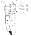
- Fig. 1 shows a first embodiment of an insert 110 of a left carrying strap 120 in a front view 101 and a side view 102 as well as a back view 103 of a backpack 130 with the carrying strap 120.
- the backpack 130 is connected to the carrying strap 120 via a connection section 117 and the insert 110.
- the connection section 117 may comprise an inelastic or an elastic material or a combination of both.
- the insert 110 is arranged in the upper area 115 of the carrying strap 120, i.e. at the end of the carrying strap 120 which is connected to the upper side of the backpack 130.
- One end of the insert 110 is connected to the connection section 117 of the backpack 130, and the other end is connected to the carrying strap 120 in area 116 of carrying strap 120.
- the connection of the insert 110 and the carrying strap 120 will be described in more detail in the following.
- the insert 110 together with the connection section 117 therefore form the connection between the carrying strap 120 and the backpack 130.
- the insert 110 comprises an elastic section 111 which provides cushioning of vertical forces of the backpack 130 on the carrier of the backpack, for example caused by vertical movements during walking. Such movements cause an elongation of the insert 110 and therefore are not directly transferred to the carrying strap 120 and the body, in particular the shoulders, of the carrier of the backpack 130. Rather, the movements are delayed and distributed so that the force exerted on the body is reduced. This improves the wearing comfort.
- the elastic section 111 comprises more than one layer, in particular two layers 111a, 111b. One end of the layers 111a, 111b is connected to the connection section 117, and the other end of the layers 111a, 111b is connected to the carrying strap 120 in the area 116. The position of the area 116 is determined by a length of the elastic section 111.
- the length of the elastic section 111 may vary. In the embodiment of fig. 1 , the length of the elastic section 111 is approximately one third of the length of the carrying strap 120. In other examples, the length of the elastic section 111 may be approximately a half or a quarter of the length of the carrying strap 120.
- a material of the lower layer 111a has a larger elasticity, i.e. a smaller resistance against elongation than a material of the upper layer 111b.
- the lower layer 111a is shorter than the upper layer 111b. Therefore, during an elongation of the elastic section 111 the lower layer 111a is elongated first, and subsequently the upper layer 111b is elongated. The resistance of the elastic section 111 against elongation is therefore increased in a stepwise manner, in proportion to the elongation of the elastic section 111.
- This principle can be transferred in analogy to more than two layers of the elastic section 111.
- the elasticity, width, thickness, and material of layers 111a, 111b may vary.
- the insert 110 further comprises a limitation section 112.
- the limitation section 112 is longer than the lower layer 111a and the upper layer 111b of the elastic section 111.
- One end of the limitation section 112 is connected to the connection section 117, and the other end of the limitation section 112 is connected to the carrying strap 120 in area 118.
- the effective length of the limitation section 112 corresponds to the distance between the two points at which the limitation section 112 is affixed to the carrying strap 120 and the connection section 117 respectively.
- area 118 is arranged approximately in the middle of the carrying strap 120, so that length of the limitation section 112 is approximately half of the length of the carrying strap.
- the length of the limitation section 112 may vary and amounts to, for example, two thirds or one third of the length of the carrying strap 120.
- the limitation section 112 comprises an inelastic material, and therefore the length of the limitation section 112 limits the maximum elongation of the elastic section 111.
- the limitation section may comprise an elastic material the elasticity of which is smaller than the elasticities of the layers 111a, 111b.
- the length of the elongated limitation section 112 limits the elongation of the elastic section 111.
- the limitation section 112 may comprise at one end finger loops for pulling at the limitation section 112 which are not illustrated in fig. 1 . Examples are the finger loops 612a in fig. 6 .
- the width of the lower layer 111a is approximately 5 cm
- the width of the upper layer 111b is approximately 3 cm
- the width of the limitation section 112 formed as a band is approximately 1,5 cm. These values may vary in other embodiments.
- the side view 102 shows the elastic section 111 in a relaxed state in which the layers 111a, 111b have minimal length.
- a part of the elastic section 111 and a part of the limitation section 112 are covered by a cover 121 which is connected to the carrying strap 120 so that it permits sliding of the elastic section 111 and the limitation section 112 under the cover 121.
- Cover 121 therefore protects the elastic section 110 and the limitation section 112 and provides guidance for these sections during their movements.
- ladderlock buckle 119 which can be used to change the length of the limitation section.
- Ladderlock buckle 119 is arranged in the section of limitation section 112 which is not covered by cover 121. Use of a ladderlock buckle 119 and its arrangement at the carrying strap 120 facilitates changing the maximum elongation of the elastic section 111 and thereby of the insert 110 rapidly and at any time, for example during a transition from walking to running.
- the limitation section 112 can be shortened so that it is shorter than or equal to the length of the lower layer 111a. In this case, the elastic section 111 cannot elongate any more. In this position the insert 110 therefore has no elasticity.
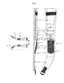
- Fig. 2 shows a second embodiment of an insert 210 of a left carrying strap 220 in a front view 201 and a side view 202 and a back view 203 of a backpack 230 with the carrying strap 220.
- the carrying strap 220 is connected to the backpack 230 via the insert 210 and a connection section 217.
- the connection section 217 is substantially longer than the connection section 117 in Fig. 1 . Therefore, in contrast to Fig. 1 , the insert 210 is arranged in a middle area 215 of the carrying strap 220. Since the connection section 217 overlays carrying strap 220, connection section 217 glides on carrying strap 220 during elongations of the insert 210, rather than on a garment of the carrier of the backpack. This improves the comfort.
- the connection section 217 is guided by guidance 221 which is connected to the carrying strap 220.
- Elastic section 211 of insert 210 comprises more than one layer, in particular three layers which are illustrated in the side view 202 in Fig. 2 . In the embodiment of Fig. 2 these layers have essentially the same length and the same elasticity.
- elastic section 211 has a width of approximately 5 cm and comprises an elastic material. One end of elastic section 211 is connected to the connection section 217, and the other end of elastic section 211 is connected to the carrying strap 220 in the area 216.
- Elastic insert 210 is illustrated in Fig. 2 in a relaxed state.
- Insert 210 further comprises a limitation section 212.
- Adjustment section 212 comprises a cord 212a, preferably an inelastic cord.
- Cord 212a preferably has a diameter of about 3 mm.
- an elastic cord can be used whose elasticity is equal to or smaller than the elasticity of the elastic section 211.
- Two ends of the cord 212a are fixed to the borders of carrying strap 220 in area 216. They run further through loops 219a, which are fixed in area 218 to connection section 217, and through a single loop 219b, which is connected to carrying strap 220 in area 216. Beyond loop 219b cord 212a is held by a slide lock 225.
- the maximum elongation of the insert 210 can be continuously adjusted, and in this position the cord 225 a is fixed using the slide lock 225.
- the slide lock 225 is fixed to the carrying strap 220, for example by sewing.
- the length of the limitation section 212 which limits the elongation of the insert 210 is determined by the distance between the point at which the cord 212a is affixed to the carrying strap 220 in area 216 and the point where the cord 212a runs through the loops 219a, in a tensioned state of the cord 212a.
- the length of the limitation section 212 can be adjusted using cord 212a.
- Loops 219a act as turning points for cord 212a so that limitation section 212 becomes a "pulley". Namely, a reduction of the elongation of elastic section 211 by distance S requires that cord 212a is shortened by distance 2S. This halves the force which is needed for reducing the length of cord 212a, against the weight of the backpack. Conversely, the weight of the backpack can be used for increasing the elongation of insert 210 when the backpack is carried, since the weight acts in the direction of a larger elongation of elastic section 211.
- Fig. 3 illustrates a variant of the second embodiment of Fig. 2 .
- the two ends of cord 312a of limitation section 312 are connected to connection section 217 in area 318. They run further through loops 319a, which are fixed to carrying strap 320 in area 316, and further through a single loop 319b, which is connected to connection section 217 in area 318. Beyond loop 319b cord 312a forms an end which is received by hook 325. Hook 325 can be hooked into loops 326 which are fixed to carrying strap 320 at different distances from loop 319b. This permits a stepwise adjustment of the elongation of insert 310.
- the manner in which the length of limitation section 312 is adjusted is analogous to that described in relation to the embodiment of Fig. 2 .
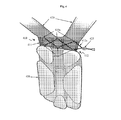
- Fig. 4 illustrates a third embodiment of an insert 410 in a perspective view.
- a single insert 410 is arranged between a side section 430, in particular a back section, of a backpack and the ends of carrying straps 420.
- Insert 410 comprises an elastic section 411 which extends substantially across the whole width of back section 430.
- Limitation section 412 comprises a cord 412a which runs alternating between loops 419a and 419b. Loops 419a are connected to carrying straps 420, and loops 419b are connected to side section 430. Both ends of cord 412a meet at slide lock 425 on one side of insert 410. By pulling or releasing cord 412a the maximum elongation of insert 410 can be reduced or increased. Releasing cord 412a can be supported by the weight of the backpack when the backpack is carried.
- This embodiment has the advantage that the cushioning for both carrying straps 420 can be adjusted simultaneously using insert 410, instead of adjusting the carrying straps 420 separately.
- the length of limitation section 412 which limits the elongation of elastic section 411 is determined by the distance between loops 419a and loops 419b, in a situation when cord 412a is tensioned.
- a limitation section could also be formed by a wire which runs in a manner similar to cords 212, 312, 412 between loops and further comprises a rotating coil with a turning knob.
- Such limitation systems are distributed under the name Boa latching system by the company Boa Technologies. Using such a limitation section, the cushioning can be adjusted precisely and simply by turning the turning knob. The advantage of this design is that loose ends of bands or laces are avoided.
- cord 212a, 312a, 412a of limitation section 212, 312, 412 may be an elastic cord.
- cord 212a, 312a, 412a may have a diameter of 3 mm.
- the resulting elasticity of limitation section 212, 312, 412 has to be smaller than the elasticity of the corresponding elastic section 211, 311, 411, in order to limit the elongation of elastic section 211,311,411.
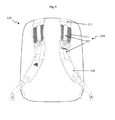
- Fig. 5 shows a variant 510 of the first embodiment of an insert for a carrying strap from fig. 1 .
- a backpack 530 with carrying straps 520 is illustrated.
- Backpack 530 is connected to the carrying strap 520 via connection section 517 and the insert 510, and the insert 510 comprises an elastic section 511 and a limitation section 512.
- elastic section 511 only comprises a single layer 511.
- the elastic section 511 extends over the whole width of carrying strap 520.
- the elastic section 511 extends only over a part of the width of carrying strap 520.
- the width of the elastic section 511 is approximately a quarter of the length of carrying strap 520
- a length of the limitation section 512 is approximately half of the length of carrying strap 520.
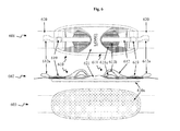
- Fig. 6 shows a top view 601, a side view 602 and a bottom view 603 of an insert 610 for carrying strap 620 which may be used, for example, as a shoulder strap for a carrying bag.
- Insert 610 is arranged between two ends of a carrying strap 620.
- Insert 610 comprises an elastic section 611 and a limitation section 612.
- the elastic section 611 comprises more than one layer, in particular two layers 611a, 611b.
- Limitation section 612 is connected to carrying strap 620 at both ends.
- limitation section 612 comprises at both ends a ladder lock buckle 619 for adjusting the length of limitation section 612 which limits the maximum elongation of elastic section 611 and therefore of insert 610.
- Limitation section 612 is formed as a band and comprises at both ends finger loops 612a for pulling.
- insert 610 comprises, similar to the embodiment of fig. 1 , a cover 621 comprising two openings which cover a part of the elastic section 611 and a part of the limitation section 612.
- Cover 621 is connected to carrying strap 620 so that sliding of elastic section 611 and limitation section 612 under the cover 621 is possible.
- Cover 621 therefore protects elastic section 611 and limitation section 612 and provides guidance during their movements.
- the openings of the insert 610 provide space for an extension of elastic section 611 and limitation section 612 when the length of the insert 610 is shortened due to a reduced load or a reduced vertical force.
- the lower side 610 of the insert 610 is formed as a closed surface, preferably a cushioned surface, so that elongations and contractions of the insert 610 do not chafe the body of the carrier of the carrying strap 620.
Landscapes
- Purses, Travelling Bags, Baskets, Or Suitcases (AREA)
- Portable Outdoor Equipment (AREA)
Abstract
Description
- The present invention relates to an insert for a carrying strap for carrying objects by persons.
- Carrying objects is made easier when they can be carried by hand using a handle or when they can be carried at the body using a carrying strap.
- A carrying strap has the advantage that the weight of the object is distributed over larger areas of the body. The use of two carrying straps, for example with a backpack, makes it even possible to distribute the weight symmetrically over the body. In this way, heavy loads can be carried. The
DE 10 2006 007 334 A1 describes a carrying system for a backpack with two shoulder straps. The length of the shoulder straps can be adjusted. - Carrying an object involves vertical movements and accelerations which results in additional vertical forces which act from the carried object on the body of the carrier of the object. These vertical forces increase when going up a staircase, on uneven ground or when going fast. This force is sensed as a hitch or a hit on the body.
- For cushioning such forces it is known to provide carrying straps with an elastic section which distributes the momentum carried over to the body caused by vertical accelerations over a longer time period and therefore results in a smaller force exerted on the body. For example, the
WO 03/007749 A1 - However, when carrying heavy loads and / or in case of strong vertical accelerations there is the risk that the elastic section is elongated too much or it is even over-elongated beyond the elasticity of the used material. In order to avoid this problem, it is known to limit the elongation of the elastic section, for example by an inelastic strap whose ends are stitched to the ends of the elastic section, as described in the
DE 299 10 127 . Similar limitations of the elongation of elastic sections are described in theUS 4,827,578 ,US 4,976,388 and theUS 2006/0163305 . In addition to a limitation of the elongation of an elastic section of a carrying strap theWO 94/16595 - Although such a limited cushioning makes it easier to carry loads, the comfort provided is limited to a specific range of the size of vertical forces. In contrast, the forces to be cushioned may vary to a great extent. A specific cushioning which is considered comfortable whilst walking may not be considered comfortable when running as a result of the substantially greater elongation of the elastic section when running, due to the stronger vertical forces.
- The present invention is therefore based on the problem to improve an elastic cushioning of a carrying strap so as to limit vertical forces arising from different movements.
- The present invention solves this problem with an insert for a carrying strap for carrying objects at the body according to claim 1. The insert comprises an essentially elastic section and a limitation section, wherein a length of the limitation section limits an elongation of the essentially elastic section. The length of the limitation section is adjustable.
- A carrying strap comprising such an insert may be used, for example, in a backpack and permits an adjustment of the cushioning to different requirements. For example, due to an additional load in the backpack, the vertical elongations of the essentially elastic section may become so large that a reduction of the elongations is desired. According to the invention this can be achieved by adjusting the length of the limitation section which limits an elongation of the essentially elastic section. Conversely, when the load is reduced the length of the limitation section may be increased.
- Similarly, during the transition from walking to running or during the transition from even to uneven ground, strong vertical movements and accelerations may arise which cause corresponding vertical forces.
- In all these cases, the vertical forces increase which results in a corresponding larger elongation of the elastic section. According to the invention this elongation can be adjusted by altering the length of the limitation section. The limitation section may even be shortened so that the elastic section cannot elongate any more. These possibilities improve the comfort due to an adaptation to different situations such as described above.
- In this application, a material is considered "essentially elastic" if it returns to its original state under common loads and forces except for negligible deviations. Accordingly, a material is considered "essentially inelastic" if common loads and forces do not cause a noticeable elongation of the material. Therefore, in the following the term "elastic" will be used instead of "essentially elastic", and the term "inelastic" will be used instead of "essentially inelastic".
- In a preferred embodiment the elastic section comprises more than one layer. This enables a variation of the elastic properties of the elastic section. Preferably, the layers of the elastic section each have different elasticities. It is further preferred that the layers of the elastic section each comprise different lengths. In this way, an insert may be realized in which the elasticity of the elastic section changes in proportion to the amount by which the elastic section elongates. For example, the force required for elongating the insert may increase stepwise with the elongation.
- In a preferred embodiment the limitation section is formed as a band. It is further preferred that the length of the limitation section is adjusted by means of a ladderlock buckle so that the limitation of the elongation of the insert can be adjusted at any time in a fast and simple manner.
- In a further embodiment the limitation section is formed as a cord. Preferably, a change of the length of the cord is greater than the resulting change of the length of the limitation section. The force required for an adjustment is therefore lowered, similar to a pulley. Further, this enables a more precise adjustment of the limitation of the elongation of the elastic section. Preferably, this is achieved by guiding the cord by inversion points.
- In a further embodiment the cord comprises a cord stop or cord lock or slide stop which can be used to adjust the length of the limitation section. Alternatively, the cord comprises a hook which can be used for a stepwise adjustment of the length of the limitation section.
- In one embodiment the limitation section comprises an essentially inelastic material. The elongation of the elastic section is therefore limited to the length of the limitation section.
- Alternatively, the limitation section comprises an essentially elastic material. In this case, the elongation of the elastic section is limited to the elongation of the limitation section. To this end, the elasticity of the limitation section should be equal to or smaller than the elasticity of the elastic section.
- The invention further comprises a carrying strap having an insert previously described and a backpack or carrying bag with at least one such carrying strap.
- A further embodiment is a backpack or carrying bag which comprises an insert, at least one carrying strap and a side section. The insert is arranged between the side section and an end of the at least one carrying strap. Adjusting the cushioning of this backpack or carrying bag therefore only requires an adjustment of a single insert and not of an insert for each carrying strap.
- Further embodiments of the insert for a carrying strap according to the invention are defined in further dependent claims.
- In the following aspects of the present invention are explained in more detail by referring to the accompanying figures. These figures show:
- Fig. 1:
- different views of a first embodiment of the invention;
- Fig. 2:
- different views of a second embodiment;
- Fig. 3:
- different views of a variant of the second embodiment;
- Fig. 4:
- a perspective view of a third embodiment;
- Fig. 5:
- a variant of the first embodiment from
fig. 1 ; and - Fig. 6:
- different views of a fourth embodiment
- In the following, embodiments and variations of the present invention are described in more detail with reference to an insert for a carrying strap of a backpack. In addition, the insert can be used with bags, carry-seats for babies or other carriers for carrying loads. A carrying strap with the insert can be used for carrying any object, for example for carrying sports devices such as a ski bag. As explained in the summary of the invention, in the following "elastic" is understood as "essentially elastic", and "inelastic" is understood as "essentially inelastic".
-
Fig. 1 shows a first embodiment of aninsert 110 of aleft carrying strap 120 in afront view 101 and aside view 102 as well as aback view 103 of abackpack 130 with the carryingstrap 120. Thebackpack 130 is connected to the carryingstrap 120 via aconnection section 117 and theinsert 110. Theconnection section 117 may comprise an inelastic or an elastic material or a combination of both. - The
insert 110 is arranged in theupper area 115 of the carryingstrap 120, i.e. at the end of the carryingstrap 120 which is connected to the upper side of thebackpack 130. One end of theinsert 110 is connected to theconnection section 117 of thebackpack 130, and the other end is connected to the carryingstrap 120 inarea 116 of carryingstrap 120. The connection of theinsert 110 and the carryingstrap 120 will be described in more detail in the following. Theinsert 110 together with theconnection section 117 therefore form the connection between the carryingstrap 120 and thebackpack 130. - The
insert 110 comprises an elastic section 111 which provides cushioning of vertical forces of thebackpack 130 on the carrier of the backpack, for example caused by vertical movements during walking. Such movements cause an elongation of theinsert 110 and therefore are not directly transferred to the carryingstrap 120 and the body, in particular the shoulders, of the carrier of thebackpack 130. Rather, the movements are delayed and distributed so that the force exerted on the body is reduced. This improves the wearing comfort. - The elastic section 111 comprises more than one layer, in particular two
layers layers connection section 117, and the other end of thelayers strap 120 in thearea 116. The position of thearea 116 is determined by a length of the elastic section 111. The length of the elastic section 111 may vary. In the embodiment offig. 1 , the length of the elastic section 111 is approximately one third of the length of the carryingstrap 120. In other examples, the length of the elastic section 111 may be approximately a half or a quarter of the length of the carryingstrap 120. - A material of the
lower layer 111a has a larger elasticity, i.e. a smaller resistance against elongation than a material of theupper layer 111b. As can be seen in theside view 102, thelower layer 111a is shorter than theupper layer 111b. Therefore, during an elongation of the elastic section 111 thelower layer 111a is elongated first, and subsequently theupper layer 111b is elongated. The resistance of the elastic section 111 against elongation is therefore increased in a stepwise manner, in proportion to the elongation of the elastic section 111. This principle can be transferred in analogy to more than two layers of the elastic section 111. The elasticity, width, thickness, and material oflayers - The
insert 110 further comprises alimitation section 112. As can be seen in theside view 102, thelimitation section 112 is longer than thelower layer 111a and theupper layer 111b of the elastic section 111. One end of thelimitation section 112 is connected to theconnection section 117, and the other end of thelimitation section 112 is connected to the carryingstrap 120 inarea 118. The effective length of thelimitation section 112 corresponds to the distance between the two points at which thelimitation section 112 is affixed to the carryingstrap 120 and theconnection section 117 respectively. In the embodiment offig. 1 ,area 118 is arranged approximately in the middle of the carryingstrap 120, so that length of thelimitation section 112 is approximately half of the length of the carrying strap. The length of thelimitation section 112 may vary and amounts to, for example, two thirds or one third of the length of the carryingstrap 120. - The
limitation section 112 comprises an inelastic material, and therefore the length of thelimitation section 112 limits the maximum elongation of the elastic section 111. Alternatively, the limitation section may comprise an elastic material the elasticity of which is smaller than the elasticities of thelayers elongated limitation section 112 limits the elongation of the elastic section 111. Thelimitation section 112 may comprise at one end finger loops for pulling at thelimitation section 112 which are not illustrated infig. 1 . Examples are thefinger loops 612a infig. 6 . - In the embodiment of
Fig. 1 the width of thelower layer 111a is approximately 5 cm, the width of theupper layer 111b is approximately 3 cm, and the width of thelimitation section 112 formed as a band is approximately 1,5 cm. These values may vary in other embodiments. - The
side view 102 shows the elastic section 111 in a relaxed state in which thelayers - A part of the elastic section 111 and a part of the
limitation section 112 are covered by acover 121 which is connected to the carryingstrap 120 so that it permits sliding of the elastic section 111 and thelimitation section 112 under thecover 121. Cover 121 therefore protects theelastic section 110 and thelimitation section 112 and provides guidance for these sections during their movements. - When using the
insert 110 in different situations, substantially differing forces may act on theinsert 110 which will cause correspondingly differing elongations. It may therefore be desirable to change the maximum elongation of theinsert 110 which is determined by the length of thelimitation section 112. This is enabled byladderlock buckle 119 which can be used to change the length of the limitation section.Ladderlock buckle 119 is arranged in the section oflimitation section 112 which is not covered bycover 121. Use of aladderlock buckle 119 and its arrangement at the carryingstrap 120 facilitates changing the maximum elongation of the elastic section 111 and thereby of theinsert 110 rapidly and at any time, for example during a transition from walking to running. - As can be recognized in
Fig. 1 , thelimitation section 112 can be shortened so that it is shorter than or equal to the length of thelower layer 111a. In this case, the elastic section 111 cannot elongate any more. In this position theinsert 110 therefore has no elasticity. -
Fig. 2 shows a second embodiment of aninsert 210 of aleft carrying strap 220 in afront view 201 and aside view 202 and aback view 203 of abackpack 230 with the carryingstrap 220. The carryingstrap 220 is connected to thebackpack 230 via theinsert 210 and aconnection section 217. In this embodiment, theconnection section 217 is substantially longer than theconnection section 117 inFig. 1 . Therefore, in contrast toFig. 1 , theinsert 210 is arranged in amiddle area 215 of the carryingstrap 220. Since theconnection section 217overlays carrying strap 220,connection section 217 glides on carryingstrap 220 during elongations of theinsert 210, rather than on a garment of the carrier of the backpack. This improves the comfort. During movements of theconnection section 217 with respect to carryingstrap 220, theconnection section 217 is guided byguidance 221 which is connected to the carryingstrap 220. -
Elastic section 211 ofinsert 210 comprises more than one layer, in particular three layers which are illustrated in theside view 202 inFig. 2 . In the embodiment ofFig. 2 these layers have essentially the same length and the same elasticity. Preferably,elastic section 211 has a width of approximately 5 cm and comprises an elastic material. One end ofelastic section 211 is connected to theconnection section 217, and the other end ofelastic section 211 is connected to the carryingstrap 220 in thearea 216.Elastic insert 210 is illustrated inFig. 2 in a relaxed state. -
Insert 210 further comprises alimitation section 212.Adjustment section 212 comprises acord 212a, preferably an inelastic cord.Cord 212a preferably has a diameter of about 3 mm. Alternatively, an elastic cord can be used whose elasticity is equal to or smaller than the elasticity of theelastic section 211. Two ends of thecord 212a are fixed to the borders of carryingstrap 220 inarea 216. They run further throughloops 219a, which are fixed inarea 218 toconnection section 217, and through asingle loop 219b, which is connected to carryingstrap 220 inarea 216. Beyondloop 219b cordslide lock 225. By pulling or releasingcord 212a usingslide lock 225 the maximum elongation of theinsert 210 can be continuously adjusted, and in this position the cord 225 a is fixed using theslide lock 225. Theslide lock 225 is fixed to the carryingstrap 220, for example by sewing. The length of thelimitation section 212 which limits the elongation of theinsert 210 is determined by the distance between the point at which thecord 212a is affixed to the carryingstrap 220 inarea 216 and the point where thecord 212a runs through theloops 219a, in a tensioned state of thecord 212a. The length of thelimitation section 212 can be adjusted usingcord 212a.Loops 219a act as turning points forcord 212a so thatlimitation section 212 becomes a "pulley". Namely, a reduction of the elongation ofelastic section 211 by distance S requires thatcord 212a is shortened by distance 2S. This halves the force which is needed for reducing the length ofcord 212a, against the weight of the backpack. Conversely, the weight of the backpack can be used for increasing the elongation ofinsert 210 when the backpack is carried, since the weight acts in the direction of a larger elongation ofelastic section 211. -
Fig. 3 illustrates a variant of the second embodiment ofFig. 2 . In contrast toFig. 2 , the two ends ofcord 312a oflimitation section 312 are connected toconnection section 217 inarea 318. They run further throughloops 319a, which are fixed to carryingstrap 320 inarea 316, and further through asingle loop 319b, which is connected toconnection section 217 inarea 318. Beyondloop 319b cordhook 325. Hook 325 can be hooked intoloops 326 which are fixed to carryingstrap 320 at different distances fromloop 319b. This permits a stepwise adjustment of the elongation ofinsert 310. The manner in which the length oflimitation section 312 is adjusted is analogous to that described in relation to the embodiment ofFig. 2 . -
Fig. 4 illustrates a third embodiment of aninsert 410 in a perspective view. In this embodiment, asingle insert 410 is arranged between aside section 430, in particular a back section, of a backpack and the ends of carryingstraps 420. -
Insert 410 comprises anelastic section 411 which extends substantially across the whole width ofback section 430.Limitation section 412 comprises acord 412a which runs alternating betweenloops Loops 419a are connected to carryingstraps 420, andloops 419b are connected toside section 430. Both ends ofcord 412a meet atslide lock 425 on one side ofinsert 410. By pulling or releasingcord 412a the maximum elongation ofinsert 410 can be reduced or increased. Releasingcord 412a can be supported by the weight of the backpack when the backpack is carried. This embodiment has the advantage that the cushioning for both carryingstraps 420 can be adjusted simultaneously usinginsert 410, instead of adjusting the carryingstraps 420 separately. - The length of
limitation section 412 which limits the elongation ofelastic section 411 is determined by the distance betweenloops 419a andloops 419b, in a situation whencord 412a is tensioned. - A limitation section could also be formed by a wire which runs in a manner similar to
cords - In the embodiments of
Fig. 2 to 4 ,cord limitation section cord limitation section elastic section -
Fig. 5 shows avariant 510 of the first embodiment of an insert for a carrying strap fromfig. 1 . Infig. 5 abackpack 530 with carryingstraps 520 is illustrated.Backpack 530 is connected to the carryingstrap 520 viaconnection section 517 and theinsert 510, and theinsert 510 comprises anelastic section 511 and alimitation section 512. In contrast tofig. 1 ,elastic section 511 only comprises asingle layer 511. Theelastic section 511 extends over the whole width of carryingstrap 520. In other embodiments theelastic section 511 extends only over a part of the width of carryingstrap 520. Infig. 5 the width of theelastic section 511 is approximately a quarter of the length of carryingstrap 520, and a length of thelimitation section 512 is approximately half of the length of carryingstrap 520. These lengths relations may vary in other embodiments. -
Fig. 6 shows atop view 601, aside view 602 and abottom view 603 of aninsert 610 for carryingstrap 620 which may be used, for example, as a shoulder strap for a carrying bag.Insert 610 is arranged between two ends of a carryingstrap 620.Insert 610 comprises anelastic section 611 and alimitation section 612. Theelastic section 611 comprises more than one layer, in particular twolayers -
Limitation section 612 is connected to carryingstrap 620 at both ends. In contrast tofig. 1 ,limitation section 612 comprises at both ends aladder lock buckle 619 for adjusting the length oflimitation section 612 which limits the maximum elongation ofelastic section 611 and therefore ofinsert 610.Limitation section 612 is formed as a band and comprises at both endsfinger loops 612a for pulling. - Further, insert 610 comprises, similar to the embodiment of
fig. 1 , acover 621 comprising two openings which cover a part of theelastic section 611 and a part of thelimitation section 612. Cover 621 is connected to carryingstrap 620 so that sliding ofelastic section 611 andlimitation section 612 under thecover 621 is possible. Cover 621 therefore protectselastic section 611 andlimitation section 612 and provides guidance during their movements. The openings of theinsert 610 provide space for an extension ofelastic section 611 andlimitation section 612 when the length of theinsert 610 is shortened due to a reduced load or a reduced vertical force. - The
lower side 610 of theinsert 610 is formed as a closed surface, preferably a cushioned surface, so that elongations and contractions of theinsert 610 do not chafe the body of the carrier of the carryingstrap 620.
Claims (15)
- Insert (110, 210, 310, 410, 510, 610) for a carrying strap (120, 220, 320, 420, 520, 620) for carrying objects (130), comprising:a. an essentially elastic section (111, 211, 311, 411, 511, 611);b. a limitation section (112, 212, 312, 412, 512, 612), wherein a length of the limitation section (112, 212, 312, 412, 512, 612) limits an elongation of the essentially elastic section (111,211,311, 411, 11, 611); characterized in thatc. the length of the limitation section (112, 212, 312, 412, 512, 612) is adjustable.
- Insert (110, 210, 310, 610) according to the preceding claim, wherein the essentially elastic section (111, 611) comprises more than one layer (111a, 111b; 611a, 611b).
- Insert (110, 210, 310, 610) according to the preceding claim, wherein the layers (111a, 111b; 611a, 611b) of the essentially elastic section (111, 611) each comprise different elasticities.
- Insert (110, 610) according to one of the claims 2 or 3, wherein the layers (111a, 111b; 611a, 6111b) of the essentially elastic section (111, 611) each comprise different lengths.
- Insert (110, 510, 610) according to one of the preceding claims, wherein the limitation section (112, 512, 612) is formed as an adjustable band.
- Insert (110, 510, 610) according to one of the preceding claims, wherein the limitation section (112, 512, 612) comprises a ladderlock buckle (119, 619) for adjusting the length of the limitation section (112, 612).
- Insert (210, 310, 410) according to one of the claims 1 to 4, wherein the limitation section (212, 312, 412) is formed as an adjustable cord (212a, 312a, 412a).
- Insert (210, 310, 410) according to claim 7, wherein the cord (212a, 312a, 412a) is guided by at least one inversion point (219a, 319a, 419a, 419b).
- Insert (210, 410) according to one of the claims 7 to 8, wherein the cord (212a, 412a) comprises a slide lock (225, 425) for adjusting the length of the limitation section (212, 412).
- Insert (110, 210, 310, 410, 510, 610) according to one of the preceding claims, wherein the limitation section (112, 212, 312, 412, 512, 612) comprises an essentially inelastic material.
- Insert (110, 210, 310, 410, 510, 610) according to one of the claims 1 to 9, wherein the limitation section (112, 212, 312, 412, 512, 612) comprises an essentially elastic material.
- Insert (110, 210, 310, 410, 510, 610) according to claim 11, wherein the essentially elastic material of the limitation section (112, 212, 312, 412, 512, 612) is less elastic than the essentially elastic material of the elastic section (111, 211, 311, 411, 511, 611).
- Carrying strap (120, 220, 320, 420, 520, 620) comprising an insert (110, 210, 310, 410, 510, 610) according to one of the claims 1 to 12.
- Backpack (130, 530) or carrying bag, comprising at least one carrying strap (120, 220, 320, 420, 520, 620) according to claim 13.
- Backpack (130) or carrying bag, comprising an insert (410) according to one of the claims 1 to 12, at least one carrying strap (420), and a side section (430), wherein the insert (410) is arranged between the side section (430) and an end of the at least one carrying strap (420).
Applications Claiming Priority (1)
| Application Number | Priority Date | Filing Date | Title |
|---|---|---|---|
| DE102010003481.9A DE102010003481B4 (en) | 2010-03-30 | 2010-03-30 | Insert for a carrying strap |
Publications (3)
| Publication Number | Publication Date |
|---|---|
| EP2371232A2 true EP2371232A2 (en) | 2011-10-05 |
| EP2371232A3 EP2371232A3 (en) | 2013-10-30 |
| EP2371232B1 EP2371232B1 (en) | 2019-06-12 |
Family
ID=44303538
Family Applications (1)
| Application Number | Title | Priority Date | Filing Date |
|---|---|---|---|
| EP11159962.7A Active EP2371232B1 (en) | 2010-03-30 | 2011-03-28 | Insert for a carrying strap |
Country Status (4)
| Country | Link |
|---|---|
| US (1) | US9192221B2 (en) |
| EP (1) | EP2371232B1 (en) |
| CN (1) | CN102204749B (en) |
| DE (1) | DE102010003481B4 (en) |
Cited By (5)
| Publication number | Priority date | Publication date | Assignee | Title |
|---|---|---|---|---|
| FR3048858A1 (en) * | 2016-03-16 | 2017-09-22 | Life Member | TRANSFERABLE BACKPACK IN A VENTRAL POSITION FOR SITTING WITHOUT A GENE ON A FOLDER SEAT OR ACCESSING THE CONTENT OF THE BAG OR SECURING IT IN PUBLIC TRANSPORT AND IN THE CROWD |
| US20190038007A1 (en) * | 2017-08-01 | 2019-02-07 | S&S Precision, Llc | Load bearing harness |
| EP3549483A1 (en) * | 2018-04-06 | 2019-10-09 | adidas AG | Carrying system |
| WO2020128388A1 (en) | 2018-12-20 | 2020-06-25 | Gravibag | Bag provided with a load distribution accessory |
| FR3096561A1 (en) | 2019-06-03 | 2020-12-04 | Gravibag | Carrying sling equipped with a conformation frame |
Families Citing this family (15)
| Publication number | Priority date | Publication date | Assignee | Title |
|---|---|---|---|---|
| CN102771998A (en) * | 2012-07-31 | 2012-11-14 | 苏州市伦琴工业设计有限公司 | Elastic backpack |
| US10390582B2 (en) * | 2014-12-05 | 2019-08-27 | Two Guys And A Hat Inc. | Protective headgear |
| US9901163B2 (en) * | 2015-07-22 | 2018-02-27 | Nike, Inc. | Cable-tensioning system strap |
| US9888761B2 (en) * | 2016-03-21 | 2018-02-13 | Peter Kao | Backpack with suspension arrangement |
| US10130161B2 (en) * | 2016-03-21 | 2018-11-20 | Ox Distribution Group | Backpack with suspension arrangement |
| US10236665B2 (en) * | 2016-11-14 | 2019-03-19 | Infratech Corporation | Insulated electrical switch cabinet cover |
| USD923940S1 (en) * | 2018-07-03 | 2021-07-06 | Porter Classic Inc. | Shoulder strap for bag |
| WO2020163585A1 (en) * | 2019-02-08 | 2020-08-13 | Lillebaby, Llc | Carrier with an adjustable base |
| USD930355S1 (en) * | 2019-03-22 | 2021-09-14 | Little Bug Creations, LLC | Baby carrier |
| USD889842S1 (en) * | 2019-06-05 | 2020-07-14 | Callaway Golf Company | Pair of bag straps |
| USD910309S1 (en) * | 2019-07-24 | 2021-02-16 | The Boppy Company, Llc | Component for baby carrier |
| US10806237B1 (en) * | 2019-09-06 | 2020-10-20 | Zarko Popovic | Backpack having detachable straps and adjustable in position on user |
| US11529895B2 (en) | 2020-03-31 | 2022-12-20 | Dorel Juvenile Group, Inc. | Extensible child restraint carry handle |
| CN219460549U (en) * | 2022-10-12 | 2023-08-04 | 深圳市恒炎创新科技有限公司 | Suspension module and knapsack with cushioning effect |
| WO2026072562A1 (en) * | 2024-09-24 | 2026-04-02 | Under Armour, Inc. | Backpack including suspension strap |
Citations (7)
| Publication number | Priority date | Publication date | Assignee | Title |
|---|---|---|---|---|
| US4827578A (en) | 1986-01-10 | 1989-05-09 | Heckerman William L | Harness |
| US4976388A (en) | 1990-01-30 | 1990-12-11 | Coontz James D | Shoulder strap assembly having limited stretchability |
| WO1994016595A1 (en) | 1993-01-22 | 1994-08-04 | American Unimax | Shoulder strap assembly |
| DE29910127U1 (en) | 1998-07-17 | 1999-09-09 | Skis Rossignol S.A., Voiron | Back pocket |
| WO2003007749A1 (en) | 2001-07-18 | 2003-01-30 | JACK WOLFSKIN Ausrüstung für Draussen GmbH & Co. KGaA | Strap and container provided with such a strap |
| US20060163305A1 (en) | 2005-01-27 | 2006-07-27 | Agron, Inc. | Backpack frame |
| DE102006007334A1 (en) | 2006-02-16 | 2007-08-30 | Tatonka Gmbh | Carrying system for backpacks |
Family Cites Families (16)
| Publication number | Priority date | Publication date | Assignee | Title |
|---|---|---|---|---|
| US1493684A (en) * | 1921-03-14 | 1924-05-13 | Andrew J Linder | Flexible fastener for belts |
| US1734371A (en) * | 1925-11-18 | 1929-11-05 | Steellastic Company | Supporter |
| GB479442A (en) * | 1936-08-05 | 1938-02-07 | John Mcginn | Improvements relating to shoulder carrying straps for bags |
| US5143266A (en) * | 1986-01-10 | 1992-09-01 | Butler Creek Corporation | Harness |
| US5695102A (en) * | 1995-04-28 | 1997-12-09 | William R. Heckerman | Elastic shoulder strap |
| US5890640A (en) * | 1996-08-14 | 1999-04-06 | K-2 Corporation | Internal frame pack with load-responsive spring rods |
| US20050258205A1 (en) * | 2004-05-21 | 2005-11-24 | Michaels Of Oregon Co. | Shock-absorbing carrying strap |
| US7537510B2 (en) * | 2004-07-21 | 2009-05-26 | Hbi Branded Apparel Enterprises, Llc | Garment having dig free strap |
| US7458135B2 (en) * | 2005-11-21 | 2008-12-02 | Castle Mountain Enterprises, Llc | Tether |
| US20070261213A1 (en) * | 2006-05-10 | 2007-11-15 | Nolan Barara K | Detachable shock absorber accessory for shoulder strap |
| US20080217371A1 (en) * | 2006-10-18 | 2008-09-11 | Best Made Designs, L.L.C. | Universal firearm sling |
| US8132699B2 (en) * | 2006-12-19 | 2012-03-13 | Three Point Ventures Llc | Shoulder strap for bag |
| DE602007013862D1 (en) * | 2007-01-03 | 2011-05-26 | Mrm Holdings Ltd | Pocket with reinforced adjustable shoulder strap |
| US8366081B2 (en) * | 2007-04-26 | 2013-02-05 | Nike, Inc. | System for moderating forces |
| US20090294500A1 (en) * | 2008-05-30 | 2009-12-03 | Rooster Products International, Inc. | Load suspension system |
| US8789734B2 (en) * | 2009-05-18 | 2014-07-29 | Nike, Inc. | Carry bags with tensile strand reinforcing elements |
-
2010
- 2010-03-30 DE DE102010003481.9A patent/DE102010003481B4/en active Active
-
2011
- 2011-03-24 CN CN201110071763.1A patent/CN102204749B/en not_active Expired - Fee Related
- 2011-03-28 EP EP11159962.7A patent/EP2371232B1/en active Active
- 2011-03-30 US US13/076,093 patent/US9192221B2/en active Active
Patent Citations (7)
| Publication number | Priority date | Publication date | Assignee | Title |
|---|---|---|---|---|
| US4827578A (en) | 1986-01-10 | 1989-05-09 | Heckerman William L | Harness |
| US4976388A (en) | 1990-01-30 | 1990-12-11 | Coontz James D | Shoulder strap assembly having limited stretchability |
| WO1994016595A1 (en) | 1993-01-22 | 1994-08-04 | American Unimax | Shoulder strap assembly |
| DE29910127U1 (en) | 1998-07-17 | 1999-09-09 | Skis Rossignol S.A., Voiron | Back pocket |
| WO2003007749A1 (en) | 2001-07-18 | 2003-01-30 | JACK WOLFSKIN Ausrüstung für Draussen GmbH & Co. KGaA | Strap and container provided with such a strap |
| US20060163305A1 (en) | 2005-01-27 | 2006-07-27 | Agron, Inc. | Backpack frame |
| DE102006007334A1 (en) | 2006-02-16 | 2007-08-30 | Tatonka Gmbh | Carrying system for backpacks |
Cited By (11)
| Publication number | Priority date | Publication date | Assignee | Title |
|---|---|---|---|---|
| FR3048858A1 (en) * | 2016-03-16 | 2017-09-22 | Life Member | TRANSFERABLE BACKPACK IN A VENTRAL POSITION FOR SITTING WITHOUT A GENE ON A FOLDER SEAT OR ACCESSING THE CONTENT OF THE BAG OR SECURING IT IN PUBLIC TRANSPORT AND IN THE CROWD |
| US20190038007A1 (en) * | 2017-08-01 | 2019-02-07 | S&S Precision, Llc | Load bearing harness |
| US10605574B2 (en) * | 2017-08-01 | 2020-03-31 | S&S Precision, Llc | Load bearing harness |
| EP3549483A1 (en) * | 2018-04-06 | 2019-10-09 | adidas AG | Carrying system |
| DE102018205186A1 (en) | 2018-04-06 | 2019-10-10 | Adidas Ag | carrying system |
| CN110338552A (en) * | 2018-04-06 | 2019-10-18 | 阿迪达斯股份公司 | Load System |
| JP2019188125A (en) * | 2018-04-06 | 2019-10-31 | アディダス アーゲー | Transport system |
| WO2020128388A1 (en) | 2018-12-20 | 2020-06-25 | Gravibag | Bag provided with a load distribution accessory |
| FR3090284A1 (en) | 2018-12-20 | 2020-06-26 | Gravibag | Bag equipped with a load distribution accessory |
| FR3096561A1 (en) | 2019-06-03 | 2020-12-04 | Gravibag | Carrying sling equipped with a conformation frame |
| WO2020245530A1 (en) | 2019-06-03 | 2020-12-10 | Gravibag | Carrying strap equipped with a shaping reinforcement |
Also Published As
| Publication number | Publication date |
|---|---|
| US9192221B2 (en) | 2015-11-24 |
| EP2371232A3 (en) | 2013-10-30 |
| DE102010003481A1 (en) | 2011-10-06 |
| US20120012628A1 (en) | 2012-01-19 |
| DE102010003481B4 (en) | 2016-10-06 |
| CN102204749A (en) | 2011-10-05 |
| CN102204749B (en) | 2015-06-24 |
| EP2371232B1 (en) | 2019-06-12 |
Similar Documents
| Publication | Publication Date | Title |
|---|---|---|
| EP2371232A2 (en) | Insert for a carrying strap | |
| EP2422642B1 (en) | Bag with self-adjusting straps | |
| US10076177B2 (en) | Compression system for backpack | |
| US7232048B2 (en) | Device for carrying a load on one's back and for adjusting the position of said load | |
| US6375053B1 (en) | Knapsack supported on the two shoulders by a pair of shoulder straps | |
| US20120048900A1 (en) | Anatomically adaptive and ergonomic load distribution strap | |
| EP3549483B1 (en) | Carrying system | |
| EP3338593B1 (en) | Backpack | |
| US20130206805A1 (en) | Variable suspension system for backpacks | |
| KR102518114B1 (en) | cinch pack | |
| US20210100340A1 (en) | Backpack having multiple connecting sites for shoulder straps | |
| US10617194B2 (en) | Load adjustment system for backpacks | |
| US8807405B2 (en) | Self adjusting contoured strap device and method | |
| US20120248161A1 (en) | Pad for shoulder strap | |
| US20240335686A1 (en) | Adjustable lineman safety belt | |
| WO2011163645A2 (en) | Sports training belt | |
| US7100809B2 (en) | Carrying bag | |
| KR101431799B1 (en) | Backpack with adaptive custom waist belt | |
| US9848687B2 (en) | Adjustable strap height mechanism | |
| US20140263498A1 (en) | Backpack carrier strap system | |
| KR20110124459A (en) | Backpack which can adjust position of rucksack | |
| CN102232692A (en) | Non-skid band of backpack | |
| EP4631390A1 (en) | Container for the transport of objects, such as a backpack, equipped with an apparatus for adjusting the shoulder belts or straps | |
| KR102593365B1 (en) | Adjustable shoulder strap | |
| CN220756827U (en) | Burden-reducing schoolbag |
Legal Events
| Date | Code | Title | Description |
|---|---|---|---|
| PUAI | Public reference made under article 153(3) epc to a published international application that has entered the european phase |
Free format text: ORIGINAL CODE: 0009012 |
|
| AK | Designated contracting states |
Kind code of ref document: A2 Designated state(s): AL AT BE BG CH CY CZ DE DK EE ES FI FR GB GR HR HU IE IS IT LI LT LU LV MC MK MT NL NO PL PT RO RS SE SI SK SM TR |
|
| AX | Request for extension of the european patent |
Extension state: BA ME |
|
| PUAL | Search report despatched |
Free format text: ORIGINAL CODE: 0009013 |
|
| AK | Designated contracting states |
Kind code of ref document: A3 Designated state(s): AL AT BE BG CH CY CZ DE DK EE ES FI FR GB GR HR HU IE IS IT LI LT LU LV MC MK MT NL NO PL PT RO RS SE SI SK SM TR |
|
| AX | Request for extension of the european patent |
Extension state: BA ME |
|
| RIC1 | Information provided on ipc code assigned before grant |
Ipc: A45F 3/04 20060101ALI20130924BHEP Ipc: A45C 13/30 20060101AFI20130924BHEP |
|
| 17P | Request for examination filed |
Effective date: 20140415 |
|
| RBV | Designated contracting states (corrected) |
Designated state(s): AL AT BE BG CH CY CZ DE DK EE ES FI FR GB GR HR HU IE IS IT LI LT LU LV MC MK MT NL NO PL PT RO RS SE SI SK SM TR |
|
| STAA | Information on the status of an ep patent application or granted ep patent |
Free format text: STATUS: EXAMINATION IS IN PROGRESS |
|
| 17Q | First examination report despatched |
Effective date: 20180904 |
|
| GRAP | Despatch of communication of intention to grant a patent |
Free format text: ORIGINAL CODE: EPIDOSNIGR1 |
|
| STAA | Information on the status of an ep patent application or granted ep patent |
Free format text: STATUS: GRANT OF PATENT IS INTENDED |
|
| INTG | Intention to grant announced |
Effective date: 20181219 |
|
| GRAS | Grant fee paid |
Free format text: ORIGINAL CODE: EPIDOSNIGR3 |
|
| GRAA | (expected) grant |
Free format text: ORIGINAL CODE: 0009210 |
|
| STAA | Information on the status of an ep patent application or granted ep patent |
Free format text: STATUS: THE PATENT HAS BEEN GRANTED |
|
| AK | Designated contracting states |
Kind code of ref document: B1 Designated state(s): AL AT BE BG CH CY CZ DE DK EE ES FI FR GB GR HR HU IE IS IT LI LT LU LV MC MK MT NL NO PL PT RO RS SE SI SK SM TR |
|
| REG | Reference to a national code |
Ref country code: GB Ref legal event code: FG4D |
|
| REG | Reference to a national code |
Ref country code: CH Ref legal event code: EP |
|
| REG | Reference to a national code |
Ref country code: AT Ref legal event code: REF Ref document number: 1141420 Country of ref document: AT Kind code of ref document: T Effective date: 20190615 |
|
| REG | Reference to a national code |
Ref country code: DE Ref legal event code: R096 Ref document number: 602011059564 Country of ref document: DE |
|
| REG | Reference to a national code |
Ref country code: IE Ref legal event code: FG4D |
|
| REG | Reference to a national code |
Ref country code: NL Ref legal event code: MP Effective date: 20190612 |
|
| REG | Reference to a national code |
Ref country code: LT Ref legal event code: MG4D |
|
| PG25 | Lapsed in a contracting state [announced via postgrant information from national office to epo] |
Ref country code: LT Free format text: LAPSE BECAUSE OF FAILURE TO SUBMIT A TRANSLATION OF THE DESCRIPTION OR TO PAY THE FEE WITHIN THE PRESCRIBED TIME-LIMIT Effective date: 20190612 Ref country code: HR Free format text: LAPSE BECAUSE OF FAILURE TO SUBMIT A TRANSLATION OF THE DESCRIPTION OR TO PAY THE FEE WITHIN THE PRESCRIBED TIME-LIMIT Effective date: 20190612 Ref country code: SE Free format text: LAPSE BECAUSE OF FAILURE TO SUBMIT A TRANSLATION OF THE DESCRIPTION OR TO PAY THE FEE WITHIN THE PRESCRIBED TIME-LIMIT Effective date: 20190612 Ref country code: NO Free format text: LAPSE BECAUSE OF FAILURE TO SUBMIT A TRANSLATION OF THE DESCRIPTION OR TO PAY THE FEE WITHIN THE PRESCRIBED TIME-LIMIT Effective date: 20190912 Ref country code: ES Free format text: LAPSE BECAUSE OF FAILURE TO SUBMIT A TRANSLATION OF THE DESCRIPTION OR TO PAY THE FEE WITHIN THE PRESCRIBED TIME-LIMIT Effective date: 20190612 Ref country code: AL Free format text: LAPSE BECAUSE OF FAILURE TO SUBMIT A TRANSLATION OF THE DESCRIPTION OR TO PAY THE FEE WITHIN THE PRESCRIBED TIME-LIMIT Effective date: 20190612 Ref country code: FI Free format text: LAPSE BECAUSE OF FAILURE TO SUBMIT A TRANSLATION OF THE DESCRIPTION OR TO PAY THE FEE WITHIN THE PRESCRIBED TIME-LIMIT Effective date: 20190612 |
|
| PG25 | Lapsed in a contracting state [announced via postgrant information from national office to epo] |
Ref country code: BG Free format text: LAPSE BECAUSE OF FAILURE TO SUBMIT A TRANSLATION OF THE DESCRIPTION OR TO PAY THE FEE WITHIN THE PRESCRIBED TIME-LIMIT Effective date: 20190912 Ref country code: GR Free format text: LAPSE BECAUSE OF FAILURE TO SUBMIT A TRANSLATION OF THE DESCRIPTION OR TO PAY THE FEE WITHIN THE PRESCRIBED TIME-LIMIT Effective date: 20190913 Ref country code: LV Free format text: LAPSE BECAUSE OF FAILURE TO SUBMIT A TRANSLATION OF THE DESCRIPTION OR TO PAY THE FEE WITHIN THE PRESCRIBED TIME-LIMIT Effective date: 20190612 Ref country code: RS Free format text: LAPSE BECAUSE OF FAILURE TO SUBMIT A TRANSLATION OF THE DESCRIPTION OR TO PAY THE FEE WITHIN THE PRESCRIBED TIME-LIMIT Effective date: 20190612 |
|
| REG | Reference to a national code |
Ref country code: AT Ref legal event code: MK05 Ref document number: 1141420 Country of ref document: AT Kind code of ref document: T Effective date: 20190612 |
|
| PG25 | Lapsed in a contracting state [announced via postgrant information from national office to epo] |
Ref country code: SK Free format text: LAPSE BECAUSE OF FAILURE TO SUBMIT A TRANSLATION OF THE DESCRIPTION OR TO PAY THE FEE WITHIN THE PRESCRIBED TIME-LIMIT Effective date: 20190612 Ref country code: PT Free format text: LAPSE BECAUSE OF FAILURE TO SUBMIT A TRANSLATION OF THE DESCRIPTION OR TO PAY THE FEE WITHIN THE PRESCRIBED TIME-LIMIT Effective date: 20191014 Ref country code: AT Free format text: LAPSE BECAUSE OF FAILURE TO SUBMIT A TRANSLATION OF THE DESCRIPTION OR TO PAY THE FEE WITHIN THE PRESCRIBED TIME-LIMIT Effective date: 20190612 Ref country code: CZ Free format text: LAPSE BECAUSE OF FAILURE TO SUBMIT A TRANSLATION OF THE DESCRIPTION OR TO PAY THE FEE WITHIN THE PRESCRIBED TIME-LIMIT Effective date: 20190612 Ref country code: NL Free format text: LAPSE BECAUSE OF FAILURE TO SUBMIT A TRANSLATION OF THE DESCRIPTION OR TO PAY THE FEE WITHIN THE PRESCRIBED TIME-LIMIT Effective date: 20190612 Ref country code: RO Free format text: LAPSE BECAUSE OF FAILURE TO SUBMIT A TRANSLATION OF THE DESCRIPTION OR TO PAY THE FEE WITHIN THE PRESCRIBED TIME-LIMIT Effective date: 20190612 Ref country code: EE Free format text: LAPSE BECAUSE OF FAILURE TO SUBMIT A TRANSLATION OF THE DESCRIPTION OR TO PAY THE FEE WITHIN THE PRESCRIBED TIME-LIMIT Effective date: 20190612 |
|
| PG25 | Lapsed in a contracting state [announced via postgrant information from national office to epo] |
Ref country code: SM Free format text: LAPSE BECAUSE OF FAILURE TO SUBMIT A TRANSLATION OF THE DESCRIPTION OR TO PAY THE FEE WITHIN THE PRESCRIBED TIME-LIMIT Effective date: 20190612 Ref country code: IT Free format text: LAPSE BECAUSE OF FAILURE TO SUBMIT A TRANSLATION OF THE DESCRIPTION OR TO PAY THE FEE WITHIN THE PRESCRIBED TIME-LIMIT Effective date: 20190612 Ref country code: IS Free format text: LAPSE BECAUSE OF FAILURE TO SUBMIT A TRANSLATION OF THE DESCRIPTION OR TO PAY THE FEE WITHIN THE PRESCRIBED TIME-LIMIT Effective date: 20191012 |
|
| REG | Reference to a national code |
Ref country code: DE Ref legal event code: R097 Ref document number: 602011059564 Country of ref document: DE |
|
| PG25 | Lapsed in a contracting state [announced via postgrant information from national office to epo] |
Ref country code: TR Free format text: LAPSE BECAUSE OF FAILURE TO SUBMIT A TRANSLATION OF THE DESCRIPTION OR TO PAY THE FEE WITHIN THE PRESCRIBED TIME-LIMIT Effective date: 20190612 |
|
| PLBE | No opposition filed within time limit |
Free format text: ORIGINAL CODE: 0009261 |
|
| STAA | Information on the status of an ep patent application or granted ep patent |
Free format text: STATUS: NO OPPOSITION FILED WITHIN TIME LIMIT |
|
| PG25 | Lapsed in a contracting state [announced via postgrant information from national office to epo] |
Ref country code: DK Free format text: LAPSE BECAUSE OF FAILURE TO SUBMIT A TRANSLATION OF THE DESCRIPTION OR TO PAY THE FEE WITHIN THE PRESCRIBED TIME-LIMIT Effective date: 20190612 Ref country code: PL Free format text: LAPSE BECAUSE OF FAILURE TO SUBMIT A TRANSLATION OF THE DESCRIPTION OR TO PAY THE FEE WITHIN THE PRESCRIBED TIME-LIMIT Effective date: 20190612 |
|
| 26N | No opposition filed |
Effective date: 20200313 |
|
| PG25 | Lapsed in a contracting state [announced via postgrant information from national office to epo] |
Ref country code: IS Free format text: LAPSE BECAUSE OF FAILURE TO SUBMIT A TRANSLATION OF THE DESCRIPTION OR TO PAY THE FEE WITHIN THE PRESCRIBED TIME-LIMIT Effective date: 20200224 Ref country code: SI Free format text: LAPSE BECAUSE OF FAILURE TO SUBMIT A TRANSLATION OF THE DESCRIPTION OR TO PAY THE FEE WITHIN THE PRESCRIBED TIME-LIMIT Effective date: 20190612 |
|
| PG2D | Information on lapse in contracting state deleted |
Ref country code: IS |
|
| PG25 | Lapsed in a contracting state [announced via postgrant information from national office to epo] |
Ref country code: IS Free format text: LAPSE BECAUSE OF FAILURE TO SUBMIT A TRANSLATION OF THE DESCRIPTION OR TO PAY THE FEE WITHIN THE PRESCRIBED TIME-LIMIT Effective date: 20191112 |
|
| PG25 | Lapsed in a contracting state [announced via postgrant information from national office to epo] |
Ref country code: MC Free format text: LAPSE BECAUSE OF FAILURE TO SUBMIT A TRANSLATION OF THE DESCRIPTION OR TO PAY THE FEE WITHIN THE PRESCRIBED TIME-LIMIT Effective date: 20190612 |
|
| REG | Reference to a national code |
Ref country code: CH Ref legal event code: PL |
|
| REG | Reference to a national code |
Ref country code: BE Ref legal event code: MM Effective date: 20200331 |
|
| PG25 | Lapsed in a contracting state [announced via postgrant information from national office to epo] |
Ref country code: LU Free format text: LAPSE BECAUSE OF NON-PAYMENT OF DUE FEES Effective date: 20200328 |
|
| PG25 | Lapsed in a contracting state [announced via postgrant information from national office to epo] |
Ref country code: FR Free format text: LAPSE BECAUSE OF NON-PAYMENT OF DUE FEES Effective date: 20200331 Ref country code: IE Free format text: LAPSE BECAUSE OF NON-PAYMENT OF DUE FEES Effective date: 20200328 Ref country code: LI Free format text: LAPSE BECAUSE OF NON-PAYMENT OF DUE FEES Effective date: 20200331 Ref country code: CH Free format text: LAPSE BECAUSE OF NON-PAYMENT OF DUE FEES Effective date: 20200331 |
|
| PG25 | Lapsed in a contracting state [announced via postgrant information from national office to epo] |
Ref country code: BE Free format text: LAPSE BECAUSE OF NON-PAYMENT OF DUE FEES Effective date: 20200331 |
|
| PGFP | Annual fee paid to national office [announced via postgrant information from national office to epo] |
Ref country code: GB Payment date: 20210219 Year of fee payment: 11 |
|
| PG25 | Lapsed in a contracting state [announced via postgrant information from national office to epo] |
Ref country code: MT Free format text: LAPSE BECAUSE OF FAILURE TO SUBMIT A TRANSLATION OF THE DESCRIPTION OR TO PAY THE FEE WITHIN THE PRESCRIBED TIME-LIMIT Effective date: 20190612 Ref country code: CY Free format text: LAPSE BECAUSE OF FAILURE TO SUBMIT A TRANSLATION OF THE DESCRIPTION OR TO PAY THE FEE WITHIN THE PRESCRIBED TIME-LIMIT Effective date: 20190612 |
|
| PG25 | Lapsed in a contracting state [announced via postgrant information from national office to epo] |
Ref country code: MK Free format text: LAPSE BECAUSE OF FAILURE TO SUBMIT A TRANSLATION OF THE DESCRIPTION OR TO PAY THE FEE WITHIN THE PRESCRIBED TIME-LIMIT Effective date: 20190612 |
|
| GBPC | Gb: european patent ceased through non-payment of renewal fee |
Effective date: 20220328 |
|
| PG25 | Lapsed in a contracting state [announced via postgrant information from national office to epo] |
Ref country code: GB Free format text: LAPSE BECAUSE OF NON-PAYMENT OF DUE FEES Effective date: 20220328 |
|
| PGFP | Annual fee paid to national office [announced via postgrant information from national office to epo] |
Ref country code: DE Payment date: 20260219 Year of fee payment: 16 |