EP2371168B1 - Method and base station for power saving - Google Patents
Method and base station for power saving Download PDFInfo
- Publication number
- EP2371168B1 EP2371168B1 EP08876333.9A EP08876333A EP2371168B1 EP 2371168 B1 EP2371168 B1 EP 2371168B1 EP 08876333 A EP08876333 A EP 08876333A EP 2371168 B1 EP2371168 B1 EP 2371168B1
- Authority
- EP
- European Patent Office
- Prior art keywords
- cell
- base station
- power mode
- communication device
- load
- Prior art date
- Legal status (The legal status is an assumption and is not a legal conclusion. Google has not performed a legal analysis and makes no representation as to the accuracy of the status listed.)
- Not-in-force
Links
- 238000000034 method Methods 0.000 title claims abstract description 26
- 238000004891 communication Methods 0.000 claims abstract description 94
- 230000000694 effects Effects 0.000 claims abstract description 64
- 230000011664 signaling Effects 0.000 claims description 19
- 238000005516 engineering process Methods 0.000 claims description 9
- 238000004458 analytical method Methods 0.000 description 7
- 230000001960 triggered effect Effects 0.000 description 6
- 230000004044 response Effects 0.000 description 3
- 230000006870 function Effects 0.000 description 2
- 238000012545 processing Methods 0.000 description 2
- 230000003044 adaptive effect Effects 0.000 description 1
- 230000001413 cellular effect Effects 0.000 description 1
- 230000001419 dependent effect Effects 0.000 description 1
- 230000005611 electricity Effects 0.000 description 1
- 230000007774 longterm Effects 0.000 description 1
- 238000012423 maintenance Methods 0.000 description 1
- 238000012986 modification Methods 0.000 description 1
- 230000004048 modification Effects 0.000 description 1
- 238000005457 optimization Methods 0.000 description 1
Images


Classifications
-
- H—ELECTRICITY
- H04—ELECTRIC COMMUNICATION TECHNIQUE
- H04W—WIRELESS COMMUNICATION NETWORKS
- H04W52/00—Power management, e.g. Transmission Power Control [TPC] or power classes
- H04W52/02—Power saving arrangements
- H04W52/0209—Power saving arrangements in terminal devices
- H04W52/0225—Power saving arrangements in terminal devices using monitoring of external events, e.g. the presence of a signal
- H04W52/0229—Power saving arrangements in terminal devices using monitoring of external events, e.g. the presence of a signal where the received signal is a wanted signal
- H04W52/0232—Power saving arrangements in terminal devices using monitoring of external events, e.g. the presence of a signal where the received signal is a wanted signal according to average transmission signal activity
-
- H—ELECTRICITY
- H04—ELECTRIC COMMUNICATION TECHNIQUE
- H04W—WIRELESS COMMUNICATION NETWORKS
- H04W52/00—Power management, e.g. Transmission Power Control [TPC] or power classes
- H04W52/02—Power saving arrangements
- H04W52/0203—Power saving arrangements in the radio access network or backbone network of wireless communication networks
- H04W52/0206—Power saving arrangements in the radio access network or backbone network of wireless communication networks in access points, e.g. base stations
-
- H—ELECTRICITY
- H04—ELECTRIC COMMUNICATION TECHNIQUE
- H04W—WIRELESS COMMUNICATION NETWORKS
- H04W88/00—Devices specially adapted for wireless communication networks, e.g. terminals, base stations or access point devices
- H04W88/08—Access point devices
-
- Y—GENERAL TAGGING OF NEW TECHNOLOGICAL DEVELOPMENTS; GENERAL TAGGING OF CROSS-SECTIONAL TECHNOLOGIES SPANNING OVER SEVERAL SECTIONS OF THE IPC; TECHNICAL SUBJECTS COVERED BY FORMER USPC CROSS-REFERENCE ART COLLECTIONS [XRACs] AND DIGESTS
- Y02—TECHNOLOGIES OR APPLICATIONS FOR MITIGATION OR ADAPTATION AGAINST CLIMATE CHANGE
- Y02D—CLIMATE CHANGE MITIGATION TECHNOLOGIES IN INFORMATION AND COMMUNICATION TECHNOLOGIES [ICT], I.E. INFORMATION AND COMMUNICATION TECHNOLOGIES AIMING AT THE REDUCTION OF THEIR OWN ENERGY USE
- Y02D30/00—Reducing energy consumption in communication networks
- Y02D30/70—Reducing energy consumption in communication networks in wireless communication networks
Definitions
- Embodiments herein refer to a base station and a method in a communications network, in particular, relating to power saving within the communications network.
- Saving electric power in a base station can be done in different ways, such as: making power saving optimizations in the base station implementation, introducing newer more power efficient components, or introducing functionality where the base station partly powers off during low traffic periods.
- Patent document WO 02/07464 A1, 24.01.2002 discloses a method for adaptive power management for a node of a cellular telecommunications network.
- Embodiments are disclosed herein to provide an efficient and reliable manner to save power in a base station.
- a method in a base station for determining a power mode for the base station to enter is disclosed.
- the base station determines cell load indicating user equipment activity within a first local cell of the base station and receives cell load information from a communication device comprising an indication of user equipment activity within a second cell associated to the communication device.
- the base station determines the power mode for the base station to enter based on the received cell load information and the determined load in the first local cell.
- a base station In order to perform the method a base station is provided.
- the base station comprises a control unit arranged to determine cell load in a first local cell associated to the base station indicating user equipment activity within the first local cell.
- the base station comprises a network interface arranged to receive cell load information from a communication device comprising an indication of user equipment activity within a second cell associated to the communication device.
- the control unit is further arranged to determine a power mode for the base station to enter, the base station serving the first local cell, based on the received cell load information and the determined load in the first local cell.
- Examples herein disclose ways to make more intelligent decisions regarding the power mode in a base station resulting in a more efficient and reliable manner.
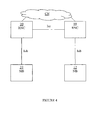
- FIG 1 a schematic overview of a communications network is disclosed.
- a first communication device 10, for example, a base station or the like, comprises a power saving function.
- a second communication device 20, for example, a base station, a controller node, and/or the like, comprises information of User Equipment (UE) 100 activity within a cell B.
- the second communication device 20 transmits cell load information indicating UE activity within the cell B over an Internode connection IC to the first communication device 10. This may be sent as a response to a request from a first communication device 10, but may also be information previously 'subscribed' to, i.e. data is sent by neighboring cells without needing a specific request all the time. It could also be information that is sent triggered when a specific event occurs.
- the first communication device 10 receives the cell load information indicating UE activity in the cell B over the IC and analyses the information separately and/or in conjunction with local cell load information indicating UE activity in a local cell A controlled/served by the first communication device. Based on the analysis the first communication device 10 takes a power mode decision and sets itself up into the determined power mode. Hence, the first communication device determines what power mode to enter based on local and neighboring cell information. It should here be understood that the determined power mode may be sent to a base station comprising the cell A, if the decision is taken in a node controlling the base station of cell A.
- FIG 2 a schematic overview of a combined method and signaling scheme in an EPS network is shown.
- LTE Long Term Evolution
- a base station enhanced Node B (eNB) 10
- eNB enhanced Node B
- eNB enhanced Node B
- the base station detects that some of its hardware is not needed (due to for example low traffic periods) it can be switched off in order to save power.
- neighbor base stations eNBs 10, 20 are connected by means of an X2 interface. This means that neighbor base stations eNB 10, eNB 20 may exchange signaling information over this connection.
- the eNB 10 determines the cell load of a local cell within the eNB 10 and requests the cell load of a neighbor cell, adjacent the local cell, of the eNB 20.
- the cell load comprises an indication of UE activity within the cell.
- step A2 the eNB 20 receives the request and determines the UE activity within the requested cell and transmits the cell load comprising an indication of the determined UE activity with the cell.
- the signaling protocol X2 in the illustrated example, comprises information about current UE activity in a cell of the neighbor eNB 20. This means that the eNB 20 may inform its neighbor eNBs about current UE activity within a cell of the eNB 20. Examples of information to be conveyed:
- the reports may be sent periodically or on demand from the eNB 10/an Operation and Maintenance O&M node. Rules could be defined so that reports are sent under certain conditions , e.g. a report should always be sent when then number of active users goes from 0 to >0, and/or a report should be sent when number of active user goes down to 0.
- step A3 the eNB 10 receives the report and analyses the cell load indicating the UE activity of the neighbor cell separately or together with the determined local cell load indicating the UE activity of the local cell.
- step A4 the eNB 10 determines a power mode for the eNB 10 to enter based on the analysis and enters the determined power mode.
- the receiving base station eNB 10 could take a decision on how to perform power saving. The exact algorithm to do so may be manufacturer dependent, but examples could be:
- a change in power mode of the base station also may affect how auxiliary site equipment, such as air-condition, battery back-up system etc, is used. That is, the auxiliary site equipment can be controlled on the basis of the power consumption of the base station and also enter different power modes based on the power mode of the base station.
- auxiliary site equipment such as air-condition, battery back-up system etc
- More advanced schemes may be envisioned, for example, by also weighting in handover statistics or information about the positions of the active UEs. Such information could be used to estimate the probability that the cell in question will need to take traffic in the close future. For example: if there is activity in a neighbor cell to which a cell frequently receives incoming handovers, it is likely that some UEs will be handed over in the future if there has been reported about activity in that neighbor cell.
- a cell load may be determined over a preset time window.
- the base station has little knowledge about the UEs in the area outside its own local cell/s coverage area. As a consequence, decisions to power off/power on have to be based on what is happening only in the cells served by this particular base station. But by making the base station aware of the UEs in the neighboring areas, more intelligent decisions can be made. As the base station is typically waiting for UEs to initiate activity (that may occur as a response to a message transmitted by the base station), a minimum set of equipment has always to be switched on, for example, to transmit broadcast information, and listening for UEs wanting to initiate communication. By making the base station aware of the UEs in the neighboring cells the level of power saving mode may be increased as the information underlying the decision is based on wider data making it more reliable.
- the base station knows that the activity in neighboring cells is very low as well as in its own cell/s the power required, for example, for listening for UEs and/or the like, may be reduced much more than if the information of the neighboring cell is not known.
- FIG 3 an example of a combined method and signaling scheme of an EPS network comprising an O&M node 40 is shown.
- a first base station eNB 10 and a second base station eNB 20 is connected to an O&M node 40 over O&M interfaces, O&M-I.
- step B1 the eNB 20 reports a cell load indicating UE activity in a local cell of the eNB 20. This may be triggered by an event such as there is no activity in the local cell and/or the like, may be reported periodically, and/or the like.
- step B2 the O&M node 40 stores the report.
- the eNB 10 determines the cell load indicating UE activity within a local cell of the eNB 10. As the cell load indicates a power mode change the eNB 10 requests a cell load of a neighbor cell from the O&M node 40, for example, if there is no UE activity in the local cell.
- step B4 the O&M node 40 receives the request and based on the cell ID of the requested cell in the request the O&M node 40 retrieves the stored cell load indicating the UE activity of the requested cell; the requested cell being the local cell of the eNB 20. The O&M node 40 then transmits the stored cell load of the requested cell in a report to the eNB 10.
- step B5 the eNB 10 receives the report and analyses the cell load indicating the UE activity in the neighbor cell separate or together with the cell load indicating the UE activity in the local cell and determines a power mode to enter/keep.
- step B6 the eNB 10 enters the determined power mode. It should also be understood that the eNB 10 may also send out an order to auxiliary equipment supporting the eNB 10 to enter a supporting power mode based on the entered power mode. For example, if power is reduced, that is "a change in power mode", this may also affect how the auxiliary site equipment is used. That is, the supporting equipment may be controlled on the basis of the power consumption of the base station.
- the changed power mode such as reduced power mode/ full power mode and/or the like is also transmitted to neighbouring eNBs providing knowledge for the eNB of power modes of neighbouring cells.
- This power mode report may in fact be used in order to determine power mode of the local base station.
- a power mode report may be considered as a report of a cell load indicating UE activity in a neighboring cell.
- the O&M node 40 receives reports of the cell load indicating the UE activity of different cells and may, based on the reports, determine a power mode for a certain base station to operate in. The O&M node 40 may then send out an order to the base stations/controller to enter certain power modes. That is, in some embodiments the determination is performed in the O&M node 40.
- FIG 4 a schematic overview of a Radio Access Network, RAN, in an UMTS network is shown.
- RAN Radio Access Network
- the RAN comprises a first base station NB 12 connected to a first Radio Network Controller RNC 10 over an lub Interface. Furthermore, the RAN comprises a second base station NB 22 connected to a second Radio Network Controller RNC 20 over an lub Interface. The first RNC 10 is connected over an lur Interface to the second RNC 20.
- the second RNC 20 receives reports of cell load indicating UE activity in a cell of the second NB 22 from the second NB 22 and determines the cell load in the cell of the second NB 22.
- the first RNC 10 receives reports from the first NB 12 and determines a cell load indicating the UE activity in a cell of the first NB 12. Then the first RNC 10 may request a cell load of the neighbor cell from the second NB 22. The request is sent to the second RNC 20 over the lur Interface. The second RNC 20 sends a report on the cell load indicating the UE activity in the cell of the second NB 22, being the neighbor cell of the cell of the first NB 12, to the first RNC 10 over the lur Interface.
- the first RNC 10 determines a power mode for the first NB 12. The first RNC 10 then transmits the determined power mode to the first NB 12 and the first NB 12 enters the power mode.
- the technique may also be used across radio access networks, so that lack of traffic in one access technology is reported and acted upon in another. For example: In the night the operator may steer all traffic to LTE, and the 2G/3G networks are powered down to a minimum capacity configuration. In this case, signaling between access technologies may be done via the Core Network, CN, an O&M interface/proprietary interface, and/or the like.
- Another option is to perform proprietary signaling between base stations of different access technologies that are located in the same base station site.
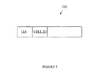
- FIG 5 a schematic overview of an internode packet 200 of a signaling protocol is shown.
- the internode packet comprises cell Load Information indicating user equipment Activity within a specific cell LIA.
- the specific cell may be identified by associating a cell ID, such as Cell Radio Network Temporary Identifier, C-RNTI, and/or the like, of the specific cell with the cell load information.
- examples herein disclose an internode signalling protocol comprising data indicating an identity of a local cell served by a second communication device and cell load information indicating user equipment activity within the local cell.
- the cell load information is arranged to be used to determine a power mode of the base station and/or devices associated to the base station.
- the internode signaling protocols may be X2 or S1 in LTE, lub/lur in WCDMA/HSPA, or Abis in GSM/EDGE.
- Examples of information to be conveyed may be:
- a base station signaling protocol is provided to be used to convey information indicating UE activity in a neighboring cell of a neighboring base station. This information is used by the receiving base station for taking decisions on power saving matters.
- the signaling protocols may, for example, be X2 or S1 in LTE, lub/lur in WCDMA/HSPA, and/or Abis in GSM/EDGE.
- X2 carries interference information, handover information, and by adding cell load information indicating UE activity the receiving base station may take a more planned decision regarding what power mode to enter.
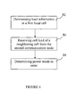
- FIG 6 a schematic overview of a method in a first communication device is shown. The method is for determining a power mode for a base station to enter.
- the first communication device determines cell load indicating user equipment activity within a first local cell of the base station.
- the first communication device receives cell load information from a second communication device comprising an indication of user equipment activity within a second cell associated to the second communication device.
- the first communication device determines the power mode for the base station to enter based on the received cell load information and the determined load in the first local cell.
- the first communication device may comprise a RNC, BSC, eNB, O&M and/or the like.
- the first communication device determines cell load information in a first local cell of a base station.
- the cell load information indicates UE activity in the first local cell.
- the first communication device comprises the base station and in some embodiments wherein the first communication device comprises a base station controller node, the cell load information, or parts of it, is retrieved/received from the base station serving the first base station over an interface such as lub and/or the like.
- the first communication device requests cell load of a neighboring second cell from a second communication device over the internode interface between the first and second communication device.
- the second communication device may be a RNC, BSC, eNB, O&M node and/or the like. This may be triggered when the determined cell load information in the first local cell load falls/exceeds a preset value indicating a certain level of UE activity in the local cell.
- the second communication device may request/receive user activity information from a base station serving the second cell in order to create cell load information to send as a response to the request from the first communication device.
- the first communication device receives cell load information from the second communication device comprising an indication of UE activity within the second cell associated to the second communication device. It should be understood that this information may previously been 'subscribed' to, i.e. data is sent by the second communication device without needing a specific request all the time. This information may also be information that is sent when triggered by a specific event such as when a cell load in a cell falls below a certain value indicating UE activity in the cell of the second communication device. It should be noted that the first communication device may receive cell load of a plurality of cells to take into account when determining power mode of the base station.
- the cell load information comprises; number of currently active user equipment, types of services being used, total amount of data being sent during a certain time window, locations of user equipments, number of Random Access operations during a certain time window, number of Non Access Stratum signalling messages passing through the cell during a certain time window, Terminal type of UEs, movement and direction information of UEs, and/or the like.
- the information may also be an activity report of present power mode of a neighbour base station implicitly indicating the UE activity in the neighbour cell.
- the second communication device also sends cell load information received from other communication devices to the first communication device. That is, the second communication device forwards cell load information.
- the first communication device may receive cell load information from a plurality of neighboring/adjacent cells.
- the first local cell and the second cell comprise different radio access technologies.
- the first communication device determines a power mode for the base station serving the first local cell to enter based on the received second cell load information and the determined cell load in the first local cell. It should here be understood that a plurality of cells from a plurality of base stations may be the base for the determination.
- the first communication device may perform the determination where the received second cell load is analysed separately or in conjunction with the determined cell load in the first local cell. For example, if a request to the second communication device is triggered when the first local cell has no UE activity, the first communication device need only to analyse the received second cell load to determine that a power mode. However, analysis may also be performed on the first local cell load and the second cell load.
- the first communication device determines a load value based on the received cell load information of the second cell and the determined load in the first local cell, wherein different ranges of the load value relates to different power modes.
- the first communication device also weight in other information such as handover statistics, and/or the like, when determining the power mode.
- the first communication device creates a message indicating the determined power mode and, as stated in an optional step 92, transmits the message to the base station serving the first local cell for the base station to enter the determined power mode. This may be the case when the determination of power mode is performed in a controller node or an O&M node controlling the base station.
- the received determined power mode order may trigger one or more internal orders in the base station to be created and transmitted out to auxiliary site equipment to change their power mode.
- the power mode of the auxiliary site equipment is based on the power mode of the base station.
- the first communication device may in some embodiments comprise the base station and enter the determined power mode.
- the determined power mode may be informed to other neighbouring base stations. These base stations may use this information in their turn to determine power mode of their own.
- the functions/acts noted in the blocks above in the method may occur out of the order noted in the operational illustrations.
- two blocks shown in succession may in fact be executed substantially concurrently or the blocks may sometimes be executed in the reverse order, depending upon the functionality/acts involved.
- the first communication device may comprise a base station, a base station controller, a combination thereof, and/or the like.
- the first communication device 10 comprises a control unit 101 arranged to determine cell load in a first local cell associated to the first communication device indicating user equipment activity within the first local cell. This information may be received/requested from a base station serving the first local cell.
- the first communication device 10 comprises a network interface 103 arranged to receive cell load information from a second communication device comprising an indication of user equipment activity within a second cell associated to the second communication device.
- the second communication device may in some embodiments comprise a base station such as a Base Station Transceiver BTS, NB, eNB, and/or the like.
- the second communication device may in some embodiments comprise a controller communication device such as a BSC, RNC, O&M, and/or the like, arranged to control/manage a base station.
- the first network interface 103 comprises an X2, lur, Abis interface and/or the like.
- the indication may in some embodiments comprise; number of currently active user equipment, types of services being used, total amount of data being sent during a certain time window, locations of user equipments, number of Random Access operations during a certain time window, number of Non Access Stratum signalling messages passing through the cell during a certain time window, terminal type of UEs, movement and direction information of UEs, power mode of a base station serving the second cell based on UE activity within the second cell and/or the like.
- the control unit 101 may further be arranged to request the cell load information from the second communication device over the first network interface 103.
- the cell load information from the second communication device may additionally or alternatively be sent to the first communication device from the second communication device, for example, if the information is subscribed to, periodically transmitted from the second communication device, or triggered when an event occurs at the second communication device.
- the control unit 101 is further arranged to determine a power mode for a base station serving the first local cell to enter based on the received cell load information and the determined load in the first local cell.
- the control unit 101 may be arranged to perform the determination in separated steps and/or a combined step analysing the received cell load together/merged with the determined cell load.
- control unit 101 is further arranged, in order to determine power mode to enter, to weight in other information, such as handover statistics, and/or the like.
- control unit 101 is further arranged, in order to determine power mode to enter, to determine a load value based on the received cell information and the determined load in the first local cell, wherein different ranges of the load value defines different power modes in a list stored in a memory unit 107.
- the first communication device such as an eNodeB, and/or the like, comprises the base station to power control.
- the control unit 101 is further arranged to enter the determined power mode, switching on/off different parts in the communication device according to determined power mode; settings of the different power modes are stored in a memory unit 107.
- the control unit may further be arranged to transmit an auxiliary power mode order to surrounding auxiliary equipment ordering the setting of surrounding equipment as well, such as air condition equipment, back-up battery equipment and/or the like, to a power mode based on the determined power mode.
- the first communication device comprises a network controller node such as a BSC, RNC, and/or the like, arranged to control the base station, or a controller node managing network nodes such as an O&M node.
- the control unit 101 may then further be arranged to create a message indicating the determined power mode, and to transmit the message over a second network interface 105 to a communication node serving the first local cell for the communication node to enter the determined power mode.
- the second network interface 105 may comprise an lub, Abis interface and/or the like.
- the first local cell and the second cell comprise different radio access technologies. That is, the control unit determines power mode to enter for a base station based on the load of a cell of a first radio access technology, for example, Evolved Universal Terrestrial Radio Access Network, E-UTRAN, combined with a load of a cell of a second radio access technology; for example, UMTS Terrestrial Radio Access Network (UTRAN)/GSM/Edge Radio Access Network (GERAN).
- E-UTRAN Evolved Universal Terrestrial Radio Access Network
- GERAN UMTS Terrestrial Radio Access Network
- the control unit 101 may comprise a CPU, a single processing unit, a plurality of processing units, and or the like.
- the memory unit 107 may comprise a single memory unit, a plurality of memory units, external and/or internal memory units.
- the first communication device and its components may be powered by and external power source connected to a power input 109 of the first communication.
- the first communication device may also be powered by an internal power source such as battery equipment and/or the like.
Landscapes
- Engineering & Computer Science (AREA)
- Computer Networks & Wireless Communication (AREA)
- Signal Processing (AREA)
- Mobile Radio Communication Systems (AREA)
Abstract
Description
- Embodiments herein refer to a base station and a method in a communications network, in particular, relating to power saving within the communications network.
- Saving electric power becomes of more importance in mobile networks. As data rates are increasing, the larger bandwidth implies increased power consumption for a base station. At the same time, operators are struggling with operational costs of the networks, in where the "electricity bill" is a non-negligible part of the operating expenses.
- Saving electric power in a base station can be done in different ways, such as: making power saving optimizations in the base station implementation, introducing newer more power efficient components, or introducing functionality where the base station partly powers off during low traffic periods.
- When introducing functionality to power off the base station or parts of the base station, decisions to power off/on is based on what is happening in the cells served by this particular base station.
- Patent document
WO 02/07464 A1, 24.01.2002 - Embodiments are disclosed herein to provide an efficient and reliable manner to save power in a base station.
- In some embodiments a method in a base station for determining a power mode for the base station to enter is disclosed. The base station determines cell load indicating user equipment activity within a first local cell of the base station and receives cell load information from a communication device comprising an indication of user equipment activity within a second cell associated to the communication device. The base station determines the power mode for the base station to enter based on the received cell load information and the determined load in the first local cell.
- In order to perform the method a base station is provided. The base station comprises a control unit arranged to determine cell load in a first local cell associated to the base station indicating user equipment activity within the first local cell. Furthermore, the base station comprises a network interface arranged to receive cell load information from a communication device comprising an indication of user equipment activity within a second cell associated to the communication device. The control unit is further arranged to determine a power mode for the base station to enter, the base station serving the first local cell, based on the received cell load information and the determined load in the first local cell.
- Examples herein disclose ways to make more intelligent decisions regarding the power mode in a base station resulting in a more efficient and reliable manner.
- Embodiments will now be described in more detail in relation to the enclosed drawings, in which:
-
Figure 1 shows a schematic overview of a communications network, -
Figure 2 shows a schematic overview of a combined method and signaling scheme in an Evolved Packet System, EPS, network, -
Figure 3 shows an example of a combined method and signaling scheme of an EPS network, -
Figure 4 shows a schematic overview of a Radio Access Network, RAN, in a Universal Mobile Telecommunications System, UMTS, network, -
Figure 5 shows a schematic overview of an internode packet, -
Figure 6 show an embodiment of a method in a first communication device, -
Figure 7 shows a schematic overview of a method in a first communication device, and -
Figure 8 shows a schematic overview of a first communication device. - Embodiments of the present invention will be described more fully hereinafter with reference to the accompanying drawings, in which embodiments of the invention are shown. This invention may, however, be embodied in many different forms and should not be construed as limited to the embodiments set forth herein. Rather, these embodiments are provided so that this disclosure will be thorough and complete, and will fully convey the scope of the invention to those skilled in the art. Like numbers refer to like elements throughout.
- The terminology used herein is for the purpose of describing particular embodiments only and is not intended to be limiting of the invention. As used herein, the singular forms "a", "an" and "the" are intended to include the plural forms as well, unless the context clearly indicates otherwise. It will be further understood that the terms "comprises" and/or "comprising," when used herein, specify the presence of stated features, integers, steps, operations, elements, and/or components, but do not preclude the presence or addition of one or more other features, integers, steps, operations, elements, components, and/or groups thereof.
- Unless otherwise defined, all terms (including technical and scientific terms) used herein have the same meaning as commonly understood by one of ordinary skill in the art to which this invention belongs. It will be further understood that terms used herein should be interpreted as having a meaning that is consistent with their meaning in the context of this specification and the relevant art and will not be interpreted in an idealized or overly formal sense unless expressly so defined herein.
- In
figure 1 , a schematic overview of a communications network is disclosed. - A
first communication device 10, for example, a base station or the like, comprises a power saving function. Asecond communication device 20, for example, a base station, a controller node, and/or the like, comprises information of User Equipment (UE) 100 activity within a cell B. Thesecond communication device 20 transmits cell load information indicating UE activity within the cell B over an Internode connection IC to thefirst communication device 10. This may be sent as a response to a request from afirst communication device 10, but may also be information previously 'subscribed' to, i.e. data is sent by neighboring cells without needing a specific request all the time. It could also be information that is sent triggered when a specific event occurs. - The
first communication device 10 receives the cell load information indicating UE activity in the cell B over the IC and analyses the information separately and/or in conjunction with local cell load information indicating UE activity in a local cell A controlled/served by the first communication device. Based on the analysis thefirst communication device 10 takes a power mode decision and sets itself up into the determined power mode. Hence, the first communication device determines what power mode to enter based on local and neighboring cell information. It should here be understood that the determined power mode may be sent to a base station comprising the cell A, if the decision is taken in a node controlling the base station of cell A. - In
figure 2 , a schematic overview of a combined method and signaling scheme in an EPS network is shown. - In this example the Long Term Evolution, LTE, architecture is used as an example, but the idea may also apply for the 2G/3G RAN architecture or similar architectures.
- A base station, enhanced Node B (eNB) 10, is designed so that it can enter one or several power modes, i.e. if the base station detects that some of its hardware is not needed (due to for example low traffic periods) it can be switched off in order to save power. There could be several different levels of power saving, in terms of which hardware that is powered off, but also the state of the specific hardware (for example: fully operational, hot standby, powered off).
- In LTE neighbor base stations eNBs 10, 20 are connected by means of an X2 interface. This means that neighbor base stations eNB 10, eNB 20 may exchange signaling information over this connection.
- In step A1, the eNB 10 determines the cell load of a local cell within the
eNB 10 and requests the cell load of a neighbor cell, adjacent the local cell, of theeNB 20. The cell load comprises an indication of UE activity within the cell. - In step A2, the eNB 20 receives the request and determines the UE activity within the requested cell and transmits the cell load comprising an indication of the determined UE activity with the cell.
- The signaling protocol X2, in the illustrated example, comprises information about current UE activity in a cell of the neighbor eNB 20. This means that the eNB 20 may inform its neighbor eNBs about current UE activity within a cell of the eNB 20. Examples of information to be conveyed:
- Number of currently active UEs (i.e. UEs that are currently actively transmitting or receiving data)
- Types of services being used (such as real-time/best-effort services)
- Total amount of sent/received data in the cell since last report
- Location of the UE (if available)
- Number of random accesses since last report (or Random Access Channel, RACH, load)
- Number of Non-Access Stratum, NAS, signaling messages that are passing through a cell
- Terminal type of UEs,
- Power mode of the
eNB 20 indicating a certain level of UE activity within the cell of theeNB 20, - Movement and direction information of UEs, information about speed and direction so if a UE is moving towards a cell with high speed it could be useful info to e.g. trigger a faster power-on. Speed may be known from vehicle speed and/or the like.
- The reports may be sent periodically or on demand from the
eNB 10/an Operation and Maintenance O&M node. Rules could be defined so that reports are sent under certain conditions , e.g. a report should always be sent when then number of active users goes from 0 to >0, and/or a report should be sent when number of active user goes down to 0. - In step A3, the
eNB 10 receives the report and analyses the cell load indicating the UE activity of the neighbor cell separately or together with the determined local cell load indicating the UE activity of the local cell. - In step A4, the
eNB 10 determines a power mode for theeNB 10 to enter based on the analysis and enters the determined power mode. - When receiving a report about the neighbor cells activity from one or more eNbs, the receiving
base station eNB 10 could take a decision on how to perform power saving. The exact algorithm to do so may be manufacturer dependent, but examples could be: - If there is no activity in all neighbor cells (typically in the middle of the night), and there are no active users in the own cells, power saving can be started.
- If there is no activity in a specific cell, and (by O&M configuration) the base station knows that this cell completely covers its own coverage area, the base station could be completely powered off (for example a macro cell covering several micro cells).
- If the base station is already in a power saving state, and receives information about activity in neighbor cells, selected parts of the base station can be powered up or put in "hot standby".
- A change in power mode of the base station also may affect how auxiliary site equipment, such as air-condition, battery back-up system etc, is used. That is, the auxiliary site equipment can be controlled on the basis of the power consumption of the base station and also enter different power modes based on the power mode of the base station.
- More advanced schemes may be envisioned, for example, by also weighting in handover statistics or information about the positions of the active UEs. Such information could be used to estimate the probability that the cell in question will need to take traffic in the close future. For example: if there is activity in a neighbor cell to which a cell frequently receives incoming handovers, it is likely that some UEs will be handed over in the future if there has been reported about activity in that neighbor cell.
- To limit frequent changes between power-on and power-off states certain time limitations can be used. For example, a cell load may be determined over a preset time window.
- The base station has little knowledge about the UEs in the area outside its own local cell/s coverage area. As a consequence, decisions to power off/power on have to be based on what is happening only in the cells served by this particular base station. But by making the base station aware of the UEs in the neighboring areas, more intelligent decisions can be made. As the base station is typically waiting for UEs to initiate activity (that may occur as a response to a message transmitted by the base station), a minimum set of equipment has always to be switched on, for example, to transmit broadcast information, and listening for UEs wanting to initiate communication. By making the base station aware of the UEs in the neighboring cells the level of power saving mode may be increased as the information underlying the decision is based on wider data making it more reliable. For example, if the base station knows that the activity in neighboring cells is very low as well as in its own cell/s the power required, for example, for listening for UEs and/or the like, may be reduced much more than if the information of the neighboring cell is not known.
- It can also be envisioned that similar functionality could be conveyed via the O&M systems instead of the traffic interfaces, as here exemplified. UE activity would then be reported to the O&M system that takes care of distributing the relevant information to the particular cells neighbors.
- In
figure 3 , an example of a combined method and signaling scheme of an EPS network comprising anO&M node 40 is shown. A firstbase station eNB 10 and a secondbase station eNB 20 is connected to anO&M node 40 over O&M interfaces, O&M-I. - In step B1, the
eNB 20 reports a cell load indicating UE activity in a local cell of theeNB 20. This may be triggered by an event such as there is no activity in the local cell and/or the like, may be reported periodically, and/or the like. - In step B2, the
O&M node 40 stores the report. - In step B3, the
eNB 10 determines the cell load indicating UE activity within a local cell of theeNB 10. As the cell load indicates a power mode change theeNB 10 requests a cell load of a neighbor cell from theO&M node 40, for example, if there is no UE activity in the local cell. - In step B4, the
O&M node 40 receives the request and based on the cell ID of the requested cell in the request theO&M node 40 retrieves the stored cell load indicating the UE activity of the requested cell; the requested cell being the local cell of theeNB 20. TheO&M node 40 then transmits the stored cell load of the requested cell in a report to theeNB 10. - In step B5, the
eNB 10 receives the report and analyses the cell load indicating the UE activity in the neighbor cell separate or together with the cell load indicating the UE activity in the local cell and determines a power mode to enter/keep. - In step B6, the
eNB 10 enters the determined power mode. It should also be understood that theeNB 10 may also send out an order to auxiliary equipment supporting theeNB 10 to enter a supporting power mode based on the entered power mode. For example, if power is reduced, that is "a change in power mode", this may also affect how the auxiliary site equipment is used. That is, the supporting equipment may be controlled on the basis of the power consumption of the base station. - In some embodiments, the changed power mode such as reduced power mode/ full power mode and/or the like is also transmitted to neighbouring eNBs providing knowledge for the eNB of power modes of neighbouring cells. This power mode report may in fact be used in order to determine power mode of the local base station. A power mode report may be considered as a report of a cell load indicating UE activity in a neighboring cell.
- It should also be noted that in some embodiments the
O&M node 40 receives reports of the cell load indicating the UE activity of different cells and may, based on the reports, determine a power mode for a certain base station to operate in. TheO&M node 40 may then send out an order to the base stations/controller to enter certain power modes. That is, in some embodiments the determination is performed in theO&M node 40. - Although these examples are for the LTE architecture, similar information could be conveyed to the 2G/3G base stations. In this case it will be the Base Station Controller/Radio Network Controller BSC/RNC respectively that provides the Radio Base Station/NodeB RBS/NB with power mode information based on the load of the neighbor cells.
- In
figure 4 , a schematic overview of a Radio Access Network, RAN, in an UMTS network is shown. - In the illustrated example, the RAN comprises a first base station NB 12 connected to a first Radio
Network Controller RNC 10 over an lub Interface. Furthermore, the RAN comprises a second base station NB 22 connected to a second RadioNetwork Controller RNC 20 over an lub Interface. Thefirst RNC 10 is connected over an lur Interface to thesecond RNC 20. - The
second RNC 20 receives reports of cell load indicating UE activity in a cell of the second NB 22 from the second NB 22 and determines the cell load in the cell of the second NB 22. - The
first RNC 10 receives reports from the first NB 12 and determines a cell load indicating the UE activity in a cell of the first NB 12. Then thefirst RNC 10 may request a cell load of the neighbor cell from the second NB 22. The request is sent to thesecond RNC 20 over the lur Interface. Thesecond RNC 20 sends a report on the cell load indicating the UE activity in the cell of the second NB 22, being the neighbor cell of the cell of the first NB 12, to thefirst RNC 10 over the lur Interface. - Based on the received report from the
second RNC 20 and the determined cell load indicating UE activity in the cell of the first NB 12, thefirst RNC 10 determines a power mode for the first NB 12. Thefirst RNC 10 then transmits the determined power mode to the first NB 12 and the first NB 12 enters the power mode. - The technique may also be used across radio access networks, so that lack of traffic in one access technology is reported and acted upon in another. For example: In the night the operator may steer all traffic to LTE, and the 2G/3G networks are powered down to a minimum capacity configuration. In this case, signaling between access technologies may be done via the Core Network, CN, an O&M interface/proprietary interface, and/or the like.
- Another option is to perform proprietary signaling between base stations of different access technologies that are located in the same base station site.
- In
figure 5 , a schematic overview of aninternode packet 200 of a signaling protocol is shown. - The internode packet comprises cell Load Information indicating user equipment Activity within a specific cell LIA. The specific cell may be identified by associating a cell ID, such as Cell Radio Network Temporary Identifier, C-RNTI, and/or the like, of the specific cell with the cell load information.
- Hence, examples herein disclose an internode signalling protocol comprising data indicating an identity of a local cell served by a second communication device and cell load information indicating user equipment activity within the local cell. The cell load information is arranged to be used to determine a power mode of the base station and/or devices associated to the base station.
- The internode signaling protocols may be X2 or S1 in LTE, lub/lur in WCDMA/HSPA, or Abis in GSM/EDGE.
- Examples of information to be conveyed may be:
- Number of currently active UEs (i.e. UEs that are currently actively transmitting or receiving data)
- Types of services being used (such as real-time/best-effort services)
- Total amount of sent/received data in the cell since last report
- Location of the UE (if available)
- Number of random accesses since last report (or Random Access Channel, RACH, load)
- Number of NAS signaling messages that are passing through a cell
- Terminal type of UEs,
- Power mode of the base station serving the requested cell indicating a certain level of UE activity,
- Movement and direction information of UEs, information about speed and direction so if a UE is moving towards a cell with high speed it could be useful info to e.g. trigger a faster power-on. Speed may be known from vehicle speed and/or the like.
- A base station signaling protocol is provided to be used to convey information indicating UE activity in a neighboring cell of a neighboring base station. This information is used by the receiving base station for taking decisions on power saving matters. The signaling protocols may, for example, be X2 or S1 in LTE, lub/lur in WCDMA/HSPA, and/or Abis in GSM/EDGE. For example, X2 carries interference information, handover information, and by adding cell load information indicating UE activity the receiving base station may take a more planned decision regarding what power mode to enter.
- In
figure 6 , a schematic overview of a method in a first communication device is shown. The method is for determining a power mode for a base station to enter. - In
step 82, the first communication device determines cell load indicating user equipment activity within a first local cell of the base station. - In
step 86, the first communication device receives cell load information from a second communication device comprising an indication of user equipment activity within a second cell associated to the second communication device. - In
step 88, the first communication device determines the power mode for the base station to enter based on the received cell load information and the determined load in the first local cell. - In
figure 7 , a schematic overview of a method in a first communication device is shown. The first communication device may comprise a RNC, BSC, eNB, O&M and/or the like. - In
step 82, the first communication device determines cell load information in a first local cell of a base station. The cell load information indicates UE activity in the first local cell. In some embodiments, the first communication device comprises the base station and in some embodiments wherein the first communication device comprises a base station controller node, the cell load information, or parts of it, is retrieved/received from the base station serving the first base station over an interface such as lub and/or the like. - In
optional step 84, the first communication device requests cell load of a neighboring second cell from a second communication device over the internode interface between the first and second communication device. The second communication device may be a RNC, BSC, eNB, O&M node and/or the like. This may be triggered when the determined cell load information in the first local cell load falls/exceeds a preset value indicating a certain level of UE activity in the local cell. - It should here be understood that the second communication device may request/receive user activity information from a base station serving the second cell in order to create cell load information to send as a response to the request from the first communication device.
- In
step 86, the first communication device receives cell load information from the second communication device comprising an indication of UE activity within the second cell associated to the second communication device. It should be understood that this information may previously been 'subscribed' to, i.e. data is sent by the second communication device without needing a specific request all the time. This information may also be information that is sent when triggered by a specific event such as when a cell load in a cell falls below a certain value indicating UE activity in the cell of the second communication device. It should be noted that the first communication device may receive cell load of a plurality of cells to take into account when determining power mode of the base station. - In some embodiments, the cell load information comprises; number of currently active user equipment, types of services being used, total amount of data being sent during a certain time window, locations of user equipments, number of Random Access operations during a certain time window, number of Non Access Stratum signalling messages passing through the cell during a certain time window, Terminal type of UEs, movement and direction information of UEs, and/or the like. The information may also be an activity report of present power mode of a neighbour base station implicitly indicating the UE activity in the neighbour cell.
- In some embodiments, the second communication device also sends cell load information received from other communication devices to the first communication device. That is, the second communication device forwards cell load information. Thus, the first communication device may receive cell load information from a plurality of neighboring/adjacent cells.
- In some embodiments, the first local cell and the second cell comprise different radio access technologies.
- In
step 88, the first communication device determines a power mode for the base station serving the first local cell to enter based on the received second cell load information and the determined cell load in the first local cell. It should here be understood that a plurality of cells from a plurality of base stations may be the base for the determination. The first communication device may perform the determination where the received second cell load is analysed separately or in conjunction with the determined cell load in the first local cell. For example, if a request to the second communication device is triggered when the first local cell has no UE activity, the first communication device need only to analyse the received second cell load to determine that a power mode. However, analysis may also be performed on the first local cell load and the second cell load. - In some embodiments, the first communication device determines a load value based on the received cell load information of the second cell and the determined load in the first local cell, wherein different ranges of the load value relates to different power modes.
- In some embodiments, the first communication device also weight in other information such as handover statistics, and/or the like, when determining the power mode.
- In
optional step 90, the first communication device creates a message indicating the determined power mode and, as stated in anoptional step 92, transmits the message to the base station serving the first local cell for the base station to enter the determined power mode. This may be the case when the determination of power mode is performed in a controller node or an O&M node controlling the base station. - In some embodiments, the received determined power mode order may trigger one or more internal orders in the base station to be created and transmitted out to auxiliary site equipment to change their power mode. Thus, the power mode of the auxiliary site equipment is based on the power mode of the base station.
- Alternatively, in
step 94, the first communication device may in some embodiments comprise the base station and enter the determined power mode. - It should also be noted that the determined power mode may be informed to other neighbouring base stations. These base stations may use this information in their turn to determine power mode of their own.
- In some implementations, the functions/acts noted in the blocks above in the method may occur out of the order noted in the operational illustrations. For example, two blocks shown in succession may in fact be executed substantially concurrently or the blocks may sometimes be executed in the reverse order, depending upon the functionality/acts involved.
- In order to perform the method a first communication device is provided. The first communication device may comprise a base station, a base station controller, a combination thereof, and/or the like.
- In
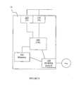
figure 8 , a schematic overview of afirst communication device 10 is shown. Thefirst communication device 10 comprises acontrol unit 101 arranged to determine cell load in a first local cell associated to the first communication device indicating user equipment activity within the first local cell. This information may be received/requested from a base station serving the first local cell. - The
first communication device 10 comprises anetwork interface 103 arranged to receive cell load information from a second communication device comprising an indication of user equipment activity within a second cell associated to the second communication device. - The second communication device may in some embodiments comprise a base station such as a Base Station Transceiver BTS, NB, eNB, and/or the like. The second communication device may in some embodiments comprise a controller communication device such as a BSC, RNC, O&M, and/or the like, arranged to control/manage a base station.
- In some embodiments, the
first network interface 103 comprises an X2, lur, Abis interface and/or the like. - The indication may in some embodiments comprise; number of currently active user equipment, types of services being used, total amount of data being sent during a certain time window, locations of user equipments, number of Random Access operations during a certain time window, number of Non Access Stratum signalling messages passing through the cell during a certain time window, terminal type of UEs, movement and direction information of UEs, power mode of a base station serving the second cell based on UE activity within the second cell and/or the like.
- The
control unit 101 may further be arranged to request the cell load information from the second communication device over thefirst network interface 103. The cell load information from the second communication device may additionally or alternatively be sent to the first communication device from the second communication device, for example, if the information is subscribed to, periodically transmitted from the second communication device, or triggered when an event occurs at the second communication device. - The
control unit 101 is further arranged to determine a power mode for a base station serving the first local cell to enter based on the received cell load information and the determined load in the first local cell. Thecontrol unit 101 may be arranged to perform the determination in separated steps and/or a combined step analysing the received cell load together/merged with the determined cell load. - In some embodiments, the
control unit 101 is further arranged, in order to determine power mode to enter, to weight in other information, such as handover statistics, and/or the like. - In some embodiments, the
control unit 101 is further arranged, in order to determine power mode to enter, to determine a load value based on the received cell information and the determined load in the first local cell, wherein different ranges of the load value defines different power modes in a list stored in amemory unit 107. - In some embodiments, the first communication device, such as an eNodeB, and/or the like, comprises the base station to power control. Thus, the
control unit 101 is further arranged to enter the determined power mode, switching on/off different parts in the communication device according to determined power mode; settings of the different power modes are stored in amemory unit 107. The control unit may further be arranged to transmit an auxiliary power mode order to surrounding auxiliary equipment ordering the setting of surrounding equipment as well, such as air condition equipment, back-up battery equipment and/or the like, to a power mode based on the determined power mode. - In some embodiments, the first communication device comprises a network controller node such as a BSC, RNC, and/or the like, arranged to control the base station, or a controller node managing network nodes such as an O&M node. The
control unit 101 may then further be arranged to create a message indicating the determined power mode, and to transmit the message over asecond network interface 105 to a communication node serving the first local cell for the communication node to enter the determined power mode. - The
second network interface 105 may comprise an lub, Abis interface and/or the like. - In some embodiments, the first local cell and the second cell comprise different radio access technologies. That is, the control unit determines power mode to enter for a base station based on the load of a cell of a first radio access technology, for example, Evolved Universal Terrestrial Radio Access Network, E-UTRAN, combined with a load of a cell of a second radio access technology; for example, UMTS Terrestrial Radio Access Network (UTRAN)/GSM/Edge Radio Access Network (GERAN).
- The
control unit 101 may comprise a CPU, a single processing unit, a plurality of processing units, and or the like. - The
memory unit 107 may comprise a single memory unit, a plurality of memory units, external and/or internal memory units. - The first communication device and its components may be powered by and external power source connected to a
power input 109 of the first communication. The first communication device may also be powered by an internal power source such as battery equipment and/or the like. - In the drawings and specification, there have been disclosed exemplary embodiments of the invention. However, many variations and modifications can be made to these embodiments without substantially departing from the principles of the present invention. Accordingly, although specific terms are employed, they are used in a generic and descriptive sense only and not for purposes of limitation, the scope of the invention being defined by the following claims.
Claims (18)
- A method in a base station (10) for determining a power mode for the base station to enter, comprising the steps of- determining (82) cell load indicating user equipment activity within a first local cell of the base station (10), characterized by- receiving (86) cell load information from a communication device comprising an indication of user equipment activity within a second cell associated to the communication device, and- determining (88) the power mode for the base station (10) to enter based on the received cell load information and the determined load in the first local cell.
- A method according to claim 1, wherein the step of determining power mode comprises to determine a load value based on the received cell load information of the second cell and the determined load in the first local cell, wherein different ranges of the load value relates to different power modes.
- A method according to any of claims 1-2, wherein the indication comprises;
number of currently active user equipment, types of services being used,
total amount of data being sent during a certain time window, locations of user equipments, number of Random Access operations during a certain time window, number of Non Access Stratum signaling messages passing through the cell during a certain time window, terminal type of user equipment, movement and direction information of user equipment, power mode of a base station serving the second cell based on UE activity within the second cell and/or the like. - A method according to any of claims 1-3, wherein the step of determining power mode further comprises to weight in other information such as handover statistics, and/or the like.
- A method according to any of claims 1-4, wherein the first local cell and the second cell comprise different radio access technologies.
- A method according to any of the claims 1-5, further comprising the step of requesting (84) the cell load information from the communication device.
- A method according to any of claims 1-6, further comprising the step of entering (94) the determined power mode.
- A method according to claim 1-7, wherein the base station creates and transmits auxiliary power mode orders to auxiliary equipment supporting the base station, wherein the auxiliary power mode order is based on the determined power mode of the base station.
- A base station (10) comprising a control unit (101) arranged to determine cell load in a first local cell associated to the base station (10) indicating user equipment activity within the first local cell, characterized by comprising a network interface (103) arranged to receive cell load information from a communication device comprising an indication of user equipment activity within a second cell associated to the communication device, wherein the control unit (101) is further arranged to determine a power mode for the base station (10) to enter, the base station (10) serving the first local cell, based on the received cell load information and the determined load in the first local cell.
- A base station (10) according to claim 9, wherein the control unit (101) is further arranged, in order to determine power mode to enter, to determine a load value based on the received cell information and the determined load in the first local cell, wherein different ranges of the load value defines different power modes in a list stored in a memory unit (107).
- A base station (10) according to any of the claims 9-10, wherein the indication comprises; number of currently active user equipment, types of services being used, total amount of data being sent during a certain time window, locations of user equipments, number of Random Access operations during a certain time window, number of Non Access Stratum signaling messages passing through the cell during a certain time window, terminal type of user equipment, movement and direction information of user equipment, power mode of a base station serving the second cell based on user equipment activity within the second cell, and/or the like.
- A base station (10) according to any of the claims 9-11, wherein the control unit (101) is further arranged, in order to determine power mode to enter, to weight in other information, such as handover statistics, and/or the like.
- A base station (10) according to any of the claims 9-12, wherein the first cell and the second cell comprise different radio access technologies.
- A base station (10) according to any of claims 9-13, wherein the control unit (101) is furthermore arranged to create and transmit an auxiliary power mode order to auxiliary equipment supporting the base station stating an auxiliary power mode to enter based on the determined power mode.
- A base station (10) according to any of the claims 9-14, wherein the control unit (101) is further arranged to enter the determined power mode, switching on/off different parts in the base station according to determined power mode, settings of the different power modes are stored in a memory unit (107).
- A base station (10) according to any of claims 9-15, wherein the base station is an eNodeB, and/or he like.
- A base station (10) according to any of claims 9-16, wherein the first network interface (103) comprises an X2, lur, Abis interface and/or the like.
- A base station (10) according to any of claims 9-17, wherein the control unit (101) is further arranged to request the cell load information from the second communication device over the first network interface (103).
Applications Claiming Priority (1)
| Application Number | Priority Date | Filing Date | Title |
|---|---|---|---|
| PCT/SE2008/051567 WO2010077193A1 (en) | 2008-12-29 | 2008-12-29 | Device, packet and method for power saving |
Publications (2)
| Publication Number | Publication Date |
|---|---|
| EP2371168A1 EP2371168A1 (en) | 2011-10-05 |
| EP2371168B1 true EP2371168B1 (en) | 2013-08-28 |
Family
ID=41037789
Family Applications (1)
| Application Number | Title | Priority Date | Filing Date |
|---|---|---|---|
| EP08876333.9A Not-in-force EP2371168B1 (en) | 2008-12-29 | 2008-12-29 | Method and base station for power saving |
Country Status (4)
| Country | Link |
|---|---|
| US (1) | US20120008512A1 (en) |
| EP (1) | EP2371168B1 (en) |
| ES (1) | ES2436786T3 (en) |
| WO (1) | WO2010077193A1 (en) |
Families Citing this family (25)
| Publication number | Priority date | Publication date | Assignee | Title |
|---|---|---|---|---|
| WO2010130104A1 (en) * | 2009-05-15 | 2010-11-18 | 华为终端有限公司 | Method, device and system for controlling access point |
| CN101965038B (en) * | 2009-07-23 | 2015-06-10 | 中兴通讯股份有限公司 | Energy-saving control method and device of base station between systems |
| CN102714859B (en) * | 2010-01-21 | 2016-05-25 | Lg电子株式会社 | 1X Message Bundle |
| KR20110102589A (en) * | 2010-03-11 | 2011-09-19 | 삼성전자주식회사 | Apparatus and method for reducing power consumption in a wireless communication system |
| US8554224B2 (en) * | 2010-03-24 | 2013-10-08 | Qualcomm Incorporated | Cellular network energy saving |
| US9294972B2 (en) * | 2010-04-28 | 2016-03-22 | Qualcomm Incorporated | Neighbor relation information management |
| US9264954B2 (en) | 2010-04-28 | 2016-02-16 | Qualcomm Incorporated | Neighbor relation information management |
| US8902791B2 (en) * | 2010-10-01 | 2014-12-02 | Qualcomm Incorporated | Configuration control of inter-cell signaling based on power state |
| GB201018211D0 (en) | 2010-10-28 | 2010-12-15 | Vodafone Ip Licensing Ltd | Smart cell activation |
| CN102026357B (en) * | 2010-12-17 | 2014-02-26 | 华为技术有限公司 | Power control method and device for base station |
| EP2721880B1 (en) * | 2011-06-16 | 2019-01-16 | Telefonaktiebolaget LM Ericsson (publ) | Method and arrangement in a network node |
| CN102388643B (en) * | 2011-09-19 | 2013-12-04 | 华为技术有限公司 | Load forecast method, device and energy-saving control communication system |
| KR101872883B1 (en) * | 2011-12-15 | 2018-07-03 | 한국전자통신연구원 | Base station and operating method of base station |
| WO2013110213A1 (en) * | 2012-01-27 | 2013-08-01 | Telefonaktiebolaget L M Ericsson(Publ) | Method and apparatus for dynamic and adjustable energy savings in a communication network |
| US8971226B2 (en) | 2012-01-27 | 2015-03-03 | Telefonaktiebolaget L M Ericsson (Publ) | Method and apparatus for dynamic and adjustable energy savings in a communication network |
| US8515410B1 (en) * | 2012-05-21 | 2013-08-20 | Nokia Siemens Networks Oy | Enabling different base station ES levels based on time to activate cell |
| US10200844B2 (en) * | 2012-08-23 | 2019-02-05 | Nokia Solutions And Networks Oy | Massive discovery of devices |
| CN104126324B (en) * | 2013-02-08 | 2018-09-07 | 华为技术有限公司 | Wireless access point control method and related equipment and system |
| WO2014129714A1 (en) * | 2013-02-20 | 2014-08-28 | Lg Electronics Inc. | Method and apparatus for transmitting cell load information in wireless communication system |
| JP6169167B2 (en) * | 2013-04-05 | 2017-07-26 | 京セラ株式会社 | Base station, processor, and mobile communication system |
| US11089486B2 (en) * | 2013-10-24 | 2021-08-10 | Convida Wireless | Service coverage management systems and methods |
| CN104333896B (en) * | 2014-11-28 | 2018-12-25 | 东莞宇龙通信科技有限公司 | Microcell base station and its method of adjustment and adjustment system for sending power |
| US20170273017A1 (en) * | 2016-03-18 | 2017-09-21 | Qualcomm Incorporated | Request-to-send/clear-to-send enabled power saving and off-channel operations |
| US11224095B2 (en) | 2020-03-06 | 2022-01-11 | Motorola Solutions, Inc. | Adaptive operation of a control channel of a radio frequency site controller |
| GB2604685A (en) * | 2020-10-30 | 2022-09-14 | Samsung Electronics Co Ltd | Improvements in and relating to Self-Organised Networks (SONs) |
Family Cites Families (33)
| Publication number | Priority date | Publication date | Assignee | Title |
|---|---|---|---|---|
| US5790534A (en) * | 1996-09-20 | 1998-08-04 | Nokia Mobile Phones Limited | Load control method and apparatus for CDMA cellular system having circuit and packet switched terminals |
| US6360106B1 (en) * | 1996-12-09 | 2002-03-19 | Siemens Aktiengesellschaft | Base station for a radio communications system |
| FI108764B (en) * | 1997-05-28 | 2002-03-15 | Nokia Corp | Control of the transmitter-receiver unit in a cellular radio system |
| US6343213B1 (en) * | 1997-10-24 | 2002-01-29 | Nortel Networks Limited | Method to protect against interference from mobile radios |
| US6275478B1 (en) * | 1998-07-10 | 2001-08-14 | Qualcomm Incorporated | Methods and apparatuses for fast power control of signals transmitted on a multiple access channel |
| DE69826898T2 (en) * | 1998-12-18 | 2005-10-13 | Nokia Corp. | METHOD FOR TRAFFIC LOAD CONTROL IN A TELECOMMUNICATIONS NETWORK |
| US6584330B1 (en) * | 2000-07-18 | 2003-06-24 | Telefonaktiebolaget Lm Ericsson (Publ) | Adaptive power management for a node of a cellular telecommunications network |
| US6799030B2 (en) * | 2000-10-11 | 2004-09-28 | Novatel Wireless, Inc. | Method and apparatus for low power operation of an RF wireless modem |
| CN1135746C (en) * | 2000-10-19 | 2004-01-21 | 华为技术有限公司 | Multiple-job load monitoring and forecasting device in CDMA cellular communication system and its calculation method |
| GB2396523B (en) * | 2002-12-17 | 2006-01-25 | Motorola Inc | Method and apparatus for power control for a transmitter in a cellular communication system |
| US7460862B2 (en) * | 2003-01-29 | 2008-12-02 | Nokia Corporation | Solution for managing user equipment version information in a mobile communications network |
| FR2854533B1 (en) * | 2003-04-30 | 2005-09-30 | France Telecom | CHARGE CONTROL DEVICE AND METHOD WITH POWER CONTROL |
| JP2005117357A (en) * | 2003-10-08 | 2005-04-28 | Nec Corp | Method and system for managing radio communication system, and managing apparatus |
| US20050135313A1 (en) * | 2003-12-23 | 2005-06-23 | Gandhi Asif D. | Method for determining when to increase capacity in a wireless communications system |
| WO2005094103A1 (en) * | 2004-03-25 | 2005-10-06 | Research In Motion Limited | Wireless access point methods and apparatus for reduced power consumption and cost |
| JP4519606B2 (en) * | 2004-11-05 | 2010-08-04 | 株式会社エヌ・ティ・ティ・ドコモ | Base station, mobile communication system, and transmission power control method |
| US7702352B2 (en) * | 2005-05-13 | 2010-04-20 | Intel Corporation | Network node power management methods and apparatus |
| US8009635B2 (en) * | 2005-09-09 | 2011-08-30 | Mcmaster University | Reducing handoff latency in a wireless local area network through an activation alert that affects a power state of a receiving mesh access point |
| US7756548B2 (en) * | 2005-09-19 | 2010-07-13 | Qualcomm Incorporated | Methods and apparatus for use in a wireless communications system that uses a multi-mode base station |
| US7567791B2 (en) * | 2005-09-19 | 2009-07-28 | Qualcomm Incorporated | Wireless terminal methods and apparatus for use in a wireless communications system that uses a multi-mode base station |
| US8989084B2 (en) * | 2005-10-14 | 2015-03-24 | Qualcomm Incorporated | Methods and apparatus for broadcasting loading information corresponding to neighboring base stations |
| JP2007195076A (en) * | 2006-01-20 | 2007-08-02 | Nec Corp | Radio communication system, and transmission power control method and device thereof |
| US7853282B2 (en) * | 2006-09-14 | 2010-12-14 | Qualcomm Incorporated | Power allocation in a wireless communication system |
| US7774000B2 (en) * | 2007-01-31 | 2010-08-10 | Research In Motion Limited | Loading control methods and apparatus for wireless access points of wireless local area networks in support of legacy terminals |
| WO2008120159A2 (en) * | 2007-03-30 | 2008-10-09 | Nokia Corporation | System and method for self-optimization of interference coordination in communication systems |
| US8909278B2 (en) * | 2007-12-21 | 2014-12-09 | Airvana Lp | Adjusting wireless signal transmission power |
| US8638759B2 (en) * | 2008-01-30 | 2014-01-28 | Qualcomm Incorporated | Serving cell selection in wireless communications |
| US8687588B2 (en) * | 2008-07-02 | 2014-04-01 | Qualcomm Incorporated | Low power modes for femto cells |
| US8023444B2 (en) * | 2008-07-03 | 2011-09-20 | Cisco Technology, Inc. | Multiple density configurations and algorithms for intelligent power savings infrastructure in wireless LANs |
| US8411606B2 (en) * | 2008-10-31 | 2013-04-02 | Fujitsu Limited | System and method for incorporating a low power mode in wireless communication |
| US8447368B2 (en) * | 2008-11-13 | 2013-05-21 | Lantiq Deutschland Gmbh | Base station, method of operating a base station and wireless communication system |
| US20100128645A1 (en) * | 2008-11-26 | 2010-05-27 | Murata Manufacturing Co., Ltd. | System and method for adaptive power conservation based on traffic profiles |
| US9264993B2 (en) * | 2008-12-15 | 2016-02-16 | Lg Electronics Inc. | Method for saving power of a femto base station using sleep period synchronization |
-
2008
- 2008-12-29 WO PCT/SE2008/051567 patent/WO2010077193A1/en not_active Ceased
- 2008-12-29 US US13/142,723 patent/US20120008512A1/en not_active Abandoned
- 2008-12-29 EP EP08876333.9A patent/EP2371168B1/en not_active Not-in-force
- 2008-12-29 ES ES08876333.9T patent/ES2436786T3/en active Active
Non-Patent Citations (1)
| Title |
|---|
| "3rd Generation Partnership Project; Technical Specification Group Radio Access Network; Evolved Universal Terrestrial Radio Access Network (E-UTRAN); X2 application protocol (X2AP) (Release 8)", 3GPP STANDARD; 3GPP TS 36.423, 3RD GENERATION PARTNERSHIP PROJECT (3GPP), MOBILE COMPETENCE CENTRE ; 650, ROUTE DES LUCIOLES ; F-06921 SOPHIA-ANTIPOLIS CEDEX ; FRANCE, no. V8.4.0, 1 December 2008 (2008-12-01), pages 1 - 89, XP050377734 * |
Also Published As
| Publication number | Publication date |
|---|---|
| WO2010077193A1 (en) | 2010-07-08 |
| EP2371168A1 (en) | 2011-10-05 |
| ES2436786T3 (en) | 2014-01-07 |
| US20120008512A1 (en) | 2012-01-12 |
Similar Documents
| Publication | Publication Date | Title |
|---|---|---|
| EP2371168B1 (en) | Method and base station for power saving | |
| KR101503042B1 (en) | Method, femto base station and femto management system for load balancing | |
| CN102823298B (en) | Cellular network is energy-conservation | |
| CN103283280B (en) | Switching control method, control device, adjustment device and non-transitory computer readable medium | |
| JP5635972B2 (en) | How to operate an access network | |
| CN102349323B (en) | Wireless communication system, method, wireless base station, and control station | |
| RU2482630C2 (en) | Mechanism for automated reconfiguration of access network element | |
| EP1887822B1 (en) | A method for acquiring system information by a mobile station | |
| US8824322B2 (en) | Controlling cell activation in a radio communication network | |
| EP2056628A1 (en) | Communication network element and method of switching activity states | |
| CN104604316B (en) | Dynamic movability management in cellular telecommunication network in cell breathing base station | |
| EP2742707B1 (en) | Communication system | |
| EP2882230B1 (en) | Wireless communications system and handover control method | |
| EP2789194B1 (en) | Communication system | |
| US20150139056A1 (en) | Method and device for controlling and configuring state of function module of user equipment | |
| EP2774405B1 (en) | Method of initiating a base station and equipment thereof | |
| JP2011505099A (en) | Connection failure notification method and apparatus | |
| US10104595B2 (en) | Method of automatically adjusting mobility parameter | |
| KR20140136475A (en) | Load balancing | |
| KR20140117963A (en) | Method and apparatus of traffic control in next generation mobile communication system | |
| KR20150018760A (en) | Small cell coverage control method for efficient use of cell resource | |
| CN102238591B (en) | A kind of wireless network realizes energy-conservation method and system | |
| KR101296578B1 (en) | Paging node apparatus for long term evolution network and paging method thereof | |
| US8452326B2 (en) | Arrangement and method relating to connection of mobile stations | |
| US20130273922A1 (en) | Methods and devices for cell re-configuration |
Legal Events
| Date | Code | Title | Description |
|---|---|---|---|
| PUAI | Public reference made under article 153(3) epc to a published international application that has entered the european phase |
Free format text: ORIGINAL CODE: 0009012 |
|
| 17P | Request for examination filed |
Effective date: 20110513 |
|
| AK | Designated contracting states |
Kind code of ref document: A1 Designated state(s): AT BE BG CH CY CZ DE DK EE ES FI FR GB GR HR HU IE IS IT LI LT LU LV MC MT NL NO PL PT RO SE SI SK TR |
|
| DAX | Request for extension of the european patent (deleted) | ||
| 17Q | First examination report despatched |
Effective date: 20120411 |
|
| GRAP | Despatch of communication of intention to grant a patent |
Free format text: ORIGINAL CODE: EPIDOSNIGR1 |
|
| RIC1 | Information provided on ipc code assigned before grant |
Ipc: H04W 52/02 20090101AFI20130208BHEP |
|
| RIC1 | Information provided on ipc code assigned before grant |
Ipc: H04W 88/08 20090101ALN20130225BHEP Ipc: H04W 52/02 20090101AFI20130225BHEP |
|
| RAP1 | Party data changed (applicant data changed or rights of an application transferred) |
Owner name: UNWIRED PLANET, LLC |
|
| GRAS | Grant fee paid |
Free format text: ORIGINAL CODE: EPIDOSNIGR3 |
|
| GRAA | (expected) grant |
Free format text: ORIGINAL CODE: 0009210 |
|
| AK | Designated contracting states |
Kind code of ref document: B1 Designated state(s): AT BE BG CH CY CZ DE DK EE ES FI FR GB GR HR HU IE IS IT LI LT LU LV MC MT NL NO PL PT RO SE SI SK TR |
|
| REG | Reference to a national code |
Ref country code: GB Ref legal event code: FG4D |
|
| REG | Reference to a national code |
Ref country code: CH Ref legal event code: EP |
|
| REG | Reference to a national code |
Ref country code: AT Ref legal event code: REF Ref document number: 629918 Country of ref document: AT Kind code of ref document: T Effective date: 20130915 |
|
| REG | Reference to a national code |
Ref country code: IE Ref legal event code: FG4D |
|
| REG | Reference to a national code |
Ref country code: DE Ref legal event code: R096 Ref document number: 602008027220 Country of ref document: DE Effective date: 20131024 |
|
| REG | Reference to a national code |
Ref country code: NL Ref legal event code: T3 |
|
| REG | Reference to a national code |
Ref country code: ES Ref legal event code: FG2A Ref document number: 2436786 Country of ref document: ES Kind code of ref document: T3 Effective date: 20140107 |
|
| REG | Reference to a national code |
Ref country code: AT Ref legal event code: MK05 Ref document number: 629918 Country of ref document: AT Kind code of ref document: T Effective date: 20130828 |
|
| REG | Reference to a national code |
Ref country code: LT Ref legal event code: MG4D |
|
| PG25 | Lapsed in a contracting state [announced via postgrant information from national office to epo] |
Ref country code: PT Free format text: LAPSE BECAUSE OF FAILURE TO SUBMIT A TRANSLATION OF THE DESCRIPTION OR TO PAY THE FEE WITHIN THE PRESCRIBED TIME-LIMIT Effective date: 20131230 Ref country code: LT Free format text: LAPSE BECAUSE OF FAILURE TO SUBMIT A TRANSLATION OF THE DESCRIPTION OR TO PAY THE FEE WITHIN THE PRESCRIBED TIME-LIMIT Effective date: 20130828 Ref country code: HR Free format text: LAPSE BECAUSE OF FAILURE TO SUBMIT A TRANSLATION OF THE DESCRIPTION OR TO PAY THE FEE WITHIN THE PRESCRIBED TIME-LIMIT Effective date: 20130828 Ref country code: IS Free format text: LAPSE BECAUSE OF FAILURE TO SUBMIT A TRANSLATION OF THE DESCRIPTION OR TO PAY THE FEE WITHIN THE PRESCRIBED TIME-LIMIT Effective date: 20131228 Ref country code: CY Free format text: LAPSE BECAUSE OF FAILURE TO SUBMIT A TRANSLATION OF THE DESCRIPTION OR TO PAY THE FEE WITHIN THE PRESCRIBED TIME-LIMIT Effective date: 20130619 Ref country code: SE Free format text: LAPSE BECAUSE OF FAILURE TO SUBMIT A TRANSLATION OF THE DESCRIPTION OR TO PAY THE FEE WITHIN THE PRESCRIBED TIME-LIMIT Effective date: 20130828 Ref country code: NO Free format text: LAPSE BECAUSE OF FAILURE TO SUBMIT A TRANSLATION OF THE DESCRIPTION OR TO PAY THE FEE WITHIN THE PRESCRIBED TIME-LIMIT Effective date: 20131128 Ref country code: AT Free format text: LAPSE BECAUSE OF FAILURE TO SUBMIT A TRANSLATION OF THE DESCRIPTION OR TO PAY THE FEE WITHIN THE PRESCRIBED TIME-LIMIT Effective date: 20130828 |
|
| PG25 | Lapsed in a contracting state [announced via postgrant information from national office to epo] |
Ref country code: BE Free format text: LAPSE BECAUSE OF FAILURE TO SUBMIT A TRANSLATION OF THE DESCRIPTION OR TO PAY THE FEE WITHIN THE PRESCRIBED TIME-LIMIT Effective date: 20130828 Ref country code: SI Free format text: LAPSE BECAUSE OF FAILURE TO SUBMIT A TRANSLATION OF THE DESCRIPTION OR TO PAY THE FEE WITHIN THE PRESCRIBED TIME-LIMIT Effective date: 20130828 Ref country code: PL Free format text: LAPSE BECAUSE OF FAILURE TO SUBMIT A TRANSLATION OF THE DESCRIPTION OR TO PAY THE FEE WITHIN THE PRESCRIBED TIME-LIMIT Effective date: 20130828 Ref country code: LV Free format text: LAPSE BECAUSE OF FAILURE TO SUBMIT A TRANSLATION OF THE DESCRIPTION OR TO PAY THE FEE WITHIN THE PRESCRIBED TIME-LIMIT Effective date: 20130828 Ref country code: FI Free format text: LAPSE BECAUSE OF FAILURE TO SUBMIT A TRANSLATION OF THE DESCRIPTION OR TO PAY THE FEE WITHIN THE PRESCRIBED TIME-LIMIT Effective date: 20130828 Ref country code: GR Free format text: LAPSE BECAUSE OF FAILURE TO SUBMIT A TRANSLATION OF THE DESCRIPTION OR TO PAY THE FEE WITHIN THE PRESCRIBED TIME-LIMIT Effective date: 20131129 |
|
| PG25 | Lapsed in a contracting state [announced via postgrant information from national office to epo] |
Ref country code: CY Free format text: LAPSE BECAUSE OF FAILURE TO SUBMIT A TRANSLATION OF THE DESCRIPTION OR TO PAY THE FEE WITHIN THE PRESCRIBED TIME-LIMIT Effective date: 20130828 |
|
| PG25 | Lapsed in a contracting state [announced via postgrant information from national office to epo] |
Ref country code: CZ Free format text: LAPSE BECAUSE OF FAILURE TO SUBMIT A TRANSLATION OF THE DESCRIPTION OR TO PAY THE FEE WITHIN THE PRESCRIBED TIME-LIMIT Effective date: 20130828 Ref country code: EE Free format text: LAPSE BECAUSE OF FAILURE TO SUBMIT A TRANSLATION OF THE DESCRIPTION OR TO PAY THE FEE WITHIN THE PRESCRIBED TIME-LIMIT Effective date: 20130828 Ref country code: DK Free format text: LAPSE BECAUSE OF FAILURE TO SUBMIT A TRANSLATION OF THE DESCRIPTION OR TO PAY THE FEE WITHIN THE PRESCRIBED TIME-LIMIT Effective date: 20130828 Ref country code: SK Free format text: LAPSE BECAUSE OF FAILURE TO SUBMIT A TRANSLATION OF THE DESCRIPTION OR TO PAY THE FEE WITHIN THE PRESCRIBED TIME-LIMIT Effective date: 20130828 Ref country code: RO Free format text: LAPSE BECAUSE OF FAILURE TO SUBMIT A TRANSLATION OF THE DESCRIPTION OR TO PAY THE FEE WITHIN THE PRESCRIBED TIME-LIMIT Effective date: 20130828 |
|
| REG | Reference to a national code |
Ref country code: DE Ref legal event code: R097 Ref document number: 602008027220 Country of ref document: DE |
|
| RAP2 | Party data changed (patent owner data changed or rights of a patent transferred) |
Owner name: UNWIRED PLANET INTERNATIONAL LIMITED |
|
| PLBE | No opposition filed within time limit |
Free format text: ORIGINAL CODE: 0009261 |
|
| STAA | Information on the status of an ep patent application or granted ep patent |
Free format text: STATUS: NO OPPOSITION FILED WITHIN TIME LIMIT |
|
| REG | Reference to a national code |
Ref country code: DE Ref legal event code: R082 Ref document number: 602008027220 Country of ref document: DE Representative=s name: DF-MP DOERRIES FRANK-MOLNIA & POHLMAN PATENTAN, DE Ref country code: CH Ref legal event code: PL |
|
| 26N | No opposition filed |
Effective date: 20140530 |
|
| PG25 | Lapsed in a contracting state [announced via postgrant information from national office to epo] |
Ref country code: LU Free format text: LAPSE BECAUSE OF FAILURE TO SUBMIT A TRANSLATION OF THE DESCRIPTION OR TO PAY THE FEE WITHIN THE PRESCRIBED TIME-LIMIT Effective date: 20131229 |
|
| REG | Reference to a national code |
Ref country code: DE Ref legal event code: R082 Ref document number: 602008027220 Country of ref document: DE Representative=s name: GRUENECKER PATENT- UND RECHTSANWAELTE PARTG MB, DE Effective date: 20140731 Ref country code: DE Ref legal event code: R081 Ref document number: 602008027220 Country of ref document: DE Owner name: UNWIRED PLANET INTERNATIONAL LTD., IE Free format text: FORMER OWNER: UNWIRED PLANET LLC, RENO, NEV., US Effective date: 20140731 Ref country code: DE Ref legal event code: R082 Ref document number: 602008027220 Country of ref document: DE Representative=s name: DF-MP DOERRIES FRANK-MOLNIA & POHLMAN PATENTAN, DE Effective date: 20140731 Ref country code: DE Ref legal event code: R097 Ref document number: 602008027220 Country of ref document: DE Effective date: 20140530 |
|
| REG | Reference to a national code |
Ref country code: NL Ref legal event code: SD Effective date: 20140918 Ref country code: IE Ref legal event code: MM4A |
|
| REG | Reference to a national code |
Ref country code: FR Ref legal event code: TP Owner name: UNWIRED PLANET INTERNATIONAL LIMITED, IE Effective date: 20140903 |
|
| PG25 | Lapsed in a contracting state [announced via postgrant information from national office to epo] |
Ref country code: LI Free format text: LAPSE BECAUSE OF NON-PAYMENT OF DUE FEES Effective date: 20131231 Ref country code: CH Free format text: LAPSE BECAUSE OF NON-PAYMENT OF DUE FEES Effective date: 20131231 Ref country code: IE Free format text: LAPSE BECAUSE OF NON-PAYMENT OF DUE FEES Effective date: 20131229 |
|
| PG25 | Lapsed in a contracting state [announced via postgrant information from national office to epo] |
Ref country code: MC Free format text: LAPSE BECAUSE OF FAILURE TO SUBMIT A TRANSLATION OF THE DESCRIPTION OR TO PAY THE FEE WITHIN THE PRESCRIBED TIME-LIMIT Effective date: 20130828 |
|
| PG25 | Lapsed in a contracting state [announced via postgrant information from national office to epo] |
Ref country code: TR Free format text: LAPSE BECAUSE OF FAILURE TO SUBMIT A TRANSLATION OF THE DESCRIPTION OR TO PAY THE FEE WITHIN THE PRESCRIBED TIME-LIMIT Effective date: 20130828 |
|
| REG | Reference to a national code |
Ref country code: GB Ref legal event code: 732E Free format text: REGISTERED BETWEEN 20150618 AND 20150624 |
|
| PG25 | Lapsed in a contracting state [announced via postgrant information from national office to epo] |
Ref country code: HU Free format text: LAPSE BECAUSE OF FAILURE TO SUBMIT A TRANSLATION OF THE DESCRIPTION OR TO PAY THE FEE WITHIN THE PRESCRIBED TIME-LIMIT; INVALID AB INITIO Effective date: 20081229 Ref country code: BG Free format text: LAPSE BECAUSE OF FAILURE TO SUBMIT A TRANSLATION OF THE DESCRIPTION OR TO PAY THE FEE WITHIN THE PRESCRIBED TIME-LIMIT Effective date: 20130828 |
|
| PG25 | Lapsed in a contracting state [announced via postgrant information from national office to epo] |
Ref country code: MT Free format text: LAPSE BECAUSE OF FAILURE TO SUBMIT A TRANSLATION OF THE DESCRIPTION OR TO PAY THE FEE WITHIN THE PRESCRIBED TIME-LIMIT Effective date: 20130828 |
|
| REG | Reference to a national code |
Ref country code: FR Ref legal event code: PLFP Year of fee payment: 8 |
|
| REG | Reference to a national code |
Ref country code: NL Ref legal event code: QB Free format text: DETAILS LICENCE OR PLEDGE: LICENTIE, NIEUWE LICENTIE REGISTRATIE, INDIENING NIET-EXCLUSIEVE LICENTIE OP 15 JULI 2016 DOOR AOMB TE EINDHOVEN. LICENTIEGEVER IS UNWIRED PLANET INTERNATIONAL LIMITED TE DUBLIN, IERLAND LICENTIEHOUDER IS CLUSTER LLC, A DELAWARE LIMITED LIABILITY COMPANY (LIMITED LIABILITY COMPANY ("CLUSTER") TE DOVER, KENT COUNTY, DELAWARE , VERENIGDE STATEN VAN AMERIKA. ZIE VERDER DE AKTE. Name of requester: CLUSTER LLC, A DELAWARE LIMITED LIABILITY COMPANY Effective date: 20160715 |
|
| REG | Reference to a national code |
Ref country code: FR Ref legal event code: PLFP Year of fee payment: 9 |
|
| PGFP | Annual fee paid to national office [announced via postgrant information from national office to epo] |
Ref country code: DE Payment date: 20161121 Year of fee payment: 9 Ref country code: NL Payment date: 20161123 Year of fee payment: 9 Ref country code: FR Payment date: 20161121 Year of fee payment: 9 Ref country code: GB Payment date: 20161128 Year of fee payment: 9 |
|
| PGFP | Annual fee paid to national office [announced via postgrant information from national office to epo] |
Ref country code: IT Payment date: 20161125 Year of fee payment: 9 Ref country code: ES Payment date: 20161125 Year of fee payment: 9 |
|
| REG | Reference to a national code |
Ref country code: DE Ref legal event code: R082 Ref document number: 602008027220 Country of ref document: DE Representative=s name: GRUENECKER PATENT- UND RECHTSANWAELTE PARTG MB, DE |
|
| REG | Reference to a national code |
Ref country code: DE Ref legal event code: R119 Ref document number: 602008027220 Country of ref document: DE |
|
| REG | Reference to a national code |
Ref country code: NL Ref legal event code: MM Effective date: 20180101 |
|
| GBPC | Gb: european patent ceased through non-payment of renewal fee |
Effective date: 20171229 |
|
| PG25 | Lapsed in a contracting state [announced via postgrant information from national office to epo] |
Ref country code: NL Free format text: LAPSE BECAUSE OF NON-PAYMENT OF DUE FEES Effective date: 20180101 |
|
| REG | Reference to a national code |
Ref country code: FR Ref legal event code: ST Effective date: 20180831 |
|
| PG25 | Lapsed in a contracting state [announced via postgrant information from national office to epo] |
Ref country code: FR Free format text: LAPSE BECAUSE OF NON-PAYMENT OF DUE FEES Effective date: 20180102 Ref country code: DE Free format text: LAPSE BECAUSE OF NON-PAYMENT OF DUE FEES Effective date: 20180703 Ref country code: IT Free format text: LAPSE BECAUSE OF NON-PAYMENT OF DUE FEES Effective date: 20171229 |
|
| PG25 | Lapsed in a contracting state [announced via postgrant information from national office to epo] |
Ref country code: GB Free format text: LAPSE BECAUSE OF NON-PAYMENT OF DUE FEES Effective date: 20171229 |
|
| REG | Reference to a national code |
Ref country code: ES Ref legal event code: FD2A Effective date: 20190704 |
|
| PG25 | Lapsed in a contracting state [announced via postgrant information from national office to epo] |
Ref country code: ES Free format text: LAPSE BECAUSE OF NON-PAYMENT OF DUE FEES Effective date: 20171230 |