EP2369861A1 - Multi-channel audio signal processing - Google Patents
Multi-channel audio signal processing Download PDFInfo
- Publication number
- EP2369861A1 EP2369861A1 EP10250574A EP10250574A EP2369861A1 EP 2369861 A1 EP2369861 A1 EP 2369861A1 EP 10250574 A EP10250574 A EP 10250574A EP 10250574 A EP10250574 A EP 10250574A EP 2369861 A1 EP2369861 A1 EP 2369861A1
- Authority
- EP
- European Patent Office
- Prior art keywords
- signal
- sum
- difference
- gain
- signals
- Prior art date
- Legal status (The legal status is an assumption and is not a legal conclusion. Google has not performed a legal analysis and makes no representation as to the accuracy of the status listed.)
- Granted
Links
- 230000005236 sound signal Effects 0.000 title claims abstract description 35
- 238000000034 method Methods 0.000 claims abstract description 26
- 238000004590 computer program Methods 0.000 claims description 5
- 230000003595 spectral effect Effects 0.000 description 10
- 238000010586 diagram Methods 0.000 description 6
- 230000006870 function Effects 0.000 description 5
- 239000011159 matrix material Substances 0.000 description 5
- 230000006872 improvement Effects 0.000 description 3
- 230000000694 effects Effects 0.000 description 2
- 230000008569 process Effects 0.000 description 2
- 238000001228 spectrum Methods 0.000 description 2
- 230000009286 beneficial effect Effects 0.000 description 1
- 230000005540 biological transmission Effects 0.000 description 1
- 238000006243 chemical reaction Methods 0.000 description 1
- 230000000295 complement effect Effects 0.000 description 1
- 230000001419 dependent effect Effects 0.000 description 1
- 238000009795 derivation Methods 0.000 description 1
- 230000004069 differentiation Effects 0.000 description 1
- 239000000284 extract Substances 0.000 description 1
- 230000000873 masking effect Effects 0.000 description 1
- 238000002156 mixing Methods 0.000 description 1
- 239000000203 mixture Substances 0.000 description 1
- 230000009467 reduction Effects 0.000 description 1
- 230000010076 replication Effects 0.000 description 1
- 230000002123 temporal effect Effects 0.000 description 1
- 230000009466 transformation Effects 0.000 description 1
- 230000007704 transition Effects 0.000 description 1
- 239000013598 vector Substances 0.000 description 1
Images



Classifications
-
- H—ELECTRICITY
- H04—ELECTRIC COMMUNICATION TECHNIQUE
- H04S—STEREOPHONIC SYSTEMS
- H04S1/00—Two-channel systems
Definitions
- the invention relates to multi-channel audio signal processing, in particular to a method of processing a multi-channel audio signal and to a signal processing device.
- the demodulated FM-stereo signal comprises a mono audio signal (L+R), a pilot tone of 19 kHz and a stereo difference signal (L-R) modulated on a 38 kHz sub carrier, as illustrated schematically in figure 1 .
- the left and the right channels are reconstructed from the mono sum signal 101 and the difference signal 103.
- the received FM signal comprises white noise
- the demodulated signal comprises a component that linearly increases with frequency (represented by noise signal 104).
- the mono audio signal 101 is present in a lower frequency area (below 15 kHz) it contains a substantially lower noise level than the difference signal 103, which is transmitted at a higher frequency range in the FM signal.
- Known receivers therefore switch gradually from stereo to mono operation in case the the signal to noise ratio of the input signal is too low.
- a mono FM receiver will use just the S signal.
- the sum signal 101 is transmitted as baseband audio in the range 30 Hz to 15 kHz (relative to the carrier frequency, corresponding to 0Hz in figure 1 ).
- the difference signal 103 is amplitude-modulated onto a 38 kHz suppressed carrier to produce a double-sideband suppressed carrier (DSBSC) signal in the range 23 to 53 kHz.
- DSBSC double-sideband suppressed carrier
- a 19 kHz pilot tone 102 is also generated.
- the pilot tone 102 is transmitted at 8-10% of overall modulation level and used by the receiver to regenerate the 38 kHz subcarrier with the correct phase.
- the final multiplex signal from the stereo generator is the sum of the baseband audio signal 101, the pilot tone 102, and the DSBSC modulated subcarrier signal 103. This multiplex, along with any other subcarriers, is modulated by the FM transmitter.
- an input signal is first subjected to a limiter in order to eliminate any amplitude modulation (AM) noise present in the signal.
- the output of the limiter is a square wave with a constant amplitude.
- the square wave is then sent through a bandpass filter with a centre frequency equal to the carrier frequency and a bandwidth equal to the bandwidth of the FM signal.
- the bandpass filter filters out the square wave harmonics and returns a constant-amplitude sinusoidal signal.
- the constant-amplitude FM signal is then differentiated.
- the instantaneous frequency is converted to an AM signal modulating the FM carrier function.
- An envelope detector extracts the amplitude, or envelope, of the input signal of interest. In this way the multiplex signal shown in Figure 1 is retrieved.
- a demultiplexer derives a sum signal s(t) and a difference signal d(t) from the multiplex signal.
- the difference signal 103 which is present around the suppressed carrier at 38 kHz is significantly more affected than the mono sum signal 101 in the range up to 15 kHz. Receivers therefore tend to automatically switch to mono audio reproduction if the level of noise in a stereo signal is too high, since most of this noise will derive from the difference signal 103.
- WO 2008/087577 discloses a system that also attempts to restore a reasonable stereo image while maintaining a low noise level, in which a stereo audio coding tool derived from a technique known as "Intensity Stereo” (IS) is used (disclosed in reference [3] below).
- IS Intensity Stereo
- this technique instead of reinstating a noisy difference signal for creating a stereo signal an estimated difference signal is constructed.
- This estimated difference signal is created in the frequency domain by calculating a gain factor for each frequency band.
- a difference signal is then obtained by multiplying the frequency domain representation of the sum signal by the envelope of calculated gain parameters.
- a method of processing a multi-channel audio signal comprising the steps of:
- the first gain is optionally a complex-valued scaling factor, and may be calculated from a ratio of a complex-valued cross correlation between the sum and difference signals and the power of the sum signal.
- the second gain may be calculated as a square root of a ratio of the residual signal power and the power of the sum signal.
- the first and second gains may be set to a minimum when an estimate of signal to noise in the difference signal is below a set minimum threshold value.
- the first and second gains may be set to a maximum when an estimate of signal to noise in the difference signal is above a set maximum threshold value.
- the first and second gains may be set to a value between a minimum value and a maximum value depending on a value of an estimate of signal to noise in the difference signals being between a set minimum threshold value and a set maximum threshold value respectively.
- the estimate of signal to noise in the difference signal may be a ratio calculated from a combination of real and imaginary parts of a filtered and demodulated version of the difference signal.
- the multi-channel audio signal may be a frequency modulated signal comprising a baseband sum signal and a sideband modulated difference signal.
- a signal processing device for processing a multi-channel audio signal comprising an input sum signal representing a sum of a first audio signal and a second audio signal and an input difference signal representing a differences between the first and second audio signals, the device comprising:
- the first gain is optionally a complex-valued scaling factor
- the parameter estimation module may be configured to calculate the first gain from a ratio of a complex-valued cross correlation between the sum and difference signals and the power of the sum signal.
- the parameter estimation module may be configured to calculate the second gain as a square root of a ratio of the residual signal power and the power of the sum signal.
- the parameter estimation module may be configured to set the first and second gains to a minimum when an estimate of signal to noise in the difference signal is below a set minimum threshold value.
- the parameter estimation module may be configure to set the first and second gains to a maximum when an estimate of signal to noise in the difference signal is above a set maximum threshold value.
- the parameter estimation module may be configured to set the first and second gains to a value between a minimum value and a maximum value depending on a value of an estimate of signal to noise in the difference signals being between a set minimum threshold value and a set maximum threshold value respectively.
- the signal processing device may comprise a noise estimation module configured to provide the estimate of signal to noise in the difference signal from a ratio calculated from a combination of real and imaginary parts of a filtered and demodulated version of the difference signal.
- a noise estimation module configured to provide the estimate of signal to noise in the difference signal from a ratio calculated from a combination of real and imaginary parts of a filtered and demodulated version of the difference signal.
- the invention may be embodied as a computer program for instructing a computer to perform the method according to the first aspect.
- the computer program may be stored on a computer-readable medium such as a disc or memory.
- the computer may be a programmable microprocessor, application specific integrated circuit or a general purpose computer such as a personal computer.
- Embodiments according to the invention comprise a number of improvements that can deliver a significant reduction in noise and improvement in output sound quality, in particular with respect to the system disclosed in WO 2008/087577 . These improvements include:
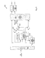
- FIG. 2 shows a block diagram of a first embodiment of a signal processing device 200 according to the invention, in which an improved difference signal d is calculated in noisy signal conditions.
- noisy signal conditions noisy signal conditions.
- noisy signal conditions noisy signal conditions.
- noisy signal conditions noisy signal conditions.
- noisy signal conditions noisy signal conditions.
- noisy signal conditions noisy signal conditions.
- noisy signal conditions noisy signal conditions.
- noisy signal conditions noisy signal conditions.
- noisy signal conditions noisy signal conditions.
- g s and g sd two gains, g s and g sd .
- d ⁇ g s ⁇ s + g sd ⁇ s d
- the above relationship includes an additional decorrelated signal component term g sd ⁇ s d .
- the parameter ⁇ is a small positive value to prevent division by zero. Therefore, effectively the parameter g s is calculated as the ratio of the complex-valued (complex-conjugate) cross correlation between the sum/difference signal pair and the power of the sum signal. This provides the least-squares fit.
- the parameter g sd is calculated as square root of the ratio of the residual signal power and the power of the sum signal.
- the sum signal s is also input to a decorrelation module 202, in which a decorrelated sum signal s d is derived that has a correlation with the sum signal s substantially close to zero and having approximately the same temporal and spectral shape as the sum signal s.
- the decorrelation module 202 can be implemented for example by means of all-pass filters or by reverberation circuitry.
- An example of a synthetic reverb is given in Jot, J.M. & Chaigne, A. (1991), Digital Delay Networks for designing Artificial Reverb, 90th Convention of the Audio Engineering Society (AES), Preprint Nr. 3030, Paris, France (reference [5] below ).
- gains g s , g sd are applied to the sum signal s and the decorrelated sum signal s d by means of first and second amplifiers 203, 204.
- the output signals g s ⁇ s , g sd ⁇ s d from the amplifiers 203, 204 are provided to a summing module 205 and added together, resulting in a synthetic difference signal d'.
- the left and right signals l' , r ' are output by the sum/difference matrix module 206 to a de-emphasis filter module 207, which derives an output stereo signal.
- the de-emphasis module 207 operates to invert a pre-emphasis that is applied during the frequency modulation process.
- the de-emphasis module may be applied to the input sum and difference signals s, d instead.
- the processing described above is preferably conducted in a number of frequency bands in order to provide the highest fidelity.
- the input multiplexed time domain signals will need to be first converted to the frequency domain, and converted back to the time domain after processing.
- Frequency and time domain conversions may be carried out by discrete Fourier transformation (DFT, a fast implementation using FFT) as for example described in Moorer, The Use of the Phase Vocoder in Computer Music Applications Journal of the Audio Engineering Society, Volume 26, Number 1/2, January/February 1978, pp 42-45 (reference [6] below), or applied to sub-band representations for example by using Quadrature Mirror Filter (QMF) banks, as for example described in P.
- DFT discrete Fourier transformation
- FFT Fast implementation using FFT
- QMF Quadrature Mirror Filter
- the signal processing device of the first embodiment may be extended by the use of noise information that can be derived from the difference signal d .
- noise information that can be derived from the difference signal d .
- a trade-off can be made between the signal attributes corresponding to a stereo image and to noisiness of the signal, which may to some extend be separable.
- FIG 3a which is a reproduction of figure 1 , illustrates a schematic representation of the Power Spectral Density (PSD) of an input FM multiplex signal.
- the input signal comprises a baseband sum signal 301 (between 0 and 15 kHz), a 19 kHz pilot tone 302 and a double sideband suppressed carrier modulated difference signal 303 (between 23 and 53 kHz).
- a noise signal 304 is also present, which tends to increase with increasing frequency.
- the difference signal 303 is effectively available twice, once in the frequency range from 23 to 38 kHz and once in the frequency range from 38 to 53 kHz.
- the signals d and n d can be obtained as illustrated in figures 3b to 3e .
- Quadrature modulation (modulation with complex-exponential) is first applied to the original input spectrum of figure 3a with a modulation frequency of 38 kHz. This results in a complex-valued signal having the spectrum indicated in figure 3b .
- This signal is then lowpass filtered to approximately 15 kHz, resulting in the signal shown in figure 3c (the bandpass filter indicated by the bandpass function 307).
- the resulting complex valued signal comprises the demodulated signal d as well as the complex-modulated signal n .
- the components d and n d can be obtained, as illustrated in figures 3d and 3e .
- the power of the difference signal d consists of the power of the difference signal plus the power of the noise estimate, under the assumption that there is zero correlation between the difference signal and the positive and negative noise components. In practice, accidental correlations may exist leading to deviations between the actual noise level of the difference signal and the noise estimate.
- the SNNR 10 ⁇ log 10 ⁇ ⁇ p d ⁇ d * ⁇ ⁇ p n d ⁇ n d *
- FIG. 4 is a block diagram representation of a signal processing device 400 according to the second embodiment, in which this SNNR is used to control the parameter estimation module 201.
- the sum and difference signals s , d are provided from an FM demultiplexer 401.
- the difference signal d and a difference noise signal estimation n d are provided to an SNNR estimation module 402.
- the SNNR is then derived from the difference signal d and the difference noise signal n d .
- the SNNR is then input to the parameter estimation module 201 to adapt the estimated parameters g s , g sd output by the parameter estimation module 201.
- the SNNR can be used to weight the gains g s and g sd such that, for an SNNR below a certain threshold, for example below 1 dB, the gains are set to 0, thereby yielding a mono signal. Between a specified range of SNNR values, for example between 1 dB and 5 dB, the estimated gains are scaled with a weight between 0 and 1.
- the above processing is preferably conducted in a time and frequency variant manner.
- the noise estimates may vary substantially from the actual noise levels for very small time and frequency tiles since the noise estimate signal n d , only provides an estimate of the actual noise signal n. Furthermore, due to poor reception conditions, such as e.g. multi-path reception effects, the noise estimate signal n d may substantially deviate from the actual noise signal. Therefore, the SNNR may be further processed to remove high frequent variations.
- the device of the second embodiment can be adapted to also allow for scaling up to transparency for low noise levels.
- a signal processing device 500 according to the third embodiment is illustrated in figure 5 .
- the original difference signal d may be employed in a further way. If the SNNR is above a certain threshold, for example 15 dB, it can be beneficial to use the original difference signal instead of the synthetic difference signal d', the derivation of which is described above for the first and second embodiments.
- a hybrid scheme may be implemented, in which, for each T/F tile, a more optimal quality can be derived depending on the actual SNNR.
- the use of a metric to control the behaviour of the parameter estimation module 201 is required.
- This metric does not necessarily need to be an SNNR estimate as detailed above, but could be a different metric that can be used to provide an estimate of signal to noise in the difference signal.
- An alternative metric may, for example, be a measure of a level of the received input signal.
- the use of SNNR is therefore a specific embodiment of a more general control metric that represents an estimate of signal to noise in the difference signal.
Landscapes
- Physics & Mathematics (AREA)
- Engineering & Computer Science (AREA)
- Acoustics & Sound (AREA)
- Signal Processing (AREA)
- Stereophonic System (AREA)
Abstract
Description
- The invention relates to multi-channel audio signal processing, in particular to a method of processing a multi-channel audio signal and to a signal processing device.
- FM radio was invented in the 1940's and extended for stereo broadcasts in the 1960's. The demodulated FM-stereo signal comprises a mono audio signal (L+R), a pilot tone of 19 kHz and a stereo difference signal (L-R) modulated on a 38 kHz sub carrier, as illustrated schematically in
figure 1 . The left and the right channels are reconstructed from themono sum signal 101 and thedifference signal 103. Although the received FM signal comprises white noise, the demodulated signal comprises a component that linearly increases with frequency (represented by noise signal 104). As themono audio signal 101 is present in a lower frequency area (below 15 kHz) it contains a substantially lower noise level than thedifference signal 103, which is transmitted at a higher frequency range in the FM signal. Known receivers therefore switch gradually from stereo to mono operation in case the the signal to noise ratio of the input signal is too low. - In stereo broadcast FM signals, the left (L) and right (R) channels are matrixed into sum (S) and difference (D) signals, i.e. S = (L+R)/2 and D = (L-R)/2. A mono FM receiver will use just the S signal. A stereo receiver will matrix the S and D signals to recover L and R: L = S+D and R = S-D. As shown in
Figure 1 , thesum signal 101 is transmitted as baseband audio in the range 30 Hz to 15 kHz (relative to the carrier frequency, corresponding to 0Hz infigure 1 ). Thedifference signal 103 is amplitude-modulated onto a 38 kHz suppressed carrier to produce a double-sideband suppressed carrier (DSBSC) signal in the range 23 to 53 kHz. A 19kHz pilot tone 102, at exactly half the 38 kHz subcarrier frequency and with a precisely defined phase relationship to it, is also generated. Thepilot tone 102 is transmitted at 8-10% of overall modulation level and used by the receiver to regenerate the 38 kHz subcarrier with the correct phase. - The final multiplex signal from the stereo generator is the sum of the
baseband audio signal 101, thepilot tone 102, and the DSBSC modulatedsubcarrier signal 103. This multiplex, along with any other subcarriers, is modulated by the FM transmitter. - In a typical FM receiver, an input signal is first subjected to a limiter in order to eliminate any amplitude modulation (AM) noise present in the signal. The output of the limiter is a square wave with a constant amplitude. The square wave is then sent through a bandpass filter with a centre frequency equal to the carrier frequency and a bandwidth equal to the bandwidth of the FM signal. The bandpass filter filters out the square wave harmonics and returns a constant-amplitude sinusoidal signal. The constant-amplitude FM signal is then differentiated. The instantaneous frequency is converted to an AM signal modulating the FM carrier function. An envelope detector extracts the amplitude, or envelope, of the input signal of interest. In this way the multiplex signal shown in
Figure 1 is retrieved. Subsequently a demultiplexer derives a sum signal s(t) and a difference signal d(t) from the multiplex signal. - As a consequence of differentiation, white noise present in the input signal becomes frequency dependent noise in the output signal. The RMS noise level is linearly proportional with the frequency. The power spectral density increases quadratically with frequency. This is described in more detail in "Information Transmission, modulation, and noise", by M. Schwartz, 3ed, chapter 5-12 (reference [9] below).
- Accordingly, the
difference signal 103, which is present around the suppressed carrier at 38 kHz is significantly more affected than themono sum signal 101 in the range up to 15 kHz. Receivers therefore tend to automatically switch to mono audio reproduction if the level of noise in a stereo signal is too high, since most of this noise will derive from thedifference signal 103. - An alternative method to that of switching off the difference signal has been proposed in
US 2006/0280310 (reference [4] below), in which a frequency selective stereo to mono blending is used based on the masking effect of the human auditory system. -
WO 2008/087577 (reference [1] below) discloses a system that also attempts to restore a reasonable stereo image while maintaining a low noise level, in which a stereo audio coding tool derived from a technique known as "Intensity Stereo" (IS) is used (disclosed in reference [3] below). According to this technique, instead of reinstating a noisy difference signal for creating a stereo signal an estimated difference signal is constructed. This estimated difference signal is created in the frequency domain by calculating a gain factor for each frequency band. A difference signal is then obtained by multiplying the frequency domain representation of the sum signal by the envelope of calculated gain parameters. - Although, the system disclosed in
WO 2008/087577 can greatly improve the overall quality compared to either the stereo signal obtained by sum/difference reconstruction or the mono fallback option, it still poses a number of disadvantages. Firstly, the technique used does not fully exploit knowledge currently available in audio coding tools. Intensity Stereo is a stereo coding tool that has been largely superseded by more powerful tools such as Parametric Stereo (disclosed in reference [2] below). Secondly, the channel conditions, and therefore the noise conditions, of the sum and difference signal will tend to vary over time. This knowledge is not fully exploited inWO 2008/087577 , which instead proposes heuristic measures to account for noisy channel conditions. Thirdly, the system does not describe how to behave in case channel conditions are either very poor or very good. - It is an object of the invention to address one or more of the above mentioned problems.
- According to a first aspect of the invention there is provided a method of processing a multi-channel audio signal, the method comprising the steps of:
- receiving an input sum signal representing a sum of a first audio signal and a second audio signal;
- receiving an input difference signal representing a difference between the first and second audio signals;
- decorrelating the sum signal to provide a decorrelated sum signal;
- calculating a first gain from a cross-correlation of the sum and difference signals and the power of the sum signal;
- calculating a second gain from a cross-correlation of the sum and difference signals and the power of the sum and difference signals;
- calculating an output difference signal from a sum of the first gain applied to the sum signal and the second gain applied to the decorrelated sum signal; and
- providing an output stereo audio signal from a combination of the output difference signal and the input sum signal.
- The first gain is optionally a complex-valued scaling factor, and may be calculated from a ratio of a complex-valued cross correlation between the sum and difference signals and the power of the sum signal.
- The second gain may be calculated as a square root of a ratio of the residual signal power and the power of the sum signal.
- The first and second gains may be set to a minimum when an estimate of signal to noise in the difference signal is below a set minimum threshold value.
- The first and second gains may be set to a maximum when an estimate of signal to noise in the difference signal is above a set maximum threshold value.
- The first and second gains may be set to a value between a minimum value and a maximum value depending on a value of an estimate of signal to noise in the difference signals being between a set minimum threshold value and a set maximum threshold value respectively.
- The estimate of signal to noise in the difference signal may be a ratio calculated from a combination of real and imaginary parts of a filtered and demodulated version of the difference signal.
- The multi-channel audio signal may be a frequency modulated signal comprising a baseband sum signal and a sideband modulated difference signal.
- According to a second aspect of the invention there is provided a signal processing device for processing a multi-channel audio signal comprising an input sum signal representing a sum of a first audio signal and a second audio signal and an input difference signal representing a differences between the first and second audio signals, the device comprising:
- a decorrelation module configured to receive the sum signal and provide a decorrelated sum signal;
- a parameter estimation module configured to calculate a first gain from a cross-correlation of the sum and difference signals and the power of the difference signal and a second gain from a cross-correlation of the sum and difference signals and the power of the sum and difference signals;
- a first amplifier configured to receive the sum signal and amplify the sum signal according to the first gain;
- a second amplifier configured to receive the decorrelated sum signal and amplify the decorrelated sum signal according to the second gain;
- a summing module configured to sum output signals from the first and second amplifiers; and
- an output stage configured to calculate an output stereo signal from a combination of the sum signal and an output signal from the summing module.
- The first gain is optionally a complex-valued scaling factor, and the parameter estimation module may be configured to calculate the first gain from a ratio of a complex-valued cross correlation between the sum and difference signals and the power of the sum signal.
- The parameter estimation module may be configured to calculate the second gain as a square root of a ratio of the residual signal power and the power of the sum signal.
- The parameter estimation module may be configured to set the first and second gains to a minimum when an estimate of signal to noise in the difference signal is below a set minimum threshold value.
- The parameter estimation module may be configure to set the first and second gains to a maximum when an estimate of signal to noise in the difference signal is above a set maximum threshold value.
- The parameter estimation module may be configured to set the first and second gains to a value between a minimum value and a maximum value depending on a value of an estimate of signal to noise in the difference signals being between a set minimum threshold value and a set maximum threshold value respectively.
- The signal processing device may comprise a noise estimation module configured to provide the estimate of signal to noise in the difference signal from a ratio calculated from a combination of real and imaginary parts of a filtered and demodulated version of the difference signal.
- The invention may be embodied as a computer program for instructing a computer to perform the method according to the first aspect. The computer program may be stored on a computer-readable medium such as a disc or memory. The computer may be a programmable microprocessor, application specific integrated circuit or a general purpose computer such as a personal computer.
- Embodiments according to the invention comprise a number of improvements that can deliver a significant reduction in noise and improvement in output sound quality, in particular with respect to the system disclosed in
WO 2008/087577 . These improvements include: - i) the use of decorrelation in a similar way to current parametric stereo coding methods;
- ii) the use of upmixing techniques that depend on the signal (or signal plus noise) to noise ratio of the difference signal, which is preferably applied in a time and frequency variant manner to allow upmixing to be applied to each Time/Frequency (T/F) tile depending on the local SNR of the T/F tile; and
- iii) the use of a hybrid scheme where, for each T/F tile, a gradual transition from an original difference signal to an estimated difference signal to using no difference signal (i.e. a sum signal alone).
- Details of exemplary embodiments according to aspects of the invention are described below with reference to the accompanying drawings, in which:
-
figure 1 is a schematic diagram of power spectral density of a frequency modulated multiplex signal in the frequency domain; -
figure 2 is a schematic block diagram of a first exemplary embodiment of a signal processing device according to the invention; -
figure 3a is a schematic representation of power spectral density of a frequency modulated multiplex signal in the frequency domain; -
figure 3b is a schematic representation of power spectral density of a complex filtered version of the signal offigure 3a ; -
figure 3c is a schematic representation of power spectral density of the signal offigure 3b after modulation to the baseband; -
figure 3d is a schematic representation of power spectral density of the real part of the signal infigure 3c ; -
figure 3e is a schematic representation of power spectral density of the imaginary part of the signal infigure 3c ; -
figure 4 is a schematic block diagram of a second exemplary embodiment of a signal processing device according to the invention; -
figure 5 is a schematic block diagram of a third exemplary embodiment of a signal processing device according to the invention. -
Figure 2 shows a block diagram of a first embodiment of asignal processing device 200 according to the invention, in which an improved difference signal d is calculated in noisy signal conditions. Noisy sum and difference signals s and d are input to aparameter estimation module 201. Based on the signal power of the sum and the difference signals and a cross-correlation of the sum and the difference signal, two gains, g s and gsd, are calculated. These gains are used to define the following transfer function from the sum signal s and a decorrelated version of the sum signal sd to an estimated prediction signal d':
- In comparison with the way the difference signal is calculated in
WO 2008/087577 , the above relationship includes an additional decorrelated signal component term gsd · sd. - The gains gs , gsd can be calculated as a function of the power of the sum and difference signals s, d and a non-normalized cross-correlation between the sum and difference signal, according to the following relationships:


- In parallel with the parameter estimation process, the sum signal s is also input to a
decorrelation module 202, in which a decorrelated sum signal sd is derived that has a correlation with the sum signal s substantially close to zero and having approximately the same temporal and spectral shape as the sum signal s. Thedecorrelation module 202 can be implemented for example by means of all-pass filters or by reverberation circuitry. An example of a synthetic reverb is given in Jot, J.M. & Chaigne, A. (1991), Digital Delay Networks for designing Artificial Reverb, 90th Convention of the Audio Engineering Society (AES), Preprint Nr. 3030, Paris, France (reference [5] below). - After decorrelation and parameter estimation, gains gs , gsd are applied to the sum signal s and the decorrelated sum signal sd by means of first and
second amplifiers amplifiers module 205 and added together, resulting in a synthetic difference signal d'. The sum signal s and the synthetic difference signal d' are then fed through a conventional sum anddifference matrix module 206, which derives left and right audio signals l', r' according to the following relationship:
- The left and right signals l', r' are output by the sum/
difference matrix module 206 to ade-emphasis filter module 207, which derives an output stereo signal. Thede-emphasis module 207 operates to invert a pre-emphasis that is applied during the frequency modulation process. In alternative embodiments, the de-emphasis module may be applied to the input sum and difference signals s, d instead. - The processing described above is preferably conducted in a number of frequency bands in order to provide the highest fidelity. In each case, the input multiplexed time domain signals will need to be first converted to the frequency domain, and converted back to the time domain after processing. Frequency and time domain conversions may be carried out by discrete Fourier transformation (DFT, a fast implementation using FFT) as for example described in Moorer, The Use of the Phase Vocoder in Computer Music Applications Journal of the Audio Engineering Society, Volume 26, Number 1/2, January/February 1978, pp 42-45 (reference [6] below), or applied to sub-band representations for example by using Quadrature Mirror Filter (QMF) banks, as for example described in P. Ekstrand, Bandwidth Extension of Audio Signals by Spectral Band Replication, Proc.1st IEEE Benelux Workshop on Model based Processing and Coding of Audio (MPCA-2002), Leuven, Belgium, November 15, 2002 (reference [7] below], or warped Linear Predictive (LP) structures as for example described in A. Härmä, M. Karjalainen, L. Savioja, V. Välimäki, U.K. Laine, and J. Huopaniemi. Frequency-warped signal processing for audio applications. J. Audio Eng. Soc., 48:1011-1031, 2000 (reference [8] below).
- According to a second embodiment, the signal processing device of the first embodiment may be extended by the use of noise information that can be derived from the difference signal d. A trade-off can be made between the signal attributes corresponding to a stereo image and to noisiness of the signal, which may to some extend be separable.
-
Figure 3a , which is a reproduction offigure 1 , illustrates a schematic representation of the Power Spectral Density (PSD) of an input FM multiplex signal. The input signal comprises a baseband sum signal 301 (between 0 and 15 kHz), a 19kHz pilot tone 302 and a double sideband suppressed carrier modulated difference signal 303 (between 23 and 53 kHz). Anoise signal 304 is also present, which tends to increase with increasing frequency. - The
difference signal 303 is effectively available twice, once in the frequency range from 23 to 38 kHz and once in the frequency range from 38 to 53 kHz. Hence, using this knowledge both the difference signal d, which consists of d=d+n, i.e., the original difference signal plus an additional noise component, is available as well as nd , where nd is an approximation of the noise signal n. The signals d and nd can be obtained as illustrated infigures 3b to 3e . Quadrature modulation (modulation with complex-exponential) is first applied to the original input spectrum offigure 3a with a modulation frequency of 38 kHz. This results in a complex-valued signal having the spectrum indicated infigure 3b . This signal is then lowpass filtered to approximately 15 kHz, resulting in the signal shown infigure 3c (the bandpass filter indicated by the bandpass function 307). The resulting complex valued signal comprises the demodulated signal d as well as the complex-modulated signal n. By taking thereal part 308 andimaginary part 309 of this signal, the components d and nd can be obtained, as illustrated infigures 3d and 3e . - As a consequence, a ratio of the signal plus noise to the noise (SNNR) of the difference signal can be estimated.
- The power of the difference signal d consists of the power of the difference signal plus the power of the noise estimate, under the assumption that there is zero correlation between the difference signal and the positive and negative noise components. In practice, accidental correlations may exist leading to deviations between the actual noise level of the difference signal and the noise estimate.
- From the difference signal and the difference noise estimate, the SNNR can be estimated according to the following relationship:

- The SNNR can be used as a means to control the parameter estimation.
Figure 4 is a block diagram representation of asignal processing device 400 according to the second embodiment, in which this SNNR is used to control theparameter estimation module 201. As with thedevice 200 of the first embodiment, the sum and difference signals s, d are provided from anFM demultiplexer 401. In addition, the difference signal d and a difference noise signal estimation nd are provided to anSNNR estimation module 402. The SNNR is then derived from the difference signal d and the difference noise signal nd . The SNNR is then input to theparameter estimation module 201 to adapt the estimated parameters gs , gsd output by theparameter estimation module 201. - Use of the SNNR as control information is applicable in situations where the difference signal is overwhelmed by noise, i.e. where the SNNR is approximately 0 dB. In such cases, the estimated parameters gs, gsd are not employed, since they would in such cases be solely based on the noise signal. For example, the SNNR can be used to weight the gains gs and gsd such that, for an SNNR below a certain threshold, for example below 1 dB, the gains are set to 0, thereby yielding a mono signal. Between a specified range of SNNR values, for example between 1 dB and 5 dB, the estimated gains are scaled with a weight between 0 and 1. For SNNR values above a specified threshold, for example 5 dB, the gains are left unaltered. These relationships can be expressed as the following relationships:


- As with the first embodiment, the above processing is preferably conducted in a time and frequency variant manner. The noise estimates may vary substantially from the actual noise levels for very small time and frequency tiles since the noise estimate signal nd , only provides an estimate of the actual noise signal n. Furthermore, due to poor reception conditions, such as e.g. multi-path reception effects, the noise estimate signal nd may substantially deviate from the actual noise signal. Therefore, the SNNR may be further processed to remove high frequent variations.
- According to a third embodiment, the device of the second embodiment can be adapted to also allow for scaling up to transparency for low noise levels. A
signal processing device 500 according to the third embodiment is illustrated infigure 5 . In addition to the scheme of the second embodiment, in which an SNNR estimation is derived, in the third embodiment the original difference signal d may be employed in a further way. If the SNNR is above a certain threshold, for example 15 dB, it can be beneficial to use the original difference signal instead of the synthetic difference signal d', the derivation of which is described above for the first and second embodiments. A hybrid scheme may be implemented, in which, for each T/F tile, a more optimal quality can be derived depending on the actual SNNR. - In this embodiment, as well as in the second embodiment, the use of a metric to control the behaviour of the
parameter estimation module 201 is required. This metric does not necessarily need to be an SNNR estimate as detailed above, but could be a different metric that can be used to provide an estimate of signal to noise in the difference signal. An alternative metric may, for example, be a measure of a level of the received input signal. The use of SNNR is therefore a specific embodiment of a more general control metric that represents an estimate of signal to noise in the difference signal. - The mix matrix used by the sum/
difference matrix module 506 for calculating the output signals l', r'then becomes the following:
- The effect of this is that the gain gd and the combined gains of gs and gsd will operate in a complementary fashion.
- Other embodiments are within the scope of the invention, as defined by the appended claims.
-
- [1]
WO 2008/087577 A1 - [2] J. Breebaart, S. van de Par, A. Kohlrausch and E. Schuijers, "Parametric Coding of Stereo Audio", in EURASIP J. Appl. Signal Process., vol 9, pp. 1305-1322 (2004).
- [3] J. Herre, K. Brandenburg, D. Lederer, "Intensity Stereo. Coding," 96th AES Convention, Amsterdam, 1994, Preprint. 3799.
- [4]
US 2006/0280310 A1 . - [5] Jot, J.M. & Chaigne, A. (1991), Digital Delay Networks for designing Artificial Reverb, 90th Convention of the Audio Engineering Society (AES), Preprint Nr. 3030, Paris, France.
- [6] Moorer, The Use of the Phase Vocoder in Computer Music Applications Journal of the Audio Engineering Society, Volume 26, Number 1/2, January/February 1978, pp 42-45.
- [7] P. Ekstrand, Bandwidth Extension of Audio Signals by Spectral Band Replication, Proc.1st IEEE Benelux Workshop on Model based Processing and Coding of Audio (MPCA-2002), Leuven, Belgium, November 15, 2002.
- [8] A. Härmä, M. Karjalainen, L. Savioja, V. Välimäki, U.K. Laine, and J. Huopaniemi. Frequency-warped signal processing for audio applications. J. Audio Eng. Soc., 48:1011-1031, 2000.
- [9] M. Schwartz, "Information Transmission, modulation, and noise", 3ed, chapter 5-12
Claims (13)
- A method of processing a multi-channel audio signal, the method comprising the steps of:receiving an input sum signal (s) representing a sum of a first audio signal and a second audio signal;receiving an input difference signal (d) representing a difference between the first and second audio signals;decorrelating the sum signal to provide a decorrelated sum signal (sd);calculating a first gain (gs) from a cross-correlation of the sum and difference signals (s,d) and the power of the sum signal;calculating a second gain (gsd) from a cross-correlation of the sum and difference signals (s,d) and the power of the sum and difference signals;calculating an output difference signal (d') from a sum of the first gain (gs) applied to the sum signal (s) and the second gain (gsd) applied to the decorrelated sum signal (sd); andproviding an output stereo audio signal (l,r) from a combination of the output difference signal (d') and the input sum signal (s).
- The method of claim 1 wherein the first gain is a complex-valued scaling factor.
- The method of claim 1 or claim 2 wherein the first gain (gs) is calculated from a ratio of a complex-valued cross correlation between the sum and difference signals and the power of the sum signal.
- The method of any preceding claim wherein the second gain (gsd) is calculated as a square root of a ratio of the residual signal power and the power of the sum signal.
- The method of any preceding claim wherein the first and second gains are set to a minimum when an estimate of signal to noise in the difference signal is below a set minimum threshold value.
- The method of any preceding claim wherein the first and second gains are set to a maximum when an estimate of signal to noise in the difference signal is above a set maximum threshold value.
- The method of any preceding claim wherein the first and second gains are set to a value between a minimum value and a maximum value depending on a value of an estimate of signal to noise in the difference signal being between a set minimum threshold value and a set maximum threshold value respectively.
- The method of any preceding claim wherein the difference signal is provided as the output difference signal when a value of an estimate of signal to noise in the difference signal is above a set maximum threshold value.
- The method of any one of claims 5 to 8 where the estimate of signal to noise in the difference signal is a ratio calculated from a combination of real and imaginary parts of a filtered and demodulated version of the difference signal.
- The method of any preceding claim wherein the multi-channel audio signal is a frequency modulated signal comprising a baseband sum signal and a sideband modulated difference signal.
- A signal processing device (200) for processing a multi-channel audio signal comprising an input sum signal (s) representing a sum of a first audio signal and a second audio signal and an input difference signal (d) representing a difference between the first and second audio signals, the device (200) comprising:a decorrelation module (202) configured to receive the sum signal (s) and provide a decorrelated sum signal (sd);a parameter estimation module (201) configured to calculate a first gain (gs) from a cross-correlation of the sum and difference signals (s,d) and the power of the difference signal and a second gain (gsd) from a cross-correlation of the sum and difference signals (s,d) and the power of the sum and difference signals;a first amplifier (203) configured to receive the sum signal (s) and amplify the sum signal according to the first gain (gs);a second amplifier (204) configured to receive the decorrelated sum signal (sd) and amplify the decorrelated sum signal according to the second gain (gsd);a summing module (205) configured to sum output signals from the first and second amplifiers (203, 204) to provide an output difference signal (d'); andan output stage (206, 207) configured to calculate an output stereo signal (l,r) from a combination of the sum signal (s) and the output difference signal (d') from the summing module.
- A computer program for instructing a computer to perform the method according to any one of claims 1 to 10.
- A computer program product comprising a computer-readable medium on which is stored the computer program of claim 12.
Priority Applications (3)
| Application Number | Priority Date | Filing Date | Title |
|---|---|---|---|
| EP10250574.0A EP2369861B1 (en) | 2010-03-25 | 2010-03-25 | Multi-channel audio signal processing |
| CN201110076978.2A CN102201823B (en) | 2010-03-25 | 2011-03-23 | Multi-channel audio signal processing |
| US13/070,613 US8638948B2 (en) | 2010-03-25 | 2011-03-24 | Multi-channel audio signal processing |
Applications Claiming Priority (1)
| Application Number | Priority Date | Filing Date | Title |
|---|---|---|---|
| EP10250574.0A EP2369861B1 (en) | 2010-03-25 | 2010-03-25 | Multi-channel audio signal processing |
Publications (2)
| Publication Number | Publication Date |
|---|---|
| EP2369861A1 true EP2369861A1 (en) | 2011-09-28 |
| EP2369861B1 EP2369861B1 (en) | 2016-07-27 |
Family
ID=43332678
Family Applications (1)
| Application Number | Title | Priority Date | Filing Date |
|---|---|---|---|
| EP10250574.0A Not-in-force EP2369861B1 (en) | 2010-03-25 | 2010-03-25 | Multi-channel audio signal processing |
Country Status (3)
| Country | Link |
|---|---|
| US (1) | US8638948B2 (en) |
| EP (1) | EP2369861B1 (en) |
| CN (1) | CN102201823B (en) |
Families Citing this family (9)
| Publication number | Priority date | Publication date | Assignee | Title |
|---|---|---|---|---|
| KR100889478B1 (en) * | 2007-11-23 | 2009-03-19 | 정원섭 | Audio device with multiple sound images |
| UA107771C2 (en) * | 2011-09-29 | 2015-02-10 | Dolby Int Ab | Prediction-based fm stereo radio noise reduction |
| EP2615739B1 (en) * | 2012-01-16 | 2015-06-17 | Nxp B.V. | Processor for an FM signal receiver and processing method |
| KR102155555B1 (en) * | 2013-06-25 | 2020-09-14 | 삼성전자주식회사 | Method for providing a hearing aid compatibility and an electronic device thereof |
| EP2830054A1 (en) | 2013-07-22 | 2015-01-28 | Fraunhofer Gesellschaft zur Förderung der angewandten Forschung e.V. | Audio encoder, audio decoder and related methods using two-channel processing within an intelligent gap filling framework |
| WO2016142002A1 (en) | 2015-03-09 | 2016-09-15 | Fraunhofer-Gesellschaft Zur Foerderung Der Angewandten Forschung E.V. | Audio encoder, audio decoder, method for encoding an audio signal and method for decoding an encoded audio signal |
| WO2020030795A1 (en) * | 2018-08-10 | 2020-02-13 | Telefonaktiebolaget Lm Ericsson (Publ) | Multi-source quasi collocation of reference signals |
| CN110246508B (en) * | 2019-06-14 | 2021-08-31 | 腾讯音乐娱乐科技(深圳)有限公司 | Signal modulation method, device and storage medium |
| US12019902B2 (en) * | 2021-08-03 | 2024-06-25 | Data Culpa, Inc. | Data lineage in a data pipeline |
Citations (3)
| Publication number | Priority date | Publication date | Assignee | Title |
|---|---|---|---|---|
| EP1206043A1 (en) * | 2000-11-08 | 2002-05-15 | Sony International (Europe) GmbH | Noise reduction in a stereo receiver |
| WO2003090206A1 (en) * | 2002-04-22 | 2003-10-30 | Koninklijke Philips Electronics N.V. | Signal synthesizing |
| WO2008087577A1 (en) | 2007-01-17 | 2008-07-24 | Nxp B.V. | Receiver for a multi-channel audio signal, method for processing a multi-channel audio signal and signal processing device |
Family Cites Families (17)
| Publication number | Priority date | Publication date | Assignee | Title |
|---|---|---|---|---|
| US3811011A (en) * | 1969-07-08 | 1974-05-14 | Itek Corp | Multiple image registration system |
| TW384434B (en) * | 1997-03-31 | 2000-03-11 | Sony Corp | Encoding method, device therefor, decoding method, device therefor and recording medium |
| JP3657828B2 (en) * | 1999-09-22 | 2005-06-08 | パイオニア株式会社 | Tracking control device |
| KR100423724B1 (en) * | 2001-06-09 | 2004-03-22 | 주식회사 팬택앤큐리텔 | Apparatus and method for processing data using CQPSK of wireless communication system |
| JP2003084790A (en) * | 2001-09-17 | 2003-03-19 | Matsushita Electric Ind Co Ltd | Dialogue component emphasis device |
| ATE402468T1 (en) * | 2004-03-17 | 2008-08-15 | Harman Becker Automotive Sys | SOUND TUNING DEVICE, USE THEREOF AND SOUND TUNING METHOD |
| BRPI0509113B8 (en) * | 2004-04-05 | 2018-10-30 | Koninklijke Philips Nv | multichannel encoder, method for encoding input signals, encoded data content, data bearer, and operable decoder for decoding encoded output data |
| JP4759252B2 (en) * | 2004-11-22 | 2011-08-31 | ルネサスエレクトロニクス株式会社 | Power control circuit, semiconductor device using the same, and transmission / reception circuit |
| US7573912B2 (en) * | 2005-02-22 | 2009-08-11 | Fraunhofer-Gesellschaft Zur Foerderung Der Angewandten Forschunng E.V. | Near-transparent or transparent multi-channel encoder/decoder scheme |
| KR100707184B1 (en) * | 2005-03-10 | 2007-04-13 | 삼성전자주식회사 | Audio encoding and decoding apparatus, method and recording medium |
| US7961890B2 (en) * | 2005-04-15 | 2011-06-14 | Fraunhofer-Gesellschaft Zur Foerderung Der Angewandten Forschung, E.V. | Multi-channel hierarchical audio coding with compact side information |
| EP1999997B1 (en) * | 2006-03-28 | 2011-04-13 | Fraunhofer-Gesellschaft zur Förderung der angewandten Forschung e.V. | Enhanced method for signal shaping in multi-channel audio reconstruction |
| KR100771854B1 (en) * | 2006-08-22 | 2007-11-01 | 삼성전자주식회사 | Low noise DC-DC converters to compensate for variations in supply voltage |
| AU2007318506B2 (en) * | 2006-11-10 | 2012-03-08 | Iii Holdings 12, Llc | Parameter decoding device, parameter encoding device, and parameter decoding method |
| JP5554065B2 (en) * | 2007-02-06 | 2014-07-23 | コーニンクレッカ フィリップス エヌ ヴェ | Parametric stereo decoder with reduced complexity |
| JP5366104B2 (en) * | 2008-06-26 | 2013-12-11 | オランジュ | Spatial synthesis of multi-channel audio signals |
| KR101428487B1 (en) * | 2008-07-11 | 2014-08-08 | 삼성전자주식회사 | Multi-channel encoding and decoding method and apparatus |
-
2010
- 2010-03-25 EP EP10250574.0A patent/EP2369861B1/en not_active Not-in-force
-
2011
- 2011-03-23 CN CN201110076978.2A patent/CN102201823B/en not_active Expired - Fee Related
- 2011-03-24 US US13/070,613 patent/US8638948B2/en not_active Expired - Fee Related
Patent Citations (4)
| Publication number | Priority date | Publication date | Assignee | Title |
|---|---|---|---|---|
| EP1206043A1 (en) * | 2000-11-08 | 2002-05-15 | Sony International (Europe) GmbH | Noise reduction in a stereo receiver |
| US20060280310A1 (en) | 2000-11-08 | 2006-12-14 | Sony Deutschland Gmbh | Noise reduction in a stereo receiver |
| WO2003090206A1 (en) * | 2002-04-22 | 2003-10-30 | Koninklijke Philips Electronics N.V. | Signal synthesizing |
| WO2008087577A1 (en) | 2007-01-17 | 2008-07-24 | Nxp B.V. | Receiver for a multi-channel audio signal, method for processing a multi-channel audio signal and signal processing device |
Non-Patent Citations (7)
| Title |
|---|
| A. HÄRMÄ; M. KARJALAINEN; L. SAVIOJA; V. VÄLIMÄKI; U.K. LAINE; J. HUOPANIEMI: "Frequency-warped signal processing for audio applications", J. AUDIO ENG. SOC., vol. 48, 2000, pages 1011 - 1031 |
| J. BREEBAART; S. VAN DE PAR; A. KOHLRAUSCH; E. SCHUIJERS: "Parametric Coding of Stereo Audio", EURASIP J. APPL SIGNAL PROCESS., vol. 9, 2004, pages 1305 - 1322 |
| J. HERRE; K. BRANDENBURG; D. LEDERER: "Intensity Stereo. Coding", 96TH AES CONVENTION, AMSTERDAM, 1994 |
| JOT, J.M.; CHAIGNE, A.: "Digital Delay Networks for designing Artificial Reverb, 90th Convention of the Audio Engineering Society (AES)", PREPRINT NR. 3030, 1991 |
| MOORER, THE USE OF THE PHASE VOCODER IN COMPUTER MUSIC APPLICATIONS JOURNAL OF THE AUDIO ENGINEERING SOCIETY, vol. 26, no. 1-2, January 1978 (1978-01-01), pages 42 - 45 |
| P. EKSTRAND, BANDWIDTH EXTENSION OF AUDIO SIGNALS BY SPECTRAL BAND REPLICATION, PROC.1ST IEEE BENELUX WORKSHOP ON MODEL BASED PROCESSING AND CODING OF AUDIO (MPCA-2002), 15 November 2002 (2002-11-15) |
| P. EKSTRAND: "Bandwidth Extension of Audio Signals by Spectral Band Replication", PROC.1ST IEEE BENELUX WORKSHOP ON MODEL BASED PROCESSING AND CODING OF AUDIO (MPCA-2002), LEUVEN, BELGIUM, 15 November 2002 (2002-11-15) |
Also Published As
| Publication number | Publication date |
|---|---|
| CN102201823A (en) | 2011-09-28 |
| EP2369861B1 (en) | 2016-07-27 |
| CN102201823B (en) | 2013-11-06 |
| US20110235809A1 (en) | 2011-09-29 |
| US8638948B2 (en) | 2014-01-28 |
Similar Documents
| Publication | Publication Date | Title |
|---|---|---|
| EP2369861B1 (en) | Multi-channel audio signal processing | |
| EP2162882B1 (en) | Hybrid derivation of surround sound audio channels by controllably combining ambience and matrix-decoded signal components | |
| EP2612322B1 (en) | Method and device for decoding a multichannel audio signal | |
| RU2365063C2 (en) | Method of sound channels mixing with use of correlated output data | |
| US7894611B2 (en) | Spatial disassembly processor | |
| US20100111330A1 (en) | Audio mixing using magnitude equalization | |
| US20030235317A1 (en) | Equalization for audio mixing | |
| US20070223740A1 (en) | Audio spatial environment engine using a single fine structure | |
| EP2941770B1 (en) | Method for determining a stereo signal | |
| KR101575185B1 (en) | Method for generating a downward sound format | |
| Romoli et al. | A combined approach for channel decorrelation in stereo acoustic echo cancellation exploiting time-varying frequency shifting | |
| CN102903363B (en) | Stereo decoding | |
| CN103023849B (en) | Psychoacoustic-model-based data transmission method of IBOC (in-band on-channel) system | |
| WO2008087577A1 (en) | Receiver for a multi-channel audio signal, method for processing a multi-channel audio signal and signal processing device | |
| US7313240B2 (en) | Noise reduction in a stereo receiver comprising an expander | |
| US8064858B1 (en) | Digital carrier-recovery scheme for FM stereo detection | |
| US10003422B2 (en) | Method for processing an FM stereo signal | |
| EP2615739B1 (en) | Processor for an FM signal receiver and processing method | |
| JPH0419862Y2 (en) | ||
| JPH06224788A (en) | Voice signal processor by band division | |
| Kim | Adaptive channel re-mixing algorithm for intended emphasis on the surround sound | |
| JP2014206559A (en) | Receiving device and program | |
| JPH05304505A (en) | Fm stereo receiver |
Legal Events
| Date | Code | Title | Description |
|---|---|---|---|
| PUAI | Public reference made under article 153(3) epc to a published international application that has entered the european phase |
Free format text: ORIGINAL CODE: 0009012 |
|
| AK | Designated contracting states |
Kind code of ref document: A1 Designated state(s): AT BE BG CH CY CZ DE DK EE ES FI FR GB GR HR HU IE IS IT LI LT LU LV MC MK MT NL NO PL PT RO SE SI SK SM TR |
|
| AX | Request for extension of the european patent |
Extension state: AL BA ME RS |
|
| 17P | Request for examination filed |
Effective date: 20120328 |
|
| GRAP | Despatch of communication of intention to grant a patent |
Free format text: ORIGINAL CODE: EPIDOSNIGR1 |
|
| RIC1 | Information provided on ipc code assigned before grant |
Ipc: H04B 1/16 20060101ALN20150828BHEP Ipc: H04S 1/00 20060101AFI20150828BHEP |
|
| INTG | Intention to grant announced |
Effective date: 20150907 |
|
| RIC1 | Information provided on ipc code assigned before grant |
Ipc: H04B 1/16 20060101ALN20150828BHEP Ipc: H04S 1/00 20060101AFI20150828BHEP |
|
| RIC1 | Information provided on ipc code assigned before grant |
Ipc: H04B 1/16 20060101ALN20160119BHEP Ipc: H04S 1/00 20060101AFI20160119BHEP |
|
| INTG | Intention to grant announced |
Effective date: 20160215 |
|
| RIC1 | Information provided on ipc code assigned before grant |
Ipc: H04S 1/00 20060101AFI20160205BHEP Ipc: H04B 1/16 20060101ALN20160205BHEP |
|
| GRAS | Grant fee paid |
Free format text: ORIGINAL CODE: EPIDOSNIGR3 |
|
| GRAA | (expected) grant |
Free format text: ORIGINAL CODE: 0009210 |
|
| AK | Designated contracting states |
Kind code of ref document: B1 Designated state(s): AT BE BG CH CY CZ DE DK EE ES FI FR GB GR HR HU IE IS IT LI LT LU LV MC MK MT NL NO PL PT RO SE SI SK SM TR |
|
| REG | Reference to a national code |
Ref country code: GB Ref legal event code: FG4D |
|
| REG | Reference to a national code |
Ref country code: CH Ref legal event code: EP |
|
| REG | Reference to a national code |
Ref country code: AT Ref legal event code: REF Ref document number: 816655 Country of ref document: AT Kind code of ref document: T Effective date: 20160815 |
|
| REG | Reference to a national code |
Ref country code: IE Ref legal event code: FG4D |
|
| REG | Reference to a national code |
Ref country code: DE Ref legal event code: R096 Ref document number: 602010035005 Country of ref document: DE |
|
| REG | Reference to a national code |
Ref country code: LT Ref legal event code: MG4D |
|
| REG | Reference to a national code |
Ref country code: NL Ref legal event code: MP Effective date: 20160727 |
|
| REG | Reference to a national code |
Ref country code: AT Ref legal event code: MK05 Ref document number: 816655 Country of ref document: AT Kind code of ref document: T Effective date: 20160727 |
|
| PG25 | Lapsed in a contracting state [announced via postgrant information from national office to epo] |
Ref country code: NL Free format text: LAPSE BECAUSE OF FAILURE TO SUBMIT A TRANSLATION OF THE DESCRIPTION OR TO PAY THE FEE WITHIN THE PRESCRIBED TIME-LIMIT Effective date: 20160727 Ref country code: NO Free format text: LAPSE BECAUSE OF FAILURE TO SUBMIT A TRANSLATION OF THE DESCRIPTION OR TO PAY THE FEE WITHIN THE PRESCRIBED TIME-LIMIT Effective date: 20161027 Ref country code: HR Free format text: LAPSE BECAUSE OF FAILURE TO SUBMIT A TRANSLATION OF THE DESCRIPTION OR TO PAY THE FEE WITHIN THE PRESCRIBED TIME-LIMIT Effective date: 20160727 Ref country code: FI Free format text: LAPSE BECAUSE OF FAILURE TO SUBMIT A TRANSLATION OF THE DESCRIPTION OR TO PAY THE FEE WITHIN THE PRESCRIBED TIME-LIMIT Effective date: 20160727 Ref country code: LT Free format text: LAPSE BECAUSE OF FAILURE TO SUBMIT A TRANSLATION OF THE DESCRIPTION OR TO PAY THE FEE WITHIN THE PRESCRIBED TIME-LIMIT Effective date: 20160727 Ref country code: IT Free format text: LAPSE BECAUSE OF FAILURE TO SUBMIT A TRANSLATION OF THE DESCRIPTION OR TO PAY THE FEE WITHIN THE PRESCRIBED TIME-LIMIT Effective date: 20160727 Ref country code: IS Free format text: LAPSE BECAUSE OF FAILURE TO SUBMIT A TRANSLATION OF THE DESCRIPTION OR TO PAY THE FEE WITHIN THE PRESCRIBED TIME-LIMIT Effective date: 20161127 |
|
| REG | Reference to a national code |
Ref country code: FR Ref legal event code: PLFP Year of fee payment: 8 |
|
| PG25 | Lapsed in a contracting state [announced via postgrant information from national office to epo] |
Ref country code: PT Free format text: LAPSE BECAUSE OF FAILURE TO SUBMIT A TRANSLATION OF THE DESCRIPTION OR TO PAY THE FEE WITHIN THE PRESCRIBED TIME-LIMIT Effective date: 20161128 Ref country code: PL Free format text: LAPSE BECAUSE OF FAILURE TO SUBMIT A TRANSLATION OF THE DESCRIPTION OR TO PAY THE FEE WITHIN THE PRESCRIBED TIME-LIMIT Effective date: 20160727 Ref country code: BE Free format text: LAPSE BECAUSE OF FAILURE TO SUBMIT A TRANSLATION OF THE DESCRIPTION OR TO PAY THE FEE WITHIN THE PRESCRIBED TIME-LIMIT Effective date: 20160727 Ref country code: AT Free format text: LAPSE BECAUSE OF FAILURE TO SUBMIT A TRANSLATION OF THE DESCRIPTION OR TO PAY THE FEE WITHIN THE PRESCRIBED TIME-LIMIT Effective date: 20160727 Ref country code: LV Free format text: LAPSE BECAUSE OF FAILURE TO SUBMIT A TRANSLATION OF THE DESCRIPTION OR TO PAY THE FEE WITHIN THE PRESCRIBED TIME-LIMIT Effective date: 20160727 Ref country code: ES Free format text: LAPSE BECAUSE OF FAILURE TO SUBMIT A TRANSLATION OF THE DESCRIPTION OR TO PAY THE FEE WITHIN THE PRESCRIBED TIME-LIMIT Effective date: 20160727 Ref country code: SE Free format text: LAPSE BECAUSE OF FAILURE TO SUBMIT A TRANSLATION OF THE DESCRIPTION OR TO PAY THE FEE WITHIN THE PRESCRIBED TIME-LIMIT Effective date: 20160727 Ref country code: GR Free format text: LAPSE BECAUSE OF FAILURE TO SUBMIT A TRANSLATION OF THE DESCRIPTION OR TO PAY THE FEE WITHIN THE PRESCRIBED TIME-LIMIT Effective date: 20161028 |
|
| PG25 | Lapsed in a contracting state [announced via postgrant information from national office to epo] |
Ref country code: EE Free format text: LAPSE BECAUSE OF FAILURE TO SUBMIT A TRANSLATION OF THE DESCRIPTION OR TO PAY THE FEE WITHIN THE PRESCRIBED TIME-LIMIT Effective date: 20160727 Ref country code: RO Free format text: LAPSE BECAUSE OF FAILURE TO SUBMIT A TRANSLATION OF THE DESCRIPTION OR TO PAY THE FEE WITHIN THE PRESCRIBED TIME-LIMIT Effective date: 20160727 |
|
| REG | Reference to a national code |
Ref country code: DE Ref legal event code: R097 Ref document number: 602010035005 Country of ref document: DE |
|
| PG25 | Lapsed in a contracting state [announced via postgrant information from national office to epo] |
Ref country code: SM Free format text: LAPSE BECAUSE OF FAILURE TO SUBMIT A TRANSLATION OF THE DESCRIPTION OR TO PAY THE FEE WITHIN THE PRESCRIBED TIME-LIMIT Effective date: 20160727 Ref country code: DK Free format text: LAPSE BECAUSE OF FAILURE TO SUBMIT A TRANSLATION OF THE DESCRIPTION OR TO PAY THE FEE WITHIN THE PRESCRIBED TIME-LIMIT Effective date: 20160727 Ref country code: CZ Free format text: LAPSE BECAUSE OF FAILURE TO SUBMIT A TRANSLATION OF THE DESCRIPTION OR TO PAY THE FEE WITHIN THE PRESCRIBED TIME-LIMIT Effective date: 20160727 Ref country code: SK Free format text: LAPSE BECAUSE OF FAILURE TO SUBMIT A TRANSLATION OF THE DESCRIPTION OR TO PAY THE FEE WITHIN THE PRESCRIBED TIME-LIMIT Effective date: 20160727 Ref country code: BG Free format text: LAPSE BECAUSE OF FAILURE TO SUBMIT A TRANSLATION OF THE DESCRIPTION OR TO PAY THE FEE WITHIN THE PRESCRIBED TIME-LIMIT Effective date: 20161027 |
|
| PLBE | No opposition filed within time limit |
Free format text: ORIGINAL CODE: 0009261 |
|
| STAA | Information on the status of an ep patent application or granted ep patent |
Free format text: STATUS: NO OPPOSITION FILED WITHIN TIME LIMIT |
|
| 26N | No opposition filed |
Effective date: 20170502 |
|
| PG25 | Lapsed in a contracting state [announced via postgrant information from national office to epo] |
Ref country code: SI Free format text: LAPSE BECAUSE OF FAILURE TO SUBMIT A TRANSLATION OF THE DESCRIPTION OR TO PAY THE FEE WITHIN THE PRESCRIBED TIME-LIMIT Effective date: 20160727 |
|
| REG | Reference to a national code |
Ref country code: CH Ref legal event code: PL |
|
| GBPC | Gb: european patent ceased through non-payment of renewal fee |
Effective date: 20170325 |
|
| PG25 | Lapsed in a contracting state [announced via postgrant information from national office to epo] |
Ref country code: MC Free format text: LAPSE BECAUSE OF FAILURE TO SUBMIT A TRANSLATION OF THE DESCRIPTION OR TO PAY THE FEE WITHIN THE PRESCRIBED TIME-LIMIT Effective date: 20160727 |
|
| REG | Reference to a national code |
Ref country code: IE Ref legal event code: MM4A |
|
| PG25 | Lapsed in a contracting state [announced via postgrant information from national office to epo] |
Ref country code: LU Free format text: LAPSE BECAUSE OF NON-PAYMENT OF DUE FEES Effective date: 20170325 |
|
| REG | Reference to a national code |
Ref country code: FR Ref legal event code: PLFP Year of fee payment: 9 |
|
| PG25 | Lapsed in a contracting state [announced via postgrant information from national office to epo] |
Ref country code: LI Free format text: LAPSE BECAUSE OF NON-PAYMENT OF DUE FEES Effective date: 20170331 Ref country code: GB Free format text: LAPSE BECAUSE OF NON-PAYMENT OF DUE FEES Effective date: 20170325 Ref country code: IE Free format text: LAPSE BECAUSE OF NON-PAYMENT OF DUE FEES Effective date: 20170325 Ref country code: CH Free format text: LAPSE BECAUSE OF NON-PAYMENT OF DUE FEES Effective date: 20170331 |
|
| PG25 | Lapsed in a contracting state [announced via postgrant information from national office to epo] |
Ref country code: MT Free format text: LAPSE BECAUSE OF NON-PAYMENT OF DUE FEES Effective date: 20170325 |
|
| PG25 | Lapsed in a contracting state [announced via postgrant information from national office to epo] |
Ref country code: HU Free format text: LAPSE BECAUSE OF FAILURE TO SUBMIT A TRANSLATION OF THE DESCRIPTION OR TO PAY THE FEE WITHIN THE PRESCRIBED TIME-LIMIT; INVALID AB INITIO Effective date: 20100325 |
|
| PG25 | Lapsed in a contracting state [announced via postgrant information from national office to epo] |
Ref country code: CY Free format text: LAPSE BECAUSE OF NON-PAYMENT OF DUE FEES Effective date: 20160727 |
|
| PG25 | Lapsed in a contracting state [announced via postgrant information from national office to epo] |
Ref country code: MK Free format text: LAPSE BECAUSE OF FAILURE TO SUBMIT A TRANSLATION OF THE DESCRIPTION OR TO PAY THE FEE WITHIN THE PRESCRIBED TIME-LIMIT Effective date: 20160727 |
|
| PG25 | Lapsed in a contracting state [announced via postgrant information from national office to epo] |
Ref country code: TR Free format text: LAPSE BECAUSE OF FAILURE TO SUBMIT A TRANSLATION OF THE DESCRIPTION OR TO PAY THE FEE WITHIN THE PRESCRIBED TIME-LIMIT Effective date: 20160727 |
|
| PGFP | Annual fee paid to national office [announced via postgrant information from national office to epo] |
Ref country code: FR Payment date: 20210219 Year of fee payment: 12 |
|
| PGFP | Annual fee paid to national office [announced via postgrant information from national office to epo] |
Ref country code: DE Payment date: 20210217 Year of fee payment: 12 |
|
| REG | Reference to a national code |
Ref country code: DE Ref legal event code: R119 Ref document number: 602010035005 Country of ref document: DE |
|
| PG25 | Lapsed in a contracting state [announced via postgrant information from national office to epo] |
Ref country code: FR Free format text: LAPSE BECAUSE OF NON-PAYMENT OF DUE FEES Effective date: 20220331 Ref country code: DE Free format text: LAPSE BECAUSE OF NON-PAYMENT OF DUE FEES Effective date: 20221001 |