EP2369801B1 - Data receiver with improved response to long and short term data signal fading - Google Patents
Data receiver with improved response to long and short term data signal fading Download PDFInfo
- Publication number
- EP2369801B1 EP2369801B1 EP11159476.8A EP11159476A EP2369801B1 EP 2369801 B1 EP2369801 B1 EP 2369801B1 EP 11159476 A EP11159476 A EP 11159476A EP 2369801 B1 EP2369801 B1 EP 2369801B1
- Authority
- EP
- European Patent Office
- Prior art keywords
- data signal
- delay
- receiver
- decision metric
- phase
- Prior art date
- Legal status (The legal status is an assumption and is not a legal conclusion. Google has not performed a legal analysis and makes no representation as to the accuracy of the status listed.)
- Active
Links
- 238000005562 fading Methods 0.000 title claims description 16
- 230000001427 coherent effect Effects 0.000 claims description 26
- 238000001514 detection method Methods 0.000 claims description 25
- 238000009826 distribution Methods 0.000 claims description 21
- 238000000034 method Methods 0.000 claims description 12
- 238000007493 shaping process Methods 0.000 claims description 11
- 230000006735 deficit Effects 0.000 claims description 9
- 238000012545 processing Methods 0.000 claims description 4
- 238000013461 design Methods 0.000 description 34
- 230000001934 delay Effects 0.000 description 20
- 230000005540 biological transmission Effects 0.000 description 7
- 238000004891 communication Methods 0.000 description 4
- 238000007476 Maximum Likelihood Methods 0.000 description 3
- 239000000654 additive Substances 0.000 description 2
- 230000000996 additive effect Effects 0.000 description 2
- 230000015556 catabolic process Effects 0.000 description 2
- 238000006731 degradation reaction Methods 0.000 description 2
- 230000000694 effects Effects 0.000 description 2
- 101100366000 Caenorhabditis elegans snr-1 gene Proteins 0.000 description 1
- 230000006978 adaptation Effects 0.000 description 1
- 230000003044 adaptive effect Effects 0.000 description 1
- 238000004458 analytical method Methods 0.000 description 1
- 238000013459 approach Methods 0.000 description 1
- 230000015572 biosynthetic process Effects 0.000 description 1
- 238000012512 characterization method Methods 0.000 description 1
- 239000002131 composite material Substances 0.000 description 1
- 230000001143 conditioned effect Effects 0.000 description 1
- 230000000593 degrading effect Effects 0.000 description 1
- 230000001419 dependent effect Effects 0.000 description 1
- 238000009795 derivation Methods 0.000 description 1
- 238000012938 design process Methods 0.000 description 1
- 230000006866 deterioration Effects 0.000 description 1
- 238000011161 development Methods 0.000 description 1
- 230000018109 developmental process Effects 0.000 description 1
- 230000007613 environmental effect Effects 0.000 description 1
- 230000010354 integration Effects 0.000 description 1
- 230000007774 longterm Effects 0.000 description 1
- 238000013507 mapping Methods 0.000 description 1
- 230000010363 phase shift Effects 0.000 description 1
- 230000000644 propagated effect Effects 0.000 description 1
- 230000003595 spectral effect Effects 0.000 description 1
- 230000001360 synchronised effect Effects 0.000 description 1
- 238000003786 synthesis reaction Methods 0.000 description 1
Images

Classifications
-
- H—ELECTRICITY
- H04—ELECTRIC COMMUNICATION TECHNIQUE
- H04L—TRANSMISSION OF DIGITAL INFORMATION, e.g. TELEGRAPHIC COMMUNICATION
- H04L25/00—Baseband systems
- H04L25/02—Details ; arrangements for supplying electrical power along data transmission lines
- H04L25/03—Shaping networks in transmitter or receiver, e.g. adaptive shaping networks
- H04L25/03006—Arrangements for removing intersymbol interference
- H04L25/03178—Arrangements involving sequence estimation techniques
-
- H—ELECTRICITY
- H04—ELECTRIC COMMUNICATION TECHNIQUE
- H04L—TRANSMISSION OF DIGITAL INFORMATION, e.g. TELEGRAPHIC COMMUNICATION
- H04L25/00—Baseband systems
- H04L25/02—Details ; arrangements for supplying electrical power along data transmission lines
- H04L25/06—DC level restoring means; Bias distortion correction ; Decision circuits providing symbol by symbol detection
- H04L25/067—DC level restoring means; Bias distortion correction ; Decision circuits providing symbol by symbol detection providing soft decisions, i.e. decisions together with an estimate of reliability
Definitions
- the invention to which this application relates is a broadcast data receiver apparatus which is provided in a form so as to have an improved response to long and short term fading of the data channels.
- Broadcast signals which are transmitted are typically distorted by atmospheric and environmental impairments, thereby degrading the quality of the signal which is subsequently received.
- one form of deterioration is fading which is typically caused by physical phenomena such as reflection, diffraction and scattering.
- the effect of these phenomena is either rich or poor. This is the case in the occurrence of multipath and shadowing fading, respectively.
- Suzuki statistical distribution Another known distribution known as the Suzuki statistical distribution has the advantage that it is a composite Rayleigh/Lognormal distribution. As a consequence, it is capable of describing at once both the multipath and the shadowing of communication signals which occur simultaneously during wireless propagation.
- PDF probability density function
- An explicit solution to this integral is not known in the prior art and thus it has not been possible to implement a receiver for a digital data system which is operable over such a fading channel.
- the document in the name of Coulson AJ et al entitled "Improving fading distribution for mobile radio" Proceedings of IEE, vol.145, no.3, 16 June 1998, pages 197-202 discloses the use of Suzuki distribution in data signal decoding.
- An existing method of compensating for shadowing is by providing the receiver with empirical data, i.e. actual data, relating to the geographical area in which the receiver is to be used.
- empirical data i.e. actual data
- the data is not always specific enough to the receiver location, and if the receiver is moved to a new location, new empirical data has to be obtained.
- An aim of the present invention is to provide a receiver which can characterise accurately the signal degradation caused by the presence of multipath fading and shadowing. Another aim is to provide a method whereby the characterisation of the signal degradation can be accurately determined.
- the receiver can be optimised in a number of conditions such that the requirement for empirically modelling the channel before deploying a new network is removed.
- the receiver has improved performance over fading channels and is adaptive to the location of the receiver.
- the design or configuration of the receiving apparatus include details of coherent detection as well as non-coherent detection.
- the designs include details of the possible modulation schemes, typically M-PSK, M-QAM, ASK/PAM, FSK, MSK and OFDM.
- the designs include a plurality of shaping pulses, typically square, sinusoidal and cosine.
- the broadcast receiver characterises signal impairment optimally by utilising any, or any combination of, the decision metrics described herein.
- the decision metric allows optimisation of the signal reception parameters or design.
- a real bandpass signal which can be represented as :
- s ⁇ k is the k th complex bandpass signal
- S ⁇ k (t) is the corresponding k th complex baseband signal chosen from the set of M equi-probable message waveforms which represents the transmitted information.
- the above signal (1) is transmitted over the fading channel which is characterized by L p independent diversity paths. Each of these paths is a time varying channel that attenuates, delays, phase-shifts the signal while it also adds an AWGN source.
- the received data signal at the receiving apparatus is in fact a set of "noisy" replicas of the transmitted signal.
- the optimum receiver computes the set of a posteriori probabilities p s k t
- the receiver is assumed to be time - synchronised to the transmitted signal.
- s k t , k 1 , 2 , ... , M which is the Maximum - Likelihood (ML) decision rule.
- Receivers that make use of CSI have been termed self-adaptive in that the estimates of the system parameters are utilized to adjust the decision structure, thereby, improving the system performance by adaptation to variation of the channel changes.
- the conditional probability p r l t l 1 Lp
- s k t , ⁇ l l 1 Lp
- ⁇ l l 1 Lp
- K ⁇ l 1 L p ⁇ 0 ⁇ e Re ⁇ l N l e ⁇ j ⁇ ly kl ⁇ ⁇ a l 2 E k N l 5 2 1 8 ⁇ 2 a 1 e ⁇ ⁇ 2 2 ⁇ 2 ⁇ 2 ⁇ ⁇ 1 ⁇ 1 8 ⁇ 2 ⁇ ⁇ 2 ⁇ 2 ⁇ 1 8 ⁇ 2 ⁇ a l 2 2 ⁇ 1 + 1 8 ⁇ 2 + ⁇ 2 ⁇ 2 da l
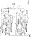
- the receiver apparatus configuration design illustrated in Figure 1 can be implemented for the case of known delay and phase values but unknown amplitude values for the data signal to be received.
- This design contains a block that theoretically includes the modulation schemes that can be possibly used. It also contains three different shaping pulses. Furthermore, non - coherent detection as well as uniform PDP are assumed.
- Example 3 Known data signal phase value, unknown data signal delay and amplitude values: non-coherent detection
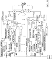
- the receiver design illustrated in Figure 2 can be implemented for the case of known phases but unknown delays and amplitudes. As in the above case, this design contains a block that theoretically includes the modulation schemes that can be possibly used together with the shaping pulses. Furthermore, non-coherent detection as well as uniform power decay profile (PDP) have been assumed.
- PDP uniform power decay profile
- conditional probability p r l t l 1 Lp
- JPDF joint probability density function
- Example 5 Known delay values, unknown phase and amplitude values for a received data signal: non-coherent detection
- Equation (33) cannot be solved in closed-form as currently expressed.
- the additional factor of complexity in this case is the modified Bessel function.
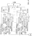
- the receiver design illustrated in Figure 3 can be implemented for the case of known delays but unknown phases and amplitudes.
- this design contains a block that theoretically includes the modulation schemes that can be possibly used together with shaping pulses.
- coherent detection as well as uniform PDP have been selected in this design.
- Example 6 Unknown phase, delay and amplitude values for a received data signal: non-coherent detection
- this design contains a block that theoretically includes the modulation schemes that can be possibly used together with the shaping pulses. Furthermore, coherent detection as well as uniform PDP have been selected in this design.
- the Power Decay Profile critically affects the performance of wireless communications systems and it is always considered as a factor of significant importance during the system design process.
- the PDP is considered to be of the same nature in all diversity paths between transmitter and receiver.
- Uniform PDP indicates the uniform rate of variation of the power of the signal while Exponential PDP indicates its exponential variation.
- the nature of the PDP determines the degree of optimisation of a receiver design. For uniform PDP, the receiver design is considered optimum, while, for non-uniform PDP (exponential in our case), the receiver design is considered suboptimum.
- the data signal which is transmitted can be shaped in a desired waveform which will make it relatively easier for the receiver to filter the received signals effectively and extract the information included in it.
- the typical shaping pulses that are used are the square, sinusoidal and cosine.
- Digital modulation techniques can be an important factor in the transmission of digital data in order to achieve the highest possible data transmission rates.
- the higher the order of the modulation the higher the spectral efficiency i.e. the higher the number of bits per transmitted symbol.
- the complexity, and hence, the cost increase dramatically.
- the information symbols are located very close to each other which results in inter symbol interference (ISI). This increases the error rate and raises the need for more sophisticated, complex and costly receiver designs. Therefore, the choice of the appropriate modulation scheme for each system is relative to the performance requirements of it.
- Six types of digital modulations namely, M-PSK, M-QAM, ASK/PAM, FSK, MSK and OFDM can be expressed mathematically as follows:
- g(t) stands for the shaping pulse
- f c the carrier frequency
- M the number of symbol states
- MSK A mc cos ⁇ 2 cos 2 t ⁇ f c t ⁇ A ms ⁇ sin t 2 sin 2 ⁇ f c t
- the configuration design of the receiving apparatus can be achieved by referring to the appropriate decision metric.
- four basic receiver designs are produced directly from the four different derived decision metrics in equations (20), (24), (37), (40).
- the PDP was considered uniform in the four initial designs.
- receiver designs with coherent and non-coherent detection under exponential PDP can be produced in a straightforward manner.
Landscapes
- Engineering & Computer Science (AREA)
- Power Engineering (AREA)
- Computer Networks & Wireless Communication (AREA)
- Signal Processing (AREA)
- Digital Transmission Methods That Use Modulated Carrier Waves (AREA)
- Radio Transmission System (AREA)
Description
- The invention to which this application relates is a broadcast data receiver apparatus which is provided in a form so as to have an improved response to long and short term fading of the data channels.
- The demand for increased capacity in data receiving apparatus, and/or reduced information errors continues to grow and there is also an increasing demand for generally efficient operation of wireless communication systems. However, a fundamental constraint to the capacity of the data transmission and receiving system is one or both of the digital receiver and the propagation medium (i.e the channel on which the data is transmitted).
- Broadcast signals which are transmitted are typically distorted by atmospheric and environmental impairments, thereby degrading the quality of the signal which is subsequently received. In general, one form of deterioration is fading which is typically caused by physical phenomena such as reflection, diffraction and scattering. According to the number of the scattering phenomena which may be present in a wireless channel, the effect of these phenomena is either rich or poor. This is the case in the occurrence of multipath and shadowing fading, respectively.
- It is known from the theory of telecommunications that multipath fading and shadowing of propagated signals, (also known as short-term fading and long-term fading respectively), can be effectively described and represented by statistical distributions.
- Conventionally used distributions such as those known as Rayleigh, Weibull and Nakagami -m, -n, -q distributions, are adequate when describing multipath fading. However, they are found not to be optimal and/or robust because they do not additionally consider the simultaneous occurrence of the shadowing effect.
- Another known distribution known as the Suzuki statistical distribution has the advantage that it is a composite Rayleigh/Lognormal distribution. As a consequence, it is capable of describing at once both the multipath and the shadowing of communication signals which occur simultaneously during wireless propagation. However, the probability density function (PDF) of the Suzuki distribution is described by the integral of the synthesis of Lognormal and Rayleigh, distribution. An explicit solution to this integral is not known in the prior art and thus it has not been possible to implement a receiver for a digital data system which is operable over such a fading channel. The document in the name of Coulson AJ et al entitled "Improving fading distribution for mobile radio" Proceedings of IEE, vol.145, no.3, 16 June 1998, pages 197-202 discloses the use of Suzuki distribution in data signal decoding.
- An existing method of compensating for shadowing is by providing the receiver with empirical data, i.e. actual data, relating to the geographical area in which the receiver is to be used. However, it is time-consuming to produce such data, the data is not always specific enough to the receiver location, and if the receiver is moved to a new location, new empirical data has to be obtained.
- An aim of the present invention is to provide a receiver which can characterise accurately the signal degradation caused by the presence of multipath fading and shadowing. Another aim is to provide a method whereby the characterisation of the signal degradation can be accurately determined.
- In one aspect of the invention, there is provided a broadcast receiver, said receiver including processing means used to receive the data signal, wherein the receiver is configured to receive the said data signal with respect to at least one decision metric derived upon utilising the probability density function of a Suzuki distribution of the said data signal_ in order to take into account potential impairment of the said data signal and the selection of the decision metric used is made with regard to whether any or any combination of values for the phase, delay and/or amplitude of the said data signal is known characterised in that when the phase and delay values are known the decision metric used is



when the delay, amplitude and phase values are unknown the decision metric used is


- Thus the receiver can be optimised in a number of conditions such that the requirement for empirically modelling the channel before deploying a new network is removed. As such the receiver has improved performance over fading channels and is adaptive to the location of the receiver.
- In one embodiment the design or configuration of the receiving apparatus include details of coherent detection as well as non-coherent detection.
- In one embodiment the designs include details of the possible modulation schemes, typically M-PSK, M-QAM, ASK/PAM, FSK, MSK and OFDM.
- In one embodiment the designs include a plurality of shaping pulses, typically square, sinusoidal and cosine.
- In one embodiment the broadcast receiver characterises signal impairment optimally by utilising any, or any combination of, the decision metrics described herein.
- Typically, according to the level of channel knowledge, the decision metric allows optimisation of the signal reception parameters or design.
- In a further aspect of the invention there is provided a method of configuring receiving and/or processing apparatus for at least one data signal received from a remote transmitting location said method including the steps of:
- identifying the data signal which is to be received and wherein the said apparatus is further configured with reference to a decision metric derived upon utilising the probability density function of a Suzuki distribution in order to take into account potential impairment of the said data signal and the selection of the decision metric used is made with regard to whether any or any combination of values for the phase, delay and/or amplitude of the said data signal is known characterised in that when the phase and delay values are known the decision metric used is

- when only the phase value is known the decision metrics used are


- when the delay and amplitude values are known the decision metric used is

- when only the delay value is known the decision metric used is .

- when the delay, amplitude and phase values are unknown the decision metric used is


- where S̃k(t) is the corresponding kth complex baseband signal chosen from the set of M equi-probable message waveforms which represents the transmitted data signal, Lp are the independent diversity paths, and


- Further details of specific embodiments are now described wherein:-
-
Figure 1 illustrates a receiver apparatus configuration design for the case of known delay and phase values but unknown amplitude values for a data signal to be received. -
Figure 2 illustrates a receiver apparatus configuration design for the case of known phase value but unknown delay and amplitude values for a received data signal. -
Figure 3 illustrates a receiver apparatus configuration design for the case of a known delay value but unknown phase and amplitude values of a received data signal. -
Figure 4 illustrates a receiver apparatus configuration design for receipt of a data signal for which the delay, phase and amplitude values are unknown. - In the transmission of a data signal to one or more receiver apparatus then during a symbol period of 'Ts' seconds of the data signal the transmitter transmits a real bandpass signal which can be represented as :

- The above signal (1) is transmitted over the fading channel which is characterized by Lp independent diversity paths. Each of these paths is a time varying channel that attenuates, delays, phase-shifts the signal while it also adds an AWGN source. Thus, the received data signal at the receiving apparatus is in fact a set of "noisy" replicas of the transmitted signal.
- It should be noted here that a so-called "one-shot" approach for the transmission of the data signal is assumed to be used herein i.e. a single transmission wherein ISI that would be produced by the presence of the path delays on continuous transmission is ignored. Hence, the received signal will be expressed as follows:
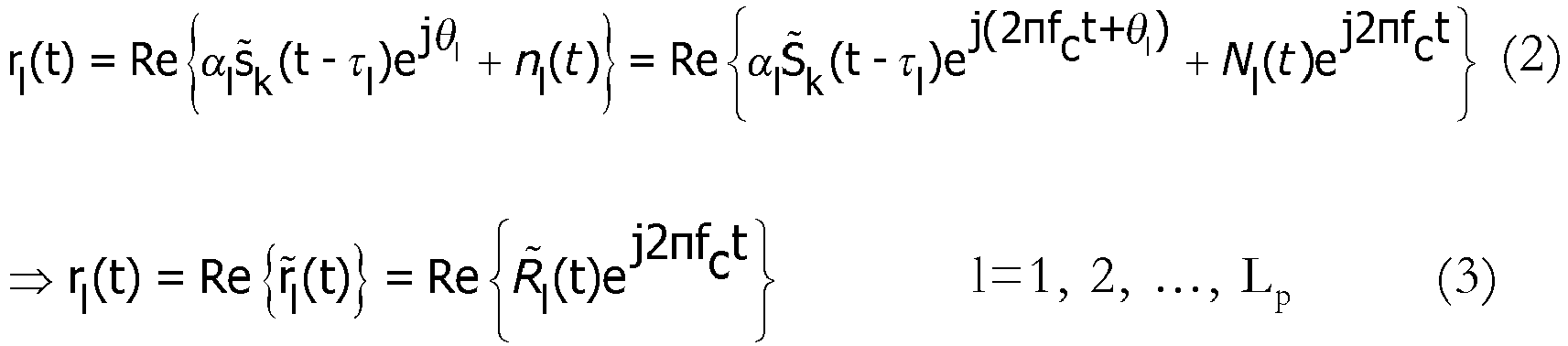

- The sets


- Another important assumption is that τ1 < τ2 < ... < τLp. The optimum receiver computes the set of a posteriori probabilities

- Since the messages (signals) are assumed to be equi-probable, then, by Bayes' rule, the equivalent decision rule is to choose s k(t) corresponding to the largest of the conditional probabilities (likelihoods)


- In case that any of the three parameter sets are assumed to be known, then the statistical averages on that set of parameters need not be performed. Of course, in the case where all parameters are assumed to be known to the receiver, none of the statistical averages in (4) need be performed and as a consequence the ML decision rule simplifies to choosing the largest of:

- Receivers that make use of CSI have been termed self-adaptive in that the estimates of the system parameters are utilized to adjust the decision structure, thereby, improving the system performance by adaptation to variation of the channel changes.
- Conditioned on perfect knowledge of the amplitudes, phases and delays, the conditional probability


- When the amplitudes of the received data signal are unknown, then the conditional probability of equation (6), must be averaged over their Joint Probability Density Function (JPDF) to arrive at the decision metric. Assuming independent amplitudes with first-order PDFs


- According to the invention, the PDF of Suzuki distribution is expressed mathematically as:

- σ = the variance of Lognormal distribution
- µ = mean value of lognormal distribution
- Therefore, by inserting equation (12) into equation (11) we obtain analytically:

- The integral in (13) can not be solved in closed-form as currently expressed, mainly due to the summation term under the power term. By assuming that


- Equation (13) can become respectively,


- The closed-form solution of each of the above two equations are given below as follows


- Having managed to obtain (13) in a closed-form, the natural logarithm of it is taken in order to derive the decision metric of a receiver that has knowledge of the delays and phases of a Suzuki fading channel but not amplitudes. Therefore, one obtains:

- Based on that decision metric the receiver apparatus configuration design illustrated in
Figure 1 can be implemented for the case of known delay and phase values but unknown amplitude values for the data signal to be received. This design contains a block that theoretically includes the modulation schemes that can be possibly used. It also contains three different shaping pulses. Furthermore, non - coherent detection as well as uniform PDP are assumed. - After deriving successfully the decision metric for the case of known phases and delays but unknown amplitudes, we can derive next the decision metric for the case of known phases but unknown delays and amplitudes. However, it should be mentioned here that in typical practical applications, the fact that the phases are known while the delays are unknown is considered unorthodox. However, in quite narrowband systems (like OFDM) recent developments can make the realisation of such schemes possible. This can actually happen by determining the delays by the phase difference. Therefore, this design will be implemented since such case may attract more attention in future applications.
- It is obvious that the difference between the current and the previous scheme is the lack of knowledge of the path delays. Hence, one has to average over the statistics of both amplitude and time, i.e, pα
l (αl ) and pτl (τl ). - The former is expressed by equation (12) while the latter is expressed by Alouini - initially Charash- as:

- Thus, the decision metric is expressed mathematically as follows:


l (τ l) is absorbed within the constant 'K'. - Therefore, it is straightforward to obtain the closed form expression for the decision metric:


- Based on the decision metric expressed by equations (23) and (24), the receiver design illustrated in
Figure 2 can be implemented for the case of known phases but unknown delays and amplitudes. As in the above case, this design contains a block that theoretically includes the modulation schemes that can be possibly used together with the shaping pulses. Furthermore, non-coherent detection as well as uniform power decay profile (PDP) have been assumed. - In the case of known delay and amplitude values but unknown phase value the scheme is independent of the novel expression for the PDF of Suzuki distribution. However, the analysis of this scheme is vital since the derived results are used in the derivation process of any scheme that the phases are considered unknown.
- When the phases are unknown, then the conditional probability
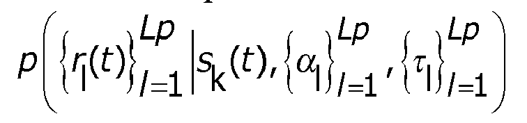

- The case of known delay values but unknown phase and amplitude values is perhaps the most critical design to be considered for wireless communication engineering applications and the appropriate configuration of the receiving apparatus for the data signals, and can be derived from the closed form solution for the decision metric of the case of known delays and amplitude values but unknown phase values.
- The equation (28) is averaged over the PDF of Suzuki distribution pα
l (αl ). In other words, the mathematical expression of the decision metric of this scheme is the following:

- Equation (33) cannot be solved in closed-form as currently expressed. The additional factor of complexity in this case is the modified Bessel function.
- In order to simplify the summation term under the power term of Suzuki PDF, two assumptions were made based on the value of αl. The range of values of each of these two assumptions quite coincide with the range of values of the asymptotes of the modified Bessel function. In more detail, the modified Bessel function can be also expressed as:

- Therefore, by taking into consideration equation (34) as well as the assumptions in (14) and (15), we obtain respectively,


- Based on that decision metric the receiver design illustrated in
Figure 3 can be implemented for the case of known delays but unknown phases and amplitudes. As in the above case, this design contains a block that theoretically includes the modulation schemes that can be possibly used together with shaping pulses. Furthermore, coherent detection as well as uniform PDP have been selected in this design. - When all channel parameters are unknown, the conditional probability has to be averaged over the statistics of the amplitudes, phases and delays which all are assumed statistically independent. However, since the decision metric has been derived for the case of known delays but unknown amplitudes and phases, we only need to average this metric over the PDF of time. The same methodology was followed above in the case of known phases but unknown amplitudes and delays. Therefore, the following expression must be solved in closed-form:


- Based on this decision metric we can implement the receiver design as illustrated in
Figure 4 for the case of unknown delays, phases and amplitudes. As in the above case, this design contains a block that theoretically includes the modulation schemes that can be possibly used together with the shaping pulses. Furthermore, coherent detection as well as uniform PDP have been selected in this design. - The Power Decay Profile (PDP) critically affects the performance of wireless communications systems and it is always considered as a factor of significant importance during the system design process. In the majority of systems, the PDP is typically considered to be flat i.e. Ω1 = Ω; l = 1, 2, ..., Lp. The PDP is considered to be of the same nature in all diversity paths between transmitter and receiver.
- Uniform PDP indicates the uniform rate of variation of the power of the signal while Exponential PDP indicates its exponential variation. The PDP is described mathematically as follows:


- In the present case we will consider the values δ = 0, 0.1, 0.5, 1.0, 2.0, while it is obvious that for δ = 0, the exponential PDP becomes uniform PDP.
- In addition, the nature of the PDP determines the degree of optimisation of a receiver design. For uniform PDP, the receiver design is considered optimum, while, for non-uniform PDP (exponential in our case), the receiver design is considered suboptimum.
- Hereinabove it is assumed that the channel is constant for one symbol period i.e. the detection is considered non-coherent. However, it is well known that coherent detection is always desired ideally. Coherent detection assumes that the channel remains constant for at least two symbol periods. This can be realised mathematically by changing the upper limit of the integral in equation (7) from 'Ts +τ1' to '2Ts +τ1'. Therefore, only the term 'ykl' changes and varies proportionally the value decision metric. Hence, this small change of 'Ts' to '2Ts' is the difference between the optimum/suboptimum receiver designs with non-coherent and coherent detection respectively.
- Using shaping pulses in the transmitter, the data signal which is transmitted can be shaped in a desired waveform which will make it relatively easier for the receiver to filter the received signals effectively and extract the information included in it. The typical shaping pulses that are used are the square, sinusoidal and cosine. These three pulses are expressed mathematically, respectively, as follows:



- Digital modulation techniques can be an important factor in the transmission of digital data in order to achieve the highest possible data transmission rates. The higher the order of the modulation, the higher the spectral efficiency i.e. the higher the number of bits per transmitted symbol. However, in high order modulation schemes the complexity, and hence, the cost increase dramatically. In addition, the information symbols are located very close to each other which results in inter symbol interference (ISI). This increases the error rate and raises the need for more sophisticated, complex and costly receiver designs. Therefore, the choice of the appropriate modulation scheme for each system is relative to the performance requirements of it. Six types of digital modulations, namely, M-PSK, M-QAM, ASK/PAM, FSK, MSK and OFDM can be expressed mathematically as follows:
-

-

-

-

-

-


- Thus in accordance with the invention the configuration design of the receiving apparatus can be achieved by referring to the appropriate decision metric. As indicated above and in
Figures 1-4 , four basic receiver designs are produced directly from the four different derived decision metrics in equations (20), (24), (37), (40). - However, where non-coherent detection is provided in these designs, four modified designs can be produced for the cases of coherent detection.
- In addition, the PDP was considered uniform in the four initial designs. Hence receiver designs with coherent and non-coherent detection under exponential PDP can be produced in a straightforward manner. In addition, each of the designs can be changed to take into account the six modulation schemes, and different shaping pulses can be used in all schemes except MSK and OFDM. Therefore, the number of receiver configuration designs which can be achieved are :

Claims (9)
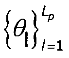
- A broadcast receiver, said receiver including processing means used to receive the data signal, r1 (t) wherein the receiver is configured to receive the said data signal with respect to at least one decision metric derived upon utilising the probability density function of a Suzuki distribution of the said data signal in order to take into account potential impairment of the said data signal and the selection of the decision metric used is made with regard to whether any or any combination of values for the phase, delay and/or amplitude of the said data signal is known characterised in that when the phase and delay values are known the decision metric used is


when the delay, amplitude and phase values are unknown the decision metric used is



- A broadcast receiver according to claim 1 wherein the receiver is optimised in a plurality of conditions with respect to the geographical location in which the receiver is to be used.
- A broadcast receiver according to claim 1 wherein the data signal impairment is with respect to the fading of the data signal channel.
- A broadcast data receiver according to claim 1 wherein the configuration of the receiver includes details relating to coherent detection as well as non-coherent detection.
- A broadcast receiver according to claim 1 wherein the configuration of the receiver includes details of possible modulation schemes to be used.
- A broadcast receiver according to claim 1 wherein the receiver is configured to receive data signals which are provided using shaping pulses.
- A broadcast data receiver including receiving apparatus which has been configured with reference to a decision metric as set out in claim 1.
- A method of configuring receiving and/or processing apparatus for at least one data signal received from a remote transmitting location, rl(t), said method including the steps of:identifying the data signal which is to be received and wherein the said apparatus is further configured with reference to a decision metric derived upon utilising the probability density function of a Suzuki distribution in order to take into account potential impairment of the said data signal and the selection of the decision metric used is made with regard to whether any or any combination of values for the phase, delay and/or amplitude of the said data signal is known characterised in that when the phase and delay values are known the decision metric used is
 when only the phase value is known the decision metrics used are
 when the delay and amplitude values are known the decision metric used is
 when only the delay value is known the decision metric used is .
 when the delay, amplitude and phase values are unknown the decision metric used is
 where sk(t) is the corresponding kth complex baseband signal chosen from the set of M equi-probable message waveforms which represents the transmitted data signal, Lp are the independent diversity paths, and

- A method according to claim 8 wherein the method includes the step of identifying the geographical location at which the said apparatus is to be used.
Applications Claiming Priority (1)
| Application Number | Priority Date | Filing Date | Title |
|---|---|---|---|
| GBGB1004946.8A GB201004946D0 (en) | 2010-03-24 | 2010-03-24 | Receiver with improved response to long and short term fading |
Publications (3)
| Publication Number | Publication Date |
|---|---|
| EP2369801A2 EP2369801A2 (en) | 2011-09-28 |
| EP2369801A3 EP2369801A3 (en) | 2012-10-24 |
| EP2369801B1 true EP2369801B1 (en) | 2017-11-22 |
Family
ID=42228269
Family Applications (1)
| Application Number | Title | Priority Date | Filing Date |
|---|---|---|---|
| EP11159476.8A Active EP2369801B1 (en) | 2010-03-24 | 2011-03-23 | Data receiver with improved response to long and short term data signal fading |
Country Status (3)
| Country | Link |
|---|---|
| US (1) | US8654907B2 (en) |
| EP (1) | EP2369801B1 (en) |
| GB (1) | GB201004946D0 (en) |
Family Cites Families (1)
| Publication number | Priority date | Publication date | Assignee | Title |
|---|---|---|---|---|
| US7280942B2 (en) * | 2005-08-15 | 2007-10-09 | Mitsubishi Electric Research Laboratories, Inc. | Method for representing a combination of signals with a distribution of a single lognormal random variable |
-
2010
- 2010-03-24 GB GBGB1004946.8A patent/GB201004946D0/en not_active Ceased
-
2011
- 2011-03-23 EP EP11159476.8A patent/EP2369801B1/en active Active
- 2011-03-24 US US13/070,587 patent/US8654907B2/en active Active
Non-Patent Citations (1)
| Title |
|---|
| None * |
Also Published As
| Publication number | Publication date |
|---|---|
| GB201004946D0 (en) | 2010-05-12 |
| EP2369801A2 (en) | 2011-09-28 |
| US8654907B2 (en) | 2014-02-18 |
| US20120014481A1 (en) | 2012-01-19 |
| EP2369801A3 (en) | 2012-10-24 |
Similar Documents
| Publication | Publication Date | Title |
|---|---|---|
| Li et al. | Transmitter diversity for OFDM systems and its impact on high-rate data wireless networks | |
| Yan et al. | Receiver design for downlink non-orthogonal multiple access (NOMA) | |
| EP1611723B1 (en) | Position adjusted guard time interval for ofdm-communications system | |
| EP1821444B1 (en) | Apparatus and method for transmission and reception in a multi-user MIMO communication system | |
| US8462613B2 (en) | Channel estimation for long term evolution (LTE) terminals | |
| US8665832B2 (en) | Device, channel quality estimation method, and transmission method | |
| US10644904B2 (en) | System and method for channel estimation | |
| US20120219093A1 (en) | Method and apparatus for channel quality measurements | |
| US20070104280A1 (en) | Wireless data transmission method, and corresponding signal, system, transmitter and receiver | |
| JP4470377B2 (en) | Propagation path estimation method in mobile communication system | |
| Ekpenyong et al. | Feedback constraints for adaptive transmission | |
| Samara et al. | Adapt and aggregate: Adaptive OFDM numerology and carrier aggregation for high data rate terahertz communications | |
| CN103532881B (en) | A kind of method of self-adaptative adjustment single carrier underwater acoustic coherent communication standard | |
| Nissel et al. | Closed-form capacity expression for low complexity BICM with uniform inputs | |
| US20030128749A1 (en) | Method and device for the automatic selection of the bit rate in high frequency transmissions | |
| EP2369801A2 (en) | Data receiver with improved response to long and short term data signal fading | |
| Uryvsky et al. | Applied research of modulation-coding schemes selection algorithms effectiveness in 802.11 equipment | |
| EP1983708B1 (en) | Method and apparatus for generating training sequence codes in a communication system | |
| Wan et al. | Time synchronization for cooperative communication in wireless sensor networks | |
| Liu et al. | OTFS-Based Spatial Modulation for Multi-Satellite Cooperative Communication Systems | |
| Barbieri et al. | Improving the spectral efficiency of linear modulations through time-frequency packing | |
| Poikonen | Efficient channel modeling methods for mobile communication systems | |
| Zhang et al. | Flexible FTN-OTFS for High-Mobility LEO Satellite-to-Ground Communication | |
| Upadhyay et al. | A Comparative Study on Spatial Diversity Techniques in Multiantenna Systems over Various Fading Channels | |
| Matthew | NGINEE, RING llflRAR' |
Legal Events
| Date | Code | Title | Description |
|---|---|---|---|
| PUAI | Public reference made under article 153(3) epc to a published international application that has entered the european phase |
Free format text: ORIGINAL CODE: 0009012 |
|
| AK | Designated contracting states |
Kind code of ref document: A2 Designated state(s): AL AT BE BG CH CY CZ DE DK EE ES FI FR GB GR HR HU IE IS IT LI LT LU LV MC MK MT NL NO PL PT RO RS SE SI SK SM TR |
|
| AX | Request for extension of the european patent |
Extension state: BA ME |
|
| PUAL | Search report despatched |
Free format text: ORIGINAL CODE: 0009013 |
|
| AK | Designated contracting states |
Kind code of ref document: A3 Designated state(s): AL AT BE BG CH CY CZ DE DK EE ES FI FR GB GR HR HU IE IS IT LI LT LU LV MC MK MT NL NO PL PT RO RS SE SI SK SM TR |
|
| AX | Request for extension of the european patent |
Extension state: BA ME |
|
| RIC1 | Information provided on ipc code assigned before grant |
Ipc: H04L 25/06 20060101ALI20120920BHEP Ipc: H04L 25/03 20060101AFI20120920BHEP |
|
| 17P | Request for examination filed |
Effective date: 20130326 |
|
| GRAP | Despatch of communication of intention to grant a patent |
Free format text: ORIGINAL CODE: EPIDOSNIGR1 |
|
| INTG | Intention to grant announced |
Effective date: 20170620 |
|
| GRAS | Grant fee paid |
Free format text: ORIGINAL CODE: EPIDOSNIGR3 |
|
| GRAA | (expected) grant |
Free format text: ORIGINAL CODE: 0009210 |
|
| AK | Designated contracting states |
Kind code of ref document: B1 Designated state(s): AL AT BE BG CH CY CZ DE DK EE ES FI FR GB GR HR HU IE IS IT LI LT LU LV MC MK MT NL NO PL PT RO RS SE SI SK SM TR |
|
| REG | Reference to a national code |
Ref country code: GB Ref legal event code: FG4D |
|
| REG | Reference to a national code |
Ref country code: CH Ref legal event code: EP |
|
| REG | Reference to a national code |
Ref country code: IE Ref legal event code: FG4D |
|
| REG | Reference to a national code |
Ref country code: AT Ref legal event code: REF Ref document number: 949361 Country of ref document: AT Kind code of ref document: T Effective date: 20171215 |
|
| RAP2 | Party data changed (patent owner data changed or rights of a patent transferred) |
Owner name: ARRIS GLOBAL LTD. |
|
| REG | Reference to a national code |
Ref country code: DE Ref legal event code: R096 Ref document number: 602011043512 Country of ref document: DE |
|
| REG | Reference to a national code |
Ref country code: DE Ref legal event code: R082 Ref document number: 602011043512 Country of ref document: DE Representative=s name: KASTEL PATENTANWAELTE, DE Ref country code: DE Ref legal event code: R081 Ref document number: 602011043512 Country of ref document: DE Owner name: ARRIS GLOBAL LTD, GB Free format text: FORMER OWNER: PACE PLC, SHIPLEY, WEST YORKSHIRE, GB Ref country code: DE Ref legal event code: R082 Ref document number: 602011043512 Country of ref document: DE Representative=s name: KASTEL PATENTANWAELTE PARTG MBB, DE |
|
| REG | Reference to a national code |
Ref country code: NL Ref legal event code: MP Effective date: 20171122 |
|
| REG | Reference to a national code |
Ref country code: LT Ref legal event code: MG4D |
|
| REG | Reference to a national code |
Ref country code: AT Ref legal event code: MK05 Ref document number: 949361 Country of ref document: AT Kind code of ref document: T Effective date: 20171122 |
|
| PG25 | Lapsed in a contracting state [announced via postgrant information from national office to epo] |
Ref country code: SE Free format text: LAPSE BECAUSE OF FAILURE TO SUBMIT A TRANSLATION OF THE DESCRIPTION OR TO PAY THE FEE WITHIN THE PRESCRIBED TIME-LIMIT Effective date: 20171122 Ref country code: ES Free format text: LAPSE BECAUSE OF FAILURE TO SUBMIT A TRANSLATION OF THE DESCRIPTION OR TO PAY THE FEE WITHIN THE PRESCRIBED TIME-LIMIT Effective date: 20171122 Ref country code: NO Free format text: LAPSE BECAUSE OF FAILURE TO SUBMIT A TRANSLATION OF THE DESCRIPTION OR TO PAY THE FEE WITHIN THE PRESCRIBED TIME-LIMIT Effective date: 20180222 Ref country code: FI Free format text: LAPSE BECAUSE OF FAILURE TO SUBMIT A TRANSLATION OF THE DESCRIPTION OR TO PAY THE FEE WITHIN THE PRESCRIBED TIME-LIMIT Effective date: 20171122 Ref country code: LT Free format text: LAPSE BECAUSE OF FAILURE TO SUBMIT A TRANSLATION OF THE DESCRIPTION OR TO PAY THE FEE WITHIN THE PRESCRIBED TIME-LIMIT Effective date: 20171122 Ref country code: NL Free format text: LAPSE BECAUSE OF FAILURE TO SUBMIT A TRANSLATION OF THE DESCRIPTION OR TO PAY THE FEE WITHIN THE PRESCRIBED TIME-LIMIT Effective date: 20171122 |
|
| PG25 | Lapsed in a contracting state [announced via postgrant information from national office to epo] |
Ref country code: GR Free format text: LAPSE BECAUSE OF FAILURE TO SUBMIT A TRANSLATION OF THE DESCRIPTION OR TO PAY THE FEE WITHIN THE PRESCRIBED TIME-LIMIT Effective date: 20180223 Ref country code: LV Free format text: LAPSE BECAUSE OF FAILURE TO SUBMIT A TRANSLATION OF THE DESCRIPTION OR TO PAY THE FEE WITHIN THE PRESCRIBED TIME-LIMIT Effective date: 20171122 Ref country code: BG Free format text: LAPSE BECAUSE OF FAILURE TO SUBMIT A TRANSLATION OF THE DESCRIPTION OR TO PAY THE FEE WITHIN THE PRESCRIBED TIME-LIMIT Effective date: 20180222 Ref country code: RS Free format text: LAPSE BECAUSE OF FAILURE TO SUBMIT A TRANSLATION OF THE DESCRIPTION OR TO PAY THE FEE WITHIN THE PRESCRIBED TIME-LIMIT Effective date: 20171122 Ref country code: AT Free format text: LAPSE BECAUSE OF FAILURE TO SUBMIT A TRANSLATION OF THE DESCRIPTION OR TO PAY THE FEE WITHIN THE PRESCRIBED TIME-LIMIT Effective date: 20171122 Ref country code: HR Free format text: LAPSE BECAUSE OF FAILURE TO SUBMIT A TRANSLATION OF THE DESCRIPTION OR TO PAY THE FEE WITHIN THE PRESCRIBED TIME-LIMIT Effective date: 20171122 |
|
| PG25 | Lapsed in a contracting state [announced via postgrant information from national office to epo] |
Ref country code: CY Free format text: LAPSE BECAUSE OF FAILURE TO SUBMIT A TRANSLATION OF THE DESCRIPTION OR TO PAY THE FEE WITHIN THE PRESCRIBED TIME-LIMIT Effective date: 20171122 Ref country code: EE Free format text: LAPSE BECAUSE OF FAILURE TO SUBMIT A TRANSLATION OF THE DESCRIPTION OR TO PAY THE FEE WITHIN THE PRESCRIBED TIME-LIMIT Effective date: 20171122 Ref country code: DK Free format text: LAPSE BECAUSE OF FAILURE TO SUBMIT A TRANSLATION OF THE DESCRIPTION OR TO PAY THE FEE WITHIN THE PRESCRIBED TIME-LIMIT Effective date: 20171122 Ref country code: CZ Free format text: LAPSE BECAUSE OF FAILURE TO SUBMIT A TRANSLATION OF THE DESCRIPTION OR TO PAY THE FEE WITHIN THE PRESCRIBED TIME-LIMIT Effective date: 20171122 Ref country code: SK Free format text: LAPSE BECAUSE OF FAILURE TO SUBMIT A TRANSLATION OF THE DESCRIPTION OR TO PAY THE FEE WITHIN THE PRESCRIBED TIME-LIMIT Effective date: 20171122 |
|
| REG | Reference to a national code |
Ref country code: DE Ref legal event code: R097 Ref document number: 602011043512 Country of ref document: DE |
|
| PG25 | Lapsed in a contracting state [announced via postgrant information from national office to epo] |
Ref country code: PL Free format text: LAPSE BECAUSE OF FAILURE TO SUBMIT A TRANSLATION OF THE DESCRIPTION OR TO PAY THE FEE WITHIN THE PRESCRIBED TIME-LIMIT Effective date: 20171122 Ref country code: SM Free format text: LAPSE BECAUSE OF FAILURE TO SUBMIT A TRANSLATION OF THE DESCRIPTION OR TO PAY THE FEE WITHIN THE PRESCRIBED TIME-LIMIT Effective date: 20171122 Ref country code: RO Free format text: LAPSE BECAUSE OF FAILURE TO SUBMIT A TRANSLATION OF THE DESCRIPTION OR TO PAY THE FEE WITHIN THE PRESCRIBED TIME-LIMIT Effective date: 20171122 Ref country code: IT Free format text: LAPSE BECAUSE OF FAILURE TO SUBMIT A TRANSLATION OF THE DESCRIPTION OR TO PAY THE FEE WITHIN THE PRESCRIBED TIME-LIMIT Effective date: 20171122 |
|
| PLBE | No opposition filed within time limit |
Free format text: ORIGINAL CODE: 0009261 |
|
| STAA | Information on the status of an ep patent application or granted ep patent |
Free format text: STATUS: NO OPPOSITION FILED WITHIN TIME LIMIT |
|
| 26N | No opposition filed |
Effective date: 20180823 |
|
| REG | Reference to a national code |
Ref country code: CH Ref legal event code: PL |
|
| PG25 | Lapsed in a contracting state [announced via postgrant information from national office to epo] |
Ref country code: MC Free format text: LAPSE BECAUSE OF FAILURE TO SUBMIT A TRANSLATION OF THE DESCRIPTION OR TO PAY THE FEE WITHIN THE PRESCRIBED TIME-LIMIT Effective date: 20171122 Ref country code: SI Free format text: LAPSE BECAUSE OF FAILURE TO SUBMIT A TRANSLATION OF THE DESCRIPTION OR TO PAY THE FEE WITHIN THE PRESCRIBED TIME-LIMIT Effective date: 20171122 |
|
| REG | Reference to a national code |
Ref country code: BE Ref legal event code: MM Effective date: 20180331 |
|
| REG | Reference to a national code |
Ref country code: IE Ref legal event code: MM4A |
|
| PG25 | Lapsed in a contracting state [announced via postgrant information from national office to epo] |
Ref country code: LU Free format text: LAPSE BECAUSE OF NON-PAYMENT OF DUE FEES Effective date: 20180323 |
|
| PG25 | Lapsed in a contracting state [announced via postgrant information from national office to epo] |
Ref country code: IE Free format text: LAPSE BECAUSE OF NON-PAYMENT OF DUE FEES Effective date: 20180323 |
|
| PG25 | Lapsed in a contracting state [announced via postgrant information from national office to epo] |
Ref country code: CH Free format text: LAPSE BECAUSE OF NON-PAYMENT OF DUE FEES Effective date: 20180331 Ref country code: LI Free format text: LAPSE BECAUSE OF NON-PAYMENT OF DUE FEES Effective date: 20180331 Ref country code: BE Free format text: LAPSE BECAUSE OF NON-PAYMENT OF DUE FEES Effective date: 20180331 |
|
| PG25 | Lapsed in a contracting state [announced via postgrant information from national office to epo] |
Ref country code: FR Free format text: LAPSE BECAUSE OF NON-PAYMENT OF DUE FEES Effective date: 20180331 |
|
| PG25 | Lapsed in a contracting state [announced via postgrant information from national office to epo] |
Ref country code: MT Free format text: LAPSE BECAUSE OF NON-PAYMENT OF DUE FEES Effective date: 20180323 |
|
| PG25 | Lapsed in a contracting state [announced via postgrant information from national office to epo] |
Ref country code: TR Free format text: LAPSE BECAUSE OF FAILURE TO SUBMIT A TRANSLATION OF THE DESCRIPTION OR TO PAY THE FEE WITHIN THE PRESCRIBED TIME-LIMIT Effective date: 20171122 |
|
| PG25 | Lapsed in a contracting state [announced via postgrant information from national office to epo] |
Ref country code: HU Free format text: LAPSE BECAUSE OF FAILURE TO SUBMIT A TRANSLATION OF THE DESCRIPTION OR TO PAY THE FEE WITHIN THE PRESCRIBED TIME-LIMIT; INVALID AB INITIO Effective date: 20110323 Ref country code: PT Free format text: LAPSE BECAUSE OF FAILURE TO SUBMIT A TRANSLATION OF THE DESCRIPTION OR TO PAY THE FEE WITHIN THE PRESCRIBED TIME-LIMIT Effective date: 20171122 |
|
| PG25 | Lapsed in a contracting state [announced via postgrant information from national office to epo] |
Ref country code: MK Free format text: LAPSE BECAUSE OF NON-PAYMENT OF DUE FEES Effective date: 20171122 |
|
| PG25 | Lapsed in a contracting state [announced via postgrant information from national office to epo] |
Ref country code: AL Free format text: LAPSE BECAUSE OF FAILURE TO SUBMIT A TRANSLATION OF THE DESCRIPTION OR TO PAY THE FEE WITHIN THE PRESCRIBED TIME-LIMIT Effective date: 20171122 Ref country code: IS Free format text: LAPSE BECAUSE OF FAILURE TO SUBMIT A TRANSLATION OF THE DESCRIPTION OR TO PAY THE FEE WITHIN THE PRESCRIBED TIME-LIMIT Effective date: 20180322 |
|
| P01 | Opt-out of the competence of the unified patent court (upc) registered |
Effective date: 20230530 |
|
| REG | Reference to a national code |
Ref country code: DE Ref legal event code: R081 Ref document number: 602011043512 Country of ref document: DE Owner name: ARRIS ENTERPRISES LLC (N. D. GES. D. STAATES D, US Free format text: FORMER OWNER: ARRIS GLOBAL LTD, SHIPLEY, GB Ref country code: DE Ref legal event code: R081 Ref document number: 602011043512 Country of ref document: DE Owner name: ANDREW WIRELESS SYSTEMS UK LTD., GB Free format text: FORMER OWNER: ARRIS GLOBAL LTD, SHIPLEY, GB |
|
| REG | Reference to a national code |
Ref country code: DE Ref legal event code: R081 Ref document number: 602011043512 Country of ref document: DE Owner name: ARRIS ENTERPRISES LLC (N. D. GES. D. STAATES D, US Free format text: FORMER OWNER: ANDREW WIRELESS SYSTEMS UK LTD., LONDON, GB |
|
| REG | Reference to a national code |
Ref country code: GB Ref legal event code: 732E Free format text: REGISTERED BETWEEN 20250213 AND 20250219 |
|
| PGFP | Annual fee paid to national office [announced via postgrant information from national office to epo] |
Ref country code: DE Payment date: 20250327 Year of fee payment: 15 |
|
| PGFP | Annual fee paid to national office [announced via postgrant information from national office to epo] |
Ref country code: GB Payment date: 20250327 Year of fee payment: 15 |