EP2369787A1 - Wireless communication device - Google Patents
Wireless communication device Download PDFInfo
- Publication number
- EP2369787A1 EP2369787A1 EP11158704A EP11158704A EP2369787A1 EP 2369787 A1 EP2369787 A1 EP 2369787A1 EP 11158704 A EP11158704 A EP 11158704A EP 11158704 A EP11158704 A EP 11158704A EP 2369787 A1 EP2369787 A1 EP 2369787A1
- Authority
- EP
- European Patent Office
- Prior art keywords
- wireless
- wireless communication
- communication device
- setting information
- case
- Prior art date
- Legal status (The legal status is an assumption and is not a legal conclusion. Google has not performed a legal analysis and makes no representation as to the accuracy of the status listed.)
- Granted
Links
Images



Classifications
-
- H—ELECTRICITY
- H04—ELECTRIC COMMUNICATION TECHNIQUE
- H04L—TRANSMISSION OF DIGITAL INFORMATION, e.g. TELEGRAPHIC COMMUNICATION
- H04L41/00—Arrangements for maintenance, administration or management of data switching networks, e.g. of packet switching networks
- H04L41/08—Configuration management of networks or network elements
- H04L41/0803—Configuration setting
-
- H—ELECTRICITY
- H04—ELECTRIC COMMUNICATION TECHNIQUE
- H04W—WIRELESS COMMUNICATION NETWORKS
- H04W76/00—Connection management
- H04W76/20—Manipulation of established connections
- H04W76/23—Manipulation of direct-mode connections
Definitions
- the present specification teaches a wireless communication device that communicates wirelessly with another wireless communication device.
- a wireless telephone that communicates wirelessly between a base unit and a handset is known (e.g., Japanese patent application publication No. H6-69870 ).
- the base unit and the handset communicate wirelessly directly and not via an access point. That is, an ad-hoc wireless communication technique is known.
- a technique where a pair of wireless communication devices wirelessly communicates indirectly via an access point i.e., an infrastructure wireless communication technique, is also known.
- the same wireless setting information e.g., authentication method, encryption method, etc.
- the pair of wireless communication devices cannot properly communicate wirelessly.
- a technique for inhibiting an occurrence of a phenomenon where a pair of wireless communication devices cannot properly communicate wirelessly.
- the first wireless communication device configured to be wirelessly connected with a second wireless communication device.
- the first wireless communication device may comprise a communication unit, a first sending unit, and a setting unit.
- the communication unit may be configured to communicate specific data with the second wireless communication device by utilizing a wireless connection according to wireless communication setting information for communicating the specific data.
- the first sending unit may be configured to send second wireless setting information to the second wireless communication device by utilizing a first wireless connection according to first wireless setting information in a case where an instruction is input, the instruction being for changing the first wireless setting information currently being set in the first wireless communication device as the wireless setting information for communicating the specific data to the second wireless setting information.
- the setting unit may be configured to newly set the second wireless setting information as the wireless setting information for communicating the specific data in a case where a predetermined signal is received, the predetermined signal sent from the second wireless communication device to the first wireless communication device when the second wireless communication device changes the first wireless setting information currently being set in the second wireless communication device to the second wireless setting information.
- the setting unit may be configured to maintain the first wireless setting information as the wireless setting information for communicating the specific data in a case where the predetermined signal is not received.
- the following problem could occur if a configuration (termed “specific configuration” below) is adopted, regardless of whether the predetermined signal is received, the setting is changed from the first wireless setting information to the second wireless setting information after the first wireless communication device has sent the second wireless setting information to the second wireless communication device.
- a configuration termed “specific configuration” below
- the second wireless communication device will properly change the setting from the first wireless setting information to the second wireless setting information. Consequently, in the aforementioned specific configuration, the phenomenon where the first wireless communication device may change the setting to the second wireless setting information, but the second wireless communication device may not change the setting, and may maintain the first wireless setting information can occur.
- the first wireless communication device disclosed in the present specification changes the setting to the second wireless setting information in the case where the predetermined signal is received, i.e., in the case where it has been confirmed that the second wireless communication device has changed its setting to the second wireless setting information.
- the first wireless communication device maintains the first wireless setting information in the case where it does not receive the predetermined signal, i.e., in the case where it has not been confirmed that the second wireless communication device has changed its setting to the second wireless setting information.
- the first wireless communication device may further comprise a trying unit configured to perform trying to establish, in place of the first wireless connection, a second wireless connection according to the second wireless setting information between the first wireless communication device and an access point in a case where the second wireless setting information is wireless setting information for wirelessly communicating via the access point.
- the setting unit may newly set the second wireless setting information as the wireless setting information for communicating the specific data in a case where success information indicating that the trying has succeeded is received from the access point and the predetermined signal is received. If the second wireless connection is not properly established between the first wireless communication device and the access point even though the same second wireless setting information is set in the first and second wireless communication devices, the first and second wireless communication devices cannot communicate the specific data wirelessly via the access point.
- the first wireless communication device changes the setting to the second wireless setting information in the case of receiving the success information from the access point, i.e., in the case where it is confirmed that the second wireless connection has been established between the first wireless communication device and the access point. According to this configuration, the phenomenon where the first and second wireless communication devices cannot wirelessly communicate the specific data can be inhibited more effectively.
- the first sending unit may not send the second wireless setting information to the second wireless communication device in a case where the success information is not received from the access point even if the instruction is input.
- the first wireless communication device does not send the second wireless setting information to the second wireless communication device, and consequently the second wireless communication device maintains the first wireless setting information without changing the setting to the second wireless setting information. Consequently, the second wireless communication device does not send the predetermined signal to the first wireless communication device, and therefore the first wireless communication device also maintains the first wireless setting information without changing the setting to the second wireless setting information.
- the first and second wireless communication devices communicate the specific data wirelessly utilizing the first wireless connection according to the first wireless setting information.
- the first sending unit may re-establish the first wireless connection in place of the second wireless connection which had been established in the trying, and may send the second wireless setting information to the second wireless communication device by utilizing the first wireless connection which has been re-established.
- the setting unit may receive the predetermined signal from the second wireless communication device by utilizing the first wireless connection which has been re-established.
- the predetermined signal may be a signal sent from the second wireless communication device to the first wireless communication device when the second wireless communication device receives the success information from the access point in a case where the second wireless communication device performs trying to establish a wireless connection according to the second wireless setting information between the second wireless communication device and the access point.
- the first wireless communication device can change the setting in the case where it is confirmed that the wireless connection has been established between the second wireless communication device and the access point.
- the predetermined signal may be a signal sent from the second wireless communication device to the first wireless communication device when the second wireless communication device receives the second wireless setting information.
- the setting unit may receive the predetermined signal from the second wireless communication device via the access point by utilizing the second wireless connection which has been established in the trying.
- the first wireless communication device receiving the predetermined signal means that the first and second wireless communication devices can communicate wirelessly according to the second wireless setting information. That is, according to this configuration, the first wireless communication device can change the setting in the case where it is confirmed that the first and second wireless communication devices can communicate wirelessly according to the second wireless setting information.
- the first wireless communication device may further comprise a second sending unit configured to send, in a case where the success information is received from the access point, a specific signal to the second wireless communication device via the access point by utilizing the second wireless connection which has been established in the trying.
- the predetermined signal may be a signal sent from the second wireless communication device to the first wireless communication device via the access point when the second wireless communication device receives the specific signal.
- the predetermined signal may be a signal sent from the second wireless communication device to the first wireless communication device via the access point when the second wireless communication device receives the success information from the access point in a case where the second wireless communication device performs trying to establish a wireless connection according to the second wireless setting information between the second wireless communication device and the access point.
- the second wireless communication device may be an attachment device of the first wireless communication device.
- the first wireless setting information may be wireless setting information of an ad-hoc mode for the first wireless communication device and the second wireless communication device wirelessly communicating directly not via the access point.
- the first wireless communication device may further comprise a print control unit configured to make a print performing unit print by utilizing the specific data in a case where the communication device receives the specific data from the second wireless communication device by utilizing the wireless connection according to the wireless communication setting information for communicating the specific data.
- a print control unit configured to make a print performing unit print by utilizing the specific data in a case where the communication device receives the specific data from the second wireless communication device by utilizing the wireless connection according to the wireless communication setting information for communicating the specific data.
- the first wireless communication device is novel and has utility as a single unit.
- the second wireless communication device is also novel and has utility as a single unit.
- a control method, computer program, and non-transitory computer readable storage medium storing the computer program for realizing the first wireless communication device are also novel and have utility.
- a control method, computer program, and non-transitory computer readable storage medium storing the computer program for realizing the second wireless communication device are novel and have utility.
- a wireless communication system provided with the first wireless communication device and the second wireless communication device is novel and has utility.
- a wireless communication system 2 comprises a plurality of PCs 4, 5, an AP (access point) 6, a multi-function device 10, and a telephone device 70.
- the PC 4 and the PC 5 can wirelessly communicate with one another via the AP 6.
- the multi-function device 10 and the telephone device 70 can wirelessly communicate with one another either via the AP 6 or not via the AP 6. That is, the multi-function device 10 and the telephone device 70 can perform an infrastructure wireless communication or ad-hoc wireless communication.
- the wireless communication is performed based on the standards 802.11 of the IEEE (The Institute of Electrical and Electronics Engineers, Inc.), and standards conforming thereto (802.11a, 11b, etc.). Consequently, wireless setting information WS1, WS2 (to be described) is wireless setting information conforming to those standards.
- the multi-function device 10 is capable of performing multiple functions, such as print function, scanner function, copy function, etc.
- the multi-function device 10 comprises an operation unit 12, a display unit 14, a print performing unit 16, a scan performing unit 18, a wireless interface 20, a wired interface 22, a storage unit 30, and a control unit 50.
- the operation unit 12 comprises a plurality of keys.
- a user can input various instructions to the multi-function device 10 by operating the operation unit 12.
- the display unit 14 is a display for displaying various types of information.
- the print performing unit 16 is a printing mechanism, such as an ink jet method, laser method, etc.
- the scan performing unit 18 is a scanning mechanism, such as CCD, CIS, etc.
- the wireless interface 20 is an interface for performing wireless communication.
- the wired interface 22 is an interface for performing wired communication.
- the storage unit 30 comprises a ROM 32, a NVRAM (non-volatile memory) 36, and a VRAM (volatile memory) 40.
- the ROM 32 stores a program 34 for the control unit 50 to execute various processes.
- the NVRAM 36 comprises a permanent setting area 38.
- the permanent setting area 38 stores wireless setting information for the multi-function device 10 to wirelessly communicate FAX data with the telephone device 70.
- the wireless setting information includes authentication method, encryption method, password, etc.
- a state of specific wireless setting information being stored in the permanent setting area 38 is a state of the specific wireless setting information being set in the multi-function device 10 as the wireless setting information for the multi-function device 10 to wirelessly communicate FAX data.
- the VRAM 40 comprises a temporary setting area 42.
- the temporary setting area 42 temporarily stores an other wireless setting information while a process to change the setting of the wireless setting information stored in the permanent setting area 38 to the other wireless setting information is being performed.
- the control unit 50 performs various processes according to the program 34 stored in the ROM 32. Functions of a communication unit 52, first sending unit 54, setting unit 56, trying unit 58, second sending unit 60, and print control unit 62 are realized by the control unit 50 performing the processes according to the program 34.
- the communication unit 52 performs sending and receiving of FAX data with the telephone device 70.
- the first sending unit 54 sends, to the telephone device 70, wireless setting information based on various types of information (authentication method, encryption method, password, etc.) input by a setting change operation of the user.
- the setting unit 56 changes the wireless setting information currently being set in the multi-function device 10 to new wireless setting information, or maintains the wireless setting information currently being set in the multi-function device 10.
- the trying unit 58 tries to perform wireless communication using the wireless setting information based on the setting change operation of the user.
- the second sending unit 60 sends, via the AP 6, a connection completion notice (to be described) (a connection completion notice 310 of Fig. 6 , a connection completion notice 320 of Fig. 7 ) to the telephone device 70.
- the print control unit 62 controls the operation of the print performing unit 16.
- the telephone device 70 is an attachment device of the multi-function device 10. That is, the telephone device 70 is not shipped as an individual unit, but is shipped together with the multi-function device 10.
- the telephone device 70 comprises a microphone 72, speaker 74, PSTN interface 76, wireless interface 78, control unit 80, and storage unit 90.
- the PSTN interface 76 is connected with a PSTN (Public Switched Telephone Network) 8, which is a general public network.
- the wireless interface 78 is an interface for performing wireless communication.
- the control unit 80 performs various processes according to a program (not shown) stored in the storage unit 90.
- the storage unit 90 comprises a NVRAM (non-volatile memory) 91 and VRAM (volatile memory) 93.
- the NVRAM 91 comprises a permanent setting area 92.
- the permanent setting area 92 stores wireless setting information for the telephone device 70 to wirelessly communicate the FAX data to the multi-function device 10.
- a state of specific wireless setting information stored in the permanent setting area 92 is a state where the specific wireless setting information is set in the telephone device 70 as the wireless setting information for the telephone device 70 to wirelessly communicate the FAX data.
- the VRAM 93 comprises a temporary setting area 94.
- the temporary setting area 94 temporarily stores an other wireless setting information while a process to change the setting of the wireless setting information stored in the permanent setting area 92 to the other wireless setting information is being performed.
- the telephone function is realized by the telephone device 70 performing a process.
- the user of the multi-function device 10 and the telephone device 70 can make a telephone call to an other telephone device connected with the PSTN 8.
- the telephone device 70 sends sound data corresponding to sound input to the microphone 72 to the other telephone device via the PSTN interface 76.
- the telephone device 70 outputs sound corresponding to that sound data from the speaker 74.
- the FAX function is realized by the multi-function device 10 and the telephone device 70 performing a process together.
- the telephone device 70 wirelessly sends the image data to the multi-function device 10.
- the multi-function device 10 makes the print performing unit 16 print according to the image data.
- the FAX receiving operation is thereby performed.
- the multi-function device 10 wirelessly sends, to the telephone device 70, image data (e.g., the FAX data) that was generated by the scan performing unit 18 performing scanning.
- the telephone device 70 sends the image data to a destination within the PSTN 8 that was specified previously by the user.
- the FAX sending operation is thereby performed.
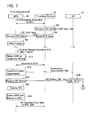
- the contents of processes performed by the devices 10, 70 will be described with reference to Figs. 2 to 4 .
- the user performs a setting change operation in the multi-function device 10 to change to the infrastructure wireless setting. That is, an example will be described where the user performs the setting change operation for changing to a state where the wireless communication can be performed not just between the multi-function device 10 and the telephone device 70, but also between the multi-function device 10 and the PCs 4, 5.
- a shipment stage (can also be termed “initial state") of the multi-function device 10 and telephone device 70
- same wireless setting information WS1 (described in short as “WS1” below) is stored in advance in both the permanent setting area 38 of the multi-function device 10 and the permanent setting area 92 of the telephone device 70. That is, in the shipment stage, WS1 is set in both the multi-function device 10 and the telephone device 70.
- WS1 is the wireless setting information for the multi-function device 10 and the telephone device 70 to wirelessly communicate directly, not via the AP 6. That is, WS1 is ad-hoc wireless setting information. Consequently, as shown in Fig.
- a wireless connection according to WS1 (the ad-hoc wireless connection) is established between the multi-function device 10 and the telephone device 70.
- the multi-function device 10 and the telephone device 70 can wirelessly communicate the FAX data.
- the control unit 80 of the telephone device 70 receives FAX data 100 via the PSTN interface 76 (S2).
- the control unit 80 sends the FAX data 100 to the multi-function device 10 by utilizing the wireless connection according to WS1 (S4).
- the communication unit 52 of the multi-function device 10 thereby receives the FAX data 100 utilizing the wireless connection according to WS1 1 (S6).
- the print control unit 62 of the multi-function device 10 makes the print performing unit 16 print using the FAX data 100 (S8).
- a print medium on which an image represented by the FAX data 100 is formed can thereby be presented to the user.
- the FAX data 100 is sent from the telephone device 70 to the multi-function device 10 (i.e., an example of the FAX receiving operation from the PSTN 8).
- the FAX data i.e., the FAX data generated by the scan performing unit 18
- the FAX sending operation to the PSTN 8 can also be performed.
- the user By performing the setting change operation on the operation unit 12 of the multi-function device 10, the user inputs an instruction to the multi-function device 10 to change WS1 stored in the permanent setting area 38 to differing wireless setting information WS2 (described in short as “WS2" below) (S10).
- the setting change operation includes operations for inputting all types of information (authentication method, encryption method, password, etc.) included in WS2.
- WS2 is the wireless setting information for the multi-function device 10 and the telephone device 70 to wirelessly communicate indirectly via the AP 6. That is, WS2 is the infrastructure wireless setting information.
- the setting unit 56 stores WS2 in the temporary setting area 42 while WS1 is in a state of being maintained in the permanent setting area 38 (S12). In S12, further, the setting unit 56 determines that the wireless connection must be established using WS2 stored in the temporary setting area 42 instead of WS1 stored in the permanent setting area 38. The wireless connection according to WS1 between the multi-function device 10 and the telephone device 70 is thereby disconnected (S14). Next, the trying unit 58 wirelessly sends a connection requirement 102 to the AP 6 to establish a wireless connection with the AP 6 according to WS2 (S16).
- the connection requirement 102 includes information (authentication method, encryption method, authentication data needed for authentication, etc.) based on WS2.
- the AP 6 Upon receiving the connection requirement 102, the AP 6 performs authentication based on the connection requirement 102 (S18).
- This authentication includes, e.g., authentication concerning whether the authentication method and encryption method included in WS2 are supported by the AP 6, authentication concerning whether the password included in WS2 is registered in the AP 6, etc. Consequently, in order for the authentication of S18 to succeed, the user must input an authentication method and encryption method supported by the AP 6 when performing the operation of S10. Further, in order for the authentication of S 18 to succeed, the user must register a specific password in advance in the AP 6 before performing the operation of S10, and must input the same password as the specific password when performing the operation of S10.
- the AP 6 wirelessly sends to the multi-function device 10 an NG notice 104 indicating that the authentication has failed.
- Examples of the authentication of S 18 failing are the user failing to input the authentication method and encryption method supported by the AP 6 when performing the operation of S10, the user inputting a password different from the specific password registered in advance in the AP 6, etc.
- the setting unit 56 receives the NG notice 104 (S20).
- the control unit 50 of the multi-function device 10 displays a screen on the display unit 14 indicating that the setting cannot be changed (S22).
- the setting unit 56 deletes WS2 stored in the temporary setting area 42, and determines that the wireless connection according to WS1 must be re-established (S24).
- the multi-function device 10 maintains WS1 without changing the setting from WS1 to WS2, and the telephone device 70 also maintains WS1.
- the wireless connection according to WS1 is thereby re-established between the multi-function device 10 and the telephone device 70 (S26).
- the AP 6 cannot receive the connection requirement 102 in a case where e.g., a power of the AP 6 is OFF when the multi-function device 10 sends the connection requirement 102 in S 16. Further, the AP 6 also cannot receive the connection requirement 102 in a case where e.g., a distance between the AP 6 and multi-function device 10 is large. In these cases, the AP 6 cannot perform the authentication of S18, and does not send information indicating an authentication result (the NG notice 104, or an OK notice 110 of Fig. 3 (to be described)) to the multi-function device 10. In such circumstances, the multi-function device 10 and the telephone device 70 cannot communicate wirelessly via the AP 6 even though the setting was changed from WS1 to WS2. Consequently, although not shown, in the case of not receiving the NG notice 104 or the OK notice 110 even though a predetermined time has elapsed since the connection requirement 102 was sent in S16, the setting unit 56 performs the processes S22 to S26.
- the AP 6 wirelessly sends the OK notice 110 indicating that authentication has succeeded to the multi-function device 10.
- the setting unit 56 thereby receives the OK notice 110 (S32).
- a wireless connection according to WS2 is established between the multi-function device 10 and the AP 6 (S34).
- the setting unit 56 determines that the wireless connection according to WS1 must be re-established instead of the wireless connection according to WS2 (S40).
- the wireless connection according to WS2 established between the multi-function device 10 and the AP 6 is thereby disconnected (S42).
- the wireless connection according to WS1 is re-established between the multi-function device 10 and the telephone device 70 (S44).
- the first sending unit 54 sends WS2 to the telephone device 70 using the re-established wireless connection according to WS1 (S46).
- the control unit 80 of the telephone device 70 thereby receives WS2 (S48).
- the control unit 80 of the telephone device 70 Upon receiving WS2, the control unit 80 of the telephone device 70 stores (reflects) WS2 in the temporary setting area 94 while WS1 is in the state of being maintained in the permanent setting area 92 (S50). In S50, further, the control unit 80 determines that the wireless connection must be established using WS2 stored in the temporary setting area 94 instead of WS1 stored in the permanent setting area 92. The wireless connection according to WS1 is thereby disconnected (S52). Next, the control unit 80 of the telephone device 70 wirelessly sends, to the AP 6, a connection requirement 112 that includes information based on WS2 in order to establish a wireless connection according to WS2 with the AP 6 (S54).
- the AP 6 Upon receiving the connection requirement 112, the AP 6 performs authentication based on the connection requirement 112 (S56). This authentication is the same as that of S 18 of Fig. 2 . Consequently, in the case where the authentication of S18 succeeds, the authentication of S56 usually succeeds. However, e.g., in the case where information for inhibiting the establishment of the wireless connection between the AP 6 and the telephone device 70 has been registered in advance in the AP 6 (e.g., a case where a MAC address of the telephone device 70 has been registered in advance in the AP 6 as a MAC address that inhibits the establishment of the wireless connection), the authentication of S56 may fail.
- the AP 6 wirelessly sends an NG notice 114 indicating the authentication has failed to the telephone device 70.
- the control unit 80 of the telephone device 70 thereby receives the NG notice 114 (S58).
- the control unit 80 deletes WS2 stored in the temporary setting area 94, and determines that the wireless connection according to WS1 must be re-established (S60).
- the wireless connection according to WS1 is thereby re-established between the multi-function device 10 and the telephone device 70 (S62).
- the control unit 80 sends an NG notice 116 indicating that the authentication has failed to the multi-function device 10 (S64).
- the setting unit 56 thereby receives the NG notice 116 (S66).
- control unit 50 of the multi-function device 10 displays a screen on the display unit 14 indicating that the setting cannot be changed (S68). Further, the setting unit 56 deletes WS2 stored in the temporary setting area 42 (S70). In this case, the multi-function device 10 maintains WS1 without changing the setting from WS1 to WS2, and the telephone device 70 also maintains WS1.
- the AP 6 cannot receive the connection requirement 112 in a case where the power of the AP 6 is ON when the multi-function device 10 sends the connection requirement 102 in S 16 of Fig. 2 , but the power of the AP 6 is OFF when the telephone device 70 sends the connection requirement 112 in S54 of Fig. 3 . Further, the AP 6 also cannot receive the connection requirement 112 in a case where e.g., a distance between the AP 6 and the telephone device 70 is large. Although not shown, taking these cases into account, in the case of not receiving the NG notice 114 or an OK notice 120 (to be described) (see Fig. 4 ) even though a predetermined time has elapsed since the connection requirement 112 was sent in S54, the control unit 80 of the telephone device 70 performs the processes S60-S64.
- the AP 6 wirelessly sends the OK notice 120 indicating that the authentication has succeeded to the telephone device 70.
- the control unit 80 of the telephone device 70 thereby receives the OK notice 120 (S82).
- the wireless connection according to WS2 is established between the telephone device 70 and the AP 6 (S84).
- the control unit 80 determines that the wireless connection according to WS1 must be re-established instead of the wireless connection according to WS2 (S86).
- the wireless connection according to WS2 established between the telephone device 70 and the AP 6 is thereby disconnected (S88). Further, the wireless connection according to WS1 is re-established between the multi-function device 10 and the telephone device 70 (S90).
- the control unit 80 sends a connection completion notice 122 to the multi-function device 10 indicating that the wireless connection with the AP 6 has been established (S92). Further, the control unit 80 deletes WS1 stored in the permanent setting area 92, and newly stores WS2 in the permanent setting area 92 (S96). The telephone device 70 thereby newly sets WS2 in the telephone device 70 as the wireless setting information for the telephone device 70 to wirelessly communicate FAX data. That is, the connection completion notice 122 sent in S92 is a notice sent when the setting of the telephone device 70 changes from WS1 to WS2.
- the setting unit 56 of the multi-function device 10 receives the connection completion notice 122 from the telephone device 70 (S94). In this case, the setting unit 56 deletes WS1 stored in the permanent setting area 38, and newly stores WS2 in the permanent setting area 38 (S98). The multi-function device 10 thereby newly sets WS2 in the multi-function device 10 as the wireless setting information for the multi-function device 10 to wirelessly communicate FAX data.
- the wireless connection according to WS1 is disconnected (S99).
- the trying unit 58 wirelessly sends a connection requirement 124 that includes information based on WS2 to the AP 6 in order to establish a wireless connection according to WS2 with the AP 6 (S100). Since the authentication of S18 of Fig. 2 has been successful once, the AP 6 usually wirelessly sends an OK notice 126 to the multi-function device 10.
- the setting unit 56 thereby receives the OK notice 126 (S102).
- the wireless connection according to WS2 is thereby established between the multi-function device 10 and the AP 6 (S104).
- the control unit 50 of the multi-function device 10 displays a screen on the display unit 14 indicating that the wireless connection with the AP 6 has been established (S106).
- control unit 80 of the telephone device 70 wirelessly sends, to the AP 6, a connection requirement 128 that includes information based on WS2 in order to establish a wireless connection with the AP 6 according to WS2 (S108). Since the authentication of S56 of Fig. 3 has been successful once, the AP 6 usually wirelessly sends an OK notice 130 to the telephone device 70. The control unit 80 thereby receives the OK notice 130 (S110). The wireless connection according to WS2 is thereby established between the telephone device 70 and the AP 6 (S112).
- the wireless connection according to WS2 is established between the multi-function device 10 and the AP 6 (S104), and the wireless connection according to WS2 is established between the telephone device 70 and the AP 6 (S112).
- the multi-function device 10 and the telephone device 70 can wirelessly communicate FAX data via the AP 6.
- the control unit 80 of the telephone device 70 receives FAX data 140 via the PSTN interface 76 (S114).
- the control unit 80 sends the FAX data 140 to the multi-function device 10 via the AP 6 (S116).
- the communication unit 52 thereby receives the FAX data 140 (S 118).
- the print control unit 62 makes the print performing unit 16 print (S120).
- S120 the print performing unit 16 print
- Fig. 4 an example was described of an operation of receiving a FAX from the PSTN 8.
- an operation of sending a FAX to the PSTN 8 can also be performed.
- the wireless communication system 2 of the first embodiment has been described in detail.
- a configuration may be considered in which the multi-function device 10 changes the wireless setting information for wirelessly communicating the FAX data (the wireless setting information within the permanent setting area 38) from WS1 to WS2 (termed “comparative example configuration" below) after the multi-function device 10 has sent WS2 to the telephone device 70 (after S46 of Fig. 3 ), regardless of whether the connection completion notice 122 of Fig. 4 is received.
- the phenomenon where the multi-function device 10 changes the setting from WS1 to WS2, but the telephone device 70 maintains WS1 without changing the setting may occur (e.g., in the case where the NG notice 114 of Fig.
- the multi-function device 10 and the telephone device 70 cannot communicate the FAX data wirelessly. That is, the FAX receiving operation and the FAX sending operation cannot be realized.
- the telephone device 70 changes the wireless setting information for wirelessly communicating the FAX data (the wireless setting information within the permanent setting area 92) from WS1 to WS2, the telephone device 70 sends the connection completion notice 122 to the multi-function device 10 (S92 of Fig. 4 ).
- the multi-function device 10 changes the setting from WS1 to WS2 (S98 of Fig. 4 ).
- the multi-function device 10 maintains WS1 without changing the setting from WS1 to WS2. It is thereby possible to inhibit differing wireless setting information being set in the multi-function device 10 and the telephone device 70. Consequently, compared to the comparative example configuration, the occurrence of the phenomenon where the multi-function device 10 and the telephone device 70 cannot wirelessly communicate the FAX data can be inhibited.
- the setting of the telephone device 70 is also changed from WS1 to WS2 (S96, S98 of Fig. 4 ). That is, the user can change the setting of the telephone device 70 without even performing the setting change operation on the telephone device 70. Even if an operability of the telephone device 70 is inferior due to reasons such as a display unit (not shown) of the telephone device 70 being smaller than the display unit 14 of the multi-function device 10, etc., the user can change the setting of the telephone device 70 using a user interface which is easier to perform setting (i.e., the user interface of the multi-function device 10).
- the multi-function device 10 Before the setting of the multi-function device 10 is changed from WS1 to WS2, the multi-function device 10 tries to establish a wireless connection with the AP 6 according to WS2 (S16 of Fig. 2 ). In the case of receiving the OK notice 110 of Fig. 3 from the AP 6, and of receiving the connection completion notice 122, the setting of the multi-function device 10 is changed from WS1 to WS2. In the case where the establishment of the wireless connection according to WS2 between the multi-function device 10 and the AP 6 is confirmed, it is possible to effectively inhibit the occurrence of the phenomenon where the multi-function device 10 and the telephone device 70 cannot wirelessly communicate the FAX data due to the setting thereof having been changed from WS1 to WS2.
- the multi-function device 10 does not perform the process S46 of Fig. 3 for sending WS2 to the telephone device 70. Consequently, since the telephone device 70 does not receive WS2, the telephone device 70 maintains WS1 without changing the setting from WS1 to WS2. In this case, since the multi-function device 10 also maintains WS1, the multi-function device 10 and the telephone device 70 can wirelessly communicate the FAX data utilizing the wireless connection according to WS1.
- the telephone device 70 before changing the setting from WS1 to WS2, the telephone device 70 tries to establish a wireless connection according to WS2 with the AP 6 (S54 of Fig. 3 ). Upon receiving the OK notice 120 of Fig. 4 from the AP 6, the telephone device 70 sends the connection completion notice 122 of Fig. 4 to the multi-function device 10. According to this configuration, in the case where the establishment of the wireless connection according to WS2 between the telephone device 70 and the AP 6 is confirmed, the multi-function device 10 can change the setting from WS1 to WS2.
- the multi-function device 10 and the telephone device 70 are respectively an example of a "first wireless communication device” and a “second wireless communication device”.
- WS1, WS2 are respectively an example of "first wireless setting information” and “second wireless setting information”.
- the FAX data 100, 140 are examples of "specific data”.
- the connection completion notice 122 of Fig. 4 is an example of a "predetermined signal”.
- the OK notice 110 of Fig. 3 , and the OK notice 120 of Fig. 4 are respectively an example of "success information" received by the first wireless communication device, and "success information" received by the second wireless communication device.
- the wireless connection according to WS1 is established between the multi-function device 10 and the telephone device 70.
- the user inputs, to the multi-function device 10, the instruction to change WS1 stored in the permanent setting area 38 of the multi-function device 10 to WS2 (S210).
- the setting unit 56 stores WS2 in the temporary setting area 42, and determines that the wireless connection must be established using WS2 instead of WS1 (S212).
- the wireless connection according to WS1 between the multi-function device 10 and the telephone device 70 is thereby disconnected (S214).
- the trying unit 58 wirelessly sends, to the AP 6, a connection requirement 200 that includes information based on WS2 (S216).
- the AP 6 performs the same authentication as in the first embodiment and, in the case where authentication has succeeded, wirelessly sends an OK notice 202 to the multi-function device 10.
- the AP 6 wirelessly sends an NG notice to the multi-function device 10, as in the first embodiment.
- the process in the case of the multi-function device 10 receiving the NG notice (see S22-S26 of Fig. 2 ) is the same as in the first embodiment.
- the process in the case of the multi-function device 10 receiving neither the NG notice nor the OK notice 202 is also the same as in the first embodiment.
- the wireless connection according to WS2 is established between the multi-function device 10 and the sAP 6 (S234).
- the setting unit 56 determines that the wireless connection according to WS1 must be re-established instead of the wireless connection according to WS2 (S240).
- the wireless connection according to WS2 established between the multi-function device 10 and the AP 6 is thereby disconnected (S242).
- the wireless connection according to WS1 is re-established between the multi-function device 10 and the telephone device 70 (S244).
- the first sending unit 54 sends WS2 to the telephone device 70 (S246).
- the processes until S246 are approximately the same as those of the first embodiment. Below, points differing from the first embodiment will be described.
- the telephone device 70 cannot receive WS2 e.g. in the case where the power of the telephone device 70 is OFF when WS2 is sent from the multi-function device 10 to the telephone device 70 (when S246 is performed).
- the setting unit 56 monitors whether a response is received from the telephone device 70 until a predetermined time elapses since WS2 was sent in S246 (S250). In the case where a response is not received even though the predetermined time has elapsed, the control unit 50 displays the screen on the display unit 14 indicating that the setting cannot be changed (S252). Further, the setting unit 56 deletes WS2 stored in the temporary setting area 42 (S254). In this case, the multi-function device 10 maintains WS1 without changing the setting from WS1 to WS2, and the telephone device 70 also maintains WS 1.
- the control unit 80 of the telephone device 70 utilizes the wireless connection according to WS1 to send the multi-function device 10 a reception completion notice 212 indicating WS2 has been received (S292).
- the control unit 80 deletes WS1 stored in the permanent setting area 92, and newly stores WS2 in the permanent setting area 92 (S296).
- WS2 is thereby newly set in the telephone device 70 as the wireless setting information for the telephone device 70 to wirelessly communicate the FAX data. That is, the reception completion notice 212 sent in S292 is a notice sent when the telephone device 70 changes the setting from WS1 to WS2.
- the setting unit 56 of the multi-function device 10 receives the reception completion notice 212 from the telephone device 70 (S294). In this case, the setting unit 56 deletes WS1 stored in the permanent setting area 38, and newly stores WS2 in the permanent setting area 38 (S298). WS2 is thereby newly set in the multi-function device 10 as the wireless setting information for the multi-function device 10 to wirelessly communicate FAX data. Moreover, although not shown, after S296, the control unit 80 of the telephone device 70 performs the processes S108, S 110 of Fig. 4 , as in the first embodiment. The wireless connection according to WS2 is thereby established between the telephone device 70 and the AP 6.
- the trying unit 58 of the multi-function device 10 performs the processes S100, S102, S106 of Fig. 4 , as in the first embodiment.
- a wireless connection according to WS2 is thereby established between the multi-function device 10 and the AP 6. Consequently, the multi-function device 10 and the telephone device 70 reach the state of being able to wirelessly communicate the FAX data via the AP 6.
- the case is described, as an example, where the authentication succeeds when the telephone device 70 performs the connection requirement with the AP 6.
- the wireless communication system 2 of the second embodiment was described in detail.
- the telephone device 70 changes the wireless setting information for wirelessly communicating FAX data (the wireless setting information in the permanent setting area 92) from WS1 to WS2, the telephone device 70 sends the reception completion notice 212 to the multi-function device 10 (S292).
- the multi-function device 10 changes the setting from WS1 to WS2 (S298).
- the multi-function device 10 maintains WS1 without changing the setting from WS1 to WS2 (S254). It is thereby possible to inhibit differing wireless setting information being set in the multi-function device 10 and the telephone device 70.
- the multi-function device 10 changes the wireless setting information for wirelessly communicating the FAX data (the wireless setting information in the permanent setting area 38) from WS1 to WS2 after having sent WS2 to the telephone device 70 (after S246 of Fig. 5 ).
- the reception completion notice 212 is an example of the "predetermined signal”.
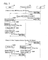
- a third embodiment will be described with reference to Fig. 6 and Fig. 7 .
- the description will focus upon points differing from the first and second embodiments.
- the wireless connection according to WS1 is established between the multi-function device 10 and the telephone device 70.
- the user inputs, to the multi-function device 10, the instruction to change WS1 stored in the permanent setting area 38 of the multi-function device 10 to WS2 (S310).
- the processes until S310 are approximately the same as in the first and second embodiments. Below, points differing from the first and second embodiments will be described.
- the first sending unit 54 sends WS2 to the telephone device 70 utilizing the wireless connection according to WS1 (S312).
- the multi-function device 10 maintains WS1 without changing the setting from WS1 to WS2 in the case where a response to sending WS2 is not received.
- the control unit 80 of the telephone device 70 receives WS2 (S314). Upon receiving WS2, the control unit 80 utilizes the wireless connection according to WS1 to send the multi-function device 10 a reception completion notice 302 indicating that WS2 has been received (S316). In this case, the control unit 80 stores WS2 in the temporary setting area 94, and determines that the wireless connection must be established using WS2 instead of WS1 (S322).
- the setting unit 56 of the multi-function device 10 receives the reception completion notice 302 (S318). In this case, the setting unit 56 stores WS2 in the temporary setting area 42, and determines that the wireless connection must be established using WS2 instead of WS1 (S320). The wireless connection according to WS1 between the multi-function device 10 and the telephone device 70 is thereby disconnected (S324).
- the trying unit 58 wirelessly sends, to the AP 6, a connection requirement 304 that includes information based on WS2 (S326).
- the AP 6 performs authentication identical to that of the first embodiment, and in the case of authentication succeeding, wirelessly sends an OK notice to the multi-function device 10.
- the control unit 80 of the telephone device 70 also wirelessly sends, to the AP 6, a connection requirement 306 that includes information based on WS2 (S328).
- the AP 6 performs authentication identical to that of the first embodiment, and in the case of the authentication succeeding, wirelessly sends an OK notice to the telephone device 70.
- pattern 6 shows processes performed in the case where both the multi-function device 10 and telephone device 70 receive the OK notice. Further, pattern 2 of Fig. 7 shows processes performed in the case where only the multi-function device 10 receives the OK notice, and pattern 3 shows processes performed in the case where only the telephone device 70 receives the OK notice.
- the wireless connection according to WS2 is established between the multi-function device 10 and the AP 6 (S340), and the wireless connection according to WS2 is established between the telephone device 70 and the AP 6 (S342).
- the second sending unit 60 of the multi-function device 10 sends the connection completion notice 310 to the telephone device 70 via the AP 6 utilizing the wireless connection according to WS2 (S344).
- the control unit 80 of the telephone device 70 thereby receives the connection completion notice 310 (S346).
- the control unit 80 sends a reception completion notice 312, indicating that the connection completion notice 310 has been received, to the multi-function device 10 via the AP 6 utilizing the wireless connection according to WS2 (S348). Further, the control unit 80 deletes WS1 stored in the permanent setting area 92, and newly stores WS2 in the permanent setting area 92 (S354). WS2 is thereby newly set in the telephone device 70 as the wireless setting information for the telephone device 70 to wirelessly communicate FAX data. That is, the reception completion notice 312 sent in S348 is a notice sent when the telephone device 70 changes the setting from WS1 to WS2.
- the setting unit 56 of the multi-function device 10 receives the reception completion notice 312 (S350). In this case, the setting unit 56 deletes WS1 stored in the permanent setting area 38, and newly stores WS2 in the permanent setting area 38 (S352). WS2 is thereby newly set in the multi-function device 10 as the wireless setting information for the multi-function device 10 to wirelessly communicate FAX data.
- the multi-function device 10 and the telephone device 70 can wirelessly communicate FAX data via the AP 6 utilizing the wireless connection according to WS2 established in S340 and S342.
- the wireless connection according to WS2 is established between the multi-function device 10 and the AP 6 (S360), but the wireless connection according to WS2 is not established between the telephone device 70 and the AP 6.
- the control unit 80 of the telephone device 70 deletes WS2 stored in the temporary setting area 94, and determines that the wireless connection must be established according to WS1 (S362).
- a wireless connection according to WS1 is not established between the multi-function device 10 and the telephone device 70. This is because the multi-function device 10 has established the wireless connection according to WS2 with the AP 6.
- the second sending unit 60 of the multi-function device 10 utilizes the wireless connection according to WS2 to send the connection completion notice 320 to the telephone device 70 via the AP 6 (S364).
- the telephone device 70 cannot receive the connection completion notice 320, and consequently does not send a reception completion notice to the multi-function device 10.
- the setting unit 56 monitors whether a response is received from the telephone device 70 until a predetermined time elapses since the connection completion notice 320 was sent in S364 (S366).
- the control unit 50 displays a screen on the display unit 14 indicating that the setting cannot be changed (S368). Further, the setting unit 56 deletes WS2 stored in the temporary setting area 42, and determines that the wireless connection according to WS1 must be re-established (S370). Thereby, in the case of pattern 2, the multi-function device 10 maintains WS1 without changing the setting from WS1 to WS2, and the telephone device 70 also maintains WS1. Consequently, the wireless connection according to WS1 is re-established between the multi-function device 10 and the telephone device 70 (S372).
- the wireless connection according to WS2 is established between the telephone device 70 and the AP 6 (S380), but the wireless connection according to WS2 is not established between the multi-function device 10 and the AP 6.
- the control unit 50 of the multi-function device 10 displays the screen on the display unit 14 indicating that the setting cannot be changed (S384).
- the setting unit 56 deletes WS2 stored in the temporary setting area 42, and determines that the wireless connection according to WS1 must be re-established (S386). However, at this point, a wireless connection according to WS1 is not established between the multi-function device 10 and the telephone device 70. This is because the telephone device 70 has established the wireless connection according to WS2 with the AP 6.
- the multi-function device 10 cannot send a connection completion notice to the telephone device 70 via the AP 6 utilizing a wireless connection according to WS2.
- the control unit 80 of the telephone device 70 monitors whether the connection completion notice is received from the multi-function device 10 until a predetermined time elapses since the OK notice was received from the AP 6 (S382).
- the control unit 80 deletes WS2 stored in the temporary setting area 94, and determines that the wireless connection according to WS1 must be re-established (S388).
- the multi-function device 10 maintains WS1 without changing the setting from WS1 to WS2, and the telephone device 70 also maintains WS1. Consequently, the wireless connection according to WS1 is re-established between the multi-function device 10 and the telephone device 70 (S390).
- a pattern can be obtained where neither the multi-function device 10 nor the telephone device 70 receives the OK notice.
- the setting unit 56 of the multi-function device 10 deletes WS2 stored in the temporary setting area 42, and determines that the wireless connection according to WS1 must be re-established (S386).
- the control unit 80 of the telephone device 70 deletes WS2 stored in the temporary setting area 94, and determines that the wireless connection according to WS1 must be re-established (S362).
- the multi-function device 10 maintains WS1 without changing the setting from WS1 to WS2, and the telephone device 70 also maintains WS 1. Consequently, the wireless connection according to WS1 is re-established between the multi-function device 10 and the telephone device 70.
- the wireless communication system 2 of the third embodiment was described in detail.
- the telephone device 70 when changing the wireless setting information for wirelessly communicating FAX data (the wireless setting information in the permanent setting area 92) from WS1 to WS2, the telephone device 70 sends the reception completion notice 312 to the multi-fimction device 10 (S348 of Fig. 6 ).
- the multi-function device 10 changes the setting from WS1 to WS2 (S352 of Fig. 6 ).
- the multi-function device 10 maintains WS1 without changing the setting from WS1 to WS2.
- the telephone device 70 also maintains WS1. It is thereby possible to inhibit differing wireless setting information to be set in the multi-function device 10 and telephone device 70. Consequently, occurrence of the phenomenon where the multi-function device 10 and the telephone device 70 cannot wirelessly communicate FAX data can be inhibited compared to the configuration where, regardless of whether the reception completion notice 312 of Fig. 6 is received, the multi-function device 10 changes the wireless setting information for wirelessly communicating the FAX data (the wireless setting information in the permanent setting area 38) from WS1 to WS2.
- the multi-function device 10 receives the reception completion notice 312 from the telephone device 70 via the AP 6 utilizing the wireless connection according to WS2.
- the multi-function device 10 receiving the reception completion notice 312 means that the multi-function device 10 and the telephone device 70 can wirelessly communicate according to WS2. That is, according to the present embodiment, the setting can be changed from WS1 to WS2 in the multi-function device 10 in the case where it is confirmed that the multi-function device 10 and the telephone device 70 can wirelessly communicate according to WS2.
- the reception completion notice 312 is an example of the "predetermined signal”.
- the connection completion notice 310 is an example of the "specific signal”.
- the multi-function device 10 upon receiving the OK notice from the AP 6, the multi-function device 10 sends the connection completion notice 310 to the telephone device 70 and, upon the telephone device 70 receiving the connection completion notice 310, the telephone device 70 sends the reception completion notice 312 to the multi-function device 10.
- a configuration opposite to that of the third embodiment is adopted. That is, in the case of the control unit 80 of the telephone device 70 receiving the OK notice from the AP 6, the control unit 80 of the telephone device 70 utilizes the wireless connection according to WS2 to send the connection completion notice to the telephone device 70 via the AP 6.
- the second sending unit 60 of the multi-function device 10 Upon receiving the connection completion notice, the second sending unit 60 of the multi-function device 10 utilizes the wireless connection according to WS2 to send the reception completion notice to the telephone device 70 via the AP 6.
- the setting unit 56 of the multi-function device 10 In the case of the setting unit 56 of the multi-function device 10 receiving the connection completion notice from the telephone device 70, the setting unit 56 of the multi-function device 10 deletes WS1 stored in the permanent setting area 38, and newly stores WS2 in the permanent setting area 38. WS2 is thereby newly set in the multi-function device 10 as the wireless setting information for the multi-function device 10 to wirelessly communicate FAX data. Further, in the case of the control unit 80 of the telephone device 70 receiving the reception completion notice from the multi-function device 10, the control unit 80 of the telephone device 70 deletes WS1 stored in the permanent setting area 92, and newly stores WS2 in the permanent setting area 92. WS2 is thereby newly set in the telephone device 70 as the wireless setting information for the telephone device 70 to wirelessly communicate FAX data. In the present variant, the connection completion notice sent from the telephone device 70 to the multi-function device 10 is an example of the "predetermined signal".
- the aforementioned embodiments teach examples in which the setting is changed from the ad-hoc wireless setting information WS1 to the infrastructure wireless setting information WS2.
- the technique of the aforementioned embodiments can also be applied to a configuration in which the setting is changed from the infrastructure wireless setting information WS2 to the ad-hoc wireless setting information WS1.
- the technique can also be applied to a configuration in which the setting is changed from the infrastructure wireless setting information WS2 to infrastructure wireless setting information WS3.
- the technique of the aforementioned embodiments can also be applied to a case of changing the setting from the ad-hoc wireless setting information WS1 to ad-hoc wireless setting information WS4.
- a process of trying to wirelessly connect with the AP 6 is not performed. That is, in the case where the telephone device 70 receives WS1, the telephone device 70 may send the reception completion notice to the multi-function device 10, and change the setting from WS2 to WS1. In the case where the multi-function device 10 receives the reception completion notice, the multi-function device 10 may change its setting from WS2 to WS1.
- the telephone device 70 may send a reception completion notice to the multi-function device 10, and change its setting from WS1 to WS4.
- the multi-function device 10 may change its setting from WS1 to WS4.
- the reception completion notice sent from the telephone device 70 to the multi-function device 10 is an example of the "predetermined signal".
- the target data communicated between the multi-function device 10 and the telephone device 70 is FAX data. That is, generally speaking, the FAX data is an example of the "specific data". However, the "specific data" is not restricted to FAX data, and may be sound data (e.g., sound data of an answering machine), image data other than FAX data communicated via the PSTN 8, or other data (e.g., text data).
- the setting change operation for inputting WS2 is performed in S10 of Fig. 2 , S210 of Fig. 5 , and S310 of Fig. 6 via the operation unit 12 of the multi-function device 10.
- the setting change operation for inputting WS2 may be performed via an operation unit of a specific PC (not shown) connected with the wired LAN.
- the specific PC may send WS2 to the multi-function device 10 via the wired LAN.
- the multi-function device 10 may determine that the instruction to change WS1 to WS2 has been input.
- the telephone device 70 changes its setting from WS1 to WS2 (S96). Instead of this configuration, the telephone device 70 may first perform the process S96, and then perform the process S92. Similarly, in the second embodiment, the telephone device 70 may first perform the process S296 of Fig. 5 , and then perform the process S292. Similarly, in the third embodiment, the telephone device 70 may first perform the process S354 of Fig. 6 , and then perform the process S348.
- the "predetermined signal” may be sent to the first wireless communication device by the second wireless communication device before the second wireless communication device changes the first wireless setting information to the second wireless setting information, and may be sent to the first wireless communication device after the second wireless communication device has changed the first wireless setting information to the second wireless setting information.
- the telephone device 70 may send the reception completion notice to the multi-function device 10.
- the multi-function device 10 may perform the process to store WS2 in the permanent setting area 38 (the process S98 of Fig. 4 ).
- the multi-function device 10 need not perform the process to store WS2 in the permanent setting area 38 (the process S98 of Fig. 4 ).
- the case was described as an example where the telephone device 70 is an attachment device of the multi-function device 10, but the embodiments are not limited to this.
- a PC may be utilized instead of the telephone device 70.
- the user may perform the setting change operation in the multi-function device 10.
- the multi-function device 10 and the PC may perform the processes of the aforementioned embodiments, and may change the settings.
- print data for the PC to instruct the multi-function device 10 to perform printing is an example of the "specific data".
- respective units 52 to 62 are realized as a result of the control device 50 performing the processes according to the program 34. Nevertheless, at least one unit of respective units 52 to 62 may alternately be realized by a hardware resource such as a logic circuit.
Landscapes
- Engineering & Computer Science (AREA)
- Computer Networks & Wireless Communication (AREA)
- Signal Processing (AREA)
- Mobile Radio Communication Systems (AREA)
Abstract
Description
- The present specification teaches a wireless communication device that communicates wirelessly with another wireless communication device.
- A wireless telephone that communicates wirelessly between a base unit and a handset is known (e.g., Japanese patent application publication No.
H6-69870 - In both the ad-hoc wireless communication technique and the infrastructure wireless communication technique, the same wireless setting information (e.g., authentication method, encryption method, etc.) must be set in each of the pair of wireless communication devices for the pair of wireless communication devices to properly communicate wirelessly. That is, in a state where differing wireless setting information has been set in the pair of wireless communication devices, the pair of wireless communication devices cannot properly communicate wirelessly. In the present specification, a technique is disclosed for inhibiting an occurrence of a phenomenon where a pair of wireless communication devices cannot properly communicate wirelessly.
- One technique disclosed in the present application is a first wireless communication device configured to be wirelessly connected with a second wireless communication device. The first wireless communication device may comprise a communication unit, a first sending unit, and a setting unit. The communication unit may be configured to communicate specific data with the second wireless communication device by utilizing a wireless connection according to wireless communication setting information for communicating the specific data. The first sending unit may be configured to send second wireless setting information to the second wireless communication device by utilizing a first wireless connection according to first wireless setting information in a case where an instruction is input, the instruction being for changing the first wireless setting information currently being set in the first wireless communication device as the wireless setting information for communicating the specific data to the second wireless setting information. The setting unit may be configured to newly set the second wireless setting information as the wireless setting information for communicating the specific data in a case where a predetermined signal is received, the predetermined signal sent from the second wireless communication device to the first wireless communication device when the second wireless communication device changes the first wireless setting information currently being set in the second wireless communication device to the second wireless setting information. The setting unit may be configured to maintain the first wireless setting information as the wireless setting information for communicating the specific data in a case where the predetermined signal is not received.
- The following problem could occur if a configuration (termed "specific configuration" below) is adopted, regardless of whether the predetermined signal is received, the setting is changed from the first wireless setting information to the second wireless setting information after the first wireless communication device has sent the second wireless setting information to the second wireless communication device. In a state where the first wireless communication device does not receive the predetermined signal, it is not guaranteed that the second wireless communication device will properly change the setting from the first wireless setting information to the second wireless setting information. Consequently, in the aforementioned specific configuration, the phenomenon where the first wireless communication device may change the setting to the second wireless setting information, but the second wireless communication device may not change the setting, and may maintain the first wireless setting information can occur. In this case, differing wireless setting information is set in the first and second wireless communication devices, and consequently the first and second wireless communication devices cannot communicate the specific data wirelessly. To deal with this, the first wireless communication device disclosed in the present specification changes the setting to the second wireless setting information in the case where the predetermined signal is received, i.e., in the case where it has been confirmed that the second wireless communication device has changed its setting to the second wireless setting information. On the other hand, the first wireless communication device maintains the first wireless setting information in the case where it does not receive the predetermined signal, i.e., in the case where it has not been confirmed that the second wireless communication device has changed its setting to the second wireless setting information. Thus, it is possible to inhibit differing wireless setting information being set in the first and second wireless communication devices. Consequently, the phenomenon where the first and second wireless communication devices cannot communicate the specific data wirelessly can be inhibited better than in the aforementioned specific configuration.
- The first wireless communication device may further comprise a trying unit configured to perform trying to establish, in place of the first wireless connection, a second wireless connection according to the second wireless setting information between the first wireless communication device and an access point in a case where the second wireless setting information is wireless setting information for wirelessly communicating via the access point. The setting unit may newly set the second wireless setting information as the wireless setting information for communicating the specific data in a case where success information indicating that the trying has succeeded is received from the access point and the predetermined signal is received. If the second wireless connection is not properly established between the first wireless communication device and the access point even though the same second wireless setting information is set in the first and second wireless communication devices, the first and second wireless communication devices cannot communicate the specific data wirelessly via the access point. In order to inhibit occurrence of such a phenomenon, in the aforementioned technique, the first wireless communication device changes the setting to the second wireless setting information in the case of receiving the success information from the access point, i.e., in the case where it is confirmed that the second wireless connection has been established between the first wireless communication device and the access point. According to this configuration, the phenomenon where the first and second wireless communication devices cannot wirelessly communicate the specific data can be inhibited more effectively.
- The first sending unit may not send the second wireless setting information to the second wireless communication device in a case where the success information is not received from the access point even if the instruction is input. According to this configuration, in the case where the success information is not received from the access point, the first wireless communication device does not send the second wireless setting information to the second wireless communication device, and consequently the second wireless communication device maintains the first wireless setting information without changing the setting to the second wireless setting information. Consequently, the second wireless communication device does not send the predetermined signal to the first wireless communication device, and therefore the first wireless communication device also maintains the first wireless setting information without changing the setting to the second wireless setting information. The first and second wireless communication devices communicate the specific data wirelessly utilizing the first wireless connection according to the first wireless setting information.
- In a case where the success information is received from the access point, the first sending unit may re-establish the first wireless connection in place of the second wireless connection which had been established in the trying, and may send the second wireless setting information to the second wireless communication device by utilizing the first wireless connection which has been re-established.
- The setting unit may receive the predetermined signal from the second wireless communication device by utilizing the first wireless connection which has been re-established.
- The predetermined signal may be a signal sent from the second wireless communication device to the first wireless communication device when the second wireless communication device receives the success information from the access point in a case where the second wireless communication device performs trying to establish a wireless connection according to the second wireless setting information between the second wireless communication device and the access point. According to this configuration, the first wireless communication device can change the setting in the case where it is confirmed that the wireless connection has been established between the second wireless communication device and the access point.
- The predetermined signal may be a signal sent from the second wireless communication device to the first wireless communication device when the second wireless communication device receives the second wireless setting information.
- The setting unit may receive the predetermined signal from the second wireless communication device via the access point by utilizing the second wireless connection which has been established in the trying. In this configuration, the first wireless communication device receiving the predetermined signal means that the first and second wireless communication devices can communicate wirelessly according to the second wireless setting information. That is, according to this configuration, the first wireless communication device can change the setting in the case where it is confirmed that the first and second wireless communication devices can communicate wirelessly according to the second wireless setting information.
- The first wireless communication device may further comprise a second sending unit configured to send, in a case where the success information is received from the access point, a specific signal to the second wireless communication device via the access point by utilizing the second wireless connection which has been established in the trying. The predetermined signal may be a signal sent from the second wireless communication device to the first wireless communication device via the access point when the second wireless communication device receives the specific signal.
- The predetermined signal may be a signal sent from the second wireless communication device to the first wireless communication device via the access point when the second wireless communication device receives the success information from the access point in a case where the second wireless communication device performs trying to establish a wireless connection according to the second wireless setting information between the second wireless communication device and the access point.
- The second wireless communication device may be an attachment device of the first wireless communication device. The first wireless setting information may be wireless setting information of an ad-hoc mode for the first wireless communication device and the second wireless communication device wirelessly communicating directly not via the access point.
- The first wireless communication device may further comprise a print control unit configured to make a print performing unit print by utilizing the specific data in a case where the communication device receives the specific data from the second wireless communication device by utilizing the wireless connection according to the wireless communication setting information for communicating the specific data.
- Moreover, the first wireless communication device is novel and has utility as a single unit. The second wireless communication device is also novel and has utility as a single unit. Further, a control method, computer program, and non-transitory computer readable storage medium storing the computer program for realizing the first wireless communication device are also novel and have utility. A control method, computer program, and non-transitory computer readable storage medium storing the computer program for realizing the second wireless communication device are novel and have utility. Further, a wireless communication system provided with the first wireless communication device and the second wireless communication device is novel and has utility.
-
-
Fig. 1 shows a configuration of a wireless communication system of embodiments; -
Fig. 2 shows a sequence view of processes performed by devices of a first embodiment; -
Fig. 3 shows the sequence view continuing fromFig. 2 ; -
Fig. 4 shows the sequence view continuing fromFig. 3 ; -
Fig. 5 shows a sequence view of processes performed by devices of a second embodiment; -
Fig. 6 shows a sequence view of processes performed by devices of a third embodiment; and -
Fig. 7 shows a sequence view of processes performed by devices of the third embodiment. - The first embodiment will be described with reference to the figures. As shown in
Fig. 1 , awireless communication system 2 comprises a plurality ofPCs multi-function device 10, and atelephone device 70. The PC 4 and the PC 5 can wirelessly communicate with one another via the AP 6. Themulti-function device 10 and thetelephone device 70 can wirelessly communicate with one another either via the AP 6 or not via the AP 6. That is, themulti-function device 10 and thetelephone device 70 can perform an infrastructure wireless communication or ad-hoc wireless communication. Moreover, in the present embodiment, the wireless communication is performed based on the standards 802.11 of the IEEE (The Institute of Electrical and Electronics Engineers, Inc.), and standards conforming thereto (802.11a, 11b, etc.). Consequently, wireless setting information WS1, WS2 (to be described) is wireless setting information conforming to those standards. - The configuration of the
multi-function device 10 will be described in detail. Themulti-function device 10 is capable of performing multiple functions, such as print function, scanner function, copy function, etc. Themulti-function device 10 comprises anoperation unit 12, adisplay unit 14, aprint performing unit 16, ascan performing unit 18, awireless interface 20, awired interface 22, astorage unit 30, and acontrol unit 50. Theoperation unit 12 comprises a plurality of keys. A user can input various instructions to themulti-function device 10 by operating theoperation unit 12. Thedisplay unit 14 is a display for displaying various types of information. Theprint performing unit 16 is a printing mechanism, such as an ink jet method, laser method, etc. Thescan performing unit 18 is a scanning mechanism, such as CCD, CIS, etc. Thewireless interface 20 is an interface for performing wireless communication. Thewired interface 22 is an interface for performing wired communication. - The
storage unit 30 comprises aROM 32, a NVRAM (non-volatile memory) 36, and a VRAM (volatile memory) 40. TheROM 32 stores aprogram 34 for thecontrol unit 50 to execute various processes. TheNVRAM 36 comprises apermanent setting area 38. Thepermanent setting area 38 stores wireless setting information for themulti-function device 10 to wirelessly communicate FAX data with thetelephone device 70. The wireless setting information includes authentication method, encryption method, password, etc. A state of specific wireless setting information being stored in thepermanent setting area 38 is a state of the specific wireless setting information being set in themulti-function device 10 as the wireless setting information for themulti-function device 10 to wirelessly communicate FAX data. TheVRAM 40 comprises atemporary setting area 42. Thetemporary setting area 42 temporarily stores an other wireless setting information while a process to change the setting of the wireless setting information stored in thepermanent setting area 38 to the other wireless setting information is being performed. - The
control unit 50 performs various processes according to theprogram 34 stored in theROM 32. Functions of acommunication unit 52, first sendingunit 54, settingunit 56, tryingunit 58, second sendingunit 60, andprint control unit 62 are realized by thecontrol unit 50 performing the processes according to theprogram 34. Thecommunication unit 52 performs sending and receiving of FAX data with thetelephone device 70. The first sendingunit 54 sends, to thetelephone device 70, wireless setting information based on various types of information (authentication method, encryption method, password, etc.) input by a setting change operation of the user. The settingunit 56 changes the wireless setting information currently being set in themulti-function device 10 to new wireless setting information, or maintains the wireless setting information currently being set in themulti-function device 10. The tryingunit 58 tries to perform wireless communication using the wireless setting information based on the setting change operation of the user. Thesecond sending unit 60 sends, via theAP 6, a connection completion notice (to be described) (aconnection completion notice 310 ofFig. 6 , aconnection completion notice 320 ofFig. 7 ) to thetelephone device 70. Theprint control unit 62 controls the operation of theprint performing unit 16. - The
telephone device 70 is an attachment device of themulti-function device 10. That is, thetelephone device 70 is not shipped as an individual unit, but is shipped together with themulti-function device 10. Thetelephone device 70 comprises amicrophone 72,speaker 74,PSTN interface 76,wireless interface 78,control unit 80, andstorage unit 90. ThePSTN interface 76 is connected with a PSTN (Public Switched Telephone Network) 8, which is a general public network. Thewireless interface 78 is an interface for performing wireless communication. Thecontrol unit 80 performs various processes according to a program (not shown) stored in thestorage unit 90. Thestorage unit 90 comprises a NVRAM (non-volatile memory) 91 and VRAM (volatile memory) 93. TheNVRAM 91 comprises apermanent setting area 92. Thepermanent setting area 92 stores wireless setting information for thetelephone device 70 to wirelessly communicate the FAX data to themulti-function device 10. A state of specific wireless setting information stored in thepermanent setting area 92 is a state where the specific wireless setting information is set in thetelephone device 70 as the wireless setting information for thetelephone device 70 to wirelessly communicate the FAX data. TheVRAM 93 comprises atemporary setting area 94. Thetemporary setting area 94 temporarily stores an other wireless setting information while a process to change the setting of the wireless setting information stored in thepermanent setting area 92 to the other wireless setting information is being performed. - The telephone function is realized by the
telephone device 70 performing a process. For example, using thetelephone device 70, the user of themulti-function device 10 and thetelephone device 70 can make a telephone call to an other telephone device connected with thePSTN 8. In this case, thetelephone device 70 sends sound data corresponding to sound input to themicrophone 72 to the other telephone device via thePSTN interface 76. Further, in the case where sound data sent from the other telephone device is received by thePSTN interface 76, thetelephone device 70 outputs sound corresponding to that sound data from thespeaker 74. - Further, the FAX function is realized by the
multi-function device 10 and thetelephone device 70 performing a process together. For example, in the case of thePSTN interface 76 receiving image data (i.e., FAX data), thetelephone device 70 wirelessly sends the image data to themulti-function device 10. In the case where the image data sent wirelessly from thetelephone device 70 is received by thewireless interface 20, themulti-function device 10 makes theprint performing unit 16 print according to the image data. The FAX receiving operation is thereby performed. Further, themulti-function device 10 wirelessly sends, to thetelephone device 70, image data (e.g., the FAX data) that was generated by thescan performing unit 18 performing scanning. In the case where the image data sent wirelessly from themulti-function device 10 is received by thewireless interface 78, thetelephone device 70 sends the image data to a destination within thePSTN 8 that was specified previously by the user. The FAX sending operation is thereby performed. - Next, the contents of processes performed by the
devices Figs. 2 to 4 . Moreover, in the present embodiment, an example will be described where, in the case where themulti-function device 10 and thetelephone device 70 are configured capable of performing the ad-hoc wireless communication, the user performs a setting change operation in themulti-function device 10 to change to the infrastructure wireless setting. That is, an example will be described where the user performs the setting change operation for changing to a state where the wireless communication can be performed not just between themulti-function device 10 and thetelephone device 70, but also between themulti-function device 10 and thePCs - In a shipment stage (can also be termed "initial state") of the
multi-function device 10 andtelephone device 70, same wireless setting information WS1 (described in short as "WS1" below) is stored in advance in both thepermanent setting area 38 of themulti-function device 10 and thepermanent setting area 92 of thetelephone device 70. That is, in the shipment stage, WS1 is set in both themulti-function device 10 and thetelephone device 70. WS1 is the wireless setting information for themulti-function device 10 and thetelephone device 70 to wirelessly communicate directly, not via theAP 6. That is, WS1 is ad-hoc wireless setting information. Consequently, as shown inFig. 2 , a wireless connection according to WS1 (the ad-hoc wireless connection) is established between themulti-function device 10 and thetelephone device 70. In the state where the wireless connection has been established according to WS1, themulti-function device 10 and thetelephone device 70 can wirelessly communicate the FAX data. - While the wireless connection remains established according to WS1, the
control unit 80 of thetelephone device 70 receivesFAX data 100 via the PSTN interface 76 (S2). In this case, thecontrol unit 80 sends theFAX data 100 to themulti-function device 10 by utilizing the wireless connection according to WS1 (S4). Thecommunication unit 52 of themulti-function device 10 thereby receives theFAX data 100 utilizing the wireless connection according to WS1 1 (S6). In this case, theprint control unit 62 of themulti-function device 10 makes theprint performing unit 16 print using the FAX data 100 (S8). A print medium on which an image represented by theFAX data 100 is formed can thereby be presented to the user. Moreover, inFig. 2 , an example is shown where theFAX data 100 is sent from thetelephone device 70 to the multi-function device 10 (i.e., an example of the FAX receiving operation from the PSTN 8). However, in the state where the wireless connection remains established according to WS1, the FAX data (i.e., the FAX data generated by the scan performing unit 18) can also be sent from themulti-function device 10 to thetelephone device 70. That is, the FAX sending operation to thePSTN 8 can also be performed. - By performing the setting change operation on the
operation unit 12 of themulti-function device 10, the user inputs an instruction to themulti-function device 10 to change WS1 stored in thepermanent setting area 38 to differing wireless setting information WS2 (described in short as "WS2" below) (S10). The setting change operation includes operations for inputting all types of information (authentication method, encryption method, password, etc.) included in WS2. In the present embodiment, WS2 is the wireless setting information for themulti-function device 10 and thetelephone device 70 to wirelessly communicate indirectly via theAP 6. That is, WS2 is the infrastructure wireless setting information. In the case where the aforementioned instruction is input, the settingunit 56 stores WS2 in thetemporary setting area 42 while WS1 is in a state of being maintained in the permanent setting area 38 (S12). In S12, further, the settingunit 56 determines that the wireless connection must be established using WS2 stored in thetemporary setting area 42 instead of WS1 stored in thepermanent setting area 38. The wireless connection according to WS1 between themulti-function device 10 and thetelephone device 70 is thereby disconnected (S14). Next, the tryingunit 58 wirelessly sends aconnection requirement 102 to theAP 6 to establish a wireless connection with theAP 6 according to WS2 (S16). Theconnection requirement 102 includes information (authentication method, encryption method, authentication data needed for authentication, etc.) based on WS2. - Upon receiving the
connection requirement 102, theAP 6 performs authentication based on the connection requirement 102 (S18). This authentication includes, e.g., authentication concerning whether the authentication method and encryption method included in WS2 are supported by theAP 6, authentication concerning whether the password included in WS2 is registered in theAP 6, etc. Consequently, in order for the authentication of S18 to succeed, the user must input an authentication method and encryption method supported by theAP 6 when performing the operation of S10. Further, in order for the authentication ofS 18 to succeed, the user must register a specific password in advance in theAP 6 before performing the operation of S10, and must input the same password as the specific password when performing the operation of S10. - In the case where the authentication of S18 has failed, the
AP 6 wirelessly sends to themulti-function device 10 anNG notice 104 indicating that the authentication has failed. Examples of the authentication ofS 18 failing are the user failing to input the authentication method and encryption method supported by theAP 6 when performing the operation of S10, the user inputting a password different from the specific password registered in advance in theAP 6, etc. The settingunit 56 receives the NG notice 104 (S20). In this case, thecontrol unit 50 of themulti-function device 10 displays a screen on thedisplay unit 14 indicating that the setting cannot be changed (S22). Next, the settingunit 56 deletes WS2 stored in thetemporary setting area 42, and determines that the wireless connection according to WS1 must be re-established (S24). In this case, themulti-function device 10 maintains WS1 without changing the setting from WS1 to WS2, and thetelephone device 70 also maintains WS1. The wireless connection according to WS1 is thereby re-established between themulti-function device 10 and the telephone device 70 (S26). - Moreover, the
AP 6 cannot receive theconnection requirement 102 in a case where e.g., a power of theAP 6 is OFF when themulti-function device 10 sends theconnection requirement 102 inS 16. Further, theAP 6 also cannot receive theconnection requirement 102 in a case where e.g., a distance between theAP 6 andmulti-function device 10 is large. In these cases, theAP 6 cannot perform the authentication of S18, and does not send information indicating an authentication result (theNG notice 104, or anOK notice 110 ofFig. 3 (to be described)) to themulti-function device 10. In such circumstances, themulti-function device 10 and thetelephone device 70 cannot communicate wirelessly via theAP 6 even though the setting was changed from WS1 to WS2. Consequently, although not shown, in the case of not receiving the NG notice 104 or theOK notice 110 even though a predetermined time has elapsed since theconnection requirement 102 was sent in S16, the settingunit 56 performs the processes S22 to S26. - In the case where the authentication of
S 18 has succeeded, as shown inFig. 3 , theAP 6 wirelessly sends theOK notice 110 indicating that authentication has succeeded to themulti-function device 10. The settingunit 56 thereby receives the OK notice 110 (S32). In this case, a wireless connection according to WS2 is established between themulti-function device 10 and the AP 6 (S34). Next, the settingunit 56 determines that the wireless connection according to WS1 must be re-established instead of the wireless connection according to WS2 (S40). The wireless connection according to WS2 established between themulti-function device 10 and theAP 6 is thereby disconnected (S42). Next, the wireless connection according to WS1 is re-established between themulti-function device 10 and the telephone device 70 (S44). Next, the first sendingunit 54 sends WS2 to thetelephone device 70 using the re-established wireless connection according to WS1 (S46). Thecontrol unit 80 of thetelephone device 70 thereby receives WS2 (S48). - Upon receiving WS2, the
control unit 80 of thetelephone device 70 stores (reflects) WS2 in thetemporary setting area 94 while WS1 is in the state of being maintained in the permanent setting area 92 (S50). In S50, further, thecontrol unit 80 determines that the wireless connection must be established using WS2 stored in thetemporary setting area 94 instead of WS1 stored in thepermanent setting area 92. The wireless connection according to WS1 is thereby disconnected (S52). Next, thecontrol unit 80 of thetelephone device 70 wirelessly sends, to theAP 6, aconnection requirement 112 that includes information based on WS2 in order to establish a wireless connection according to WS2 with the AP 6 (S54). - Upon receiving the
connection requirement 112, theAP 6 performs authentication based on the connection requirement 112 (S56). This authentication is the same as that ofS 18 ofFig. 2 . Consequently, in the case where the authentication of S18 succeeds, the authentication of S56 usually succeeds. However, e.g., in the case where information for inhibiting the establishment of the wireless connection between theAP 6 and thetelephone device 70 has been registered in advance in the AP 6 (e.g., a case where a MAC address of thetelephone device 70 has been registered in advance in theAP 6 as a MAC address that inhibits the establishment of the wireless connection), the authentication of S56 may fail. In this case, theAP 6 wirelessly sends anNG notice 114 indicating the authentication has failed to thetelephone device 70. Thecontrol unit 80 of thetelephone device 70 thereby receives the NG notice 114 (S58). In this case, thecontrol unit 80 deletes WS2 stored in thetemporary setting area 94, and determines that the wireless connection according to WS1 must be re-established (S60). The wireless connection according to WS1 is thereby re-established between themulti-function device 10 and the telephone device 70 (S62). Further, using the re-established wireless connection according to WS1, thecontrol unit 80 sends anNG notice 116 indicating that the authentication has failed to the multi-function device 10 (S64). The settingunit 56 thereby receives the NG notice 116 (S66). In this case, thecontrol unit 50 of themulti-function device 10 displays a screen on thedisplay unit 14 indicating that the setting cannot be changed (S68). Further, the settingunit 56 deletes WS2 stored in the temporary setting area 42 (S70). In this case, themulti-function device 10 maintains WS1 without changing the setting from WS1 to WS2, and thetelephone device 70 also maintains WS1. - Moreover, the
AP 6 cannot receive theconnection requirement 112 in a case where the power of theAP 6 is ON when themulti-function device 10 sends theconnection requirement 102 inS 16 ofFig. 2 , but the power of theAP 6 is OFF when thetelephone device 70 sends theconnection requirement 112 in S54 ofFig. 3 . Further, theAP 6 also cannot receive theconnection requirement 112 in a case where e.g., a distance between theAP 6 and thetelephone device 70 is large. Although not shown, taking these cases into account, in the case of not receiving the NG notice 114 or an OK notice 120 (to be described) (seeFig. 4 ) even though a predetermined time has elapsed since theconnection requirement 112 was sent in S54, thecontrol unit 80 of thetelephone device 70 performs the processes S60-S64. - In the case where the authentication of S56 has succeeded, as shown in
Fig. 4 , theAP 6 wirelessly sends theOK notice 120 indicating that the authentication has succeeded to thetelephone device 70. Thecontrol unit 80 of thetelephone device 70 thereby receives the OK notice 120 (S82). In this case, the wireless connection according to WS2 is established between thetelephone device 70 and the AP 6 (S84). Next, thecontrol unit 80 determines that the wireless connection according to WS1 must be re-established instead of the wireless connection according to WS2 (S86). The wireless connection according to WS2 established between thetelephone device 70 and theAP 6 is thereby disconnected (S88). Further, the wireless connection according to WS1 is re-established between themulti-function device 10 and the telephone device 70 (S90). Next, using the re-established wireless connection according to WS1, thecontrol unit 80 sends aconnection completion notice 122 to themulti-function device 10 indicating that the wireless connection with theAP 6 has been established (S92). Further, thecontrol unit 80 deletes WS1 stored in thepermanent setting area 92, and newly stores WS2 in the permanent setting area 92 (S96). Thetelephone device 70 thereby newly sets WS2 in thetelephone device 70 as the wireless setting information for thetelephone device 70 to wirelessly communicate FAX data. That is, theconnection completion notice 122 sent in S92 is a notice sent when the setting of thetelephone device 70 changes from WS1 to WS2. - The setting
unit 56 of themulti-function device 10 receives theconnection completion notice 122 from the telephone device 70 (S94). In this case, the settingunit 56 deletes WS1 stored in thepermanent setting area 38, and newly stores WS2 in the permanent setting area 38 (S98). Themulti-function device 10 thereby newly sets WS2 in themulti-function device 10 as the wireless setting information for themulti-function device 10 to wirelessly communicate FAX data. - When S96 and S98 end, the wireless connection according to WS1 is disconnected (S99). Next, the trying
unit 58 wirelessly sends aconnection requirement 124 that includes information based on WS2 to theAP 6 in order to establish a wireless connection according to WS2 with the AP 6 (S100). Since the authentication of S18 ofFig. 2 has been successful once, theAP 6 usually wirelessly sends anOK notice 126 to themulti-function device 10. The settingunit 56 thereby receives the OK notice 126 (S102). The wireless connection according to WS2 is thereby established between themulti-function device 10 and the AP 6 (S104). In this case, thecontrol unit 50 of themulti-function device 10 displays a screen on thedisplay unit 14 indicating that the wireless connection with theAP 6 has been established (S106). - Further, the
control unit 80 of thetelephone device 70 wirelessly sends, to theAP 6, aconnection requirement 128 that includes information based on WS2 in order to establish a wireless connection with theAP 6 according to WS2 (S108). Since the authentication of S56 ofFig. 3 has been successful once, theAP 6 usually wirelessly sends anOK notice 130 to thetelephone device 70. Thecontrol unit 80 thereby receives the OK notice 130 (S110). The wireless connection according to WS2 is thereby established between thetelephone device 70 and the AP 6 (S112). - As described above, the wireless connection according to WS2 is established between the
multi-function device 10 and the AP 6 (S104), and the wireless connection according to WS2 is established between thetelephone device 70 and the AP 6 (S112). In this state, themulti-function device 10 and thetelephone device 70 can wirelessly communicate FAX data via theAP 6. For example, thecontrol unit 80 of thetelephone device 70 receivesFAX data 140 via the PSTN interface 76 (S114). In this case, utilizing the wireless connection according to WS2, thecontrol unit 80 sends theFAX data 140 to themulti-function device 10 via the AP 6 (S116). Utilizing the wireless connection according to WS2, thecommunication unit 52 thereby receives the FAX data 140 (S 118). In this case, using theFAX data 140, theprint control unit 62 makes theprint performing unit 16 print (S120). Moreover, inFig. 4 , an example was described of an operation of receiving a FAX from thePSTN 8. However, in the state where the wireless connection according to WS2 has been established, an operation of sending a FAX to thePSTN 8 can also be performed. - The
wireless communication system 2 of the first embodiment has been described in detail. For example, a configuration may be considered in which themulti-function device 10 changes the wireless setting information for wirelessly communicating the FAX data (the wireless setting information within the permanent setting area 38) from WS1 to WS2 (termed "comparative example configuration" below) after themulti-function device 10 has sent WS2 to the telephone device 70 (after S46 ofFig. 3 ), regardless of whether theconnection completion notice 122 ofFig. 4 is received. In the above comparative example configuration, the phenomenon where themulti-function device 10 changes the setting from WS1 to WS2, but thetelephone device 70 maintains WS1 without changing the setting may occur (e.g., in the case where the NG notice 114 ofFig. 3 is received, or in the case where neither the NG notice 114 ofFig. 3 nor theOK notice 120 ofFig. 4 is received). In this case, since differing wireless setting information is set in themulti-function device 10 and thetelephone device 70, themulti-function device 10 and thetelephone device 70 cannot communicate the FAX data wirelessly. That is, the FAX receiving operation and the FAX sending operation cannot be realized. In order to inhibit occurrence of such a problem, in the present embodiment, when thetelephone device 70 changes the wireless setting information for wirelessly communicating the FAX data (the wireless setting information within the permanent setting area 92) from WS1 to WS2, thetelephone device 70 sends theconnection completion notice 122 to the multi-function device 10 (S92 ofFig. 4 ). In the case of receiving theconnection completion notice 122 from thetelephone device 70, themulti-function device 10 changes the setting from WS1 to WS2 (S98 ofFig. 4 ). By contrast, in the case of not receiving the connection completion notice 122 (the case where the NG notice 114 ofFig. 3 is received, or the case where neither the NG notice 114 nor theconnection completion notice 122 is received), themulti-function device 10 maintains WS1 without changing the setting from WS1 to WS2. It is thereby possible to inhibit differing wireless setting information being set in themulti-function device 10 and thetelephone device 70. Consequently, compared to the comparative example configuration, the occurrence of the phenomenon where themulti-function device 10 and thetelephone device 70 cannot wirelessly communicate the FAX data can be inhibited. - Further, in the case where the setting of the
multi-function device 10 is changed from WS1 to WS2, the setting of thetelephone device 70 is also changed from WS1 to WS2 (S96, S98 ofFig. 4 ). That is, the user can change the setting of thetelephone device 70 without even performing the setting change operation on thetelephone device 70. Even if an operability of thetelephone device 70 is inferior due to reasons such as a display unit (not shown) of thetelephone device 70 being smaller than thedisplay unit 14 of themulti-function device 10, etc., the user can change the setting of thetelephone device 70 using a user interface which is easier to perform setting (i.e., the user interface of the multi-function device 10). - Further, before the setting of the
multi-function device 10 is changed from WS1 to WS2, themulti-function device 10 tries to establish a wireless connection with theAP 6 according to WS2 (S16 ofFig. 2 ). In the case of receiving theOK notice 110 ofFig. 3 from theAP 6, and of receiving theconnection completion notice 122, the setting of themulti-function device 10 is changed from WS1 to WS2. In the case where the establishment of the wireless connection according to WS2 between themulti-function device 10 and theAP 6 is confirmed, it is possible to effectively inhibit the occurrence of the phenomenon where themulti-function device 10 and thetelephone device 70 cannot wirelessly communicate the FAX data due to the setting thereof having been changed from WS1 to WS2. - Moreover, in the case where the
OK notice 110 ofFig. 3 is not received from the AP 6 (the case where the NG notice 104 ofFig. 2 is received, or the case where neither the NG notice 104 ofFig. 2 nor theOK notice 110 ofFig. 3 is received), themulti-function device 10 does not perform the process S46 ofFig. 3 for sending WS2 to thetelephone device 70. Consequently, since thetelephone device 70 does not receive WS2, thetelephone device 70 maintains WS1 without changing the setting from WS1 to WS2. In this case, since themulti-function device 10 also maintains WS1, themulti-function device 10 and thetelephone device 70 can wirelessly communicate the FAX data utilizing the wireless connection according to WS1. - Further, in the present embodiment, before changing the setting from WS1 to WS2, the
telephone device 70 tries to establish a wireless connection according to WS2 with the AP 6 (S54 ofFig. 3 ). Upon receiving theOK notice 120 ofFig. 4 from theAP 6, thetelephone device 70 sends theconnection completion notice 122 ofFig. 4 to themulti-function device 10. According to this configuration, in the case where the establishment of the wireless connection according to WS2 between thetelephone device 70 and theAP 6 is confirmed, themulti-function device 10 can change the setting from WS1 to WS2. - As is clear from the above description, the
multi-function device 10 and thetelephone device 70 are respectively an example of a "first wireless communication device" and a "second wireless communication device". Further, WS1, WS2 are respectively an example of "first wireless setting information" and "second wireless setting information". TheFAX data connection completion notice 122 ofFig. 4 is an example of a "predetermined signal". Further, theOK notice 110 ofFig. 3 , and theOK notice 120 ofFig. 4 are respectively an example of "success information" received by the first wireless communication device, and "success information" received by the second wireless communication device. - A second embodiment will be described with reference to
Fig. 5 . Here, the description will focus upon points differing from the first embodiment. As in the case of the first embodiment, the wireless connection according to WS1 is established between themulti-function device 10 and thetelephone device 70. By performing the setting change operation on theoperation unit 12 of themulti-function device 10, the user inputs, to themulti-function device 10, the instruction to change WS1 stored in thepermanent setting area 38 of themulti-function device 10 to WS2 (S210). In the case where the instruction is input, the settingunit 56 stores WS2 in thetemporary setting area 42, and determines that the wireless connection must be established using WS2 instead of WS1 (S212). The wireless connection according to WS1 between themulti-function device 10 and thetelephone device 70 is thereby disconnected (S214). - Next, the trying
unit 58 wirelessly sends, to theAP 6, aconnection requirement 200 that includes information based on WS2 (S216). In this case, theAP 6 performs the same authentication as in the first embodiment and, in the case where authentication has succeeded, wirelessly sends anOK notice 202 to themulti-function device 10. Moreover, although not shown, in the case where the authentication has failed, theAP 6 wirelessly sends an NG notice to themulti-function device 10, as in the first embodiment. The process in the case of themulti-function device 10 receiving the NG notice (see S22-S26 ofFig. 2 ) is the same as in the first embodiment. Further, the process in the case of themulti-function device 10 receiving neither the NG notice nor the OK notice 202 (see S22-S26 ofFig. 2 ) is also the same as in the first embodiment. - In the case where the
setting unit 56 receives the OK notice 202 (S232), the wireless connection according to WS2 is established between themulti-function device 10 and the sAP 6 (S234). Next, the settingunit 56 determines that the wireless connection according to WS1 must be re-established instead of the wireless connection according to WS2 (S240). The wireless connection according to WS2 established between themulti-function device 10 and theAP 6 is thereby disconnected (S242). Further, the wireless connection according to WS1 is re-established between themulti-function device 10 and the telephone device 70 (S244). Next, using the re-established wireless connection according to WS1, the first sendingunit 54 sends WS2 to the telephone device 70 (S246). Moreover, in the second embodiment, the processes until S246 are approximately the same as those of the first embodiment. Below, points differing from the first embodiment will be described. - The
telephone device 70 cannot receive WS2 e.g. in the case where the power of thetelephone device 70 is OFF when WS2 is sent from themulti-function device 10 to the telephone device 70 (when S246 is performed). Taking this type of case into account, the settingunit 56 monitors whether a response is received from thetelephone device 70 until a predetermined time elapses since WS2 was sent in S246 (S250). In the case where a response is not received even though the predetermined time has elapsed, thecontrol unit 50 displays the screen on thedisplay unit 14 indicating that the setting cannot be changed (S252). Further, the settingunit 56 deletes WS2 stored in the temporary setting area 42 (S254). In this case, themulti-function device 10 maintains WS1 without changing the setting from WS1 to WS2, and thetelephone device 70 also maintainsWS 1. - In the case where WS2 is received, the
control unit 80 of thetelephone device 70 utilizes the wireless connection according to WS1 to send the multi-function device 10 areception completion notice 212 indicating WS2 has been received (S292). In this case, thecontrol unit 80 deletes WS1 stored in thepermanent setting area 92, and newly stores WS2 in the permanent setting area 92 (S296). WS2 is thereby newly set in thetelephone device 70 as the wireless setting information for thetelephone device 70 to wirelessly communicate the FAX data. That is, thereception completion notice 212 sent in S292 is a notice sent when thetelephone device 70 changes the setting from WS1 to WS2. - The setting
unit 56 of themulti-function device 10 receives thereception completion notice 212 from the telephone device 70 (S294). In this case, the settingunit 56 deletes WS1 stored in thepermanent setting area 38, and newly stores WS2 in the permanent setting area 38 (S298). WS2 is thereby newly set in themulti-function device 10 as the wireless setting information for themulti-function device 10 to wirelessly communicate FAX data. Moreover, although not shown, after S296, thecontrol unit 80 of thetelephone device 70 performs the processes S108,S 110 ofFig. 4 , as in the first embodiment. The wireless connection according to WS2 is thereby established between thetelephone device 70 and theAP 6. Further, after S298, the tryingunit 58 of themulti-function device 10 performs the processes S100, S102, S106 ofFig. 4 , as in the first embodiment. A wireless connection according to WS2 is thereby established between themulti-function device 10 and theAP 6. Consequently, themulti-function device 10 and thetelephone device 70 reach the state of being able to wirelessly communicate the FAX data via theAP 6. Moreover, in the second embodiment, the case is described, as an example, where the authentication succeeds when thetelephone device 70 performs the connection requirement with theAP 6. - The
wireless communication system 2 of the second embodiment was described in detail. In the present embodiment, when thetelephone device 70 changes the wireless setting information for wirelessly communicating FAX data (the wireless setting information in the permanent setting area 92) from WS1 to WS2, thetelephone device 70 sends thereception completion notice 212 to the multi-function device 10 (S292). Upon receiving thereception completion notice 212 from thetelephone device 70, themulti-function device 10 changes the setting from WS1 to WS2 (S298). By contrast, in the case of not receiving thereception completion notice 212, themulti-function device 10 maintains WS1 without changing the setting from WS1 to WS2 (S254). It is thereby possible to inhibit differing wireless setting information being set in themulti-function device 10 and thetelephone device 70. Consequently, occurrence of the phenomenon where themulti-function device 10 and thetelephone device 70 cannot wirelessly communicate the FAX data can be inhibited compared to the configuration where, regardless of whether thereception completion notice 212 ofFig. 5 is received, themulti-function device 10 changes the wireless setting information for wirelessly communicating the FAX data (the wireless setting information in the permanent setting area 38) from WS1 to WS2 after having sent WS2 to the telephone device 70 (after S246 ofFig. 5 ). Moreover, in the present embodiment, thereception completion notice 212 is an example of the "predetermined signal". - A third embodiment will be described with reference to
Fig. 6 andFig. 7 . Here, the description will focus upon points differing from the first and second embodiments. As with the first embodiment, the wireless connection according to WS1 is established between themulti-function device 10 and thetelephone device 70. By performing the setting change operation on theoperation unit 12 of themulti-function device 10, the user inputs, to themulti-function device 10, the instruction to change WS1 stored in thepermanent setting area 38 of themulti-function device 10 to WS2 (S310). Moreover, in the third embodiment, the processes until S310 are approximately the same as in the first and second embodiments. Below, points differing from the first and second embodiments will be described. When the user performs the setting change operation (S310), the first sendingunit 54 sends WS2 to thetelephone device 70 utilizing the wireless connection according to WS1 (S312). Moreover, although not shown, as in the processes of S250-S254 ofFig. 5 of the second embodiment, themulti-function device 10 maintains WS1 without changing the setting from WS1 to WS2 in the case where a response to sending WS2 is not received. - The
control unit 80 of thetelephone device 70 receives WS2 (S314). Upon receiving WS2, thecontrol unit 80 utilizes the wireless connection according to WS1 to send the multi-function device 10 areception completion notice 302 indicating that WS2 has been received (S316). In this case, thecontrol unit 80 stores WS2 in thetemporary setting area 94, and determines that the wireless connection must be established using WS2 instead of WS1 (S322). The settingunit 56 of themulti-function device 10 receives the reception completion notice 302 (S318). In this case, the settingunit 56 stores WS2 in thetemporary setting area 42, and determines that the wireless connection must be established using WS2 instead of WS1 (S320). The wireless connection according to WS1 between themulti-function device 10 and thetelephone device 70 is thereby disconnected (S324). - Next, the trying
unit 58 wirelessly sends, to theAP 6, aconnection requirement 304 that includes information based on WS2 (S326). In this case, theAP 6 performs authentication identical to that of the first embodiment, and in the case of authentication succeeding, wirelessly sends an OK notice to themulti-function device 10. Further, thecontrol unit 80 of thetelephone device 70 also wirelessly sends, to theAP 6, aconnection requirement 306 that includes information based on WS2 (S328). In this case, theAP 6 performs authentication identical to that of the first embodiment, and in the case of the authentication succeeding, wirelessly sends an OK notice to thetelephone device 70. Moreover,pattern 1 ofFig. 6 shows processes performed in the case where both themulti-function device 10 andtelephone device 70 receive the OK notice. Further,pattern 2 ofFig. 7 shows processes performed in the case where only themulti-function device 10 receives the OK notice, andpattern 3 shows processes performed in the case where only thetelephone device 70 receives the OK notice. - As shown in
pattern 1 ofFig. 6 , in the case where both themulti-function device 10 andtelephone device 70 receive the OK notice, the wireless connection according to WS2 is established between themulti-function device 10 and the AP 6 (S340), and the wireless connection according to WS2 is established between thetelephone device 70 and the AP 6 (S342). In the case of receiving the OK notice from theAP 6, the second sendingunit 60 of themulti-function device 10 sends theconnection completion notice 310 to thetelephone device 70 via theAP 6 utilizing the wireless connection according to WS2 (S344). Thecontrol unit 80 of thetelephone device 70 thereby receives the connection completion notice 310 (S346). In this case, thecontrol unit 80 sends areception completion notice 312, indicating that theconnection completion notice 310 has been received, to themulti-function device 10 via theAP 6 utilizing the wireless connection according to WS2 (S348). Further, thecontrol unit 80 deletes WS1 stored in thepermanent setting area 92, and newly stores WS2 in the permanent setting area 92 (S354). WS2 is thereby newly set in thetelephone device 70 as the wireless setting information for thetelephone device 70 to wirelessly communicate FAX data. That is, thereception completion notice 312 sent in S348 is a notice sent when thetelephone device 70 changes the setting from WS1 to WS2. - The setting
unit 56 of themulti-function device 10 receives the reception completion notice 312 (S350). In this case, the settingunit 56 deletes WS1 stored in thepermanent setting area 38, and newly stores WS2 in the permanent setting area 38 (S352). WS2 is thereby newly set in themulti-function device 10 as the wireless setting information for themulti-function device 10 to wirelessly communicate FAX data. Themulti-function device 10 and thetelephone device 70 can wirelessly communicate FAX data via theAP 6 utilizing the wireless connection according to WS2 established in S340 and S342. - As shown in
pattern 2 ofFig. 7 , in the case where only themulti-function device 10 receives the OK notice, the wireless connection according to WS2 is established between themulti-function device 10 and the AP 6 (S360), but the wireless connection according to WS2 is not established between thetelephone device 70 and theAP 6. In the case where the OK notice from theAP 6 is not received (in the case where the NG notice is received, or in the case where neither the NG notice nor the OK notice is received), thecontrol unit 80 of thetelephone device 70 deletes WS2 stored in thetemporary setting area 94, and determines that the wireless connection must be established according to WS1 (S362). However, at this point, a wireless connection according to WS1 is not established between themulti-function device 10 and thetelephone device 70. This is because themulti-function device 10 has established the wireless connection according to WS2 with theAP 6. - As in the case of
pattern 1, the second sendingunit 60 of themulti-function device 10 utilizes the wireless connection according to WS2 to send theconnection completion notice 320 to thetelephone device 70 via the AP 6 (S364). However, as described above, since a wireless connection according to WS2 is not established between thetelephone device 70 and theAP 6, thetelephone device 70 cannot receive theconnection completion notice 320, and consequently does not send a reception completion notice to themulti-function device 10. Taking this type of case into account, the settingunit 56 monitors whether a response is received from thetelephone device 70 until a predetermined time elapses since theconnection completion notice 320 was sent in S364 (S366). Inpattern 2, since a response is not received even though the predetermined time has elapsed, thecontrol unit 50 displays a screen on thedisplay unit 14 indicating that the setting cannot be changed (S368). Further, the settingunit 56 deletes WS2 stored in thetemporary setting area 42, and determines that the wireless connection according to WS1 must be re-established (S370). Thereby, in the case ofpattern 2, themulti-function device 10 maintains WS1 without changing the setting from WS1 to WS2, and thetelephone device 70 also maintains WS1. Consequently, the wireless connection according to WS1 is re-established between themulti-function device 10 and the telephone device 70 (S372). - As shown in
pattern 3 ofFig. 7 , in the case where only thetelephone device 70 receives the OK notice, the wireless connection according to WS2 is established between thetelephone device 70 and the AP 6 (S380), but the wireless connection according to WS2 is not established between themulti-function device 10 and theAP 6. In the case where the OK notice from theAP 6 is not received (in the case where the NG notice is received, or in the case where neither the NG notice nor the OK notice is received), thecontrol unit 50 of themulti-function device 10 displays the screen on thedisplay unit 14 indicating that the setting cannot be changed (S384). Further, the settingunit 56 deletes WS2 stored in thetemporary setting area 42, and determines that the wireless connection according to WS1 must be re-established (S386). However, at this point, a wireless connection according to WS1 is not established between themulti-function device 10 and thetelephone device 70. This is because thetelephone device 70 has established the wireless connection according to WS2 with theAP 6. - As described above, in the case of
pattern 3, themulti-function device 10 cannot send a connection completion notice to thetelephone device 70 via theAP 6 utilizing a wireless connection according to WS2. Taking this type of case into account, thecontrol unit 80 of thetelephone device 70 monitors whether the connection completion notice is received from themulti-function device 10 until a predetermined time elapses since the OK notice was received from the AP 6 (S382). Inpattern 3, since the connection completion notice is not received even though the predetermined time has elapsed, thecontrol unit 80 deletes WS2 stored in thetemporary setting area 94, and determines that the wireless connection according to WS1 must be re-established (S388). Thereby, in the case ofpattern 3, themulti-function device 10 maintains WS1 without changing the setting from WS1 to WS2, and thetelephone device 70 also maintains WS1. Consequently, the wireless connection according to WS1 is re-established between themulti-function device 10 and the telephone device 70 (S390). - Moreover, although not shown, a pattern can be obtained where neither the
multi-function device 10 nor thetelephone device 70 receives the OK notice. In this case, similar to thepattern 3, the settingunit 56 of themulti-function device 10 deletes WS2 stored in thetemporary setting area 42, and determines that the wireless connection according to WS1 must be re-established (S386). Further, similar to thepattern 2, thecontrol unit 80 of thetelephone device 70 deletes WS2 stored in thetemporary setting area 94, and determines that the wireless connection according to WS1 must be re-established (S362). Thereby, in the case ofpattern 4, themulti-function device 10 maintains WS1 without changing the setting from WS1 to WS2, and thetelephone device 70 also maintainsWS 1. Consequently, the wireless connection according to WS1 is re-established between themulti-function device 10 and thetelephone device 70. - The
wireless communication system 2 of the third embodiment was described in detail. In the present embodiment, when changing the wireless setting information for wirelessly communicating FAX data (the wireless setting information in the permanent setting area 92) from WS1 to WS2, thetelephone device 70 sends thereception completion notice 312 to the multi-fimction device 10 (S348 ofFig. 6 ). Upon receiving thereception completion notice 312 from thetelephone device 70, themulti-function device 10 changes the setting from WS1 to WS2 (S352 ofFig. 6 ). By contrast, in the case of not receiving the reception completion notice 312 (the case ofpattern 2 through pattern 4), themulti-function device 10 maintains WS1 without changing the setting from WS1 to WS2. Further, in the case ofpattern 2 throughpattern 4, thetelephone device 70 also maintains WS1. It is thereby possible to inhibit differing wireless setting information to be set in themulti-function device 10 andtelephone device 70. Consequently, occurrence of the phenomenon where themulti-function device 10 and thetelephone device 70 cannot wirelessly communicate FAX data can be inhibited compared to the configuration where, regardless of whether thereception completion notice 312 ofFig. 6 is received, themulti-function device 10 changes the wireless setting information for wirelessly communicating the FAX data (the wireless setting information in the permanent setting area 38) from WS1 to WS2. - Further, in the present embodiment, the
multi-function device 10 receives thereception completion notice 312 from thetelephone device 70 via theAP 6 utilizing the wireless connection according to WS2. Themulti-function device 10 receiving thereception completion notice 312 means that themulti-function device 10 and thetelephone device 70 can wirelessly communicate according to WS2. That is, according to the present embodiment, the setting can be changed from WS1 to WS2 in themulti-function device 10 in the case where it is confirmed that themulti-function device 10 and thetelephone device 70 can wirelessly communicate according to WS2. Moreover, in the present embodiment, thereception completion notice 312 is an example of the "predetermined signal". Further, theconnection completion notice 310 is an example of the "specific signal". - In the third embodiment, upon receiving the OK notice from the
AP 6, themulti-function device 10 sends theconnection completion notice 310 to thetelephone device 70 and, upon thetelephone device 70 receiving theconnection completion notice 310, thetelephone device 70 sends thereception completion notice 312 to themulti-function device 10. In the present variant, a configuration opposite to that of the third embodiment is adopted. That is, in the case of thecontrol unit 80 of thetelephone device 70 receiving the OK notice from theAP 6, thecontrol unit 80 of thetelephone device 70 utilizes the wireless connection according to WS2 to send the connection completion notice to thetelephone device 70 via theAP 6. Upon receiving the connection completion notice, the second sendingunit 60 of themulti-function device 10 utilizes the wireless connection according to WS2 to send the reception completion notice to thetelephone device 70 via theAP 6. In the case of thesetting unit 56 of themulti-function device 10 receiving the connection completion notice from thetelephone device 70, the settingunit 56 of themulti-function device 10 deletes WS1 stored in thepermanent setting area 38, and newly stores WS2 in thepermanent setting area 38. WS2 is thereby newly set in themulti-function device 10 as the wireless setting information for themulti-function device 10 to wirelessly communicate FAX data. Further, in the case of thecontrol unit 80 of thetelephone device 70 receiving the reception completion notice from themulti-function device 10, thecontrol unit 80 of thetelephone device 70 deletes WS1 stored in thepermanent setting area 92, and newly stores WS2 in thepermanent setting area 92. WS2 is thereby newly set in thetelephone device 70 as the wireless setting information for thetelephone device 70 to wirelessly communicate FAX data. In the present variant, the connection completion notice sent from thetelephone device 70 to themulti-function device 10 is an example of the "predetermined signal". - Variants of the aforementioned embodiments are given below.
- (1) The aforementioned embodiments teach examples in which the setting is changed from the ad-hoc wireless setting information WS1 to the infrastructure wireless setting information WS2. However, the technique of the aforementioned embodiments can also be applied to a configuration in which the setting is changed from the infrastructure wireless setting information WS2 to the ad-hoc wireless setting information WS1. Further, the technique can also be applied to a configuration in which the setting is changed from the infrastructure wireless setting information WS2 to infrastructure wireless setting information WS3. Similarly, the technique of the aforementioned embodiments can also be applied to a case of changing the setting from the ad-hoc wireless setting information WS1 to ad-hoc wireless setting information WS4. Moreover, in the case of changing the setting from WS2 to WS1, and in the case of changing the setting from WS1 to WS4, a process of trying to wirelessly connect with the AP 6 (e.g., S16 of
Fig. 2 , S54 ofFig. 3 , etc.) is not performed. That is, in the case where thetelephone device 70 receives WS1, thetelephone device 70 may send the reception completion notice to themulti-function device 10, and change the setting from WS2 to WS1. In the case where themulti-function device 10 receives the reception completion notice, themulti-function device 10 may change its setting from WS2 to WS1. Further, in the case where thetelephone device 70 receives WS4, thetelephone device 70 may send a reception completion notice to themulti-function device 10, and change its setting from WS1 to WS4. In the case where themulti-function device 10 receives the reception completion notice from thetelephone device 70, themulti-function device 10 may change its setting from WS1 to WS4. In the present variant, the reception completion notice sent from thetelephone device 70 to themulti-function device 10 is an example of the "predetermined signal". - (2) In the aforementioned embodiments, the target data communicated between the
multi-function device 10 and thetelephone device 70 is FAX data. That is, generally speaking, the FAX data is an example of the "specific data". However, the "specific data" is not restricted to FAX data, and may be sound data (e.g., sound data of an answering machine), image data other than FAX data communicated via thePSTN 8, or other data (e.g., text data). - (3) Further, in the aforementioned embodiments, the setting change operation for inputting WS2 is performed in S10 of
Fig. 2 , S210 ofFig. 5 , and S310 ofFig. 6 via theoperation unit 12 of themulti-function device 10. However, e.g., in the case where themulti-function device 10 is connected with a wired LAN via the wiredinterface 22, the setting change operation for inputting WS2 may be performed via an operation unit of a specific PC (not shown) connected with the wired LAN. In this case, the specific PC may send WS2 to themulti-function device 10 via the wired LAN. In the case where themulti-function device 10 receives the WS2 from the specific PC, themulti-function device 10 may determine that the instruction to change WS1 to WS2 has been input. - (4) Further, in the first embodiment, as shown in
Fig. 4 , after sending the connection completion notice 122 (after S92), thetelephone device 70 changes its setting from WS1 to WS2 (S96). Instead of this configuration, thetelephone device 70 may first perform the process S96, and then perform the process S92. Similarly, in the second embodiment, thetelephone device 70 may first perform the process S296 ofFig. 5 , and then perform the process S292. Similarly, in the third embodiment, thetelephone device 70 may first perform the process S354 ofFig. 6 , and then perform the process S348. That is, generally speaking, the "predetermined signal" may be sent to the first wireless communication device by the second wireless communication device before the second wireless communication device changes the first wireless setting information to the second wireless setting information, and may be sent to the first wireless communication device after the second wireless communication device has changed the first wireless setting information to the second wireless setting information. - (5) Further, in the first embodiment, it is presupposed that WS2 sent from the
multi-function device 10 in S46 ofFig. 3 is received by the telephone device 70 (S48, S50 ofFig. 3 ). However, as in the second embodiment, upon receiving WS2, thetelephone device 70 may send the reception completion notice to themulti-function device 10. Upon themulti-function device 10 receiving the reception completion notice from thetelephone device 70, and upon receiving the connection completion notice 122 (S94 ofFig. 4 ), themulti-function device 10 may perform the process to store WS2 in the permanent setting area 38 (the process S98 ofFig. 4 ). In the case where themulti-function device 10 does not receive the reception completion notice or does not receive the connection completion notice, themulti-function device 10 need not perform the process to store WS2 in the permanent setting area 38 (the process S98 ofFig. 4 ). - (6) Further, in the aforementioned embodiments, the case was described as an example where the
telephone device 70 is an attachment device of themulti-function device 10, but the embodiments are not limited to this. For example, a PC may be utilized instead of thetelephone device 70. Specifically, in the case where themulti-function device 10 and the PC communicate wirelessly according to WS1, the user may perform the setting change operation in themulti-function device 10. Thereby, themulti-function device 10 and the PC may perform the processes of the aforementioned embodiments, and may change the settings. In this case, e.g., print data for the PC to instruct themulti-function device 10 to perform printing is an example of the "specific data". - (7) Further, in the aforementioned embodiments, the case was described as an example where the
telephone device 70 is connected to thePSTN 8, but the embodiments are not limited to this. That is, themulti-function device 10 may be connected to thePSTN 8, and the user may perform the setting change operation in themulti-function device 10. - (8) In the foregoing embodiment,
respective units 52 to 62 are realized as a result of thecontrol device 50 performing the processes according to theprogram 34. Nevertheless, at least one unit ofrespective units 52 to 62 may alternately be realized by a hardware resource such as a logic circuit.
Claims (13)
- A first wireless communication device (10) configured to be wirelessly connected with a second wireless communication device (70), the first wireless communication device (10) comprising:a communication unit (52) configured to communicate specific data with the second wireless communication device (70) by utilizing a wireless connection according to wireless communication setting information for communicating the specific data;a first sending unit (54) configured to send second wireless setting information (WS2) to the second wireless communication device (70) by utilizing a first wireless connection according to first wireless setting information (WS1) in a case where an instruction is input, the instruction being for changing the first wireless setting information (WS1) currently being set in the first wireless communication device (10) as the wireless setting information for communicating the specific data to the second wireless setting information (WS2); anda setting unit (56) configured to
newly set the second wireless setting information (WS2) as the wireless setting information for communicating the specific data in a case where a predetermined signal is received, the predetermined signal sent from the second wireless communication device (70) to the first wireless communication device (10) when the second wireless communication device (70) changes the first wireless setting information (WS1) currently being set in the second wireless communication device (70) to the second wireless setting information (WS2), and
maintain the first wireless setting information (WS1) as the wireless setting information for communicating the specific data in a case where the predetermined signal is not received. - The first wireless communication device (10) as in claim 1, further comprising:a trying unit (58) configured to perform trying to establish, in place of the first wireless connection, a second wireless connection according to the second wireless setting information (WS2) between the first wireless communication device (10) and an access point (6) in a case where the second wireless setting information (WS2) is wireless setting information for wirelessly communicating via the access point (6),wherein the setting unit (56) is configured newly to set the second wireless setting information (WS2) as the wireless setting information for communicating the specific data in a case where success information indicating that the trying has succeeded is received from the access point (6) and the predetermined signal is received.
- The first wireless communication device (10) as in claim 2, wherein
the first sending unit (54) is configured not to send the second wireless setting information (WS2) to the second wireless communication device (10) in a case where the success information is not received from the access point (6) even if the instruction is input. - The first wireless communication device (10) as in claim 2 or 3, wherein
in a case where the success information is received from the access point (6), the first sending unit (54) is configured to re-establish the first wireless connection in place of the second wireless connection which had been established in the trying, and to send the second wireless setting information (WS2) to the second wireless communication device (70) by utilizing the first wireless connection which has been re-established. - The first wireless communication device (10) as in claim 4, wherein
the setting unit (56) is configured to receive the predetermined signal from the second wireless communication device (70) by utilizing the first wireless connection which has been re-established. - The first wireless communication device (10) as in any one of claims 2 to 5, wherein
the predetermined signal is a signal sent from the second wireless communication device (70) to the first wireless communication device (10) when the second wireless communication device (70) receives the success information from the access point (6) in a case where the second wireless communication device (70) performs trying to establish a wireless connection according to the second wireless setting information (WS2) between the second wireless communication device (70) and the access point (6). - The first wireless communication device (10) as in any one of claims 2 to 5, wherein
the predetermined signal is a signal sent from the second wireless communication device (70) to the first wireless communication device (10) when the second wireless communication device (70) receives the second wireless setting information (WS2). - The first wireless communication device (10) as in claim 2, wherein
the setting unit (56) is configured to receive the predetermined signal from the second wireless communication device (70) via the access point (6) by utilizing the second wireless connection which has been established in the trying. - The first wireless communication device (10) as in claim 8, further comprising:a second sending unit (60) configured to send, in a case where the success information is received from the access point (6), a specific signal to the second wireless communication device (70) via the access point (6) by utilizing the second wireless connection which has been established in the trying,wherein the predetermined signal is a signal sent from the second wireless communication device (70) to the first wireless communication device (10) via the access point (6) when the second wireless communication device (70) receives the specific signal.
- The first wireless communication device (10) as in claim 8, wherein
the predetermined signal is a signal sent from the second wireless communication device (70) to the first wireless communication device (10) via the access point (6) when the second wireless communication device (70) receives the success information from the access point (6) in a case where the second wireless communication device (70) performs trying to establish a wireless connection according to the second wireless setting information (WS2) between the second wireless communication device (70) and the access point (6). - The first wireless communication device (10) as in any one of claims 2 to 10, wherein
the second wireless communication device (70) is an attachment device of the first wireless communication device (10),
the first wireless setting information (WS1) is wireless setting information of an ad-hoc mode for the first wireless communication device (10) and the second wireless communication device (70) wirelessly communicating directly not via the access point (6). - The first wireless communication device (10) as in any one of claims 1 to 11, further comprising:a print control unit (62) configured to make a print performing unit (16) print by utilizing the specific data in a case where the first communication device (10) receives the specific data from the second wireless communication device (70) by utilizing the wireless connection according to the wireless communication setting information for communicating the specific data.
- A computer program for a first wireless communication device (10) configured to be wirelessly connected with a second wireless communication device (70), the computer program including instructions for ordering a computer (50) mounted on the first wireless communication device (10) to execute:communicating specific data with the second wireless communication device (70) by utilizing a wireless connection according to wireless communication setting information for communicating the specific data;sending second wireless setting information (WS2) to the second wireless communication device (70) by utilizing a first wireless connection according to first wireless setting information (WS1) in a case where an instruction is input, the instruction being for changing the first wireless setting information (WS1) currently being set in the first wireless communication device (10) as the wireless setting information for communicating the specific data to the second wireless setting information (WS2);newly setting the second wireless setting information (WS2) as the wireless setting information for communicating the specific data in a case where a predetermined signal is received, the predetermined signal sent from the second wireless communication device (70) to the first wireless communication device (10) when the second wireless communication device (70) changes the first wireless setting information (WS1) currently being set in the second wireless communication device (70) to the second wireless setting information (WS2); andmaintaining the first wireless setting information (WS1) as the wireless setting information for communicating the specific data in a case where the predetermined signal is not received.
Applications Claiming Priority (1)
| Application Number | Priority Date | Filing Date | Title |
|---|---|---|---|
| JP2010073431A JP5126269B2 (en) | 2010-03-26 | 2010-03-26 | Wireless communication device |
Publications (2)
| Publication Number | Publication Date |
|---|---|
| EP2369787A1 true EP2369787A1 (en) | 2011-09-28 |
| EP2369787B1 EP2369787B1 (en) | 2013-05-08 |
Family
ID=43983527
Family Applications (1)
| Application Number | Title | Priority Date | Filing Date |
|---|---|---|---|
| EP11158704.4A Active EP2369787B1 (en) | 2010-03-26 | 2011-03-17 | Wireless communication device |
Country Status (4)
| Country | Link |
|---|---|
| US (1) | US8565202B2 (en) |
| EP (1) | EP2369787B1 (en) |
| JP (1) | JP5126269B2 (en) |
| CN (1) | CN102202140B (en) |
Cited By (2)
| Publication number | Priority date | Publication date | Assignee | Title |
|---|---|---|---|---|
| EP2615775A1 (en) * | 2012-01-12 | 2013-07-17 | Vodafone Holding GmbH | Method for maintaining a configuration computer device and configuration computer device |
| TWI452855B (en) * | 2012-03-27 | 2014-09-11 | 慧智網股份有限公司 | Near field communication connection method |
Families Citing this family (13)
| Publication number | Priority date | Publication date | Assignee | Title |
|---|---|---|---|---|
| JP5962146B2 (en) | 2012-03-30 | 2016-08-03 | ブラザー工業株式会社 | Communication device |
| JP5915338B2 (en) | 2012-03-30 | 2016-05-11 | ブラザー工業株式会社 | Communication device |
| JP5966527B2 (en) | 2012-03-30 | 2016-08-10 | ブラザー工業株式会社 | Communication device |
| JP5857850B2 (en) | 2012-03-30 | 2016-02-10 | ブラザー工業株式会社 | Communication device |
| JP5945934B2 (en) | 2012-05-09 | 2016-07-05 | ブラザー工業株式会社 | Wireless communication device |
| JP5974779B2 (en) * | 2012-09-27 | 2016-08-23 | ブラザー工業株式会社 | Wireless communication system, wireless communication device, and communication control program |
| JP6151911B2 (en) * | 2012-12-18 | 2017-06-21 | キヤノン株式会社 | Image processing apparatus, control method thereof, and program |
| US20140269490A1 (en) * | 2013-03-12 | 2014-09-18 | Vonage Network, Llc | Systems and methods of configuring a terminal adapter for use with an ip telephony system |
| JP6194798B2 (en) | 2014-01-09 | 2017-09-13 | ブラザー工業株式会社 | Communication equipment and printer |
| JP6546372B2 (en) * | 2014-01-27 | 2019-07-17 | ブラザー工業株式会社 | Wireless communication device |
| US20150289749A1 (en) | 2014-04-11 | 2015-10-15 | Volcano Corporation | Imaging and treatment device |
| JP6485153B2 (en) * | 2015-03-24 | 2019-03-20 | 富士ゼロックス株式会社 | Terminal, processing device, processing system, and program |
| JP2022035729A (en) * | 2020-08-21 | 2022-03-04 | スター精密株式会社 | Communication device |
Citations (3)
| Publication number | Priority date | Publication date | Assignee | Title |
|---|---|---|---|---|
| JPH0669870A (en) | 1992-08-19 | 1994-03-11 | Nec Corp | Radio telephone set |
| US20030092395A1 (en) * | 2001-11-14 | 2003-05-15 | Seiko Epson Corporation | Wireless communication device |
| EP1722514A1 (en) * | 2005-05-13 | 2006-11-15 | Brother Kogyo Kabushiki Kaisha | Wireless connection setting program |
Family Cites Families (10)
| Publication number | Priority date | Publication date | Assignee | Title |
|---|---|---|---|---|
| JP2001103568A (en) * | 1999-09-30 | 2001-04-13 | Toshiba Corp | Communication system, mobile communication device, portable information processing device, and data communication method used in this communication system |
| JP3888130B2 (en) * | 2001-11-01 | 2007-02-28 | セイコーエプソン株式会社 | Wireless network station |
| JP3792632B2 (en) * | 2002-10-01 | 2006-07-05 | Necインフロンティア株式会社 | Wireless LAN communication system |
| JP2005136591A (en) * | 2003-10-29 | 2005-05-26 | Komatsu Ltd | Communication environment setting method and communication environment setting program |
| US7570972B2 (en) * | 2004-10-05 | 2009-08-04 | Dell Products L.P. | Scheme and algorithm to form direct links |
| JP4182956B2 (en) * | 2005-05-31 | 2008-11-19 | ブラザー工業株式会社 | COMMUNICATION SYSTEM, COMPUTER, DEVICE, AND PROGRAM |
| JP5008387B2 (en) * | 2006-12-06 | 2012-08-22 | キヤノン株式会社 | Wireless communication apparatus and control method thereof |
| JP2008182439A (en) * | 2007-01-24 | 2008-08-07 | Fuji Xerox Co Ltd | Information processing apparatus, wireless communication equipment, wireless communication system, and wireless setting program |
| JP5125304B2 (en) * | 2007-08-13 | 2013-01-23 | ブラザー工業株式会社 | Wireless communication connection system and network device |
| JP5252953B2 (en) * | 2008-02-22 | 2013-07-31 | キヤノン株式会社 | COMMUNICATION DEVICE, COMMUNICATION METHOD, PROGRAM, AND STORAGE MEDIUM |
-
2010
- 2010-03-26 JP JP2010073431A patent/JP5126269B2/en active Active
-
2011
- 2011-03-17 EP EP11158704.4A patent/EP2369787B1/en active Active
- 2011-03-22 US US13/053,516 patent/US8565202B2/en active Active
- 2011-03-25 CN CN201110080007.5A patent/CN102202140B/en active Active
Patent Citations (3)
| Publication number | Priority date | Publication date | Assignee | Title |
|---|---|---|---|---|
| JPH0669870A (en) | 1992-08-19 | 1994-03-11 | Nec Corp | Radio telephone set |
| US20030092395A1 (en) * | 2001-11-14 | 2003-05-15 | Seiko Epson Corporation | Wireless communication device |
| EP1722514A1 (en) * | 2005-05-13 | 2006-11-15 | Brother Kogyo Kabushiki Kaisha | Wireless connection setting program |
Cited By (2)
| Publication number | Priority date | Publication date | Assignee | Title |
|---|---|---|---|---|
| EP2615775A1 (en) * | 2012-01-12 | 2013-07-17 | Vodafone Holding GmbH | Method for maintaining a configuration computer device and configuration computer device |
| TWI452855B (en) * | 2012-03-27 | 2014-09-11 | 慧智網股份有限公司 | Near field communication connection method |
Also Published As
| Publication number | Publication date |
|---|---|
| JP5126269B2 (en) | 2013-01-23 |
| JP2011205581A (en) | 2011-10-13 |
| CN102202140B (en) | 2014-02-19 |
| US8565202B2 (en) | 2013-10-22 |
| EP2369787B1 (en) | 2013-05-08 |
| US20110237241A1 (en) | 2011-09-29 |
| CN102202140A (en) | 2011-09-28 |
Similar Documents
| Publication | Publication Date | Title |
|---|---|---|
| EP2369787B1 (en) | Wireless communication device | |
| US11789675B2 (en) | Printer and non-transitory computer-readable recording medium storing computer-readable instructions for printer | |
| US12160736B2 (en) | Communication device and non-transitory computer-readable recording medium storing computer-readable instructions for communication device | |
| US11960780B2 (en) | Communication device | |
| EP2367373A1 (en) | Setting of authentication protocol for access in wireless communication system | |
| US9288826B2 (en) | Wireless communication device | |
| US11758394B2 (en) | Communication device and non-transitory computer-readable recording medium storing computer-readable instructions for communication device | |
| US9288838B2 (en) | Wireless communication device | |
| US8483744B2 (en) | Communication apparatus, communication system, notification method, and program product | |
| US12067312B2 (en) | First communication device and non-transitory computer-readable medium storing computer-readable instructions for first communication device | |
| US12335723B2 (en) | Terminal device and non-transitory computer-readable recording medium storing computer readable instructions for terminal device | |
| US11706620B2 (en) | Communication device and non-transitory computer-readable medium storing computer-readable instructions for communication device | |
| EP2773091B1 (en) | Terminal apparatus receiving and displaying information about communication schemes available to a function executing apparatus | |
| JP2020166697A (en) | Information processing equipment, communication equipment, control methods, and programs | |
| JP5482849B2 (en) | Wireless communication device | |
| US12316628B2 (en) | Communication apparatus, control method, and non-transitory computer-readable storage medium storing program | |
| US12192429B2 (en) | Communication apparatus having first and second setting information, control method, and storage medium for storing program | |
| US20250321919A1 (en) | Communication apparatus, communication method, and recording medium |
Legal Events
| Date | Code | Title | Description |
|---|---|---|---|
| PUAI | Public reference made under article 153(3) epc to a published international application that has entered the european phase |
Free format text: ORIGINAL CODE: 0009012 |
|
| AK | Designated contracting states |
Kind code of ref document: A1 Designated state(s): AL AT BE BG CH CY CZ DE DK EE ES FI FR GB GR HR HU IE IS IT LI LT LU LV MC MK MT NL NO PL PT RO RS SE SI SK SM TR |
|
| AX | Request for extension of the european patent |
Extension state: BA ME |
|
| 17P | Request for examination filed |
Effective date: 20120326 |
|
| 17Q | First examination report despatched |
Effective date: 20120518 |
|
| REG | Reference to a national code |
Ref country code: DE Ref legal event code: R079 Ref document number: 602011001587 Country of ref document: DE Free format text: PREVIOUS MAIN CLASS: H04L0012240000 Ipc: H04W0076040000 |
|
| GRAP | Despatch of communication of intention to grant a patent |
Free format text: ORIGINAL CODE: EPIDOSNIGR1 |
|
| RIC1 | Information provided on ipc code assigned before grant |
Ipc: H04W 76/02 20090101ALI20121205BHEP Ipc: H04W 76/04 20090101AFI20121205BHEP Ipc: H04W 28/18 20090101ALI20121205BHEP Ipc: H04W 84/12 20090101ALI20121205BHEP Ipc: H04L 12/24 20060101ALI20121205BHEP |
|
| GRAS | Grant fee paid |
Free format text: ORIGINAL CODE: EPIDOSNIGR3 |
|
| GRAA | (expected) grant |
Free format text: ORIGINAL CODE: 0009210 |
|
| AK | Designated contracting states |
Kind code of ref document: B1 Designated state(s): AL AT BE BG CH CY CZ DE DK EE ES FI FR GB GR HR HU IE IS IT LI LT LU LV MC MK MT NL NO PL PT RO RS SE SI SK SM TR |
|
| REG | Reference to a national code |
Ref country code: GB Ref legal event code: FG4D |
|
| REG | Reference to a national code |
Ref country code: CH Ref legal event code: EP Ref country code: AT Ref legal event code: REF Ref document number: 611606 Country of ref document: AT Kind code of ref document: T Effective date: 20130515 |
|
| REG | Reference to a national code |
Ref country code: IE Ref legal event code: FG4D |
|
| REG | Reference to a national code |
Ref country code: DE Ref legal event code: R096 Ref document number: 602011001587 Country of ref document: DE Effective date: 20130704 |
|
| REG | Reference to a national code |
Ref country code: AT Ref legal event code: MK05 Ref document number: 611606 Country of ref document: AT Kind code of ref document: T Effective date: 20130508 |
|
| REG | Reference to a national code |
Ref country code: LT Ref legal event code: MG4D |
|
| REG | Reference to a national code |
Ref country code: NL Ref legal event code: VDEP Effective date: 20130508 |
|
| PG25 | Lapsed in a contracting state [announced via postgrant information from national office to epo] |
Ref country code: FI Free format text: LAPSE BECAUSE OF FAILURE TO SUBMIT A TRANSLATION OF THE DESCRIPTION OR TO PAY THE FEE WITHIN THE PRESCRIBED TIME-LIMIT Effective date: 20130508 Ref country code: AT Free format text: LAPSE BECAUSE OF FAILURE TO SUBMIT A TRANSLATION OF THE DESCRIPTION OR TO PAY THE FEE WITHIN THE PRESCRIBED TIME-LIMIT Effective date: 20130508 Ref country code: NO Free format text: LAPSE BECAUSE OF FAILURE TO SUBMIT A TRANSLATION OF THE DESCRIPTION OR TO PAY THE FEE WITHIN THE PRESCRIBED TIME-LIMIT Effective date: 20130808 Ref country code: PT Free format text: LAPSE BECAUSE OF FAILURE TO SUBMIT A TRANSLATION OF THE DESCRIPTION OR TO PAY THE FEE WITHIN THE PRESCRIBED TIME-LIMIT Effective date: 20130909 Ref country code: SE Free format text: LAPSE BECAUSE OF FAILURE TO SUBMIT A TRANSLATION OF THE DESCRIPTION OR TO PAY THE FEE WITHIN THE PRESCRIBED TIME-LIMIT Effective date: 20130508 Ref country code: LT Free format text: LAPSE BECAUSE OF FAILURE TO SUBMIT A TRANSLATION OF THE DESCRIPTION OR TO PAY THE FEE WITHIN THE PRESCRIBED TIME-LIMIT Effective date: 20130508 Ref country code: IS Free format text: LAPSE BECAUSE OF FAILURE TO SUBMIT A TRANSLATION OF THE DESCRIPTION OR TO PAY THE FEE WITHIN THE PRESCRIBED TIME-LIMIT Effective date: 20130908 Ref country code: SI Free format text: LAPSE BECAUSE OF FAILURE TO SUBMIT A TRANSLATION OF THE DESCRIPTION OR TO PAY THE FEE WITHIN THE PRESCRIBED TIME-LIMIT Effective date: 20130508 Ref country code: ES Free format text: LAPSE BECAUSE OF FAILURE TO SUBMIT A TRANSLATION OF THE DESCRIPTION OR TO PAY THE FEE WITHIN THE PRESCRIBED TIME-LIMIT Effective date: 20130819 Ref country code: GR Free format text: LAPSE BECAUSE OF FAILURE TO SUBMIT A TRANSLATION OF THE DESCRIPTION OR TO PAY THE FEE WITHIN THE PRESCRIBED TIME-LIMIT Effective date: 20130809 |
|
| PG25 | Lapsed in a contracting state [announced via postgrant information from national office to epo] |
Ref country code: CY Free format text: LAPSE BECAUSE OF FAILURE TO SUBMIT A TRANSLATION OF THE DESCRIPTION OR TO PAY THE FEE WITHIN THE PRESCRIBED TIME-LIMIT Effective date: 20130508 Ref country code: BG Free format text: LAPSE BECAUSE OF FAILURE TO SUBMIT A TRANSLATION OF THE DESCRIPTION OR TO PAY THE FEE WITHIN THE PRESCRIBED TIME-LIMIT Effective date: 20130808 Ref country code: PL Free format text: LAPSE BECAUSE OF FAILURE TO SUBMIT A TRANSLATION OF THE DESCRIPTION OR TO PAY THE FEE WITHIN THE PRESCRIBED TIME-LIMIT Effective date: 20130508 Ref country code: HR Free format text: LAPSE BECAUSE OF FAILURE TO SUBMIT A TRANSLATION OF THE DESCRIPTION OR TO PAY THE FEE WITHIN THE PRESCRIBED TIME-LIMIT Effective date: 20130508 Ref country code: RS Free format text: LAPSE BECAUSE OF FAILURE TO SUBMIT A TRANSLATION OF THE DESCRIPTION OR TO PAY THE FEE WITHIN THE PRESCRIBED TIME-LIMIT Effective date: 20130508 |
|
| PG25 | Lapsed in a contracting state [announced via postgrant information from national office to epo] |
Ref country code: LV Free format text: LAPSE BECAUSE OF FAILURE TO SUBMIT A TRANSLATION OF THE DESCRIPTION OR TO PAY THE FEE WITHIN THE PRESCRIBED TIME-LIMIT Effective date: 20130508 |
|
| PG25 | Lapsed in a contracting state [announced via postgrant information from national office to epo] |
Ref country code: CZ Free format text: LAPSE BECAUSE OF FAILURE TO SUBMIT A TRANSLATION OF THE DESCRIPTION OR TO PAY THE FEE WITHIN THE PRESCRIBED TIME-LIMIT Effective date: 20130508 Ref country code: EE Free format text: LAPSE BECAUSE OF FAILURE TO SUBMIT A TRANSLATION OF THE DESCRIPTION OR TO PAY THE FEE WITHIN THE PRESCRIBED TIME-LIMIT Effective date: 20130508 Ref country code: BE Free format text: LAPSE BECAUSE OF FAILURE TO SUBMIT A TRANSLATION OF THE DESCRIPTION OR TO PAY THE FEE WITHIN THE PRESCRIBED TIME-LIMIT Effective date: 20130508 Ref country code: SK Free format text: LAPSE BECAUSE OF FAILURE TO SUBMIT A TRANSLATION OF THE DESCRIPTION OR TO PAY THE FEE WITHIN THE PRESCRIBED TIME-LIMIT Effective date: 20130508 Ref country code: DK Free format text: LAPSE BECAUSE OF FAILURE TO SUBMIT A TRANSLATION OF THE DESCRIPTION OR TO PAY THE FEE WITHIN THE PRESCRIBED TIME-LIMIT Effective date: 20130508 |
|
| PG25 | Lapsed in a contracting state [announced via postgrant information from national office to epo] |
Ref country code: NL Free format text: LAPSE BECAUSE OF FAILURE TO SUBMIT A TRANSLATION OF THE DESCRIPTION OR TO PAY THE FEE WITHIN THE PRESCRIBED TIME-LIMIT Effective date: 20130508 Ref country code: IT Free format text: LAPSE BECAUSE OF FAILURE TO SUBMIT A TRANSLATION OF THE DESCRIPTION OR TO PAY THE FEE WITHIN THE PRESCRIBED TIME-LIMIT Effective date: 20130508 Ref country code: RO Free format text: LAPSE BECAUSE OF FAILURE TO SUBMIT A TRANSLATION OF THE DESCRIPTION OR TO PAY THE FEE WITHIN THE PRESCRIBED TIME-LIMIT Effective date: 20130508 |
|
| PLBE | No opposition filed within time limit |
Free format text: ORIGINAL CODE: 0009261 |
|
| STAA | Information on the status of an ep patent application or granted ep patent |
Free format text: STATUS: NO OPPOSITION FILED WITHIN TIME LIMIT |
|
| 26N | No opposition filed |
Effective date: 20140211 |
|
| REG | Reference to a national code |
Ref country code: DE Ref legal event code: R097 Ref document number: 602011001587 Country of ref document: DE Effective date: 20140211 |
|
| PG25 | Lapsed in a contracting state [announced via postgrant information from national office to epo] |
Ref country code: LU Free format text: LAPSE BECAUSE OF FAILURE TO SUBMIT A TRANSLATION OF THE DESCRIPTION OR TO PAY THE FEE WITHIN THE PRESCRIBED TIME-LIMIT Effective date: 20140317 |
|
| REG | Reference to a national code |
Ref country code: CH Ref legal event code: PL |
|
| REG | Reference to a national code |
Ref country code: IE Ref legal event code: MM4A |
|
| PG25 | Lapsed in a contracting state [announced via postgrant information from national office to epo] |
Ref country code: CH Free format text: LAPSE BECAUSE OF NON-PAYMENT OF DUE FEES Effective date: 20140331 Ref country code: LI Free format text: LAPSE BECAUSE OF NON-PAYMENT OF DUE FEES Effective date: 20140331 Ref country code: IE Free format text: LAPSE BECAUSE OF NON-PAYMENT OF DUE FEES Effective date: 20140317 |
|
| REG | Reference to a national code |
Ref country code: FR Ref legal event code: PLFP Year of fee payment: 6 |
|
| PG25 | Lapsed in a contracting state [announced via postgrant information from national office to epo] |
Ref country code: MT Free format text: LAPSE BECAUSE OF FAILURE TO SUBMIT A TRANSLATION OF THE DESCRIPTION OR TO PAY THE FEE WITHIN THE PRESCRIBED TIME-LIMIT Effective date: 20130508 |
|
| PG25 | Lapsed in a contracting state [announced via postgrant information from national office to epo] |
Ref country code: SM Free format text: LAPSE BECAUSE OF FAILURE TO SUBMIT A TRANSLATION OF THE DESCRIPTION OR TO PAY THE FEE WITHIN THE PRESCRIBED TIME-LIMIT Effective date: 20130508 |
|
| PG25 | Lapsed in a contracting state [announced via postgrant information from national office to epo] |
Ref country code: MC Free format text: LAPSE BECAUSE OF FAILURE TO SUBMIT A TRANSLATION OF THE DESCRIPTION OR TO PAY THE FEE WITHIN THE PRESCRIBED TIME-LIMIT Effective date: 20130508 |
|
| PG25 | Lapsed in a contracting state [announced via postgrant information from national office to epo] |
Ref country code: HU Free format text: LAPSE BECAUSE OF FAILURE TO SUBMIT A TRANSLATION OF THE DESCRIPTION OR TO PAY THE FEE WITHIN THE PRESCRIBED TIME-LIMIT; INVALID AB INITIO Effective date: 20110317 Ref country code: TR Free format text: LAPSE BECAUSE OF FAILURE TO SUBMIT A TRANSLATION OF THE DESCRIPTION OR TO PAY THE FEE WITHIN THE PRESCRIBED TIME-LIMIT Effective date: 20130508 |
|
| REG | Reference to a national code |
Ref country code: FR Ref legal event code: PLFP Year of fee payment: 7 |
|
| REG | Reference to a national code |
Ref country code: DE Ref legal event code: R079 Ref document number: 602011001587 Country of ref document: DE Free format text: PREVIOUS MAIN CLASS: H04W0076040000 Ipc: H04W0076200000 |
|
| REG | Reference to a national code |
Ref country code: FR Ref legal event code: PLFP Year of fee payment: 8 |
|
| PG25 | Lapsed in a contracting state [announced via postgrant information from national office to epo] |
Ref country code: MK Free format text: LAPSE BECAUSE OF FAILURE TO SUBMIT A TRANSLATION OF THE DESCRIPTION OR TO PAY THE FEE WITHIN THE PRESCRIBED TIME-LIMIT Effective date: 20130508 |
|
| PG25 | Lapsed in a contracting state [announced via postgrant information from national office to epo] |
Ref country code: AL Free format text: LAPSE BECAUSE OF FAILURE TO SUBMIT A TRANSLATION OF THE DESCRIPTION OR TO PAY THE FEE WITHIN THE PRESCRIBED TIME-LIMIT Effective date: 20130508 |
|
| P01 | Opt-out of the competence of the unified patent court (upc) registered |
Effective date: 20230529 |
|
| PGFP | Annual fee paid to national office [announced via postgrant information from national office to epo] |
Ref country code: GB Payment date: 20260211 Year of fee payment: 16 |
|
| PGFP | Annual fee paid to national office [announced via postgrant information from national office to epo] |
Ref country code: DE Payment date: 20260213 Year of fee payment: 16 |
|
| PGFP | Annual fee paid to national office [announced via postgrant information from national office to epo] |
Ref country code: FR Payment date: 20260209 Year of fee payment: 16 |