EP2369786A2 - Device management using a device management tree - Google Patents
Device management using a device management tree Download PDFInfo
- Publication number
- EP2369786A2 EP2369786A2 EP11002366A EP11002366A EP2369786A2 EP 2369786 A2 EP2369786 A2 EP 2369786A2 EP 11002366 A EP11002366 A EP 11002366A EP 11002366 A EP11002366 A EP 11002366A EP 2369786 A2 EP2369786 A2 EP 2369786A2
- Authority
- EP
- European Patent Office
- Prior art keywords
- processing unit
- node
- command
- status code
- status
- Prior art date
- Legal status (The legal status is an assumption and is not a legal conclusion. Google has not performed a legal analysis and makes no representation as to the accuracy of the status listed.)
- Granted
Links
Images


Classifications
-
- G—PHYSICS
- G06—COMPUTING OR CALCULATING; COUNTING
- G06F—ELECTRIC DIGITAL DATA PROCESSING
- G06F15/00—Digital computers in general; Data processing equipment in general
- G06F15/16—Combinations of two or more digital computers each having at least an arithmetic unit, a program unit and a register, e.g. for a simultaneous processing of several programs
-
- H—ELECTRICITY
- H04—ELECTRIC COMMUNICATION TECHNIQUE
- H04L—TRANSMISSION OF DIGITAL INFORMATION, e.g. TELEGRAPHIC COMMUNICATION
- H04L41/00—Arrangements for maintenance, administration or management of data switching networks, e.g. of packet switching networks
- H04L41/08—Configuration management of networks or network elements
- H04L41/085—Retrieval of network configuration; Tracking network configuration history
-
- H—ELECTRICITY
- H04—ELECTRIC COMMUNICATION TECHNIQUE
- H04L—TRANSMISSION OF DIGITAL INFORMATION, e.g. TELEGRAPHIC COMMUNICATION
- H04L41/00—Arrangements for maintenance, administration or management of data switching networks, e.g. of packet switching networks
- H04L41/02—Standardisation; Integration
- H04L41/0213—Standardised network management protocols, e.g. simple network management protocol [SNMP]
-
- H—ELECTRICITY
- H04—ELECTRIC COMMUNICATION TECHNIQUE
- H04L—TRANSMISSION OF DIGITAL INFORMATION, e.g. TELEGRAPHIC COMMUNICATION
- H04L41/00—Arrangements for maintenance, administration or management of data switching networks, e.g. of packet switching networks
- H04L41/02—Standardisation; Integration
- H04L41/0233—Object-oriented techniques, for representation of network management data, e.g. common object request broker architecture [CORBA]
Definitions
- the disclosure relates generally to device management methods and systems, and, more particularly to device management methods and systems that enhance the applicability of status messages returned in response to commands for device management.
- a handheld device may have telecommunication capabilities, e-mail message capabilities, an advanced address book management system, a media playback system, and various other functions. Due to increased convenience and functions of the devices, these devices have become basic necessities of life.
- the Open Mobile Alliance is a standardization body which develops open standards for the mobile phone industry.
- the mission of the OMA is to provide interoperable service enablers to work in different countries.
- the OMA Device Management (DM) protocol is a device management protocol specified by the OMA DM working group and the data synchronization (DS) working group.
- the OMA DM was created to support device configuration, software upgrade, and fault management functions, among others.
- the communication protocol in the OMA DM is a request-response protocol between a server and a client. Generally, the communication is initiated by the server, asynchronously, using any of the communication methods available such as a WAP (Wireless Application Protocol) Push or SMS (Short Message Service). Once communications is established between the server and client, a sequence of messages can be exchanged to complete a given device management task.
- WAP Wireless Application Protocol
- SMS Short Message Service
- each client has a DM tree, and supports an Inbox mechanism.
- a server can transmit a command to the client, such as requesting the client to add a management object (MO) in the DM tree.
- the server can use the "./Inbox" in the URI (Uniform Resource Identifiers) of the command target, and the client can decide where to put the MO in the DM tree at will.
- a client can respond to the command with a status message with a status code 200 when a command is successfully executed. After the server receives the status message, the server can know that the MO has been added to the DM tree, but doesn't know the exact path for the MO created in the client.
- the server can use a "Get" command to get the specific sub-tree of the DM tree of the client.
- the additional "Get” command wastes communications and system resources, such as power, and causes users to be charged more for communications fees.
- a command is received.
- the command is executed.
- a status message comprising a first status code is generated.
- the status message comprising a second status code and an actual execution state is generated.
- the first status code is different from the second status code.
- An embodiment of a client comprises a storage unit, a reception unit, and a processing unit.
- the storage unit comprises a device management tree.
- the reception unit receives a command.
- the processing unit executes the command and generates a status message.
- the status message comprises a first status code.
- the processing unit executes the command successfully, the status message comprises an actual execution state and a second status code different from the first status code.
- An embodiment of a client comprises a storage unit, a reception unit, and a processing unit.
- the storage unit comprises a device management tree.
- the reception unit receives a command comprising a specific condition.
- the processing unit executes the command optionally based on the specific condition. When the execution is not based on the specific condition, the processing unit generates a status message comprising an actual execution state.
- An embodiment of a client comprises a storage unit, a reception unit, and a processing unit.
- the storage unit comprises a device management tree.
- the reception unit receives a command comprising a specific path.
- the processing unit adds a management object to the device management tree.
- the processing unit adds the management object in an actual path different from the specific path, the processing unit generates a first status code.
- the processing unit adds the management object in the specific path, the processing unit generates a second status code different from the first status code.
- An embodiment of a client comprises a storage unit, a reception unit, and a processing unit.
- the storage unit comprises a device management tree.
- the reception unit receives a command comprising a suggested name.
- the processing unit adds a node to the device management tree and names the node. When the processing unit names the node using an actual node name different from the suggested name, the processing unit generates a first status code. When the processing unit names the node using the suggested name, the processing unit generates a second status code different from the first status code.
- An embodiment of a device management system comprises a server and a client.
- the server transmits a command.
- the client executes the command and transmits a status message comprising a status code and an actual execution state to the server.
- the server checks the status code of the status message, and determines whether to check the actual execution state based on the check of the status code.
- Device management methods may take the form of a program code embodied in a tangible media.
- the program code When the program code is loaded into and executed by a machine, the machine becomes an apparatus for practicing the disclosed method.
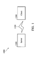
- Fig. 1 is a schematic diagram illustrating an embodiment of a device management system of the invention
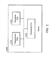
- Fig. 2 is a schematic diagram illustrating an embodiment of a server of the invention
- Fig. 3 is a schematic diagram illustrating an embodiment of a client of the invention.
- Fig. 4 is a flowchart of an embodiment of a device management method of the invention.
- Fig. 5 is a flowchart of another embodiment of a device management method of the invention.
- Fig. 6 is a flowchart of another embodiment of a device management method of the invention.
- Fig. 7 is a flowchart of another embodiment of a device management method of the invention.
- Fig. 1 is a schematic diagram illustrating an embodiment of a device management system of the invention.
- the device management system 1000 comprises a server 1200 and at least one client 1300.
- the server 1200 and the client 1300 comprising a device management (DM) tree can couple with each other via a transmission medium 1100, such as wired or wireless communication. It is understood that, when the transmission medium 1100 is a wireless communication, any of the methods available such as a WAP Push or SMS can be used for transmission between the server 1200 and the client 1300.
- the server 1200 can perform related device management processes for the client 1300.
- Fig. 2 is a schematic diagram illustrating an embodiment of a server of the invention.
- the server 1200 may be an electronic device.
- the server 1200 comprises a transmission unit 1210, a reception unit 1220, and a processing unit 1230.
- the transmission unit 1210 or the reception unit 1220 may be a wired or wireless network adapter.
- the transmission unit 1210 and the reception unit 1220 can be integrated as a transceiver unit.
- the processing unit 1230 can transmit a command without any condition or with a specific condition to the client 1300 via the transmission unit 1210, receive a status message returned from the client 1300 via the reception unit 1220, and perform related analysis according to the received status message.
- the command may be various according to different applications.
- the command may have no condition, and the command will request the client 1300 to perform an operation to the DM tree.
- the command may have a specific condition, and the command will request the client 1300 to perform an operation to the DM tree using the specific condition.
- the command requests the client 1300 to add a MO to the DM tree, wherein the server 1200 can use the "./Inbox" in the URI of the command target. It is also understood that, in some embodiments, the command may also requests the client 1300 to add a MO to the DM tree in a path specified in the specific condition.
- the command could request the client 1300 to add a node to the DM tree, and name the node using a suggested name specified in the specific condition, wherein the server 1200 can put the suggested node name in the URI of the command target. It is understood that, the above embodiments are only examples of the present application, and the present invention is not limited thereto.
- Fig. 3 is a schematic diagram illustrating an embodiment of a client of the invention.
- the client 1300 may be an electronic device, such as a computer and a mobile device, comprising a PDA, a smart phone, a mobile phone, an MID, or a Netbook.
- the client 1300 comprises a transmission unit 1310, a reception unit 1320, a storage unit 1330, and a processing unit 1340.
- the transmission unit 1310 or the reception unit 1320 may be a wired or wireless network adapter, and the transmission unit 1310 and the reception unit 1320 can be integrated as a transceiver unit.
- the storage unit 1330 can comprise a DM tree 1331 conforming to the OMA DM protocol.
- the processing unit 1340 can receive a command via the reception unit 1320, and execute the command. Similarly, the command may have no condition, or have a specific condition, and the command may request the client 1300 to perform an operation to the DM tree 1331 with or without using the specific condition. The processing unit 1340 can generate and return a status message based on the execution of the command, which will be discussed further in the following paragraphs.
- Fig. 4 is a flowchart of an embodiment of a device management method of the invention.
- the device management method can be used for a server and a client, such as an electronic device, such as a computer or a mobile device comprising a PDA, a smart phone, a mobile phone, an MID, or a Netbook.
- step S4100 the server 1200 transmits a command to the client 1300.
- the command may have a specific condition.
- step S4200 the client 1300 receives the command from the server 1200, and in step S4300, the client 1300 executes the command optionally based on the specific condition.
- step S4400 it is determined whether the command executed in step S4300 is based on the specific condition.
- the client 1300 When the execution is based on the specific condition (Yes in step S4400), in step S4500, the client 1300 generates and returns a second status message to the server 1200.
- step S4600 the client 1300 generates and returns a first status message to the server 1200.
- step S4700 the server 1200 receives the first status message or the second status message from the client 1300. It is noted that, when the server 1200 recognizes the difference of the first status message from the second status message, the server 1200 can accordingly perform subsequent operations.
- the specific condition may comprise a path, wherein a MO is requested to be added to the DM tree in the path.
- the second status message is generated and returned to the server 1200.
- the first status message is generated and returned to the server 1200.
- the specific condition may comprise a suggested name.
- a node is requested to be added to the DM tree and named as the suggested name.
- the second status message is generated and returned to the server 1200.
- the first status message is generated and returned to the server 1200.
- the first status message and the second status message may have different status codes.
- the server 1200 recognizes the received status code (first status code) is different from the second status code, the server 1200 will know that the command executed in step S4300 is not based on the specific condition. That is to say, the actual path of the added MO or the actual node name of the added node is different from the path or the name specified in the specific condition, and the server 1200 can further determine whether to transmit another command, such as a 'Get' command to the client 1300, wherein the command requests the client 1300 to feed back the actual path of the MO in the DM tree or the actual node name of the node.
- another command such as a 'Get' command
- Fig. 5 is a flowchart of another embodiment of a device management method of the invention. Except step S5500, S5600 and S5700, the remaining steps are consistent with those in the embodiment of Fig.4 .
- step S5500 When the command is executed based on the specific condition (Yes in step S5400), in step S5500, the client 1300 generates and returns a status message to the server 1200.
- step S5600 the client 1300 generates and returns a status message comprising an actual execution state to the server 1200.
- step S5700 the server 1200 receives the status message generated in step S5500 or S5600 from the client 1300.
- the status message generated in step S5500 may comprise a second status code or an actual execution state wherein the actual execution state is consistent with the specific condition.
- the server 1200 since the status message comprises the actual execution state, the server 1200 will directly know the actual path of the added MO or the actual node name of the added node. Consequently, the server 1200 doesn't need to transmit another command, such as a 'Get' command.
- the specific condition may comprise a path, wherein a MO is requested to be added to the DM tree in the path.
- the status message is generated and returned to the server 1200 wherein the status message comprises a second status code, '200', or the requested path for the MO.
- the status message is generated and returned to the server 1200 wherein the status message comprises the actual path for the MO.
- the specific condition may comprise a suggested name.
- a node is requested to be added to the DM tree and named as the suggested name.
- the status message is generated and returned to the server 1200 wherein the status message comprises a second status code, '200', or the suggested node name.
- the status message is generated and returned to the server 1200 wherein the status message comprises the actual node name created for the node.
- the status message may have several data fields.
- a 'TargetRef' field can be used to record the actual execution state.
- Fig. 6 is a flowchart of another embodiment of a device management method of the invention. Except step S6500, S6600 and S6700, the remaining steps are consistent with those in the embodiment of Fig.4 .
- step S6500 When the command is executed based on the specific condition (Yes in step S6400), in step S6500, the client 1300 generates and returns a status message to the server 1200.
- step S6600 the client 1300 generates and returns a status message comprising a first status code and an actual execution state to the server 1200.
- step S6700 the server 1200 receives the status message generated in step S6500 or S6600 from the client 1300.
- the status message generated in step S6500 may comprise a second status code, an actual execution state or both wherein the actual execution state is consistent with the specific condition.
- the second status code in step S6500 is different from the first status code in step S6600.
- the server 1200 received in S6700 comprises a status code (the first or second status code) and an actual execution state
- the server 1200 can check the status code first and determine whether to check the actual execution state based on the check of the status code.
- the specific condition may comprise a path, wherein a MO is requested to be added to the DM tree in the path.
- the status message is generated and returned to the server 1200 wherein the status message comprises a second status code, '200', and the requested path for the MO.
- the status message is generated and returned to the server 1200 wherein the status message comprises the first status code,'220', and the actual path for the MO.
- the specific condition may comprise a suggested name.
- a node is requested to be added to the DM tree and named as the suggested name.
- the status message is generated and returned to the server 1200 wherein the status message comprises a second status code, '200', and the suggested node name.
- the status message is generated and returned to the server 1200 wherein the status message comprises the first status code,'220', and the actual node name created for the node.
- the status message may have several data fields.
- a 'TargetRef field can be used to record the actual execution state.
- Fig. 7 is a flowchart of another embodiment of a device management method of the invention.
- the device management method can be used for a server and a client.
- step S7100 the server 1200 transmits a command to the client 1300.
- step S7200 the client 1300 receives the command from the server 1200, and in step S7300, the client 1300 executes the command.
- step S7400 the client 1300 generates and returns a status message to the server 1200.
- step S7500 the server 1200 receives the status message from the client 1300.
- the status message comprises a second status code and an actual execution state indicating the executing result.
- the status message comprises a first status code different from the second status code.
- the client 1300 will try to add a MO to the DM tree.
- the status message comprises a second status code, e.g. "200”, and the actual MO path. Consequently, the server 1200 can get the executing result directly.
- the client 1300 fails to add a MO, the status message comprises a first status code, e.g. "220", different from the second status code.
- the client 1300 will try to add a node to the DM tree and name it.
- the status message comprises a second status code, e.g. "200”, and the actual node name. Consequently, the server 1200 can get the executing result directly.
- the client 1300 fails to add and name a node, the status message comprises a first status code, e.g. "220", different from the second status code.
- the device management methods and systems of the invention can enhance the applicability of status messages returned in response to commands for device management; thus, reducing unnecessary communications and saving system resources, and avoiding additional communication charges.
- Device management methods may take the form of a program code (i.e., executable instructions) embodied in tangible media, such as floppy diskettes, CD-ROMS, hard drives, or any other machine-readable storage medium, wherein, when the program code is loaded into and executed by a machine, such as a computer, the machine thereby becomes an apparatus for practicing the methods.
- the methods may also be embodied in the form of a program code transmitted over some transmission medium, such as electrical wiring or cabling, through fiber optics, or via any other form of transmission, wherein, when the program code is received and loaded into and executed by a machine, such as a computer, the machine becomes an apparatus for practicing the disclosed methods.
- the program code When implemented on a general-purpose processor, the program code combines with the processor to provide a unique apparatus that operates analogously to application specific logic circuits.
Landscapes
- Engineering & Computer Science (AREA)
- Computer Networks & Wireless Communication (AREA)
- Signal Processing (AREA)
- Computer Hardware Design (AREA)
- Theoretical Computer Science (AREA)
- Software Systems (AREA)
- Physics & Mathematics (AREA)
- General Engineering & Computer Science (AREA)
- General Physics & Mathematics (AREA)
- Computer And Data Communications (AREA)
- Telephonic Communication Services (AREA)
- Selective Calling Equipment (AREA)
Abstract
Description
- This application claims the benefit of
U.S. Provisional Application No. 61/316,610 filed March 23, 2010 - The disclosure relates generally to device management methods and systems, and, more particularly to device management methods and systems that enhance the applicability of status messages returned in response to commands for device management.
- Recently, portable devices, such as handheld devices, have become more and more technically advanced and multifunctional. For example, a handheld device may have telecommunication capabilities, e-mail message capabilities, an advanced address book management system, a media playback system, and various other functions. Due to increased convenience and functions of the devices, these devices have become basic necessities of life.
- The Open Mobile Alliance (OMA) is a standardization body which develops open standards for the mobile phone industry. The mission of the OMA is to provide interoperable service enablers to work in different countries. The OMA Device Management (DM) protocol is a device management protocol specified by the OMA DM working group and the data synchronization (DS) working group. The OMA DM was created to support device configuration, software upgrade, and fault management functions, among others. The communication protocol in the OMA DM is a request-response protocol between a server and a client. Generally, the communication is initiated by the server, asynchronously, using any of the communication methods available such as a WAP (Wireless Application Protocol) Push or SMS (Short Message Service). Once communications is established between the server and client, a sequence of messages can be exchanged to complete a given device management task.
- In the OMA DM protocol, each client has a DM tree, and supports an Inbox mechanism. In the Inbox mechanism, a server can transmit a command to the client, such as requesting the client to add a management object (MO) in the DM tree. The server can use the "./Inbox" in the URI (Uniform Resource Identifiers) of the command target, and the client can decide where to put the MO in the DM tree at will. Based on the OMA DM protocol, a client can respond to the command with a status message with a status code 200 when a command is successfully executed. After the server receives the status message, the server can know that the MO has been added to the DM tree, but doesn't know the exact path for the MO created in the client. Since the server doesn't know the exact path for the MO, the server can use a "Get" command to get the specific sub-tree of the DM tree of the client. The additional "Get" command wastes communications and system resources, such as power, and causes users to be charged more for communications fees.
- Device management methods and systems are provided.
- In an embodiment of a device management method, a command is received. The command is executed. When the command is not executed successfully, a status message comprising a first status code is generated. When the command is executed successfully, the status message comprising a second status code and an actual execution state is generated. The first status code is different from the second status code.
- An embodiment of a client comprises a storage unit, a reception unit, and a processing unit. The storage unit comprises a device management tree. The reception unit receives a command. The processing unit executes the command and generates a status message. When the processing unit fails to execute the command, the status message comprises a first status code. When the processing unit executes the command successfully, the status message comprises an actual execution state and a second status code different from the first status code.
- An embodiment of a client comprises a storage unit, a reception unit, and a processing unit. The storage unit comprises a device management tree. The reception unit receives a command comprising a specific condition. The processing unit executes the command optionally based on the specific condition. When the execution is not based on the specific condition, the processing unit generates a status message comprising an actual execution state.
- An embodiment of a client comprises a storage unit, a reception unit, and a processing unit. The storage unit comprises a device management tree. The reception unit receives a command comprising a specific path. The processing unit adds a management object to the device management tree. When the processing unit adds the management object in an actual path different from the specific path, the processing unit generates a first status code. When the processing unit adds the management object in the specific path, the processing unit generates a second status code different from the first status code.
- An embodiment of a client comprises a storage unit, a reception unit, and a processing unit. The storage unit comprises a device management tree. The reception unit receives a command comprising a suggested name. The processing unit adds a node to the device management tree and names the node. When the processing unit names the node using an actual node name different from the suggested name, the processing unit generates a first status code. When the processing unit names the node using the suggested name, the processing unit generates a second status code different from the first status code.
- An embodiment of a device management system comprises a server and a client. The server transmits a command. The client executes the command and transmits a status message comprising a status code and an actual execution state to the server. The server checks the status code of the status message, and determines whether to check the actual execution state based on the check of the status code.
- Device management methods may take the form of a program code embodied in a tangible media. When the program code is loaded into and executed by a machine, the machine becomes an apparatus for practicing the disclosed method.
- The invention will become more fully understood by referring to the following detailed description with reference to the accompanying drawings, wherein:
-
Fig. 1 is a schematic diagram illustrating an embodiment of a device management system of the invention; -
Fig. 2 is a schematic diagram illustrating an embodiment of a server of the invention; -
Fig. 3 is a schematic diagram illustrating an embodiment of a client of the invention; -
Fig. 4 is a flowchart of an embodiment of a device management method of the invention; -
Fig. 5 is a flowchart of another embodiment of a device management method of the invention; -
Fig. 6 is a flowchart of another embodiment of a device management method of the invention; and -
Fig. 7 is a flowchart of another embodiment of a device management method of the invention. - Device management methods and systems are provided.
-
Fig. 1 is a schematic diagram illustrating an embodiment of a device management system of the invention. - The
device management system 1000 comprises aserver 1200 and at least oneclient 1300. Theserver 1200 and theclient 1300 comprising a device management (DM) tree can couple with each other via atransmission medium 1100, such as wired or wireless communication. It is understood that, when thetransmission medium 1100 is a wireless communication, any of the methods available such as a WAP Push or SMS can be used for transmission between theserver 1200 and theclient 1300. Theserver 1200 can perform related device management processes for theclient 1300. -
Fig. 2 is a schematic diagram illustrating an embodiment of a server of the invention. Theserver 1200 may be an electronic device. Theserver 1200 comprises atransmission unit 1210, areception unit 1220, and aprocessing unit 1230. In some embodiments, thetransmission unit 1210 or thereception unit 1220 may be a wired or wireless network adapter. In some embodiments, thetransmission unit 1210 and thereception unit 1220 can be integrated as a transceiver unit. Theprocessing unit 1230 can transmit a command without any condition or with a specific condition to theclient 1300 via thetransmission unit 1210, receive a status message returned from theclient 1300 via thereception unit 1220, and perform related analysis according to the received status message. - It is noted that, the command may be various according to different applications. In some embodiments, the command may have no condition, and the command will request the
client 1300 to perform an operation to the DM tree. In some embodiments, the command may have a specific condition, and the command will request theclient 1300 to perform an operation to the DM tree using the specific condition. In the Inbox mechanism, the command requests theclient 1300 to add a MO to the DM tree, wherein theserver 1200 can use the "./Inbox" in the URI of the command target. It is also understood that, in some embodiments, the command may also requests theclient 1300 to add a MO to the DM tree in a path specified in the specific condition. Further, the command could request theclient 1300 to add a node to the DM tree, and name the node using a suggested name specified in the specific condition, wherein theserver 1200 can put the suggested node name in the URI of the command target. It is understood that, the above embodiments are only examples of the present application, and the present invention is not limited thereto. -
Fig. 3 is a schematic diagram illustrating an embodiment of a client of the invention. Theclient 1300 may be an electronic device, such as a computer and a mobile device, comprising a PDA, a smart phone, a mobile phone, an MID, or a Netbook. Theclient 1300 comprises atransmission unit 1310, areception unit 1320, astorage unit 1330, and aprocessing unit 1340. Similarly, in some embodiments, thetransmission unit 1310 or thereception unit 1320 may be a wired or wireless network adapter, and thetransmission unit 1310 and thereception unit 1320 can be integrated as a transceiver unit. Thestorage unit 1330 can comprise aDM tree 1331 conforming to the OMA DM protocol. It is understood that, the OMA DM protocol, DM tree, and related terminologies are well known in the art, and omitted here. Theprocessing unit 1340 can receive a command via thereception unit 1320, and execute the command. Similarly, the command may have no condition, or have a specific condition, and the command may request theclient 1300 to perform an operation to theDM tree 1331 with or without using the specific condition. Theprocessing unit 1340 can generate and return a status message based on the execution of the command, which will be discussed further in the following paragraphs. -
Fig. 4 is a flowchart of an embodiment of a device management method of the invention. The device management method can be used for a server and a client, such as an electronic device, such as a computer or a mobile device comprising a PDA, a smart phone, a mobile phone, an MID, or a Netbook. - In step S4100, the
server 1200 transmits a command to theclient 1300. It is noted that, the command may have a specific condition. In step S4200, theclient 1300 receives the command from theserver 1200, and in step S4300, theclient 1300 executes the command optionally based on the specific condition. In step S4400, it is determined whether the command executed in step S4300 is based on the specific condition. When the execution is based on the specific condition (Yes in step S4400), in step S4500, theclient 1300 generates and returns a second status message to theserver 1200. When the execution is not based on the specific condition (No in step S4400), in step S4600, theclient 1300 generates and returns a first status message to theserver 1200. In step S4700, theserver 1200 receives the first status message or the second status message from theclient 1300. It is noted that, when theserver 1200 recognizes the difference of the first status message from the second status message, theserver 1200 can accordingly perform subsequent operations. - For example, in the Inbox mechanism, the specific condition may comprise a path, wherein a MO is requested to be added to the DM tree in the path. When a MO is added to the DM tree in the path specified in the specific condition, the second status message is generated and returned to the
server 1200. On the other hand, when a MO is added to the DM tree, but the MO is not added in the path specified in the specific condition, the first status message is generated and returned to theserver 1200. - Besides, the specific condition may comprise a suggested name. A node is requested to be added to the DM tree and named as the suggested name. When a node with a suggested name specified in the specific condition is added to the DM tree, the second status message is generated and returned to the
server 1200. On the other hand, when a node is added to the DM tree, but the node is not named using the suggested name, the first status message is generated and returned to theserver 1200. - It is noted that, in some embodiments, the first status message and the second status message may have different status codes. When the
server 1200 recognizes the received status code (first status code) is different from the second status code, theserver 1200 will know that the command executed in step S4300 is not based on the specific condition. That is to say, the actual path of the added MO or the actual node name of the added node is different from the path or the name specified in the specific condition, and theserver 1200 can further determine whether to transmit another command, such as a 'Get' command to theclient 1300, wherein the command requests theclient 1300 to feed back the actual path of the MO in the DM tree or the actual node name of the node. -
Fig. 5 is a flowchart of another embodiment of a device management method of the invention. Except step S5500, S5600 and S5700, the remaining steps are consistent with those in the embodiment ofFig.4 . - When the command is executed based on the specific condition (Yes in step S5400), in step S5500, the
client 1300 generates and returns a status message to theserver 1200. When the command is not executed based on the specific condition (No in step S5400), in step S5600, theclient 1300 generates and returns a status message comprising an actual execution state to theserver 1200. In step S5700, theserver 1200 receives the status message generated in step S5500 or S5600 from theclient 1300. - Please note that the status message generated in step S5500 may comprise a second status code or an actual execution state wherein the actual execution state is consistent with the specific condition. In addition, since the status message comprises the actual execution state, the
server 1200 will directly know the actual path of the added MO or the actual node name of the added node. Consequently, theserver 1200 doesn't need to transmit another command, such as a 'Get' command. - For example, in the Inbox mechanism, the specific condition may comprise a path, wherein a MO is requested to be added to the DM tree in the path. When a MO is added to the DM tree in the path specified in the specific condition, the status message is generated and returned to the
server 1200 wherein the status message comprises a second status code, '200', or the requested path for the MO. On the other hand, when a MO is added to the DM tree, but the MO is not added in the path specified in the specific condition, the status message is generated and returned to theserver 1200 wherein the status message comprises the actual path for the MO. - Besides, the specific condition may comprise a suggested name. A node is requested to be added to the DM tree and named as the suggested name. When a node with a suggested name specified in the specific condition is added to the DM tree, the status message is generated and returned to the
server 1200 wherein the status message comprises a second status code, '200', or the suggested node name. On the other hand, when a node is added to the DM tree, but the node is not named using the suggested name, the status message is generated and returned to theserver 1200 wherein the status message comprises the actual node name created for the node. - It is noted that, the status message may have several data fields. In some embodiments, a 'TargetRef' field can be used to record the actual execution state.
-
Fig. 6 is a flowchart of another embodiment of a device management method of the invention. Except step S6500, S6600 and S6700, the remaining steps are consistent with those in the embodiment ofFig.4 . - When the command is executed based on the specific condition (Yes in step S6400), in step S6500, the
client 1300 generates and returns a status message to theserver 1200. When the command is not executed based on the specific condition (No in step S6400), in step S6600, theclient 1300 generates and returns a status message comprising a first status code and an actual execution state to theserver 1200. In step S6700, theserver 1200 receives the status message generated in step S6500 or S6600 from theclient 1300. - Please note that the status message generated in step S6500 may comprise a second status code, an actual execution state or both wherein the actual execution state is consistent with the specific condition. In addition, the second status code in step S6500 is different from the first status code in step S6600.
- In case the status message the
server 1200 received in S6700 comprises a status code (the first or second status code) and an actual execution state, theserver 1200 can check the status code first and determine whether to check the actual execution state based on the check of the status code. - For example, in the Inbox mechanism, the specific condition may comprise a path, wherein a MO is requested to be added to the DM tree in the path. When a MO is added to the DM tree in the path specified in the specific condition, the status message is generated and returned to the
server 1200 wherein the status message comprises a second status code, '200', and the requested path for the MO. On the other hand, when a MO is added to the DM tree, but the MO is not added in the path specified in the specific condition, the status message is generated and returned to theserver 1200 wherein the status message comprises the first status code,'220', and the actual path for the MO. - Besides, the specific condition may comprise a suggested name. A node is requested to be added to the DM tree and named as the suggested name. When a node with a suggested name specified in the specific condition is added to the DM tree, the status message is generated and returned to the
server 1200 wherein the status message comprises a second status code, '200', and the suggested node name. On the other hand, when a node is added to the DM tree, but the node is not named using the suggested name, the status message is generated and returned to theserver 1200 wherein the status message comprises the first status code,'220', and the actual node name created for the node. - It is noted that, the status message may have several data fields. In some embodiments, a 'TargetRef field can be used to record the actual execution state.
-
Fig. 7 is a flowchart of another embodiment of a device management method of the invention. The device management method can be used for a server and a client. - In step S7100, the
server 1200 transmits a command to theclient 1300. In step S7200, theclient 1300 receives the command from theserver 1200, and in step S7300, theclient 1300 executes the command. In step S7400, theclient 1300 generates and returns a status message to theserver 1200. In step S7500, theserver 1200 receives the status message from theclient 1300. - It is noted that in case the
client 1300 executes the command successfully, the status message comprises a second status code and an actual execution state indicating the executing result. On the other hand, in case theclient 1300 fails to execute the command, the status message comprises a first status code different from the second status code. - For example, in the Inbox mechanism, the
client 1300 will try to add a MO to the DM tree. When a MO is added to the DM tree successfully, the status message comprises a second status code, e.g. "200", and the actual MO path. Consequently, theserver 1200 can get the executing result directly. On the other hand, when theclient 1300 fails to add a MO, the status message comprises a first status code, e.g. "220", different from the second status code. - Besides, the
client 1300 will try to add a node to the DM tree and name it. When a node is added and named successfully, the status message comprises a second status code, e.g. "200", and the actual node name. Consequently, theserver 1200 can get the executing result directly. On the other hand, when theclient 1300 fails to add and name a node, the status message comprises a first status code, e.g. "220", different from the second status code. - Therefore, the device management methods and systems of the invention can enhance the applicability of status messages returned in response to commands for device management; thus, reducing unnecessary communications and saving system resources, and avoiding additional communication charges.
- Device management methods, or certain aspects or portions thereof, may take the form of a program code (i.e., executable instructions) embodied in tangible media, such as floppy diskettes, CD-ROMS, hard drives, or any other machine-readable storage medium, wherein, when the program code is loaded into and executed by a machine, such as a computer, the machine thereby becomes an apparatus for practicing the methods. The methods may also be embodied in the form of a program code transmitted over some transmission medium, such as electrical wiring or cabling, through fiber optics, or via any other form of transmission, wherein, when the program code is received and loaded into and executed by a machine, such as a computer, the machine becomes an apparatus for practicing the disclosed methods. When implemented on a general-purpose processor, the program code combines with the processor to provide a unique apparatus that operates analogously to application specific logic circuits.
- While the invention has been described by way of example and in terms of preferred embodiment, it is to be understood that the invention is not limited thereto. Those who are skilled in this technology can still make various alterations and modifications without departing from the scope and spirit of this invention. Therefore, the scope of the present invention shall be defined and protected by the following claims and their equivalents.
Claims (15)
- A device management method for use in an electronic device comprising a device management tree, comprising steps of:receiving a command;executing the command;generating a status message comprising a first status code when the command is not executed successfully; andgenerating the status message comprising a second status code and an actual execution state when the command is executed successfully;wherein the first status code is different from the second status code.
- The method of claim 1, wherein the step of executing the command includes adding a management object to the device management tree;
when the management object is successfully added to the device management tree, the status message comprises the second status code and an actual path for the management object. - The method of claim 1, wherein the step of executing the command includes adding a node to the device management tree and naming the node;
when the node is successfully added to the device management tree and named, the status message comprises the second status code and an actual node name for the node. - A client, comprising:a storage unit comprising a device management tree;a reception unit receiving a command; anda processing unit executing the command and generating a status message;wherein when the processing unit fails to execute the command, the status message comprises a first status code, and when the processing unit executes the command successfully, the status message comprises an actual execution state and a second status code different from the first status code.
- The client of claim 4, wherein when the processing unit successfully adds a management object to the device management tree based on the command, the status message comprises the second status code and an actual path for the management object.
- The client of claim 4, wherein when the processing unit successfully adds a node to the device management tree and names the node based on the command, the status message comprises the second status code and an actual node name for the node.
- A client, comprising:a storage unit comprising a device management tree;a reception unit receiving a command comprising a specific condition; anda processing unit executing the command optionally based on the specific condition, and when the execution is not based on the specific condition, generating a status message comprising an actual execution state.
- The client of claim 7, wherein the specific condition comprises a specific path in the device management tree, and the command received by the reception unit requests the processing unit to add a management object to the device management tree in the specific path;
when the processing unit adds the management object in an actual path different from the specific path, the status message generated by the processing unit comprises the actual path for the management object. - The client of claim 8, wherein when the processing unit adds the management object in the specific path, the status message generated by the processing unit comprises the actual path for the management object.
- The client of claim 8, wherein when the processing unit adds the management object in the specific path, the status message generated by the processing unit comprises a second status code;
when the processing unit adds the management object in the actual path different from the specific path, the status message generated by the processing unit further comprises a first status code, wherein the first status code and the second status code are different. - The client of claim 7, wherein the specific condition comprises a suggested name, and the command received by the reception unit requests the processing unit to add a node to the device management tree and name the node;
when the processing unit adds the node to the device management tree and names the node using an actual node name different from the suggestion name, the status message generated by the processing unit comprises the actual node name. - The client of claim 11, wherein when the processing unit names the node using the suggested name, the status message generated by the processing unit comprises the actual node name.
- The client of claim 11, wherein when the processing unit names the node using the suggested name, the status message generated by the processing unit comprises a second status code;
when the processing unit names the node using the actual node name different from the suggestion name, the status message generated by the processing unit further comprises a first status code, wherein the first status code and the second status code are different. - A client, comprising:a storage unit comprising a device management tree;a reception unit receiving a command comprising a specific path; anda processing unit adding a management object to the device management tree;wherein when the processing unit adds the management object in an actual path different from the specific path, the processing unit generates a first status code, and when the processing unit adds the management object in the specific path, the processing unit generates a second status code different from the first status code.
- A client, comprising:a storage unit comprising a device management tree;a reception unit receiving a command comprising a suggested name; anda processing unit adding a node to the device management tree and naming the node;wherein when the processing unit names the node using an actual node name different from the suggested name, the processing unit generates a first status code, and when the processing unit names the node using the suggested name, the processing unit generates a second status code different from the first status code.
Priority Applications (1)
| Application Number | Priority Date | Filing Date | Title |
|---|---|---|---|
| EP13020028.0A EP2637358A1 (en) | 2010-03-23 | 2011-03-22 | Device management using a device management tree |
Applications Claiming Priority (2)
| Application Number | Priority Date | Filing Date | Title |
|---|---|---|---|
| US31661010P | 2010-03-23 | 2010-03-23 | |
| US13/010,200 US9026582B2 (en) | 2010-03-23 | 2011-01-20 | Device management methods and related apparatus for enhancing applicability of status messages in response to commands |
Publications (3)
| Publication Number | Publication Date |
|---|---|
| EP2369786A2 true EP2369786A2 (en) | 2011-09-28 |
| EP2369786A3 EP2369786A3 (en) | 2011-10-26 |
| EP2369786B1 EP2369786B1 (en) | 2013-06-05 |
Family
ID=44168915
Family Applications (2)
| Application Number | Title | Priority Date | Filing Date |
|---|---|---|---|
| EP13020028.0A Withdrawn EP2637358A1 (en) | 2010-03-23 | 2011-03-22 | Device management using a device management tree |
| EP11002366.0A Active EP2369786B1 (en) | 2010-03-23 | 2011-03-22 | Device management client and method using a device management tree |
Family Applications Before (1)
| Application Number | Title | Priority Date | Filing Date |
|---|---|---|---|
| EP13020028.0A Withdrawn EP2637358A1 (en) | 2010-03-23 | 2011-03-22 | Device management using a device management tree |
Country Status (6)
| Country | Link |
|---|---|
| US (1) | US9026582B2 (en) |
| EP (2) | EP2637358A1 (en) |
| JP (1) | JP5462207B2 (en) |
| KR (1) | KR101269715B1 (en) |
| CN (1) | CN102201931B (en) |
| TW (1) | TWI462015B (en) |
Families Citing this family (6)
| Publication number | Priority date | Publication date | Assignee | Title |
|---|---|---|---|---|
| CN102685728B (en) * | 2011-03-14 | 2014-10-08 | 鸿富锦精密工业(深圳)有限公司 | WiMAX (Worldwide Interoperability for Microwave Access) client and parameter setting method thereof |
| CN102394780B (en) * | 2011-11-08 | 2014-09-03 | 迈普通信技术股份有限公司 | Equipment management system and method |
| US9515204B2 (en) | 2012-08-07 | 2016-12-06 | Rambus Inc. | Synchronous wired-or ACK status for memory with variable write latency |
| CN104601588A (en) * | 2015-01-29 | 2015-05-06 | 成都三零瑞通移动通信有限公司 | Safety management method based on circuit domain |
| US10152498B2 (en) * | 2015-12-11 | 2018-12-11 | Emc Corporation | Providing storage technology information to improve database performance |
| US10216433B2 (en) | 2015-12-11 | 2019-02-26 | EMC IP Holding Company LLC | Accessing a virtual volume on a storage array |
Citations (1)
| Publication number | Priority date | Publication date | Assignee | Title |
|---|---|---|---|---|
| US20090271781A1 (en) | 2007-06-11 | 2009-10-29 | Cui Shouling | Method, system, terminal and device management server for installing software components |
Family Cites Families (24)
| Publication number | Priority date | Publication date | Assignee | Title |
|---|---|---|---|---|
| US6721871B2 (en) * | 2002-04-02 | 2004-04-13 | Nokia Corporation | Method and apparatus for synchronizing data stores with respect to changes in folders |
| FI120613B (en) | 2004-01-30 | 2009-12-15 | Nokia Corp | Determination of nodes in a device management system |
| US20060031449A1 (en) * | 2004-07-01 | 2006-02-09 | Mika Hallamaa | Selection of management method |
| CN101442529B (en) | 2004-07-09 | 2013-05-01 | Lg电子株式会社 | Device management system and device management command scheduling method thereof |
| EP1766866B1 (en) | 2004-07-09 | 2018-10-03 | LG Electronics Inc. | Network device management command scheduling |
| KR100641238B1 (en) * | 2004-07-09 | 2006-11-02 | 엘지전자 주식회사 | Device management system and device management command scheduling method thereof |
| US7865483B2 (en) * | 2005-09-21 | 2011-01-04 | Lg Electronics Inc. | Device management system and method for managing device management object |
| KR100747466B1 (en) * | 2005-10-01 | 2007-08-09 | 엘지전자 주식회사 | Device management method and device management client using node with additional attributes |
| CN100361456C (en) * | 2005-10-13 | 2008-01-09 | 华为技术有限公司 | Terminal device management method and terminal device thereof |
| US20070106770A1 (en) * | 2005-11-10 | 2007-05-10 | Svante Alnas | Managing a remote device by a communication element that does not specify an identifier for the management object |
| JP2007172244A (en) | 2005-12-21 | 2007-07-05 | Sharp Corp | Content management system, content recording / playback apparatus, related information acquisition program, and related information acquisition apparatus |
| KR101285886B1 (en) | 2006-01-25 | 2013-07-11 | 엘지전자 주식회사 | Method for reporting to server and terminal thereof |
| WO2007089123A1 (en) * | 2006-02-03 | 2007-08-09 | Lg Electronics Inc. | Method, system and terminal for changing a management object of broadcast service guide |
| CN101083608A (en) * | 2006-05-30 | 2007-12-05 | 华为技术有限公司 | Method for enquiring node information of equipment management tree and its terminal equipment |
| CN101123785B (en) * | 2006-08-11 | 2013-01-23 | 华为技术有限公司 | A method and system for management terminals in communication system |
| KR101281931B1 (en) * | 2007-04-06 | 2013-08-26 | 삼성전자주식회사 | System and method for device management security of trap management object |
| EP2188696A4 (en) * | 2007-08-08 | 2014-09-17 | Innopath Software Inc | WORKFLOW-BASED USER INTERFACE SYSTEM FOR MANAGING MOBILE DEVICES |
| CN101409632B (en) * | 2007-10-10 | 2011-02-02 | 华为技术有限公司 | Transmission method, system and apparatus for remote procedure call command |
| CN101505550B (en) * | 2008-02-04 | 2012-08-22 | 华为技术有限公司 | Device management method, terminal, device and system |
| US8019899B2 (en) * | 2008-08-28 | 2011-09-13 | Yahoo! Inc. | Delivering partially processed results based on system metrics in network content delivery systems |
| KR101506040B1 (en) * | 2009-04-02 | 2015-03-25 | 삼성전자주식회사 | Apparatus and method for supporting multiple DM management rights |
| CN101877861B (en) * | 2009-04-30 | 2015-05-06 | 中兴通讯股份有限公司 | Node information acquisition method, client and server |
| US9467338B2 (en) * | 2010-04-01 | 2016-10-11 | Blackberry Limited | Method for communicating device management data changes |
| US8924544B2 (en) * | 2010-12-07 | 2014-12-30 | Samsung Electronics Co., Ltd. | Techniques for sessionless reporting by device management client |
-
2011
- 2011-01-20 US US13/010,200 patent/US9026582B2/en active Active
- 2011-02-25 KR KR1020110017331A patent/KR101269715B1/en not_active Expired - Fee Related
- 2011-03-03 JP JP2011046270A patent/JP5462207B2/en active Active
- 2011-03-15 TW TW100108676A patent/TWI462015B/en active
- 2011-03-22 EP EP13020028.0A patent/EP2637358A1/en not_active Withdrawn
- 2011-03-22 EP EP11002366.0A patent/EP2369786B1/en active Active
- 2011-03-23 CN CN201110070226.5A patent/CN102201931B/en active Active
Patent Citations (1)
| Publication number | Priority date | Publication date | Assignee | Title |
|---|---|---|---|---|
| US20090271781A1 (en) | 2007-06-11 | 2009-10-29 | Cui Shouling | Method, system, terminal and device management server for installing software components |
Also Published As
| Publication number | Publication date |
|---|---|
| KR20110106793A (en) | 2011-09-29 |
| CN102201931A (en) | 2011-09-28 |
| US20110238740A1 (en) | 2011-09-29 |
| CN102201931B (en) | 2014-05-28 |
| TW201140444A (en) | 2011-11-16 |
| TWI462015B (en) | 2014-11-21 |
| US9026582B2 (en) | 2015-05-05 |
| EP2369786B1 (en) | 2013-06-05 |
| KR101269715B1 (en) | 2013-07-04 |
| EP2369786A3 (en) | 2011-10-26 |
| JP5462207B2 (en) | 2014-04-02 |
| EP2637358A1 (en) | 2013-09-11 |
| JP2011198361A (en) | 2011-10-06 |
Similar Documents
| Publication | Publication Date | Title |
|---|---|---|
| EP2369786B1 (en) | Device management client and method using a device management tree | |
| US8774844B2 (en) | Integrated messaging | |
| US20140351711A1 (en) | Integrated Messaging | |
| CN104486388A (en) | Accessing method and device of cloud storage file | |
| KR101528210B1 (en) | Software downloading method and device | |
| US8855583B2 (en) | Communication system, communication terminal, server, communication method to be used therein and program therefor | |
| CN108712320B (en) | Message pushing method and device | |
| US20100184412A1 (en) | Method and system for internet communication by mobile phone | |
| EP2814201A1 (en) | Notification message sending method, system, manipulation apparatus, and terminal device | |
| KR100818962B1 (en) | Remote Management Methods for Mobile Devices | |
| CN102053917B (en) | Smart card capable of reducing memory footprint and instruction processing method thereof | |
| CN105187474A (en) | Information processing method and server | |
| CN103532941A (en) | Graphical page presentation method and device in CGS (client gateway server) mode | |
| CN113206872B (en) | Message sending method, terminal and computer storage medium | |
| EP2381620A1 (en) | Method for retrieving object from device management client and associated device management system | |
| CN105991736B (en) | A remote control method and device | |
| WO2007006859A1 (en) | Method and device arrangement for managing a client/server environment | |
| CN112688980B (en) | Resource distribution method and device, and computer equipment | |
| CN105763511A (en) | Business processing method and communication system | |
| US9373121B1 (en) | User communication device control with operating system action request messages | |
| JP5635053B2 (en) | Position information transmitting apparatus and method | |
| JP2010505309A (en) | Method for providing a centralized messaging service for at least one terminal and corresponding working unit of a mobile radio network system | |
| KR102870054B1 (en) | Server, methoed and computer program for providing non-face-to-face ordering service | |
| KR101973959B1 (en) | Apparatus and method for contorolling sesseion | |
| EP2421199A1 (en) | Method for transforming a workflow into a management object tree |
Legal Events
| Date | Code | Title | Description |
|---|---|---|---|
| PUAI | Public reference made under article 153(3) epc to a published international application that has entered the european phase |
Free format text: ORIGINAL CODE: 0009012 |
|
| PUAL | Search report despatched |
Free format text: ORIGINAL CODE: 0009013 |
|
| 17P | Request for examination filed |
Effective date: 20110322 |
|
| AK | Designated contracting states |
Kind code of ref document: A2 Designated state(s): AL AT BE BG CH CY CZ DE DK EE ES FI FR GB GR HR HU IE IS IT LI LT LU LV MC MK MT NL NO PL PT RO RS SE SI SK SM TR |
|
| AX | Request for extension of the european patent |
Extension state: BA ME |
|
| AK | Designated contracting states |
Kind code of ref document: A3 Designated state(s): AL AT BE BG CH CY CZ DE DK EE ES FI FR GB GR HR HU IE IS IT LI LT LU LV MC MK MT NL NO PL PT RO RS SE SI SK SM TR |
|
| AX | Request for extension of the european patent |
Extension state: BA ME |
|
| RIC1 | Information provided on ipc code assigned before grant |
Ipc: H04L 12/24 20060101AFI20110921BHEP Ipc: G06F 17/30 20060101ALI20110921BHEP Ipc: H04L 29/08 20060101ALI20110921BHEP |
|
| 17Q | First examination report despatched |
Effective date: 20120625 |
|
| GRAP | Despatch of communication of intention to grant a patent |
Free format text: ORIGINAL CODE: EPIDOSNIGR1 |
|
| RIN1 | Information on inventor provided before grant (corrected) |
Inventor name: YU, CHUN-TA |
|
| GRAS | Grant fee paid |
Free format text: ORIGINAL CODE: EPIDOSNIGR3 |
|
| GRAA | (expected) grant |
Free format text: ORIGINAL CODE: 0009210 |
|
| AK | Designated contracting states |
Kind code of ref document: B1 Designated state(s): AL AT BE BG CH CY CZ DE DK EE ES FI FR GB GR HR HU IE IS IT LI LT LU LV MC MK MT NL NO PL PT RO RS SE SI SK SM TR |
|
| REG | Reference to a national code |
Ref country code: GB Ref legal event code: FG4D |
|
| REG | Reference to a national code |
Ref country code: CH Ref legal event code: EP |
|
| REG | Reference to a national code |
Ref country code: AT Ref legal event code: REF Ref document number: 616203 Country of ref document: AT Kind code of ref document: T Effective date: 20130615 |
|
| REG | Reference to a national code |
Ref country code: IE Ref legal event code: FG4D |
|
| REG | Reference to a national code |
Ref country code: DE Ref legal event code: R096 Ref document number: 602011001853 Country of ref document: DE Effective date: 20130801 |
|
| REG | Reference to a national code |
Ref country code: NL Ref legal event code: T3 |
|
| REG | Reference to a national code |
Ref country code: AT Ref legal event code: MK05 Ref document number: 616203 Country of ref document: AT Kind code of ref document: T Effective date: 20130605 |
|
| PG25 | Lapsed in a contracting state [announced via postgrant information from national office to epo] |
Ref country code: LT Free format text: LAPSE BECAUSE OF FAILURE TO SUBMIT A TRANSLATION OF THE DESCRIPTION OR TO PAY THE FEE WITHIN THE PRESCRIBED TIME-LIMIT Effective date: 20130605 Ref country code: SI Free format text: LAPSE BECAUSE OF FAILURE TO SUBMIT A TRANSLATION OF THE DESCRIPTION OR TO PAY THE FEE WITHIN THE PRESCRIBED TIME-LIMIT Effective date: 20130605 Ref country code: GR Free format text: LAPSE BECAUSE OF FAILURE TO SUBMIT A TRANSLATION OF THE DESCRIPTION OR TO PAY THE FEE WITHIN THE PRESCRIBED TIME-LIMIT Effective date: 20130906 Ref country code: ES Free format text: LAPSE BECAUSE OF FAILURE TO SUBMIT A TRANSLATION OF THE DESCRIPTION OR TO PAY THE FEE WITHIN THE PRESCRIBED TIME-LIMIT Effective date: 20130916 Ref country code: NO Free format text: LAPSE BECAUSE OF FAILURE TO SUBMIT A TRANSLATION OF THE DESCRIPTION OR TO PAY THE FEE WITHIN THE PRESCRIBED TIME-LIMIT Effective date: 20130905 Ref country code: SE Free format text: LAPSE BECAUSE OF FAILURE TO SUBMIT A TRANSLATION OF THE DESCRIPTION OR TO PAY THE FEE WITHIN THE PRESCRIBED TIME-LIMIT Effective date: 20130605 Ref country code: FI Free format text: LAPSE BECAUSE OF FAILURE TO SUBMIT A TRANSLATION OF THE DESCRIPTION OR TO PAY THE FEE WITHIN THE PRESCRIBED TIME-LIMIT Effective date: 20130605 Ref country code: AT Free format text: LAPSE BECAUSE OF FAILURE TO SUBMIT A TRANSLATION OF THE DESCRIPTION OR TO PAY THE FEE WITHIN THE PRESCRIBED TIME-LIMIT Effective date: 20130605 |
|
| REG | Reference to a national code |
Ref country code: LT Ref legal event code: MG4D |
|
| PG25 | Lapsed in a contracting state [announced via postgrant information from national office to epo] |
Ref country code: RS Free format text: LAPSE BECAUSE OF FAILURE TO SUBMIT A TRANSLATION OF THE DESCRIPTION OR TO PAY THE FEE WITHIN THE PRESCRIBED TIME-LIMIT Effective date: 20130605 Ref country code: BG Free format text: LAPSE BECAUSE OF FAILURE TO SUBMIT A TRANSLATION OF THE DESCRIPTION OR TO PAY THE FEE WITHIN THE PRESCRIBED TIME-LIMIT Effective date: 20130905 Ref country code: HR Free format text: LAPSE BECAUSE OF FAILURE TO SUBMIT A TRANSLATION OF THE DESCRIPTION OR TO PAY THE FEE WITHIN THE PRESCRIBED TIME-LIMIT Effective date: 20130605 |
|
| PG25 | Lapsed in a contracting state [announced via postgrant information from national office to epo] |
Ref country code: LV Free format text: LAPSE BECAUSE OF FAILURE TO SUBMIT A TRANSLATION OF THE DESCRIPTION OR TO PAY THE FEE WITHIN THE PRESCRIBED TIME-LIMIT Effective date: 20130605 |
|
| PG25 | Lapsed in a contracting state [announced via postgrant information from national office to epo] |
Ref country code: BE Free format text: LAPSE BECAUSE OF FAILURE TO SUBMIT A TRANSLATION OF THE DESCRIPTION OR TO PAY THE FEE WITHIN THE PRESCRIBED TIME-LIMIT Effective date: 20130605 Ref country code: CZ Free format text: LAPSE BECAUSE OF FAILURE TO SUBMIT A TRANSLATION OF THE DESCRIPTION OR TO PAY THE FEE WITHIN THE PRESCRIBED TIME-LIMIT Effective date: 20130605 Ref country code: EE Free format text: LAPSE BECAUSE OF FAILURE TO SUBMIT A TRANSLATION OF THE DESCRIPTION OR TO PAY THE FEE WITHIN THE PRESCRIBED TIME-LIMIT Effective date: 20130605 Ref country code: PT Free format text: LAPSE BECAUSE OF FAILURE TO SUBMIT A TRANSLATION OF THE DESCRIPTION OR TO PAY THE FEE WITHIN THE PRESCRIBED TIME-LIMIT Effective date: 20131007 Ref country code: IS Free format text: LAPSE BECAUSE OF FAILURE TO SUBMIT A TRANSLATION OF THE DESCRIPTION OR TO PAY THE FEE WITHIN THE PRESCRIBED TIME-LIMIT Effective date: 20131005 Ref country code: SK Free format text: LAPSE BECAUSE OF FAILURE TO SUBMIT A TRANSLATION OF THE DESCRIPTION OR TO PAY THE FEE WITHIN THE PRESCRIBED TIME-LIMIT Effective date: 20130605 |
|
| PG25 | Lapsed in a contracting state [announced via postgrant information from national office to epo] |
Ref country code: PL Free format text: LAPSE BECAUSE OF FAILURE TO SUBMIT A TRANSLATION OF THE DESCRIPTION OR TO PAY THE FEE WITHIN THE PRESCRIBED TIME-LIMIT Effective date: 20130605 Ref country code: RO Free format text: LAPSE BECAUSE OF FAILURE TO SUBMIT A TRANSLATION OF THE DESCRIPTION OR TO PAY THE FEE WITHIN THE PRESCRIBED TIME-LIMIT Effective date: 20130605 |
|
| PLBE | No opposition filed within time limit |
Free format text: ORIGINAL CODE: 0009261 |
|
| STAA | Information on the status of an ep patent application or granted ep patent |
Free format text: STATUS: NO OPPOSITION FILED WITHIN TIME LIMIT |
|
| PG25 | Lapsed in a contracting state [announced via postgrant information from national office to epo] |
Ref country code: DK Free format text: LAPSE BECAUSE OF FAILURE TO SUBMIT A TRANSLATION OF THE DESCRIPTION OR TO PAY THE FEE WITHIN THE PRESCRIBED TIME-LIMIT Effective date: 20130605 |
|
| 26N | No opposition filed |
Effective date: 20140306 |
|
| PG25 | Lapsed in a contracting state [announced via postgrant information from national office to epo] |
Ref country code: IT Free format text: LAPSE BECAUSE OF FAILURE TO SUBMIT A TRANSLATION OF THE DESCRIPTION OR TO PAY THE FEE WITHIN THE PRESCRIBED TIME-LIMIT Effective date: 20130605 |
|
| REG | Reference to a national code |
Ref country code: DE Ref legal event code: R097 Ref document number: 602011001853 Country of ref document: DE Effective date: 20140306 |
|
| PG25 | Lapsed in a contracting state [announced via postgrant information from national office to epo] |
Ref country code: LU Free format text: LAPSE BECAUSE OF FAILURE TO SUBMIT A TRANSLATION OF THE DESCRIPTION OR TO PAY THE FEE WITHIN THE PRESCRIBED TIME-LIMIT Effective date: 20140322 |
|
| REG | Reference to a national code |
Ref country code: CH Ref legal event code: PL |
|
| REG | Reference to a national code |
Ref country code: IE Ref legal event code: MM4A |
|
| PG25 | Lapsed in a contracting state [announced via postgrant information from national office to epo] |
Ref country code: CH Free format text: LAPSE BECAUSE OF NON-PAYMENT OF DUE FEES Effective date: 20140331 Ref country code: IE Free format text: LAPSE BECAUSE OF NON-PAYMENT OF DUE FEES Effective date: 20140322 Ref country code: LI Free format text: LAPSE BECAUSE OF NON-PAYMENT OF DUE FEES Effective date: 20140331 |
|
| PG25 | Lapsed in a contracting state [announced via postgrant information from national office to epo] |
Ref country code: MT Free format text: LAPSE BECAUSE OF FAILURE TO SUBMIT A TRANSLATION OF THE DESCRIPTION OR TO PAY THE FEE WITHIN THE PRESCRIBED TIME-LIMIT Effective date: 20130605 |
|
| REG | Reference to a national code |
Ref country code: FR Ref legal event code: PLFP Year of fee payment: 6 |
|
| PG25 | Lapsed in a contracting state [announced via postgrant information from national office to epo] |
Ref country code: SM Free format text: LAPSE BECAUSE OF FAILURE TO SUBMIT A TRANSLATION OF THE DESCRIPTION OR TO PAY THE FEE WITHIN THE PRESCRIBED TIME-LIMIT Effective date: 20130605 |
|
| PG25 | Lapsed in a contracting state [announced via postgrant information from national office to epo] |
Ref country code: CY Free format text: LAPSE BECAUSE OF FAILURE TO SUBMIT A TRANSLATION OF THE DESCRIPTION OR TO PAY THE FEE WITHIN THE PRESCRIBED TIME-LIMIT Effective date: 20130605 Ref country code: MC Free format text: LAPSE BECAUSE OF NON-PAYMENT OF DUE FEES Effective date: 20130605 |
|
| PG25 | Lapsed in a contracting state [announced via postgrant information from national office to epo] |
Ref country code: TR Free format text: LAPSE BECAUSE OF FAILURE TO SUBMIT A TRANSLATION OF THE DESCRIPTION OR TO PAY THE FEE WITHIN THE PRESCRIBED TIME-LIMIT Effective date: 20130605 Ref country code: HU Free format text: LAPSE BECAUSE OF FAILURE TO SUBMIT A TRANSLATION OF THE DESCRIPTION OR TO PAY THE FEE WITHIN THE PRESCRIBED TIME-LIMIT; INVALID AB INITIO Effective date: 20110322 |
|
| REG | Reference to a national code |
Ref country code: FR Ref legal event code: PLFP Year of fee payment: 7 |
|
| REG | Reference to a national code |
Ref country code: FR Ref legal event code: PLFP Year of fee payment: 8 |
|
| PG25 | Lapsed in a contracting state [announced via postgrant information from national office to epo] |
Ref country code: MK Free format text: LAPSE BECAUSE OF FAILURE TO SUBMIT A TRANSLATION OF THE DESCRIPTION OR TO PAY THE FEE WITHIN THE PRESCRIBED TIME-LIMIT Effective date: 20130605 |
|
| PG25 | Lapsed in a contracting state [announced via postgrant information from national office to epo] |
Ref country code: AL Free format text: LAPSE BECAUSE OF FAILURE TO SUBMIT A TRANSLATION OF THE DESCRIPTION OR TO PAY THE FEE WITHIN THE PRESCRIBED TIME-LIMIT Effective date: 20130605 |
|
| REG | Reference to a national code |
Ref country code: DE Ref legal event code: R079 Ref document number: 602011001853 Country of ref document: DE Free format text: PREVIOUS MAIN CLASS: H04L0012240000 Ipc: H04L0041000000 |
|
| P01 | Opt-out of the competence of the unified patent court (upc) registered |
Effective date: 20230602 |
|
| PGFP | Annual fee paid to national office [announced via postgrant information from national office to epo] |
Ref country code: NL Payment date: 20250107 Year of fee payment: 15 |
|
| PGFP | Annual fee paid to national office [announced via postgrant information from national office to epo] |
Ref country code: DE Payment date: 20241231 Year of fee payment: 15 |
|
| PGFP | Annual fee paid to national office [announced via postgrant information from national office to epo] |
Ref country code: FR Payment date: 20250210 Year of fee payment: 15 |
|
| PGFP | Annual fee paid to national office [announced via postgrant information from national office to epo] |
Ref country code: GB Payment date: 20250102 Year of fee payment: 15 |