EP2369435A1 - Bayesian approach to identifying sub-module failure - Google Patents
Bayesian approach to identifying sub-module failure Download PDFInfo
- Publication number
- EP2369435A1 EP2369435A1 EP10251785A EP10251785A EP2369435A1 EP 2369435 A1 EP2369435 A1 EP 2369435A1 EP 10251785 A EP10251785 A EP 10251785A EP 10251785 A EP10251785 A EP 10251785A EP 2369435 A1 EP2369435 A1 EP 2369435A1
- Authority
- EP
- European Patent Office
- Prior art keywords
- sub
- module
- failure
- probability
- modules
- Prior art date
- Legal status (The legal status is an assumption and is not a legal conclusion. Google has not performed a legal analysis and makes no representation as to the accuracy of the status listed.)
- Granted
Links
- 238000013476 bayesian approach Methods 0.000 title description 4
- 239000011159 matrix material Substances 0.000 claims abstract description 23
- 238000000034 method Methods 0.000 claims description 10
- 238000009499 grossing Methods 0.000 claims description 6
- 238000013398 bayesian method Methods 0.000 claims 1
- 230000004044 response Effects 0.000 abstract description 5
- 230000000875 corresponding effect Effects 0.000 description 7
- 238000010586 diagram Methods 0.000 description 4
- 238000012360 testing method Methods 0.000 description 4
- 238000004891 communication Methods 0.000 description 3
- 238000013459 approach Methods 0.000 description 2
- 230000008901 benefit Effects 0.000 description 2
- 238000004364 calculation method Methods 0.000 description 1
- 230000002596 correlated effect Effects 0.000 description 1
- 230000036541 health Effects 0.000 description 1
- 239000000463 material Substances 0.000 description 1
- 238000012986 modification Methods 0.000 description 1
- 230000004048 modification Effects 0.000 description 1
- 238000010606 normalization Methods 0.000 description 1
- 230000008569 process Effects 0.000 description 1
- 238000012545 processing Methods 0.000 description 1
- 230000008439 repair process Effects 0.000 description 1
- 238000013024 troubleshooting Methods 0.000 description 1
Images


Classifications
-
- G—PHYSICS
- G05—CONTROLLING; REGULATING
- G05B—CONTROL OR REGULATING SYSTEMS IN GENERAL; FUNCTIONAL ELEMENTS OF SUCH SYSTEMS; MONITORING OR TESTING ARRANGEMENTS FOR SUCH SYSTEMS OR ELEMENTS
- G05B23/00—Testing or monitoring of control systems or parts thereof
- G05B23/02—Electric testing or monitoring
- G05B23/0205—Electric testing or monitoring by means of a monitoring system capable of detecting and responding to faults
- G05B23/0259—Electric testing or monitoring by means of a monitoring system capable of detecting and responding to faults characterized by the response to fault detection
- G05B23/0275—Fault isolation and identification, e.g. classify fault; estimate cause or root of failure
- G05B23/0281—Quantitative, e.g. mathematical distance; Clustering; Neural networks; Statistical analysis
Definitions
- the present invention is related to diagnostic tools and in particular to diagnostic tools for identifying failed sub-modules in larger systems.
- Complex systems are typically comprised of a plurality of sub-modules.
- a failure in one or more of the sub-modules may prevent or degrade the performance of system.
- each sub-module may include a plurality of sensors (e.g., sometimes, many hundreds of sensors). Outputs from the sensors are collected by a Built-in Test (BIT) system, and in response to one or more of the sensor signals being "out-of-range", an error code (EC) specific to the detected failure is generated.
- BIT Built-in Test
- EC error code
- a technician takes an "If... Then... Else" approach to diagnosing which sub-module has failed. That is, IF a specified error code is generated, THEN the technician replaces/tests a first sub-module, ELSE the technician replaces/tests another sub-module, and continues until the failed sub-module is detected. This is a time-consuming and expensive process.
- the present invention provides a method of identifying sub-module failure within a system having a plurality of sub-modules.
- the method includes receiving one or more error codes from the system. Based on the received error codes, likelihood values corresponding to a probability of a failed sub-module generating the received error code and prior probabilities of failure associated with each sub-module are selected from a likelihood matrix. A posterior probability of failure is calculated for each of the plurality of sub-modules based on the selected likelihood value and the prior probability of failure associated with each sub-module. The failed sub-module is identified based on the calculated posterior probabilities.
- a diagnostic device for identifying failed sub-modules within a system includes an input for receiving errors codes from the system, a memory device, and a processor.
- the memory stores a likelihood matrix that correlates each sub-module with each possible error code and maintains a likelihood value corresponding to the probability of a failed sub-module generating a corresponding error code and stores a prior probability of failure associated with each sub-module based on prior observational data.
- the processor device executes an algorithm that calculates a posterior probability of failure for each of the plurality of sub-modules based on a product of the likelihood values corresponding to the received error codes and the prior probability of failure associated with each sub-module. Based on the posterior probabilities calculated with respect to each sub-module, the processor device generates an output identifying the sub-module with the highest posterior probability of failure as the failed sub-module.
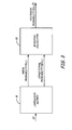
- FIG. 1 is block diagram illustrating identification of sub-module failure by a diagnostic tool based on error codes according to an embodiment of the present invention.
- FIG. 2 is a table illustrating an exemplary embodiment of a likelihood matrix employed by the diagnostic tool according to an embodiment of the present invention.
- FIG. 3 is a flow diagram illustrating operations performed by the diagnostic tool to generate posterior probabilities of sub-module failure based on a given error code (EC) according to an embodiment of the present invention.
- EC error code
- the present invention provides a Bayesian approach to identifying failed sub-modules.
- the Bayesian approach calculates probabilities of failure for each sub-module (i.e., posterior probabilities) based on prior probabilities of failure and likelihood data correlating the probability of sub-module failure generating a particular error code.
- a lambda-smoothing algorithm is employed to generate prior probabilities of failure given limited observed data.
- FIG. 1 is block diagram illustrating identification of sub-module failure by diagnostic tool 10 within system 12 according to an exemplary embodiment.
- System 12 includes built-in test (BIT) system 14 and a plurality of sub-modules U 1 , U 2 , ... U N .
- Each sub-module U 1 - U N includes one or more sensors generically labeled S.
- BIT system 14 sends/receives signals to/from the plurality of sensors S.
- OOR out-of-range
- BIT system 14 In response to out-of-range (OOR) sensor outputs, BIT system 14 generates one or more error codes (EC).
- EC error codes
- a temperature sensor provides an out-of-range signal to BIT system 14, which in turn generates a specific error code or codes.
- the term 'error code' refers generally to any output provided by BIT system 14 related to the status and/or health of system 12.
- external diagnostic tool 10 includes an input for receiving error codes generated by BIT system 14. Communication between BIT system 14 and external diagnostic tool 10 may employ wireless and/or wired communication protocols, or may allow for error codes displayed by BIT system 14 to be manually entered into diagnostic tool 10. In other embodiments, rather than configuring diagnostic tool 10 external to system 12, diagnostic tool 10 is included as part of system 12, either as a stand-alone module or as part of BIT system 14.
- Diagnostic tool 10 includes a combination of hardware and software for identifying failed sub-modules, including memory 16 for storing likelihood matrix 18 and algorithms associated with Bayesian calculator 20 and a processor 22 for executing the stored algorithms to identify the failed sub-module.
- the memory 16 can be any type of computer-readable storage medium known in the art, such as random access memory, nonvolatile memory, programmable read-only memory, a hard disk device, and the like.
- the processor 22 can be any type of processing circuitry capable of executing instructions, such as a general purpose processor, digital signal processor, microcontroller, programmable logic device, application specific integrated circuit, and the like.
- processor 22 executes a Bayesian algorithm to generate posterior probabilities associated with failure of each sub-module U 1 - U N based on the ECs provided by BIT system 14, and ultimately to provide an output identifying the likely failed sub-module.
- the output provided by diagnostic tool 10 prioritizes the likelihood of failure of each sub-module U 1 - U N (e.g., a list ordered to indicate the most likely failed sub-modules).
- the output provided by diagnostic tool 10 may be provided in various forms, including being provided on a display included on diagnostic tool 10, as part of a print-out provided by diagnostic tool 10, or as an electronic communication provided by diagnostic tool 10 to another system.
- a technician will replace/repair the identified sub-module.
- the benefit of this approach is the technician is provided the identity of the sub-module most likely to have failed, thereby reducing the amount of time the technician must spend troubleshooting the failed system 12.
- FIG. 2 is a table illustrating an exemplary embodiment of likelihood matrix 18 stored by diagnostic tool 10.
- Each column in likelihood matrix 18 represents a sub-module U 1 , U 2 , ... U N associated with system 12.
- Each row (except the last row) in the likelihood matrix 18 represents an error code (EC) that can be generated by BIT system 14.
- EC error code
- At the intersection of each row and column is the likelihood (i.e., conditional probability, P(E i
- the likelihoods for each intersection will be unique to each application, and are generated based on information known about system 12, the sub-modules U 1 , U 2 , ... U N , and the error codes (EC) generated.
- error code '2007' and sub-module U 1 For example, at the intersection of error code '2007' and sub-module U 1 is the likelihood value '0.4', which represents that a failure in sub-module U 1 should result in error code 2007 being generated forty percent of the time.
- the likelihood value '1' At the intersection of error code '2007' and sub-module 'U 2 ' is the likelihood value '1', which represents that a failure in sub-module U 2 should result in the generation of error code '2007' in every instance (i.e., one-hundred percent of the time).
- the converse assumption is not true. That is, the presence of error code '2007' does not represent with one-hundred percent certainty that sub-module U 2 has failed. For each cell labeled '0', a failure in the corresponding sub-module will never result in the associated error code being generated.
- the final row in likelihood matrix 18 represents the prior probabilities P(U j ) of failure associated with each sub-module.
- the prior probability P(U 1 ) is equal to '0.07', meaning that seven percent of the time sub-module U 1 has been estimated as the cause of system failure.
- the prior probability P(U 2 ) is equal to '0.01', meaning that only one percent of the time has sub-module U 2 been estimated as the cause of system failure.
- Equation 2 has the tendency to overestimate the probability of failure for those sub-modules that have not yet been observed to fail. For example, if there have been only two observed failures, both due to sub-module U 1 , the above equation would generate an estimated prior probability of failure P(U 1) of approximately 0.16, and a prior probability of failure for the remaining sixteen sub-modules of 0.035.
- Equation 3 provides a prior probability of failure P(U 1 ) for sub-module U 1 of 0.69 (i.e., 69%), and a prior probability of failure for the remaining sixteen sub-modules of 0.020 (i.e., 2%).
- a benefit of the lambda-smoothing algorithm is the ability to generate useful prior probabilities of failure P(U j ) for each sub-module based on limited amount of observational data. In particular, applications in which only limited numbers of systems are employed in the field (i.e., tens or hundreds), observational data will remain limited for a long period of time.
- Likelihood matrix 18 therefore includes conditional probabilities P(E ⁇
- U j ) corresponding to the provided error codes and prior probabilities P(U j ) stored by likelihood matrix 18 are selected and provided to Bayesian calculator 20.
- Bayesian calculator 20 calculates posterior probabilities of failure P(U j
- FIG. 3 is a flow diagram illustrating the algorithm executed by processor 22 (shown in FIG. 1 ) operations performed by diagnostic tool 10 to generate a posterior probability P(U j
- U j ) are selected by likelihood matrix 18, and are provided together with prior probabilities P(U j ) to Bayesian calculator 20.
- Bayesian calculator 20 calculates a posterior probability of failure P(U j
- Bayesian calculator 20 employs Bayes' law to generate the posterior probability of failure for each sub-module U 1 - U N of FIG. 1 .
- failed arg max P U j
- E ⁇ P E ⁇
- the term ⁇ is the set of error codes (EC) received from BIT system 14. The set may include one or a plurality of error codes.
- argmax represents that the sub-module having the highest (i.e., maximum) posterior probability is identified as the failed sub-module.
- Equation 4 is a normalization term where P( ⁇ ) ⁇ ⁇ P( ⁇
- Equation 4 The right-hand side of Equation 4 is calculated by repeatedly applying Bayes' law on the error code sequence ⁇ as provided in Equation 5.
- E ⁇ P Uj ⁇ P E 1
- U j , E 1 , E 2 Equation 5 provides that error codes can be correlated with one another.
- U j , E 1 ) represents the joint probability that two error codes are generated given the failure of a particular sub-module.
- employment of bigrams is only practical in applications in which a large amount of observable data is available to provide correlation between the presence of multiple error codes. In applications in which limited observable data is available, unigram approximation is employed to improve the calculation of the posterior probability.
- Equation 6 The following examples are provided to illustrate application of Equation 6 with respect to sub-modules U 1 and U 2 .
- sub-module U 1 has failed and BIT system 14 generates a single error code '2007'.
- likelihood matrix 18 Based on the provided error code, likelihood matrix 18 provides the following conditional probability P(2007
- the posterior probability of failure associated with sub-module U 1 is calculated as the product of the conditional probability P(2007
- U 1 ) and the probability of failure P(U 1 ), or 0.07 * 0.4 0.028 (i.e., 2.8% chance that sub-module U 1 has failed).
- likelihood matrix 18 provides the conditional probability P(2007
- the posterior probability of failure associated with sub-module U 2 is calculated as the product of the conditional probability P(2007
- U 2 ) and the probability of failure P(U 2 ), or 1 * 0.01 0.01 (i.e., 1% chance that sub-module U 2 has failed).
- the posterior probability of failure of sub-module U 1 (2.8%) is greater than the posterior probability of failure of sub-module U 2 (1%), and diagnostic tool 16 correctly identifies sub-module U 1 as having failed.
- likelihood matrix 18 provides the following conditional probabilities P(2007
- U 1 ) 0.4, P(2008
- U 1 ) 0.4, and P(6001
- the posterior probability of failure associated with sub-module U 1 is calculated as the product of the conditional probabilities P(2007
- U 1 ) and the probability of failure P(U 1 ), or (0.4 * 0.4 * 0.2) * 0.07 0.0022 (i.e., 0.22% chance that sub-module U 1 has failed).
- likelihood matrix 18 provides the conditional probability P(2007
- U 2 ) 1, P(2008
- U 2 ) 1, and P(6001
- the posterior probability of failure associated with sub-module U 2 is calculated as the product of the conditional probability P(2007
- U 2 ) and the probability of failure P(U 2 ), or (1 * 1 * 1) * 0.01 0.01 (i.e., 1% chance that sub-module U 2 has failed).
- the posterior probability of failure of sub-module U 2 (1%) is greater than the posterior probability of failure of sub-module U 1 (0.22%), and diagnostic tool 10 correctly identifies sub-module U 2 as having failed.
- diagnostic tool 10 provides an output identifying the sub-module likely to have caused the failure.
- diagnostic tool 10 provides an output prioritizing the likelihood of failure associated with each sub-module.
- diagnostic tool 10 may be updated as required, including modifying the both the conditional probabilities and prior probabilities of failure stored by likelihood matrix 18 based on the additional observation data.
- likelihood matrix 18 may be expanded to account for new sub-modules. Because the Bayesian approach to calculating posterior probabilities relies on the product of the conditional probability and prior probability for each sub-module, new sub-modules can be accommodated by adding additional columns to likelihood matrix 18.
Landscapes
- General Physics & Mathematics (AREA)
- Engineering & Computer Science (AREA)
- Physics & Mathematics (AREA)
- Mathematical Physics (AREA)
- Evolutionary Computation (AREA)
- Artificial Intelligence (AREA)
- Mathematical Analysis (AREA)
- Mathematical Optimization (AREA)
- Algebra (AREA)
- Probability & Statistics with Applications (AREA)
- Pure & Applied Mathematics (AREA)
- Automation & Control Theory (AREA)
- Test And Diagnosis Of Digital Computers (AREA)
- Testing And Monitoring For Control Systems (AREA)
- Error Detection And Correction (AREA)
- Debugging And Monitoring (AREA)
Abstract
Description
- The present invention is related to diagnostic tools and in particular to diagnostic tools for identifying failed sub-modules in larger systems.
- Complex systems are typically comprised of a plurality of sub-modules. A failure in one or more of the sub-modules may prevent or degrade the performance of system. However, when a system fails it is not always clear which sub-module is at fault. To diagnose failures, each sub-module may include a plurality of sensors (e.g., sometimes, many hundreds of sensors). Outputs from the sensors are collected by a Built-in Test (BIT) system, and in response to one or more of the sensor signals being "out-of-range", an error code (EC) specific to the detected failure is generated.
- Based on the generated error code(s), a technician takes an "If... Then... Else" approach to diagnosing which sub-module has failed. That is, IF a specified error code is generated, THEN the technician replaces/tests a first sub-module, ELSE the technician replaces/tests another sub-module, and continues until the failed sub-module is detected. This is a time-consuming and expensive process.
- The present invention provides a method of identifying sub-module failure within a system having a plurality of sub-modules. The method includes receiving one or more error codes from the system. Based on the received error codes, likelihood values corresponding to a probability of a failed sub-module generating the received error code and prior probabilities of failure associated with each sub-module are selected from a likelihood matrix. A posterior probability of failure is calculated for each of the plurality of sub-modules based on the selected likelihood value and the prior probability of failure associated with each sub-module. The failed sub-module is identified based on the calculated posterior probabilities.
- A diagnostic device for identifying failed sub-modules within a system includes an input for receiving errors codes from the system, a memory device, and a processor. The memory stores a likelihood matrix that correlates each sub-module with each possible error code and maintains a likelihood value corresponding to the probability of a failed sub-module generating a corresponding error code and stores a prior probability of failure associated with each sub-module based on prior observational data. The processor device executes an algorithm that calculates a posterior probability of failure for each of the plurality of sub-modules based on a product of the likelihood values corresponding to the received error codes and the prior probability of failure associated with each sub-module. Based on the posterior probabilities calculated with respect to each sub-module, the processor device generates an output identifying the sub-module with the highest posterior probability of failure as the failed sub-module.
-
FIG. 1 is block diagram illustrating identification of sub-module failure by a diagnostic tool based on error codes according to an embodiment of the present invention. -
FIG. 2 is a table illustrating an exemplary embodiment of a likelihood matrix employed by the diagnostic tool according to an embodiment of the present invention. -
FIG. 3 is a flow diagram illustrating operations performed by the diagnostic tool to generate posterior probabilities of sub-module failure based on a given error code (EC) according to an embodiment of the present invention. - The present invention provides a Bayesian approach to identifying failed sub-modules. The Bayesian approach calculates probabilities of failure for each sub-module (i.e., posterior probabilities) based on prior probabilities of failure and likelihood data correlating the probability of sub-module failure generating a particular error code. In particular, a lambda-smoothing algorithm is employed to generate prior probabilities of failure given limited observed data.
-
FIG. 1 is block diagram illustrating identification of sub-module failure bydiagnostic tool 10 withinsystem 12 according to an exemplary embodiment.System 12 includes built-in test (BIT)system 14 and a plurality of sub-modules U1, U2, ... UN. Each sub-module U1 - UN includes one or more sensors generically labeledS. BIT system 14 sends/receives signals to/from the plurality of sensors S. In response to out-of-range (OOR) sensor outputs,BIT system 14 generates one or more error codes (EC). For example, in one embodiment a temperature sensor provides an out-of-range signal toBIT system 14, which in turn generates a specific error code or codes. However, the term 'error code' refers generally to any output provided byBIT system 14 related to the status and/or health ofsystem 12. - Although based on inputs received from sensors local to various sub-modules, the error codes do not necessarily indicate the sub-module that has failed. In the embodiment shown in
FIG. 1 , externaldiagnostic tool 10 includes an input for receiving error codes generated byBIT system 14. Communication betweenBIT system 14 and externaldiagnostic tool 10 may employ wireless and/or wired communication protocols, or may allow for error codes displayed byBIT system 14 to be manually entered intodiagnostic tool 10. In other embodiments, rather than configuringdiagnostic tool 10 external tosystem 12,diagnostic tool 10 is included as part ofsystem 12, either as a stand-alone module or as part ofBIT system 14. -
Diagnostic tool 10 includes a combination of hardware and software for identifying failed sub-modules, includingmemory 16 for storinglikelihood matrix 18 and algorithms associated with Bayesiancalculator 20 and aprocessor 22 for executing the stored algorithms to identify the failed sub-module. Thememory 16 can be any type of computer-readable storage medium known in the art, such as random access memory, nonvolatile memory, programmable read-only memory, a hard disk device, and the like. Theprocessor 22 can be any type of processing circuitry capable of executing instructions, such as a general purpose processor, digital signal processor, microcontroller, programmable logic device, application specific integrated circuit, and the like. In one embodiment,processor 22 executes a Bayesian algorithm to generate posterior probabilities associated with failure of each sub-module U1 - UN based on the ECs provided byBIT system 14, and ultimately to provide an output identifying the likely failed sub-module. In other embodiments, the output provided bydiagnostic tool 10 prioritizes the likelihood of failure of each sub-module U1 - UN (e.g., a list ordered to indicate the most likely failed sub-modules). The output provided bydiagnostic tool 10 may be provided in various forms, including being provided on a display included ondiagnostic tool 10, as part of a print-out provided bydiagnostic tool 10, or as an electronic communication provided bydiagnostic tool 10 to another system. Based on the identification of the likely failed sub-module, a technician will replace/repair the identified sub-module. The benefit of this approach is the technician is provided the identity of the sub-module most likely to have failed, thereby reducing the amount of time the technician must spend troubleshooting the failedsystem 12. -
FIG. 2 is a table illustrating an exemplary embodiment oflikelihood matrix 18 stored bydiagnostic tool 10. Each column inlikelihood matrix 18 represents a sub-module U1, U2, ... UN associated withsystem 12. Each row (except the last row) in thelikelihood matrix 18 represents an error code (EC) that can be generated byBIT system 14. At the intersection of each row and column is the likelihood (i.e., conditional probability, P(Ei|Uj)) that a given error code Ei is generated when the corresponding sub-module Uj has failed. The likelihoods for each intersection will be unique to each application, and are generated based on information known aboutsystem 12, the sub-modules U1, U2, ... UN, and the error codes (EC) generated. For example, at the intersection of error code '2007' and sub-module U1 is the likelihood value '0.4', which represents that a failure in sub-module U1 should result inerror code 2007 being generated forty percent of the time. At the intersection of error code '2007' and sub-module 'U2' is the likelihood value '1', which represents that a failure in sub-module U2 should result in the generation of error code '2007' in every instance (i.e., one-hundred percent of the time). However, the converse assumption is not true. That is, the presence of error code '2007' does not represent with one-hundred percent certainty that sub-module U2 has failed. For each cell labeled '0', a failure in the corresponding sub-module will never result in the associated error code being generated. - The final row in
likelihood matrix 18 represents the prior probabilities P(Uj) of failure associated with each sub-module. For example, with respect to sub-module U1 the prior probability P(U1) is equal to '0.07', meaning that seven percent of the time sub-module U1 has been estimated as the cause of system failure. With respect to sub-module U2 the prior probability P(U2) is equal to '0.01', meaning that only one percent of the time has sub-module U2 been estimated as the cause of system failure. - Various methods exist for estimating prior probability values based on observational data. In each case, additional observations improve the accuracy of prior probability values. In instances in which limited observational data is available, estimation of prior probabilities may lead to either over-estimating the probability of failure or underestimating the probability of failure. For example, one method of estimating prior probabilities is based only on the number of times a particular sub-module has been observed to fail and the total number of observed failure of
system 12.
InEquation 1, P(Uj) is the estimated prior probability, c(Uj) is the number of times a given sub-module has failed, and N is the total number of failures experienced by the instrument. In instances, in which a given sub-module has never been observed to fail (i.e., c(Uj) = 0), the calculated prior probability will underestimate the likelihood of the sub-module failing as zero. - This problem can be remedied by simply adding one to the count of each sub-module, as provided in Equation 2,

where V is the total number of modules in the instrument that could possibly fail. In the example provided inFIG. 2 , V would be set equal to seventeen. However, for systems with small sets of observable data, Equation 2 has the tendency to overestimate the probability of failure for those sub-modules that have not yet been observed to fail. For example, if there have been only two observed failures, both due to sub-module U1, the above equation would generate an estimated prior probability of failure P(U1) of approximately 0.16, and a prior probability of failure for the remaining sixteen sub-modules of 0.035. This would suggest that subsequent failures are only about five times more likely to be due to sub-module U1 as opposed to another of the sub-modules, but intuition tells us that subsequent failures are much more likely to be due to sub-module U1 than any other module. - To remedy these problems, a lambda-smoothing algorithm is employed as provided in Equation 3,

where Vs is the total number of different (unique) sub-modules that have been observed previously to have failed. Using the same example provided with respect to Equation 2, in which two observed failures were both attributed to sub-module U1, then Equation 3 provides a prior probability of failure P(U1) for sub-module U1 of 0.69 (i.e., 69%), and a prior probability of failure for the remaining sixteen sub-modules of 0.020 (i.e., 2%). This agrees with our intuition that based on the observed data, subsequent failures are more likely to be caused by sub-module U1. A benefit of the lambda-smoothing algorithm is the ability to generate useful prior probabilities of failure P(Uj) for each sub-module based on limited amount of observational data. In particular, applications in which only limited numbers of systems are employed in the field (i.e., tens or hundreds), observational data will remain limited for a long period of time. -
Likelihood matrix 18 therefore includes conditional probabilities P(E¡|Uj) regarding the likelihood that a particular error code Ei is generated when a given sub-module Uj has failed, as well as prior probabilities P(Uj) that estimate the likelihood that sub-module Uj is the cause of instrument failure. Given a set of error codes provided byBIT system 14, conditional probabilities P(Ei|Uj) corresponding to the provided error codes and prior probabilities P(Uj) stored bylikelihood matrix 18 are selected and provided toBayesian calculator 20. Based on the selected conditional probabilities P(Ei|Uj) and prior probabilities P(Uj),Bayesian calculator 20 calculates posterior probabilities of failure P(Uj|Ei) for each sub-module. Based on the calculated posterior probabilities of failure P(Uj|Ei), the sub-module most likely to have failed is identified. -
FIG. 3 is a flow diagram illustrating the algorithm executed by processor 22 (shown inFIG. 1 ) operations performed bydiagnostic tool 10 to generate a posterior probability P(Uj|Ei) of sub-module failure based on a given error code (EC) according to an embodiment of the present invention. In response to error codes (EC) provided byBIT system 14, conditional probabilities P(Ei|Uj) are selected bylikelihood matrix 18, and are provided together with prior probabilities P(Uj) toBayesian calculator 20. In response to the selected conditional probabilities P(Ei|Uj) and the prior probability of failure P(Uj) provided bylikelihood matrix 18,Bayesian calculator 20 calculates a posterior probability of failure P(Uj|E) associated with each sub-module given the specified error code EC.Bayesian calculator 20 then selects the sub-module calculated to have the greatest posterior probability for failure given the specified error code and provides as an output the identified sub-module. - In one embodiment,
Bayesian calculator 20 employs Bayes' law to generate the posterior probability of failure for each sub-module U1 - UN ofFIG. 1 .
The term Ê is the set of error codes (EC) received fromBIT system 14. The set may include one or a plurality of error codes. The term argmax represents that the sub-module having the highest (i.e., maximum) posterior probability is identified as the failed sub-module. The term P(E) is a normalization term where P(Ê) ≡ Σ P(Ê|Uj)P(Uj). This term is the same for each sub-module U1 - UN, so it can be ignored for purposes of classifying which sub-module is most likely to be the cause of the system failure given the set of observed error codes. The right-hand side of Equation 4 is calculated by repeatedly applying Bayes' law on the error code sequence Ê as provided inEquation 5.
Equation 5 provides that error codes can be correlated with one another. For example, the bigram term P(E2 | Uj, E1) represents the joint probability that two error codes are generated given the failure of a particular sub-module. However, employment of bigrams is only practical in applications in which a large amount of observable data is available to provide correlation between the presence of multiple error codes. In applications in which limited observable data is available, unigram approximation is employed to improve the calculation of the posterior probability.
The proportional symbol '∼' indicates that the normalizing term P(Ê) is being ignored as described above, and that the product is over all error codes Ei in the observed set of error codes Ê. - The following examples are provided to illustrate application of Equation 6 with respect to sub-modules U1 and U2. For example, assume that sub-module U1 has failed and
BIT system 14 generates a single error code '2007'. Based on the provided error code,likelihood matrix 18 provides the following conditional probability P(2007|U1) = 0.4, and prior probability of failure P(U1) = 0.07 with respect to sub-module U1. Based on Equation 6, the posterior probability of failure associated with sub-module U1 is calculated as the product of the conditional probability P(2007|U1) and the probability of failure P(U1), or 0.07 * 0.4 = 0.028 (i.e., 2.8% chance that sub-module U1 has failed). Similarly, with respect to sub-module U2,likelihood matrix 18 provides the conditional probability P(2007|U2) = 1, and prior probability of failure P(U1) = 0.01. Based on Equation 6, the posterior probability of failure associated with sub-module U2 is calculated as the product of the conditional probability P(2007|U2) and the probability of failure P(U2), or 1 * 0.01 = 0.01 (i.e., 1% chance that sub-module U2 has failed). In this example, the posterior probability of failure of sub-module U1 (2.8%) is greater than the posterior probability of failure of sub-module U2 (1%), anddiagnostic tool 16 correctly identifies sub-module U1 as having failed. - Now, assume that sub-module U2 has failed and
BIT system 14 generates the set of error codes {2007,2008,6001}. Based on the provided error codes,likelihood matrix 18 provides the following conditional probabilities P(2007|U1) = 0.4, P(2008|U1) = 0.4, and P(6001|U1) = 0.2 and prior probability of failure P(U1) = 0.07 with respect to sub-module U1. Based on Equation 6, the posterior probability of failure associated with sub-module U1 is calculated as the product of the conditional probabilities P(2007|U1), P(2008|U1), P(6001|U1) and the probability of failure P(U1), or (0.4 * 0.4 * 0.2) * 0.07 = 0.0022 (i.e., 0.22% chance that sub-module U1 has failed). Similarly, with respect to sub-module U2,likelihood matrix 18 provides the conditional probability P(2007|U2) = 1, P(2008|U2) = 1, and P(6001|U2) = 1 and prior probability of failure P(U1) = 0.01. Based on Equation 6, the posterior probability of failure associated with sub-module U2 is calculated as the product of the conditional probability P(2007|U2), P(2008|U2), and P(6001|U2) and the probability of failure P(U2), or (1 * 1 * 1) * 0.01 = 0.01 (i.e., 1% chance that sub-module U2 has failed). In this example, the posterior probability of failure of sub-module U2 (1%) is greater than the posterior probability of failure of sub-module U1 (0.22%), anddiagnostic tool 10 correctly identifies sub-module U2 as having failed. - In this way,
diagnostic tool 10 provides an output identifying the sub-module likely to have caused the failure. In other embodiments, rather than identifying a single sub-module likely to have failed,diagnostic tool 10 provides an output prioritizing the likelihood of failure associated with each sub-module. In addition,diagnostic tool 10 may be updated as required, including modifying the both the conditional probabilities and prior probabilities of failure stored bylikelihood matrix 18 based on the additional observation data. In addition,likelihood matrix 18 may be expanded to account for new sub-modules. Because the Bayesian approach to calculating posterior probabilities relies on the product of the conditional probability and prior probability for each sub-module, new sub-modules can be accommodated by adding additional columns tolikelihood matrix 18. - While the invention has been described with reference to an exemplary embodiment(s), it will be understood by those skilled in the art that various changes may be made and equivalents may be substituted for elements thereof without departing from the scope of the invention, which is defined by the claims. In addition, many modifications may be made to adapt a particular situation or material to the teachings of the invention without departing from the essential scope thereof. Therefore, it is intended that the invention not be limited to the particular embodiment(s) disclosed, but that the invention will include all embodiments falling within the scope of the appended claims.
Claims (11)
- A method of identifying sub-module failure within a system (12) having a plurality of sub-modules (U1 - UN), the method comprising:receiving one or more error codes (EC) from the system (12);selecting from a likelihood matrix (18) at least one likelihood value corresponding to a probability of a failed sub-module generating the received error code (EC) and a prior probability of failure associated with each sub-module;calculating a posterior probability of failure for each of the plurality of sub-modules based on the selected likelihood value and the prior probability of failure associated with each sub-module; andidentifying based on the calculated posterior probability associated with each sub-module the sub-module most likely to have failed, wherein the selecting, calculating, and identifying are performed by a diagnostic tool (10).
- The method of claim 1, wherein calculating the posterior probability of failure includes multiplying the likelihood values selected based on the received error codes (EC) with the prior probability of failure to generate the posterior probability of failure with respect to each sub-module.
- The method of claim 1 or 2, wherein calculating the posterior probability of failure is based on the equation P(U j |Ê) ∼ P(Uj)P(Ê| Uj) ≈ P(Uj) Π P(Ei |Uj), wherein P(Uj |Ê) is the posterior probability calculated for each sub-module Uj, P(Uj) is the prior probability of failure associated with each sub-module Uj , and P(E¡ |Uj) is the likelihood value corresponding to a probability of a failed sub-module generating the received error.
- The method of claim 1, 2 or 3, further including:calculating the prior probability of failure associated with each sub-module based on a lambda-smoothing equation

- A diagnostic device (10) for identifying failed sub-modules (U1 - UN) within a larger system (12), the diagnostic device (10) comprising:an input for receiving error codes (EC) from the system;a memory (16) for storing a likelihood matrix (18) that correlates each sub-module with each possible error code and maintains a likelihood value corresponding to the probability of a failed sub-module generating a corresponding error code and stores a prior probability of failure associated with each sub-module based on prior observational data; anda processor (22) for executing an algorithm that calculates a posterior probability of failure for each of the plurality of sub-modules based on a product of the likelihood values corresponding to the received error codes and the prior probability of failure associated with each sub-module, wherein the processor generates an output identifying the sub-module with the highest posterior probability of failure as the failed sub-module.
- The diagnostic device (10) of claim 5, wherein the output generated by the processor (22) includes an ordered list of possible sub-module failures based on the posterior probabilities of failure calculated for each of the plurality of sub-modules.
- The diagnostic device of claim 5 or 6, wherein the diagnostic device (10) is internal to the larger system (12).
- The diagnostic device of claim 5 or 6, wherein the diagnostic device (10) is external to the larger system (12).
- The diagnostic device (10) of claim 5, 6, 7 or 8 wherein the prior probabilities included in the likelihood matrix (18) are calculated with a lambda-smoothing algorithm that is based on a number of observed failures associated with a particular sub-module, a number of sub-modules included within the system (12), and a number of total observed failures associated with the system (12).
- The diagnostic device of claim 9, wherein the lambda-smoothing algorithm is defined by the equation

- The diagnostic device (10) of any of claims 5 to 10, wherein the posterior probability of failure for each sub-module is calculated based on a Bayesian method defined by the equation

Applications Claiming Priority (1)
| Application Number | Priority Date | Filing Date | Title |
|---|---|---|---|
| US12/727,437 US8458525B2 (en) | 2010-03-19 | 2010-03-19 | Bayesian approach to identifying sub-module failure |
Publications (2)
| Publication Number | Publication Date |
|---|---|
| EP2369435A1 true EP2369435A1 (en) | 2011-09-28 |
| EP2369435B1 EP2369435B1 (en) | 2013-04-03 |
Family
ID=44121653
Family Applications (1)
| Application Number | Title | Priority Date | Filing Date |
|---|---|---|---|
| EP10251785A Not-in-force EP2369435B1 (en) | 2010-03-19 | 2010-10-12 | Bayesian approach to identifying sub-module failure |
Country Status (3)
| Country | Link |
|---|---|
| US (1) | US8458525B2 (en) |
| EP (1) | EP2369435B1 (en) |
| JP (1) | JP5774880B2 (en) |
Families Citing this family (8)
| Publication number | Priority date | Publication date | Assignee | Title |
|---|---|---|---|---|
| US8458525B2 (en) * | 2010-03-19 | 2013-06-04 | Hamilton Sundstrand Space Systems International, Inc. | Bayesian approach to identifying sub-module failure |
| US20140033174A1 (en) * | 2012-07-29 | 2014-01-30 | International Business Machines Corporation | Software bug predicting |
| WO2016068769A1 (en) * | 2014-10-31 | 2016-05-06 | Telefonaktiebolaget L M Ericsson (Publ) | Transmission data signaling in a wireless communication network |
| DE112016007535T5 (en) * | 2016-12-21 | 2019-09-26 | Mitsubishi Electric Corporation | CONTROL DEVICE AND PROCESSING METHOD IN THE EVENT OF A MALFUNCTION OF THE CONTROL DEVICE |
| CN107272625B (en) * | 2017-07-12 | 2019-05-28 | 温州大学 | A kind of industrial process method for diagnosing faults based on bayesian theory |
| CN114841382A (en) * | 2022-04-14 | 2022-08-02 | 上海齐耀螺杆机械有限公司 | Equipment failure detection method, device and storage medium |
| US20250112815A1 (en) * | 2023-09-29 | 2025-04-03 | Netscout Systems, Inc. | Systems and methods for error code analytics in telecommunications networks |
| CN117648895B (en) * | 2024-01-26 | 2024-04-12 | 全智芯(上海)技术有限公司 | Failure analysis method and device, computer readable storage medium and terminal |
Citations (1)
| Publication number | Priority date | Publication date | Assignee | Title |
|---|---|---|---|---|
| WO2006105930A1 (en) * | 2005-04-06 | 2006-10-12 | Daimlerchrysler Ag | Diagnostic system for determining a weighted list of possible defective components on the basis of vehicle data and customer specifications |
Family Cites Families (16)
| Publication number | Priority date | Publication date | Assignee | Title |
|---|---|---|---|---|
| EP0654738B1 (en) * | 1993-11-23 | 1999-03-03 | Hewlett-Packard Company | Diagnostic system |
| US6219626B1 (en) * | 1998-09-08 | 2001-04-17 | Lockheed Corp | Automated diagnostic system |
| US7088255B2 (en) * | 2001-05-29 | 2006-08-08 | Westinghouse Electric Co, Llc | Health monitoring display system for a complex plant |
| US7027953B2 (en) * | 2002-12-30 | 2006-04-11 | Rsl Electronics Ltd. | Method and system for diagnostics and prognostics of a mechanical system |
| US7158958B2 (en) * | 2003-12-24 | 2007-01-02 | The Boeing Company | Automatic generation of baysian diagnostics from fault trees |
| US7584382B2 (en) * | 2004-02-19 | 2009-09-01 | Microsoft Corporation | Method and system for troubleshooting a misconfiguration of a computer system based on configurations of other computer systems |
| US7260501B2 (en) * | 2004-04-21 | 2007-08-21 | University Of Connecticut | Intelligent model-based diagnostics for system monitoring, diagnosis and maintenance |
| JP2006338157A (en) * | 2005-05-31 | 2006-12-14 | Nippon Telegr & Teleph Corp <Ntt> | Document group processing apparatus, document group processing method, document group processing program, and recording medium storing document group processing program |
| US8126577B2 (en) * | 2005-06-03 | 2012-02-28 | Neophotonics Corporation | Monitoring and control of electronic devices |
| US7558771B2 (en) * | 2006-06-07 | 2009-07-07 | Gm Global Technology Operations, Inc. | System and method for selection of prediction tools |
| JP2008052376A (en) * | 2006-08-22 | 2008-03-06 | Fuji Xerox Co Ltd | Image forming apparatus, failure diagnostic system and fault diagnostic program |
| US8165705B2 (en) * | 2008-07-10 | 2012-04-24 | Palo Alto Research Center Incorporated | Methods and systems for continuously estimating persistent and intermittent failure probabilities for production resources |
| WO2010011918A2 (en) | 2008-07-24 | 2010-01-28 | University Of Cincinnati | Methods for prognosing mechanical systems |
| US8171343B2 (en) * | 2009-06-16 | 2012-05-01 | Oracle International Corporation | Techniques for determining models for performing diagnostics |
| US8411577B2 (en) * | 2010-03-19 | 2013-04-02 | At&T Intellectual Property I, L.P. | Methods, apparatus and articles of manufacture to perform root cause analysis for network events |
| US8458525B2 (en) * | 2010-03-19 | 2013-06-04 | Hamilton Sundstrand Space Systems International, Inc. | Bayesian approach to identifying sub-module failure |
-
2010
- 2010-03-19 US US12/727,437 patent/US8458525B2/en not_active Expired - Fee Related
- 2010-10-12 EP EP10251785A patent/EP2369435B1/en not_active Not-in-force
-
2011
- 2011-03-17 JP JP2011058659A patent/JP5774880B2/en not_active Expired - Fee Related
Patent Citations (1)
| Publication number | Priority date | Publication date | Assignee | Title |
|---|---|---|---|---|
| WO2006105930A1 (en) * | 2005-04-06 | 2006-10-12 | Daimlerchrysler Ag | Diagnostic system for determining a weighted list of possible defective components on the basis of vehicle data and customer specifications |
Non-Patent Citations (1)
| Title |
|---|
| BOSTROM H ED - ANONYMOUS: "Estimating Class Probabilities in Random Forests", MACHINE LEARNING AND APPLICATIONS, 2007. ICMLA 2007. SIXTH INTERNATIONAL CONFERENCE ON, IEEE, PISCATAWAY, NJ, USA, 13 December 2007 (2007-12-13), pages 211 - 216, XP031233714, ISBN: 978-0-7695-3069-7 * |
Also Published As
| Publication number | Publication date |
|---|---|
| US20110231703A1 (en) | 2011-09-22 |
| JP2011199867A (en) | 2011-10-06 |
| EP2369435B1 (en) | 2013-04-03 |
| JP5774880B2 (en) | 2015-09-09 |
| US8458525B2 (en) | 2013-06-04 |
Similar Documents
| Publication | Publication Date | Title |
|---|---|---|
| EP2369435B1 (en) | Bayesian approach to identifying sub-module failure | |
| US8498776B2 (en) | Fault diagnosis and prognosis using diagnostic trouble code markov chains | |
| EP2221698B1 (en) | Method for computing the relative likelihood of failures | |
| US8175846B2 (en) | Fault splitting algorithm | |
| JP6772491B2 (en) | Failure diagnosis device, failure diagnosis system, failure diagnosis method, and program | |
| JP6658250B2 (en) | Error diagnosis method, error diagnosis device, and error diagnosis program | |
| US7877636B2 (en) | System and method for detecting temporal relationships uniquely associated with an underlying root cause | |
| US20200026590A1 (en) | Component failure prediction | |
| EP3444724B1 (en) | Method and system for health monitoring and fault signature identification | |
| JP2017076360A (en) | Systems and methods for predictive reliability mining | |
| EP2555114A1 (en) | Systems and methods for using a corrective action as diagnostic evidence | |
| JP6062933B2 (en) | System and method for determining the optimal QC method for immediate submission results | |
| JP6164311B1 (en) | Information processing apparatus, information processing method, and program | |
| CN111124732A (en) | Disk fault prediction method, system, device and storage medium | |
| JP2022072229A (en) | Equipment diagnostic system, equipment diagnostic method and program | |
| US11080161B2 (en) | Control device, and processing method in event of failure in control device | |
| US20180011479A1 (en) | Error diagnosis method and error diagnosis system | |
| WO2022034633A1 (en) | Learning system, learning method, and program | |
| Yashchin | On detection of changes in categorical data | |
| EP3163463A1 (en) | A correlation estimating device and the related method | |
| Rachidi et al. | Moving average control chart for the detection and isolation of temporal faults in stochastic Petri nets | |
| EP4718179A1 (en) | Computer-implemented method for determining a yield of a manufacturing process for manufacturing of a product | |
| US20240190591A1 (en) | Detection device | |
| CN121058029A (en) | Information processing device, information processing method and information processing program | |
| Parreaux | Selective Monitoring Without Delay for Probabilistic System |
Legal Events
| Date | Code | Title | Description |
|---|---|---|---|
| PUAI | Public reference made under article 153(3) epc to a published international application that has entered the european phase |
Free format text: ORIGINAL CODE: 0009012 |
|
| AK | Designated contracting states |
Kind code of ref document: A1 Designated state(s): AL AT BE BG CH CY CZ DE DK EE ES FI FR GB GR HR HU IE IS IT LI LT LU LV MC MK MT NL NO PL PT RO RS SE SI SK SM TR |
|
| AX | Request for extension of the european patent |
Extension state: BA ME |
|
| 17P | Request for examination filed |
Effective date: 20120328 |
|
| GRAP | Despatch of communication of intention to grant a patent |
Free format text: ORIGINAL CODE: EPIDOSNIGR1 |
|
| GRAS | Grant fee paid |
Free format text: ORIGINAL CODE: EPIDOSNIGR3 |
|
| GRAA | (expected) grant |
Free format text: ORIGINAL CODE: 0009210 |
|
| AK | Designated contracting states |
Kind code of ref document: B1 Designated state(s): AL AT BE BG CH CY CZ DE DK EE ES FI FR GB GR HR HU IE IS IT LI LT LU LV MC MK MT NL NO PL PT RO RS SE SI SK SM TR |
|
| REG | Reference to a national code |
Ref country code: GB Ref legal event code: FG4D |
|
| REG | Reference to a national code |
Ref country code: AT Ref legal event code: REF Ref document number: 605088 Country of ref document: AT Kind code of ref document: T Effective date: 20130415 Ref country code: CH Ref legal event code: EP |
|
| REG | Reference to a national code |
Ref country code: IE Ref legal event code: FG4D |
|
| REG | Reference to a national code |
Ref country code: DE Ref legal event code: R096 Ref document number: 602010005897 Country of ref document: DE Effective date: 20130529 |
|
| REG | Reference to a national code |
Ref country code: SE Ref legal event code: TRGR |
|
| REG | Reference to a national code |
Ref country code: AT Ref legal event code: MK05 Ref document number: 605088 Country of ref document: AT Kind code of ref document: T Effective date: 20130403 |
|
| PG25 | Lapsed in a contracting state [announced via postgrant information from national office to epo] |
Ref country code: SI Free format text: LAPSE BECAUSE OF FAILURE TO SUBMIT A TRANSLATION OF THE DESCRIPTION OR TO PAY THE FEE WITHIN THE PRESCRIBED TIME-LIMIT Effective date: 20130403 |
|
| REG | Reference to a national code |
Ref country code: NL Ref legal event code: VDEP Effective date: 20130403 |
|
| REG | Reference to a national code |
Ref country code: LT Ref legal event code: MG4D |
|
| PG25 | Lapsed in a contracting state [announced via postgrant information from national office to epo] |
Ref country code: BE Free format text: LAPSE BECAUSE OF FAILURE TO SUBMIT A TRANSLATION OF THE DESCRIPTION OR TO PAY THE FEE WITHIN THE PRESCRIBED TIME-LIMIT Effective date: 20130403 Ref country code: FI Free format text: LAPSE BECAUSE OF FAILURE TO SUBMIT A TRANSLATION OF THE DESCRIPTION OR TO PAY THE FEE WITHIN THE PRESCRIBED TIME-LIMIT Effective date: 20130403 Ref country code: AT Free format text: LAPSE BECAUSE OF FAILURE TO SUBMIT A TRANSLATION OF THE DESCRIPTION OR TO PAY THE FEE WITHIN THE PRESCRIBED TIME-LIMIT Effective date: 20130403 Ref country code: IS Free format text: LAPSE BECAUSE OF FAILURE TO SUBMIT A TRANSLATION OF THE DESCRIPTION OR TO PAY THE FEE WITHIN THE PRESCRIBED TIME-LIMIT Effective date: 20130803 Ref country code: NL Free format text: LAPSE BECAUSE OF FAILURE TO SUBMIT A TRANSLATION OF THE DESCRIPTION OR TO PAY THE FEE WITHIN THE PRESCRIBED TIME-LIMIT Effective date: 20130403 Ref country code: GR Free format text: LAPSE BECAUSE OF FAILURE TO SUBMIT A TRANSLATION OF THE DESCRIPTION OR TO PAY THE FEE WITHIN THE PRESCRIBED TIME-LIMIT Effective date: 20130704 Ref country code: ES Free format text: LAPSE BECAUSE OF FAILURE TO SUBMIT A TRANSLATION OF THE DESCRIPTION OR TO PAY THE FEE WITHIN THE PRESCRIBED TIME-LIMIT Effective date: 20130714 Ref country code: NO Free format text: LAPSE BECAUSE OF FAILURE TO SUBMIT A TRANSLATION OF THE DESCRIPTION OR TO PAY THE FEE WITHIN THE PRESCRIBED TIME-LIMIT Effective date: 20130703 Ref country code: PT Free format text: LAPSE BECAUSE OF FAILURE TO SUBMIT A TRANSLATION OF THE DESCRIPTION OR TO PAY THE FEE WITHIN THE PRESCRIBED TIME-LIMIT Effective date: 20130805 Ref country code: LT Free format text: LAPSE BECAUSE OF FAILURE TO SUBMIT A TRANSLATION OF THE DESCRIPTION OR TO PAY THE FEE WITHIN THE PRESCRIBED TIME-LIMIT Effective date: 20130403 |
|
| PG25 | Lapsed in a contracting state [announced via postgrant information from national office to epo] |
Ref country code: BG Free format text: LAPSE BECAUSE OF FAILURE TO SUBMIT A TRANSLATION OF THE DESCRIPTION OR TO PAY THE FEE WITHIN THE PRESCRIBED TIME-LIMIT Effective date: 20130703 Ref country code: CY Free format text: LAPSE BECAUSE OF FAILURE TO SUBMIT A TRANSLATION OF THE DESCRIPTION OR TO PAY THE FEE WITHIN THE PRESCRIBED TIME-LIMIT Effective date: 20130403 Ref country code: LV Free format text: LAPSE BECAUSE OF FAILURE TO SUBMIT A TRANSLATION OF THE DESCRIPTION OR TO PAY THE FEE WITHIN THE PRESCRIBED TIME-LIMIT Effective date: 20130403 Ref country code: RS Free format text: LAPSE BECAUSE OF FAILURE TO SUBMIT A TRANSLATION OF THE DESCRIPTION OR TO PAY THE FEE WITHIN THE PRESCRIBED TIME-LIMIT Effective date: 20130403 Ref country code: HR Free format text: LAPSE BECAUSE OF FAILURE TO SUBMIT A TRANSLATION OF THE DESCRIPTION OR TO PAY THE FEE WITHIN THE PRESCRIBED TIME-LIMIT Effective date: 20130403 Ref country code: PL Free format text: LAPSE BECAUSE OF FAILURE TO SUBMIT A TRANSLATION OF THE DESCRIPTION OR TO PAY THE FEE WITHIN THE PRESCRIBED TIME-LIMIT Effective date: 20130403 |
|
| PG25 | Lapsed in a contracting state [announced via postgrant information from national office to epo] |
Ref country code: DK Free format text: LAPSE BECAUSE OF FAILURE TO SUBMIT A TRANSLATION OF THE DESCRIPTION OR TO PAY THE FEE WITHIN THE PRESCRIBED TIME-LIMIT Effective date: 20130403 Ref country code: CZ Free format text: LAPSE BECAUSE OF FAILURE TO SUBMIT A TRANSLATION OF THE DESCRIPTION OR TO PAY THE FEE WITHIN THE PRESCRIBED TIME-LIMIT Effective date: 20130403 Ref country code: SK Free format text: LAPSE BECAUSE OF FAILURE TO SUBMIT A TRANSLATION OF THE DESCRIPTION OR TO PAY THE FEE WITHIN THE PRESCRIBED TIME-LIMIT Effective date: 20130403 Ref country code: EE Free format text: LAPSE BECAUSE OF FAILURE TO SUBMIT A TRANSLATION OF THE DESCRIPTION OR TO PAY THE FEE WITHIN THE PRESCRIBED TIME-LIMIT Effective date: 20130403 |
|
| PLBE | No opposition filed within time limit |
Free format text: ORIGINAL CODE: 0009261 |
|
| STAA | Information on the status of an ep patent application or granted ep patent |
Free format text: STATUS: NO OPPOSITION FILED WITHIN TIME LIMIT |
|
| PG25 | Lapsed in a contracting state [announced via postgrant information from national office to epo] |
Ref country code: RO Free format text: LAPSE BECAUSE OF FAILURE TO SUBMIT A TRANSLATION OF THE DESCRIPTION OR TO PAY THE FEE WITHIN THE PRESCRIBED TIME-LIMIT Effective date: 20130403 |
|
| PGFP | Annual fee paid to national office [announced via postgrant information from national office to epo] |
Ref country code: IT Payment date: 20131031 Year of fee payment: 4 |
|
| 26N | No opposition filed |
Effective date: 20140106 |
|
| REG | Reference to a national code |
Ref country code: DE Ref legal event code: R097 Ref document number: 602010005897 Country of ref document: DE Effective date: 20140106 |
|
| PG25 | Lapsed in a contracting state [announced via postgrant information from national office to epo] |
Ref country code: MC Free format text: LAPSE BECAUSE OF FAILURE TO SUBMIT A TRANSLATION OF THE DESCRIPTION OR TO PAY THE FEE WITHIN THE PRESCRIBED TIME-LIMIT Effective date: 20130403 |
|
| REG | Reference to a national code |
Ref country code: SE Ref legal event code: EUG |
|
| REG | Reference to a national code |
Ref country code: IE Ref legal event code: MM4A |
|
| REG | Reference to a national code |
Ref country code: FR Ref legal event code: ST Effective date: 20140630 |
|
| PG25 | Lapsed in a contracting state [announced via postgrant information from national office to epo] |
Ref country code: FR Free format text: LAPSE BECAUSE OF NON-PAYMENT OF DUE FEES Effective date: 20131031 Ref country code: SE Free format text: LAPSE BECAUSE OF NON-PAYMENT OF DUE FEES Effective date: 20131013 |
|
| PGFP | Annual fee paid to national office [announced via postgrant information from national office to epo] |
Ref country code: DE Payment date: 20131009 Year of fee payment: 4 |
|
| PG25 | Lapsed in a contracting state [announced via postgrant information from national office to epo] |
Ref country code: IE Free format text: LAPSE BECAUSE OF NON-PAYMENT OF DUE FEES Effective date: 20131012 |
|
| REG | Reference to a national code |
Ref country code: DE Ref legal event code: R119 Ref document number: 602010005897 Country of ref document: DE |
|
| PG25 | Lapsed in a contracting state [announced via postgrant information from national office to epo] |
Ref country code: SM Free format text: LAPSE BECAUSE OF FAILURE TO SUBMIT A TRANSLATION OF THE DESCRIPTION OR TO PAY THE FEE WITHIN THE PRESCRIBED TIME-LIMIT Effective date: 20130403 |
|
| REG | Reference to a national code |
Ref country code: CH Ref legal event code: PL |
|
| PG25 | Lapsed in a contracting state [announced via postgrant information from national office to epo] |
Ref country code: TR Free format text: LAPSE BECAUSE OF FAILURE TO SUBMIT A TRANSLATION OF THE DESCRIPTION OR TO PAY THE FEE WITHIN THE PRESCRIBED TIME-LIMIT Effective date: 20130403 |
|
| PG25 | Lapsed in a contracting state [announced via postgrant information from national office to epo] |
Ref country code: MK Free format text: LAPSE BECAUSE OF FAILURE TO SUBMIT A TRANSLATION OF THE DESCRIPTION OR TO PAY THE FEE WITHIN THE PRESCRIBED TIME-LIMIT Effective date: 20130403 Ref country code: HU Free format text: LAPSE BECAUSE OF FAILURE TO SUBMIT A TRANSLATION OF THE DESCRIPTION OR TO PAY THE FEE WITHIN THE PRESCRIBED TIME-LIMIT; INVALID AB INITIO Effective date: 20101012 Ref country code: DE Free format text: LAPSE BECAUSE OF NON-PAYMENT OF DUE FEES Effective date: 20150501 Ref country code: LU Free format text: LAPSE BECAUSE OF NON-PAYMENT OF DUE FEES Effective date: 20131012 Ref country code: LI Free format text: LAPSE BECAUSE OF NON-PAYMENT OF DUE FEES Effective date: 20141031 Ref country code: CH Free format text: LAPSE BECAUSE OF NON-PAYMENT OF DUE FEES Effective date: 20141031 |
|
| PG25 | Lapsed in a contracting state [announced via postgrant information from national office to epo] |
Ref country code: IT Free format text: LAPSE BECAUSE OF NON-PAYMENT OF DUE FEES Effective date: 20141012 Ref country code: MT Free format text: LAPSE BECAUSE OF FAILURE TO SUBMIT A TRANSLATION OF THE DESCRIPTION OR TO PAY THE FEE WITHIN THE PRESCRIBED TIME-LIMIT Effective date: 20130403 |
|
| PG25 | Lapsed in a contracting state [announced via postgrant information from national office to epo] |
Ref country code: AL Free format text: LAPSE BECAUSE OF FAILURE TO SUBMIT A TRANSLATION OF THE DESCRIPTION OR TO PAY THE FEE WITHIN THE PRESCRIBED TIME-LIMIT Effective date: 20130403 |
|
| PGFP | Annual fee paid to national office [announced via postgrant information from national office to epo] |
Ref country code: GB Payment date: 20190923 Year of fee payment: 10 |
|
| GBPC | Gb: european patent ceased through non-payment of renewal fee |
Effective date: 20201012 |
|
| PG25 | Lapsed in a contracting state [announced via postgrant information from national office to epo] |
Ref country code: GB Free format text: LAPSE BECAUSE OF NON-PAYMENT OF DUE FEES Effective date: 20201012 |