EP2369389A1 - Optical fiber coating to prevent adhesion at high temperatures - Google Patents
Optical fiber coating to prevent adhesion at high temperatures Download PDFInfo
- Publication number
- EP2369389A1 EP2369389A1 EP11250364A EP11250364A EP2369389A1 EP 2369389 A1 EP2369389 A1 EP 2369389A1 EP 11250364 A EP11250364 A EP 11250364A EP 11250364 A EP11250364 A EP 11250364A EP 2369389 A1 EP2369389 A1 EP 2369389A1
- Authority
- EP
- European Patent Office
- Prior art keywords
- high temperature
- fibers
- cable
- temperature rated
- substance
- Prior art date
- Legal status (The legal status is an assumption and is not a legal conclusion. Google has not performed a legal analysis and makes no representation as to the accuracy of the status listed.)
- Granted
Links
Images



Classifications
-
- E—FIXED CONSTRUCTIONS
- E21—EARTH OR ROCK DRILLING; MINING
- E21B—EARTH OR ROCK DRILLING; OBTAINING OIL, GAS, WATER, SOLUBLE OR MELTABLE MATERIALS OR A SLURRY OF MINERALS FROM WELLS
- E21B47/00—Survey of boreholes or wells
- E21B47/12—Means for transmitting measuring-signals or control signals from the well to the surface, or from the surface to the well, e.g. for logging while drilling
- E21B47/13—Means for transmitting measuring-signals or control signals from the well to the surface, or from the surface to the well, e.g. for logging while drilling by electromagnetic energy, e.g. radio frequency
- E21B47/135—Means for transmitting measuring-signals or control signals from the well to the surface, or from the surface to the well, e.g. for logging while drilling by electromagnetic energy, e.g. radio frequency using light waves, e.g. infrared or ultraviolet waves
-
- B—PERFORMING OPERATIONS; TRANSPORTING
- B05—SPRAYING OR ATOMISING IN GENERAL; APPLYING FLUENT MATERIALS TO SURFACES, IN GENERAL
- B05D—PROCESSES FOR APPLYING FLUENT MATERIALS TO SURFACES, IN GENERAL
- B05D5/00—Processes for applying liquids or other fluent materials to surfaces to obtain special surface effects, finishes or structures
- B05D5/08—Processes for applying liquids or other fluent materials to surfaces to obtain special surface effects, finishes or structures to obtain an anti-friction or anti-adhesive surface
-
- G—PHYSICS
- G02—OPTICS
- G02B—OPTICAL ELEMENTS, SYSTEMS OR APPARATUS
- G02B6/00—Light guides; Structural details of arrangements comprising light guides and other optical elements, e.g. couplings
- G02B6/44—Mechanical structures for providing tensile strength and external protection for fibres, e.g. optical transmission cables
- G02B6/4401—Optical cables
- G02B6/4415—Cables for special applications
-
- G—PHYSICS
- G02—OPTICS
- G02B—OPTICAL ELEMENTS, SYSTEMS OR APPARATUS
- G02B6/00—Light guides; Structural details of arrangements comprising light guides and other optical elements, e.g. couplings
- G02B6/44—Mechanical structures for providing tensile strength and external protection for fibres, e.g. optical transmission cables
- G02B6/4401—Optical cables
- G02B6/4429—Means specially adapted for strengthening or protecting the cables
- G02B6/4436—Heat resistant
-
- G—PHYSICS
- G02—OPTICS
- G02B—OPTICAL ELEMENTS, SYSTEMS OR APPARATUS
- G02B6/00—Light guides; Structural details of arrangements comprising light guides and other optical elements, e.g. couplings
- G02B6/44—Mechanical structures for providing tensile strength and external protection for fibres, e.g. optical transmission cables
- G02B6/4479—Manufacturing methods of optical cables
- G02B6/4486—Protective covering
-
- G—PHYSICS
- G02—OPTICS
- G02B—OPTICAL ELEMENTS, SYSTEMS OR APPARATUS
- G02B6/00—Light guides; Structural details of arrangements comprising light guides and other optical elements, e.g. couplings
- G02B6/44—Mechanical structures for providing tensile strength and external protection for fibres, e.g. optical transmission cables
- G02B6/4479—Manufacturing methods of optical cables
- G02B6/4486—Protective covering
- G02B6/4488—Protective covering using metallic tubes
-
- Y—GENERAL TAGGING OF NEW TECHNOLOGICAL DEVELOPMENTS; GENERAL TAGGING OF CROSS-SECTIONAL TECHNOLOGIES SPANNING OVER SEVERAL SECTIONS OF THE IPC; TECHNICAL SUBJECTS COVERED BY FORMER USPC CROSS-REFERENCE ART COLLECTIONS [XRACs] AND DIGESTS
- Y10—TECHNICAL SUBJECTS COVERED BY FORMER USPC
- Y10T—TECHNICAL SUBJECTS COVERED BY FORMER US CLASSIFICATION
- Y10T29/00—Metal working
- Y10T29/49—Method of mechanical manufacture
- Y10T29/49826—Assembling or joining
- Y10T29/49885—Assembling or joining with coating before or during assembling
Definitions
- Embodiments of the present invention generally relate to cables for use in high temperature environments, such as downhole gas and oil well applications.
- FIG. 1 illustrates a schematic cross-sectional view of a wellbore 102, wherein a cable 110 is provided as a sensing device within the wellbore 102. Properties of downhole formations surrounding or otherwise adjacent the wellbore 102 may be monitored over time based on measurements made by the sensing device. Further, hydrocarbon production may be controlled or reservoirs 108 may be managed based on the downhole formation properties.
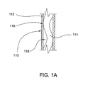
- FIG. 1A illustrates a partial sectional side view of the cable 110.
- Cables used in high temperature operations may be made by introducing excess fiber length (EFL) to avoid tension on the one or more fibers 114 at high temperatures due to thermal expansion of the cable components.
- the fibers 114 generally take on a sinusoidal and/or helical form inside the cable 110. As the fibers 114 and the cable 110 are not retained relative to one another, the sinusoidal orientation of the fibers 114 within the cable 110 may result in intermittent contact points 116 and gaps 118 therebetween.
- the EFL of the cable 110 may be reduced and coatings on the one or more fibers 114 may adhere at contact points with each other or to an inner wall of the cable 110 either through partial melting or chemical bonding of the coatings.
- Applications using Weatherford's standard downhole cables above 300 degrees Celsius may be near the melting point of the polyimide coatings used on the fibers. At 350 degrees Celsius, the coating on the fibers may become brittle.
- the cable structure contracts and the fibers 114 within the cable 110 may return to a state of increased EFL. If the fibers 114 are adhered with each other or to an inner wall of the cable 110, the fibers 114 may not return to their respective original orientations and tight bends may form along the fibers resulting in increased optical loss.
- Embodiments of the present invention generally provide methods and apparatus for cables having one or more fibers, wherein the fibers do not adhere to each other or to an inner wall of the cable during a high temperature operation.
- One embodiment of the present invention is a method.
- the method generally includes providing a tube plus one or more fibers, applying a high temperature rated substance to the one or more fibers, and deploying the one or more fibers into the tube to provide a cable, wherein the substance prevents the one or more fibers from adhering to each other or to an inner wall of the cable during a high temperature operation.
- Another embodiment of the present invention is a method.
- the method generally includes providing a cable with one or more fibers, and filling the cable with a high temperature rated substance, wherein the substance prevents the one or more fibers from adhering to each other or to an inner wall of the cable during a high temperature operation.
- Yet another embodiment of the present invention is a method.
- the method generally includes providing a cable with one or more fibers, and injecting a high temperature rated filler material into the cable, wherein the filler material fills void spaces within the cable surrounding the one or more fibers and prevents the one or more fibers from adhering to each other or to an inner wall of the cable during a high temperature operation.
- the cable generally includes a tube, one or more fibers disposed in the tube, and a high temperature rated substance disposed over the one or more fibers, wherein the one or more fibers do not adhere to each other or to an inner wall of the cable during the operation.
- Yet another embodiment of the present invention is a method.
- the method generally includes producing one or more fibers with a high temperature rated coating, and deploying the one or more fibers into a tube to provide a cable, wherein the coating prevents the one or more fibers from adhering to each other or to an inner wall of the cable during a high temperature operation.
- FIG. 1 is a schematic cross-sectional view of a wellbore, wherein a cable is provided as a sensing device within the wellbore, according to an embodiment of the present invention.
- FIG. 1A is a partial sectional side view of the cable of FIG. 1 , according to an embodiment of the present invention.
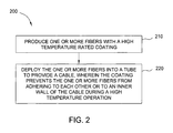
- FIG. 2 is a flow diagram of exemplary operations for providing a cable with one or more fibers, wherein the one or more fibers are produced with a high temperature rated coating, according to an embodiment of the present invention.
- FIG. 3 is a flow diagram of exemplary operations for providing a cable with one or more fibers, wherein a high temperature rated substance is applied to the one or more fibers prior to cabling, according to an embodiment of the present invention.
- FIG. 4 illustrates a simplified schematic of a cable assembly line corresponding to the example operation shown in FIG. 3 .
- FIG. 5 is a flow diagram of exemplary operations for providing a cable with one or more fibers, wherein the cable is filled with a high temperature rated substance, according to an embodiment of the present invention.
- FIG. 6 is a flow diagram of exemplary operations for providing a cable with one or more fibers, wherein the cable is injected with a high temperature rated filler material, according to an embodiment of the present invention.
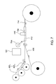
- FIG. 7 illustrates a simplified schematic of a cable assembly line corresponding to example operations shown in FIGs. 5 and 6 .
- Embodiments of the present invention provide methods and apparatus for cables having one or more fibers that may function as a sensing device within a wellbore, wherein the fibers do not adhere to each other or to an inner wall of the cable during a high temperature operation, such as in a thermal recovery operation that may last over 30 days with temperatures at or exceeding about 200 degrees Celsius (e.g., at least about 250 or at least about 300 degrees Celsius).
- FIG. 2 illustrates operations 200 for providing a cable with one or more fibers, wherein the one or more fibers are produced with a high temperature rated coating, according to embodiments of the present invention.
- one or more fibers may be produced with a high temperature rated coating.
- the high temperature rated coating may be a highly-cured polyimide coating.
- the coating may undergo an imidization reaction, promoted by heat, to cure the polyimide.
- the polyimide coating may not have fully reacted during the fiber coating process. Unreacted sites in the coating may be a source of the coated fibers adhering to one another when further exposed to heat.
- the highly-cured polyimide coating is one that is 100% or nearly 100% imidized (i.e., cured). Obtaining a highly-cured polyimide coating may be accomplished during the initial coating application with process adjustments (such as thermal dwell time and temperature) or in a post cure process using heat or infrared energy.
- the one or more fibers with the high temperature rated coating may be deployed into a tube to provide a cable, wherein the coating prevents the one or more fibers from adhering to each other or to an inner wall of the cable during a high temperature operation, such as in a thermal recovery operation that may have temperatures at or exceeding about 200 degrees Celsius.
- FIGs. 3-4 are a flow diagram and simplified schematic of operations 300 for providing a cable with one or more fibers, wherein a high temperature rated substance is applied to the one or more fibers prior to cabling, according to embodiments of the present invention.
- a tube 412 plus one or more fibers (402 1 ...402 n ) may be provided at 310.
- the tube 412 may be formed from a metal strip stock 408.
- the high temperature rated substance may be applied to the one or more fibers (402 1 ...402 n ) by an applicator 404.
- the high temperature rated substance may be at least a high temperature rated silicone oil, high temperature rated lubricant oil, a high temperature rated mold release agent, or the highly-cured polyimide coating.
- the high temperature rated substance may be applied by a wetted sponge or cloth, or a fine spray type applicator and the like.
- the high temperature rated substance may be applied by passing the one or more fibers (402 1 ...402 n ) through a bath of the high temperature rated substance and wiping the excess off.
- the high temperature rated substance may be applied to the one or more fibers (402 1 ...402 n ) offline so that the spools of the one or more fibers may already have the substance applied.
- the one or more fibers having the substance applied (406 1 ...406 n ) may be deployed into the tube 412 to provide the cable 414, wherein the high temperature rated substance prevents the one or more fibers (406 1 ...406 n ) from adhering to each other or to an inner wall of the cable 414 during a high temperature operation.
- the one or more fibers (406 1 ... 406 n ) may be sheathed in a seam welded tube 412 by a seam welder 410 to provide the cable 414.
- FIG. 5 illustrates operations 500 for providing a cable with one or more fibers, wherein the finished cable is filled with a high temperature rated substance, according to embodiments of the present invention.
- a cable with one or more fibers may be provided at 510.
- the one or more fibers (402 1 ...402 n ) may be sheathed in a seam-welded tube 412 by a seam welder 410.
- the cable may be filled with a high temperature rated substance, wherein the substance prevents the one or more fibers from adhering to each other or to an inner wall of the cable 714 during a high temperature operation.
- the high temperature rated substance may be at least a high temperature rated silicone oil, high temperature rated lubricant oil, a high temperature rated mold release agent, or the highly-cured polyimide coating.
- the high temperature rated substance may be fed through a hypodermic tube 706, which may run parallel to the cable.
- the high temperature rated substance may be contained in a reservoir 702 and fed through the hypodermic tube 706 by a metering pump 704. The substance may exit the tube 706 just downstream of the seam welder 410 as not to contaminate the welding process.
- the cable may be filled with the high temperature rated substance to only 50% - 75% capacity for some embodiments.
- an excess amount of the high temperature rated substance may be drained from the cable.
- the cable 714 may be loaded on a spool.
- FIG. 6 illustrates operations 600 for providing a cable with one or more fibers, wherein the finished cable is filled with a high temperature rated filler material, according to embodiments of the present invention.
- a cable with one or more fibers may be provided at 610.
- the one or more fibers (402 1 ...402 n ) may be sheathed in a seam-welded tube by a seam welder 410.
- the cable may be filled with a high temperature rated filler material, wherein the filler material fills void spaces within the cable surrounding the one or more fibers and prevents the one or more fibers from adhering to each other or to an inner wall of the cable during a high temperature operation.
- the filler material supports and prevents the one or more fibers (402 1 ...402 n ) from moving excessively within the cable 714.
- the filler material also prevents chaffing of the coatings on the one or more fibers (402 1 ...402 n ) as a result of bending action during installation and vibration of the cable 714.
- the filler material also serves to cushion the one or more fibers (402 1 ...402 n ) against the inner wall of the cable 714 to avoid microbend losses across cable bends.
- the high temperature rated filler material may be fed through a hypodermic tube 706, which may run parallel to the cable.
- the high temperature rated filler material may be contained in a reservoir 702 and fed through the hypodermic tube 706 by a metering pump 704.
- the filler material may exit the tube 706 just downstream of the seam welder 410 as not to contaminate the welding process.
- the cable 714 may be loaded on a spool.
Landscapes
- Physics & Mathematics (AREA)
- Engineering & Computer Science (AREA)
- General Physics & Mathematics (AREA)
- Optics & Photonics (AREA)
- Remote Sensing (AREA)
- Life Sciences & Earth Sciences (AREA)
- Geology (AREA)
- Mining & Mineral Resources (AREA)
- Manufacturing & Machinery (AREA)
- Electromagnetism (AREA)
- Geophysics (AREA)
- Environmental & Geological Engineering (AREA)
- Fluid Mechanics (AREA)
- General Life Sciences & Earth Sciences (AREA)
- Geochemistry & Mineralogy (AREA)
- Application Of Or Painting With Fluid Materials (AREA)
- Insulated Conductors (AREA)
Abstract
Description
- Embodiments of the present invention generally relate to cables for use in high temperature environments, such as downhole gas and oil well applications.
- With advancements in the area of fiber optic sensors for use in harsh environments, there is an increasing need for fiber optic cables compatible with the harsh environmental conditions present in downhole oil and gas well applications.
FIG. 1 illustrates a schematic cross-sectional view of awellbore 102, wherein acable 110 is provided as a sensing device within thewellbore 102. Properties of downhole formations surrounding or otherwise adjacent thewellbore 102 may be monitored over time based on measurements made by the sensing device. Further, hydrocarbon production may be controlled orreservoirs 108 may be managed based on the downhole formation properties. -
FIG. 1A illustrates a partial sectional side view of thecable 110. Cables used in high temperature operations, such as in a thermal recovery operation, may be made by introducing excess fiber length (EFL) to avoid tension on the one ormore fibers 114 at high temperatures due to thermal expansion of the cable components. Thefibers 114 generally take on a sinusoidal and/or helical form inside thecable 110. As thefibers 114 and thecable 110 are not retained relative to one another, the sinusoidal orientation of thefibers 114 within thecable 110 may result inintermittent contact points 116 andgaps 118 therebetween. - During a thermal recovery operation, the EFL of the
cable 110 may be reduced and coatings on the one ormore fibers 114 may adhere at contact points with each other or to an inner wall of thecable 110 either through partial melting or chemical bonding of the coatings. Applications using Weatherford's standard downhole cables above 300 degrees Celsius may be near the melting point of the polyimide coatings used on the fibers. At 350 degrees Celsius, the coating on the fibers may become brittle. After a thermal recovery operation, which may last over 30 days, when the cable temperature may then be reduced, the cable structure contracts and thefibers 114 within thecable 110 may return to a state of increased EFL. If thefibers 114 are adhered with each other or to an inner wall of thecable 110, thefibers 114 may not return to their respective original orientations and tight bends may form along the fibers resulting in increased optical loss. - Embodiments of the present invention generally provide methods and apparatus for cables having one or more fibers, wherein the fibers do not adhere to each other or to an inner wall of the cable during a high temperature operation.
- One embodiment of the present invention is a method. The method generally includes providing a tube plus one or more fibers, applying a high temperature rated substance to the one or more fibers, and deploying the one or more fibers into the tube to provide a cable, wherein the substance prevents the one or more fibers from adhering to each other or to an inner wall of the cable during a high temperature operation.
- Another embodiment of the present invention is a method. The method generally includes providing a cable with one or more fibers, and filling the cable with a high temperature rated substance, wherein the substance prevents the one or more fibers from adhering to each other or to an inner wall of the cable during a high temperature operation.
- Yet another embodiment of the present invention is a method. The method generally includes providing a cable with one or more fibers, and injecting a high temperature rated filler material into the cable, wherein the filler material fills void spaces within the cable surrounding the one or more fibers and prevents the one or more fibers from adhering to each other or to an inner wall of the cable during a high temperature operation.
- Yet another embodiment of the present invention provides a cable suitable for a high temperature operation. The cable generally includes a tube, one or more fibers disposed in the tube, and a high temperature rated substance disposed over the one or more fibers, wherein the one or more fibers do not adhere to each other or to an inner wall of the cable during the operation.
- Yet another embodiment of the present invention is a method. The method generally includes producing one or more fibers with a high temperature rated coating, and deploying the one or more fibers into a tube to provide a cable, wherein the coating prevents the one or more fibers from adhering to each other or to an inner wall of the cable during a high temperature operation.
- So that the manner in which the above-recited features of the present invention can be understood in detail, a more particular description of the invention, briefly summarized above, may be had by reference to embodiments, some of which are illustrated in the appended drawings. It is to be noted, however, that the appended drawings illustrate only typical embodiments of this invention and are therefore not to be considered limiting of its scope, for the invention may admit to other equally effective embodiments.
-
FIG. 1 is a schematic cross-sectional view of a wellbore, wherein a cable is provided as a sensing device within the wellbore, according to an embodiment of the present invention. -
FIG. 1A is a partial sectional side view of the cable ofFIG. 1 , according to an embodiment of the present invention. -
FIG. 2 is a flow diagram of exemplary operations for providing a cable with one or more fibers, wherein the one or more fibers are produced with a high temperature rated coating, according to an embodiment of the present invention. -
FIG. 3 is a flow diagram of exemplary operations for providing a cable with one or more fibers, wherein a high temperature rated substance is applied to the one or more fibers prior to cabling, according to an embodiment of the present invention. -
FIG. 4 illustrates a simplified schematic of a cable assembly line corresponding to the example operation shown inFIG. 3 . -
FIG. 5 is a flow diagram of exemplary operations for providing a cable with one or more fibers, wherein the cable is filled with a high temperature rated substance, according to an embodiment of the present invention. -
FIG. 6 is a flow diagram of exemplary operations for providing a cable with one or more fibers, wherein the cable is injected with a high temperature rated filler material, according to an embodiment of the present invention. -
FIG. 7 illustrates a simplified schematic of a cable assembly line corresponding to example operations shown inFIGs. 5 and6 . - Embodiments of the present invention provide methods and apparatus for cables having one or more fibers that may function as a sensing device within a wellbore, wherein the fibers do not adhere to each other or to an inner wall of the cable during a high temperature operation, such as in a thermal recovery operation that may last over 30 days with temperatures at or exceeding about 200 degrees Celsius (e.g., at least about 250 or at least about 300 degrees Celsius).
-
FIG. 2 illustratesoperations 200 for providing a cable with one or more fibers, wherein the one or more fibers are produced with a high temperature rated coating, according to embodiments of the present invention. At 210, one or more fibers may be produced with a high temperature rated coating. For some embodiments, the high temperature rated coating may be a highly-cured polyimide coating. When a polyimide coating is applied to optical fibers, the coating may undergo an imidization reaction, promoted by heat, to cure the polyimide. Traditionally, the polyimide coating may not have fully reacted during the fiber coating process. Unreacted sites in the coating may be a source of the coated fibers adhering to one another when further exposed to heat. For some embodiments, the highly-cured polyimide coating is one that is 100% or nearly 100% imidized (i.e., cured). Obtaining a highly-cured polyimide coating may be accomplished during the initial coating application with process adjustments (such as thermal dwell time and temperature) or in a post cure process using heat or infrared energy. - At 220, the one or more fibers with the high temperature rated coating may be deployed into a tube to provide a cable, wherein the coating prevents the one or more fibers from adhering to each other or to an inner wall of the cable during a high temperature operation, such as in a thermal recovery operation that may have temperatures at or exceeding about 200 degrees Celsius.
-
FIGs. 3-4 are a flow diagram and simplified schematic ofoperations 300 for providing a cable with one or more fibers, wherein a high temperature rated substance is applied to the one or more fibers prior to cabling, according to embodiments of the present invention. The reader is encouraged to refer toFIGs. 3-4 simultaneously. Atube 412 plus one or more fibers (4021...402n) may be provided at 310. For some embodiments, thetube 412 may be formed from ametal strip stock 408. - At 320, the high temperature rated substance may be applied to the one or more fibers (4021...402n) by an
applicator 404. The high temperature rated substance may be at least a high temperature rated silicone oil, high temperature rated lubricant oil, a high temperature rated mold release agent, or the highly-cured polyimide coating. For some embodiments, the high temperature rated substance may be applied by a wetted sponge or cloth, or a fine spray type applicator and the like. For some embodiments, the high temperature rated substance may be applied by passing the one or more fibers (4021...402n) through a bath of the high temperature rated substance and wiping the excess off. For some embodiments, the high temperature rated substance may be applied to the one or more fibers (4021...402n) offline so that the spools of the one or more fibers may already have the substance applied. - At 330, the one or more fibers having the substance applied (4061...406n) may be deployed into the
tube 412 to provide thecable 414, wherein the high temperature rated substance prevents the one or more fibers (4061...406n) from adhering to each other or to an inner wall of thecable 414 during a high temperature operation. For some embodiments, the one or more fibers (4061... 406n) may be sheathed in a seam weldedtube 412 by aseam welder 410 to provide thecable 414. -
FIG. 5 illustratesoperations 500 for providing a cable with one or more fibers, wherein the finished cable is filled with a high temperature rated substance, according to embodiments of the present invention. A cable with one or more fibers may be provided at 510. Referring toFIG. 7 , for some embodiments, the one or more fibers (4021...402n) may be sheathed in a seam-weldedtube 412 by aseam welder 410. - At 520, the cable may be filled with a high temperature rated substance, wherein the substance prevents the one or more fibers from adhering to each other or to an inner wall of the
cable 714 during a high temperature operation. The high temperature rated substance may be at least a high temperature rated silicone oil, high temperature rated lubricant oil, a high temperature rated mold release agent, or the highly-cured polyimide coating. For some embodiments, the high temperature rated substance may be fed through ahypodermic tube 706, which may run parallel to the cable. The high temperature rated substance may be contained in areservoir 702 and fed through thehypodermic tube 706 by ametering pump 704. The substance may exit thetube 706 just downstream of theseam welder 410 as not to contaminate the welding process. - Since the coefficient of volume expansion for a liquid generally tends to be higher than for a solid, the cable may be filled with the high temperature rated substance to only 50% - 75% capacity for some embodiments. Optionally, at 530, an excess amount of the high temperature rated substance may be drained from the cable. For some embodiments, the
cable 714 may be loaded on a spool. -
FIG. 6 illustratesoperations 600 for providing a cable with one or more fibers, wherein the finished cable is filled with a high temperature rated filler material, according to embodiments of the present invention. A cable with one or more fibers may be provided at 610. Referring toFIG. 7 , for some embodiments, the one or more fibers (4021...402n) may be sheathed in a seam-welded tube by aseam welder 410. At 620, the cable may be filled with a high temperature rated filler material, wherein the filler material fills void spaces within the cable surrounding the one or more fibers and prevents the one or more fibers from adhering to each other or to an inner wall of the cable during a high temperature operation. - The filler material supports and prevents the one or more fibers (4021...402n) from moving excessively within the
cable 714. The filler material also prevents chaffing of the coatings on the one or more fibers (4021...402n) as a result of bending action during installation and vibration of thecable 714. The filler material also serves to cushion the one or more fibers (4021...402n) against the inner wall of thecable 714 to avoid microbend losses across cable bends. - For some embodiments, the high temperature rated filler material may be fed through a
hypodermic tube 706, which may run parallel to the cable. The high temperature rated filler material may be contained in areservoir 702 and fed through thehypodermic tube 706 by ametering pump 704. The filler material may exit thetube 706 just downstream of theseam welder 410 as not to contaminate the welding process. For some embodiments, thecable 714 may be loaded on a spool. - While the foregoing is directed to embodiments of the present invention, other and further embodiments of the invention may be devised without departing from the basic scope thereof, and the scope thereof is determined by the claims that follow.
Claims (15)
- A method comprising:producing one or more fibers with a high temperature rated substance; anddeploying the one or more fibers into a tube to provide a cable, wherein the substance prevents the one or more fibers from adhering to each other or to an inner wall of the cable during a high temperature operation.
- The method of claim 1, wherein a temperature of the high temperature operation is at least 200 degrees Celsius.
- The method of claim 1 or 2, wherein the high temperature rated substance comprises a high temperature rated silicone oil, a high temperature rated lubricant oil, a high temperature rated mold release agent, or a highly-cured polyimide coating.
- The method of claim 1, 2 or 3, wherein producing the one or more fibers comprises applying the high temperature rated substance to the one or more fibers.
- The method of claim 4, wherein applying the high temperature rated substance comprises using a wetted sponge or cloth, or a fine spray type applicator.
- The method of claim 4 or 5, wherein applying the high temperature rated substance comprises passing the one or more fibers through a bath of the substance and wiping an excess of the substance from the one or more fibers.
- The method of any of claims 1 to 6, wherein deploying the one or more fibers into the tube comprises sheathing the one or more fibers in the tube by a seam welder.
- A method comprising:providing a cable with one or more fibers; andfilling the cable with a high temperature rated substance, wherein the substance prevents the one or more fibers from adhering to each other or to an inner wall of the cable during a high temperature operation.
- The method of claim 8, further comprising draining an excess amount of the high temperature rated substance from the cable.
- The method of claim 8 or 9, wherein the high temperature rated substance comprises a high temperature rated silicone oil, a high temperature rated lubricant oil, a high temperature rated mold release agent, or a highly-cured polyimide coating.
- The method of claim 8, 9 or 10, wherein the high temperature rated substance is fed through a hypodermic tube when filling the cable.
- The method of claim 8, 9,10 or 11, wherein filling the cable comprises injecting a high temperature rated filler material into the cable, wherein the filler material fills void spaces within the cable surrounding the one or more fibers.
- A cable suitable for a high temperature operation, comprising:a tube;one or more fibers disposed in the tube; anda high temperature rated substance disposed over the one or more fibers, wherein the one or more fibers do not adhere to each other or to an inner wall of the cable during the operation.
- The cable of claim 13, wherein the high temperature rated substance comprises a high temperature rated silicone oil, a high temperature rated lubricant oil, a high temperature rated mold release agent, or a highly-cured polyimide coating.
- The cable of claim 13 or 14, wherein the high temperature rated substance comprises a filler material, wherein the filler material fills void spaces within the cable surrounding the one or more fibers.
Applications Claiming Priority (1)
| Application Number | Priority Date | Filing Date | Title |
|---|---|---|---|
| US12/730,841 US9104008B2 (en) | 2010-03-24 | 2010-03-24 | Optical fiber coating to prevent adhesion at high temperatures |
Publications (2)
| Publication Number | Publication Date |
|---|---|
| EP2369389A1 true EP2369389A1 (en) | 2011-09-28 |
| EP2369389B1 EP2369389B1 (en) | 2017-05-17 |
Family
ID=44263115
Family Applications (1)
| Application Number | Title | Priority Date | Filing Date |
|---|---|---|---|
| EP11250364.4A Active EP2369389B1 (en) | 2010-03-24 | 2011-03-24 | Optical fiber coating to prevent adhesion at high temperatures |
Country Status (3)
| Country | Link |
|---|---|
| US (2) | US9104008B2 (en) |
| EP (1) | EP2369389B1 (en) |
| CA (2) | CA2735073C (en) |
Families Citing this family (5)
| Publication number | Priority date | Publication date | Assignee | Title |
|---|---|---|---|---|
| US9104008B2 (en) * | 2010-03-24 | 2015-08-11 | Weatherford Technology Holdings, Llc | Optical fiber coating to prevent adhesion at high temperatures |
| US10173286B2 (en) | 2011-10-19 | 2019-01-08 | Weatherford Technology Holdings, Llc | Optical fiber coating to reduce friction and static charge |
| US11150425B2 (en) * | 2016-06-03 | 2021-10-19 | Afl Telecommunications Llc | Downhole strain sensing cables |
| US11477884B2 (en) * | 2018-04-04 | 2022-10-18 | Sumitomo Electric Printed Circuits, Inc. | Cover film for flexible printed circuit board and flexible printed circuit board |
| US11598928B2 (en) | 2018-07-20 | 2023-03-07 | Weatherford Technology Holdings, Llc | Cable to reduce optical fiber movement and methods to fabricate |
Citations (8)
| Publication number | Priority date | Publication date | Assignee | Title |
|---|---|---|---|---|
| JPH11283139A (en) * | 1998-03-31 | 1999-10-15 | Nohmi Bosai Ltd | Fiber optic cable for fire monitoring |
| US6067394A (en) * | 1997-09-11 | 2000-05-23 | France Telecom, S.A. | Structures of optical fiber cables self-reinforced against compression |
| US20040213529A1 (en) * | 2003-04-24 | 2004-10-28 | Dowd Edward M. | Fiber optic cable for use in harsh environments |
| US20060215974A1 (en) * | 2005-03-25 | 2006-09-28 | Maida John L Jr | Method and apparatus for providing a hydrogen diffusion barrier for fiber optic cables used in hostile environments |
| WO2006114410A1 (en) * | 2005-04-27 | 2006-11-02 | Shell Internationale Research Maatschappij B.V. | U-shaped fiber optical cable assembly for use in a heated well and methods for installing and using the assembly |
| WO2008051945A2 (en) * | 2006-10-24 | 2008-05-02 | Afl Telecommunications Llc | Breathable downhole fiber optic cable and a method of restoring performance |
| US20080273852A1 (en) * | 2005-12-06 | 2008-11-06 | Sensornet Limited | Sensing System Using Optical Fiber Suited to High Temperatures |
| GB2460918A (en) * | 2008-06-16 | 2009-12-23 | Weatherford Lamb | Fibre optic cable having gas flow between inner and outer tubes to remove hydrogen within cable |
Family Cites Families (13)
| Publication number | Priority date | Publication date | Assignee | Title |
|---|---|---|---|---|
| GB893288A (en) * | 1958-01-08 | |||
| US3810776A (en) * | 1972-06-30 | 1974-05-14 | Ibm | Method for providing a heater roll fuser with improved release material |
| US4711388A (en) * | 1983-05-24 | 1987-12-08 | Olin Corporation | Process and apparatus for fabricating optical fiber cables |
| US6404961B1 (en) * | 1998-07-23 | 2002-06-11 | Weatherford/Lamb, Inc. | Optical fiber cable having fiber in metal tube core with outer protective layer |
| ATE326689T1 (en) * | 1998-12-17 | 2006-06-15 | Chevron Usa Inc | DEVICE AND METHOD FOR PROTECTING OPTICAL DEVICES UNDER HARSH OPERATING CONDITIONS |
| EP1488266B1 (en) | 2002-03-28 | 2007-05-23 | Prysmian Cables & Systems Limited | Methods of manufacturing coated optical fibre units |
| US7155101B2 (en) * | 2003-05-13 | 2006-12-26 | Schlumberger Technology Corporation | Manufacturing method for high temperature fiber optic accelerometer |
| US20050238309A1 (en) * | 2004-04-21 | 2005-10-27 | Gary Drenzek | Optical fibers for use in harsh environments |
| US7218820B2 (en) * | 2004-07-22 | 2007-05-15 | Welldynamics, Inc. | Method and system for providing a hydrogen diffusion barrier for fiber optic cables used in hostile environments |
| EP1877528A1 (en) * | 2005-04-26 | 2008-01-16 | Renewable Lubricants, Inc. | High temperature biobased lubricant compositions comprising boron nitride |
| US7450053B2 (en) * | 2006-09-13 | 2008-11-11 | Hexion Specialty Chemicals, Inc. | Logging device with down-hole transceiver for operation in extreme temperatures |
| US7805046B2 (en) * | 2007-07-06 | 2010-09-28 | Weatherford/Lamb, Inc. | Termination of fiber optic cable |
| US9104008B2 (en) * | 2010-03-24 | 2015-08-11 | Weatherford Technology Holdings, Llc | Optical fiber coating to prevent adhesion at high temperatures |
-
2010
- 2010-03-24 US US12/730,841 patent/US9104008B2/en active Active
-
2011
- 2011-03-24 CA CA2735073A patent/CA2735073C/en active Active
- 2011-03-24 EP EP11250364.4A patent/EP2369389B1/en active Active
- 2011-03-24 CA CA2910299A patent/CA2910299C/en active Active
-
2015
- 2015-07-08 US US14/793,900 patent/US9435973B2/en active Active
Patent Citations (8)
| Publication number | Priority date | Publication date | Assignee | Title |
|---|---|---|---|---|
| US6067394A (en) * | 1997-09-11 | 2000-05-23 | France Telecom, S.A. | Structures of optical fiber cables self-reinforced against compression |
| JPH11283139A (en) * | 1998-03-31 | 1999-10-15 | Nohmi Bosai Ltd | Fiber optic cable for fire monitoring |
| US20040213529A1 (en) * | 2003-04-24 | 2004-10-28 | Dowd Edward M. | Fiber optic cable for use in harsh environments |
| US20060215974A1 (en) * | 2005-03-25 | 2006-09-28 | Maida John L Jr | Method and apparatus for providing a hydrogen diffusion barrier for fiber optic cables used in hostile environments |
| WO2006114410A1 (en) * | 2005-04-27 | 2006-11-02 | Shell Internationale Research Maatschappij B.V. | U-shaped fiber optical cable assembly for use in a heated well and methods for installing and using the assembly |
| US20080273852A1 (en) * | 2005-12-06 | 2008-11-06 | Sensornet Limited | Sensing System Using Optical Fiber Suited to High Temperatures |
| WO2008051945A2 (en) * | 2006-10-24 | 2008-05-02 | Afl Telecommunications Llc | Breathable downhole fiber optic cable and a method of restoring performance |
| GB2460918A (en) * | 2008-06-16 | 2009-12-23 | Weatherford Lamb | Fibre optic cable having gas flow between inner and outer tubes to remove hydrogen within cable |
Also Published As
| Publication number | Publication date |
|---|---|
| CA2910299C (en) | 2017-08-15 |
| US9435973B2 (en) | 2016-09-06 |
| US20160004024A1 (en) | 2016-01-07 |
| CA2910299A1 (en) | 2011-09-24 |
| EP2369389B1 (en) | 2017-05-17 |
| US20110235984A1 (en) | 2011-09-29 |
| US9104008B2 (en) | 2015-08-11 |
| CA2735073C (en) | 2016-01-12 |
| CA2735073A1 (en) | 2011-09-24 |
Similar Documents
| Publication | Publication Date | Title |
|---|---|---|
| US9435973B2 (en) | Optical fiber coating to prevent adhesion at high temperatures | |
| CA2712539C (en) | Fiber optic cable for use in harsh environments | |
| CA2662999C (en) | Fiber optic cable systems and methods to prevent hydrogen ingress | |
| CA2720499C (en) | Rtci cable and method | |
| AU2017298614B2 (en) | Optical fibre deployment | |
| US8000572B2 (en) | Methods of manufacturing composite slickline cables | |
| US10173286B2 (en) | Optical fiber coating to reduce friction and static charge | |
| US12111510B2 (en) | Cable to reduce optical fiber movement and methods to fabricate | |
| CN113366588B (en) | Insulated wire and wire harness | |
| US20120076464A1 (en) | Fiber optic cable systems and methods to prevent hydrogen ingress | |
| AU2014321627B2 (en) | High temperature fiber optic cable | |
| ITMI962494A1 (en) | OPTICAL CABLE WITH METALLIC TUBULAR CORE | |
| EP2998774B1 (en) | Optical fiber coating to reduce friction and static charge | |
| RU242923U1 (en) | Geophysical cable for complex works | |
| CA3086997C (en) | Fiber optic cable for inhibiting breaching fluid flow | |
| EP3485141B1 (en) | Optical fibre deployment |
Legal Events
| Date | Code | Title | Description |
|---|---|---|---|
| PUAI | Public reference made under article 153(3) epc to a published international application that has entered the european phase |
Free format text: ORIGINAL CODE: 0009012 |
|
| AK | Designated contracting states |
Kind code of ref document: A1 Designated state(s): AL AT BE BG CH CY CZ DE DK EE ES FI FR GB GR HR HU IE IS IT LI LT LU LV MC MK MT NL NO PL PT RO RS SE SI SK SM TR |
|
| AX | Request for extension of the european patent |
Extension state: BA ME |
|
| 17P | Request for examination filed |
Effective date: 20120326 |
|
| 17Q | First examination report despatched |
Effective date: 20130307 |
|
| RAP1 | Party data changed (applicant data changed or rights of an application transferred) |
Owner name: WEATHERFORD/LAMB, INC. |
|
| RAP1 | Party data changed (applicant data changed or rights of an application transferred) |
Owner name: WEATHERFORD TECHNOLOGY HOLDINGS, LLC |
|
| GRAP | Despatch of communication of intention to grant a patent |
Free format text: ORIGINAL CODE: EPIDOSNIGR1 |
|
| STAA | Information on the status of an ep patent application or granted ep patent |
Free format text: STATUS: GRANT OF PATENT IS INTENDED |
|
| INTG | Intention to grant announced |
Effective date: 20161207 |
|
| GRAS | Grant fee paid |
Free format text: ORIGINAL CODE: EPIDOSNIGR3 |
|
| GRAA | (expected) grant |
Free format text: ORIGINAL CODE: 0009210 |
|
| STAA | Information on the status of an ep patent application or granted ep patent |
Free format text: STATUS: THE PATENT HAS BEEN GRANTED |
|
| AK | Designated contracting states |
Kind code of ref document: B1 Designated state(s): AL AT BE BG CH CY CZ DE DK EE ES FI FR GB GR HR HU IE IS IT LI LT LU LV MC MK MT NL NO PL PT RO RS SE SI SK SM TR |
|
| REG | Reference to a national code |
Ref country code: GB Ref legal event code: FG4D |
|
| REG | Reference to a national code |
Ref country code: CH Ref legal event code: EP |
|
| REG | Reference to a national code |
Ref country code: IE Ref legal event code: FG4D |
|
| REG | Reference to a national code |
Ref country code: AT Ref legal event code: REF Ref document number: 894972 Country of ref document: AT Kind code of ref document: T Effective date: 20170615 |
|
| REG | Reference to a national code |
Ref country code: DE Ref legal event code: R096 Ref document number: 602011037997 Country of ref document: DE |
|
| REG | Reference to a national code |
Ref country code: NL Ref legal event code: MP Effective date: 20170517 |
|
| REG | Reference to a national code |
Ref country code: LT Ref legal event code: MG4D |
|
| REG | Reference to a national code |
Ref country code: AT Ref legal event code: MK05 Ref document number: 894972 Country of ref document: AT Kind code of ref document: T Effective date: 20170517 |
|
| PG25 | Lapsed in a contracting state [announced via postgrant information from national office to epo] |
Ref country code: ES Free format text: LAPSE BECAUSE OF FAILURE TO SUBMIT A TRANSLATION OF THE DESCRIPTION OR TO PAY THE FEE WITHIN THE PRESCRIBED TIME-LIMIT Effective date: 20170517 Ref country code: NO Free format text: LAPSE BECAUSE OF FAILURE TO SUBMIT A TRANSLATION OF THE DESCRIPTION OR TO PAY THE FEE WITHIN THE PRESCRIBED TIME-LIMIT Effective date: 20170817 Ref country code: AT Free format text: LAPSE BECAUSE OF FAILURE TO SUBMIT A TRANSLATION OF THE DESCRIPTION OR TO PAY THE FEE WITHIN THE PRESCRIBED TIME-LIMIT Effective date: 20170517 Ref country code: HR Free format text: LAPSE BECAUSE OF FAILURE TO SUBMIT A TRANSLATION OF THE DESCRIPTION OR TO PAY THE FEE WITHIN THE PRESCRIBED TIME-LIMIT Effective date: 20170517 Ref country code: LT Free format text: LAPSE BECAUSE OF FAILURE TO SUBMIT A TRANSLATION OF THE DESCRIPTION OR TO PAY THE FEE WITHIN THE PRESCRIBED TIME-LIMIT Effective date: 20170517 Ref country code: GR Free format text: LAPSE BECAUSE OF FAILURE TO SUBMIT A TRANSLATION OF THE DESCRIPTION OR TO PAY THE FEE WITHIN THE PRESCRIBED TIME-LIMIT Effective date: 20170818 Ref country code: FI Free format text: LAPSE BECAUSE OF FAILURE TO SUBMIT A TRANSLATION OF THE DESCRIPTION OR TO PAY THE FEE WITHIN THE PRESCRIBED TIME-LIMIT Effective date: 20170517 |
|
| PG25 | Lapsed in a contracting state [announced via postgrant information from national office to epo] |
Ref country code: LV Free format text: LAPSE BECAUSE OF FAILURE TO SUBMIT A TRANSLATION OF THE DESCRIPTION OR TO PAY THE FEE WITHIN THE PRESCRIBED TIME-LIMIT Effective date: 20170517 Ref country code: SE Free format text: LAPSE BECAUSE OF FAILURE TO SUBMIT A TRANSLATION OF THE DESCRIPTION OR TO PAY THE FEE WITHIN THE PRESCRIBED TIME-LIMIT Effective date: 20170517 Ref country code: IS Free format text: LAPSE BECAUSE OF FAILURE TO SUBMIT A TRANSLATION OF THE DESCRIPTION OR TO PAY THE FEE WITHIN THE PRESCRIBED TIME-LIMIT Effective date: 20170917 Ref country code: PL Free format text: LAPSE BECAUSE OF FAILURE TO SUBMIT A TRANSLATION OF THE DESCRIPTION OR TO PAY THE FEE WITHIN THE PRESCRIBED TIME-LIMIT Effective date: 20170517 Ref country code: NL Free format text: LAPSE BECAUSE OF FAILURE TO SUBMIT A TRANSLATION OF THE DESCRIPTION OR TO PAY THE FEE WITHIN THE PRESCRIBED TIME-LIMIT Effective date: 20170517 Ref country code: BG Free format text: LAPSE BECAUSE OF FAILURE TO SUBMIT A TRANSLATION OF THE DESCRIPTION OR TO PAY THE FEE WITHIN THE PRESCRIBED TIME-LIMIT Effective date: 20170817 Ref country code: RS Free format text: LAPSE BECAUSE OF FAILURE TO SUBMIT A TRANSLATION OF THE DESCRIPTION OR TO PAY THE FEE WITHIN THE PRESCRIBED TIME-LIMIT Effective date: 20170517 |
|
| PG25 | Lapsed in a contracting state [announced via postgrant information from national office to epo] |
Ref country code: DK Free format text: LAPSE BECAUSE OF FAILURE TO SUBMIT A TRANSLATION OF THE DESCRIPTION OR TO PAY THE FEE WITHIN THE PRESCRIBED TIME-LIMIT Effective date: 20170517 Ref country code: CZ Free format text: LAPSE BECAUSE OF FAILURE TO SUBMIT A TRANSLATION OF THE DESCRIPTION OR TO PAY THE FEE WITHIN THE PRESCRIBED TIME-LIMIT Effective date: 20170517 Ref country code: EE Free format text: LAPSE BECAUSE OF FAILURE TO SUBMIT A TRANSLATION OF THE DESCRIPTION OR TO PAY THE FEE WITHIN THE PRESCRIBED TIME-LIMIT Effective date: 20170517 Ref country code: RO Free format text: LAPSE BECAUSE OF FAILURE TO SUBMIT A TRANSLATION OF THE DESCRIPTION OR TO PAY THE FEE WITHIN THE PRESCRIBED TIME-LIMIT Effective date: 20170517 Ref country code: SK Free format text: LAPSE BECAUSE OF FAILURE TO SUBMIT A TRANSLATION OF THE DESCRIPTION OR TO PAY THE FEE WITHIN THE PRESCRIBED TIME-LIMIT Effective date: 20170517 |
|
| REG | Reference to a national code |
Ref country code: DE Ref legal event code: R097 Ref document number: 602011037997 Country of ref document: DE |
|
| REG | Reference to a national code |
Ref country code: FR Ref legal event code: PLFP Year of fee payment: 8 |
|
| PG25 | Lapsed in a contracting state [announced via postgrant information from national office to epo] |
Ref country code: SM Free format text: LAPSE BECAUSE OF FAILURE TO SUBMIT A TRANSLATION OF THE DESCRIPTION OR TO PAY THE FEE WITHIN THE PRESCRIBED TIME-LIMIT Effective date: 20170517 Ref country code: IT Free format text: LAPSE BECAUSE OF FAILURE TO SUBMIT A TRANSLATION OF THE DESCRIPTION OR TO PAY THE FEE WITHIN THE PRESCRIBED TIME-LIMIT Effective date: 20170517 |
|
| PLBE | No opposition filed within time limit |
Free format text: ORIGINAL CODE: 0009261 |
|
| STAA | Information on the status of an ep patent application or granted ep patent |
Free format text: STATUS: NO OPPOSITION FILED WITHIN TIME LIMIT |
|
| 26N | No opposition filed |
Effective date: 20180220 |
|
| PG25 | Lapsed in a contracting state [announced via postgrant information from national office to epo] |
Ref country code: SI Free format text: LAPSE BECAUSE OF FAILURE TO SUBMIT A TRANSLATION OF THE DESCRIPTION OR TO PAY THE FEE WITHIN THE PRESCRIBED TIME-LIMIT Effective date: 20170517 |
|
| PGFP | Annual fee paid to national office [announced via postgrant information from national office to epo] |
Ref country code: FR Payment date: 20180223 Year of fee payment: 8 |
|
| REG | Reference to a national code |
Ref country code: CH Ref legal event code: PL |
|
| PG25 | Lapsed in a contracting state [announced via postgrant information from national office to epo] |
Ref country code: MC Free format text: LAPSE BECAUSE OF FAILURE TO SUBMIT A TRANSLATION OF THE DESCRIPTION OR TO PAY THE FEE WITHIN THE PRESCRIBED TIME-LIMIT Effective date: 20170517 |
|
| REG | Reference to a national code |
Ref country code: BE Ref legal event code: MM Effective date: 20180331 |
|
| REG | Reference to a national code |
Ref country code: IE Ref legal event code: MM4A |
|
| PG25 | Lapsed in a contracting state [announced via postgrant information from national office to epo] |
Ref country code: LU Free format text: LAPSE BECAUSE OF NON-PAYMENT OF DUE FEES Effective date: 20180324 |
|
| PG25 | Lapsed in a contracting state [announced via postgrant information from national office to epo] |
Ref country code: IE Free format text: LAPSE BECAUSE OF NON-PAYMENT OF DUE FEES Effective date: 20180324 |
|
| PG25 | Lapsed in a contracting state [announced via postgrant information from national office to epo] |
Ref country code: LI Free format text: LAPSE BECAUSE OF NON-PAYMENT OF DUE FEES Effective date: 20180331 Ref country code: CH Free format text: LAPSE BECAUSE OF NON-PAYMENT OF DUE FEES Effective date: 20180331 Ref country code: BE Free format text: LAPSE BECAUSE OF NON-PAYMENT OF DUE FEES Effective date: 20180331 |
|
| PG25 | Lapsed in a contracting state [announced via postgrant information from national office to epo] |
Ref country code: MT Free format text: LAPSE BECAUSE OF NON-PAYMENT OF DUE FEES Effective date: 20180324 |
|
| PG25 | Lapsed in a contracting state [announced via postgrant information from national office to epo] |
Ref country code: FR Free format text: LAPSE BECAUSE OF NON-PAYMENT OF DUE FEES Effective date: 20190331 |
|
| PG25 | Lapsed in a contracting state [announced via postgrant information from national office to epo] |
Ref country code: TR Free format text: LAPSE BECAUSE OF FAILURE TO SUBMIT A TRANSLATION OF THE DESCRIPTION OR TO PAY THE FEE WITHIN THE PRESCRIBED TIME-LIMIT Effective date: 20170517 |
|
| PG25 | Lapsed in a contracting state [announced via postgrant information from national office to epo] |
Ref country code: HU Free format text: LAPSE BECAUSE OF FAILURE TO SUBMIT A TRANSLATION OF THE DESCRIPTION OR TO PAY THE FEE WITHIN THE PRESCRIBED TIME-LIMIT; INVALID AB INITIO Effective date: 20110324 Ref country code: PT Free format text: LAPSE BECAUSE OF FAILURE TO SUBMIT A TRANSLATION OF THE DESCRIPTION OR TO PAY THE FEE WITHIN THE PRESCRIBED TIME-LIMIT Effective date: 20170517 |
|
| PG25 | Lapsed in a contracting state [announced via postgrant information from national office to epo] |
Ref country code: MK Free format text: LAPSE BECAUSE OF NON-PAYMENT OF DUE FEES Effective date: 20170517 Ref country code: CY Free format text: LAPSE BECAUSE OF FAILURE TO SUBMIT A TRANSLATION OF THE DESCRIPTION OR TO PAY THE FEE WITHIN THE PRESCRIBED TIME-LIMIT Effective date: 20170517 |
|
| PG25 | Lapsed in a contracting state [announced via postgrant information from national office to epo] |
Ref country code: AL Free format text: LAPSE BECAUSE OF FAILURE TO SUBMIT A TRANSLATION OF THE DESCRIPTION OR TO PAY THE FEE WITHIN THE PRESCRIBED TIME-LIMIT Effective date: 20170517 |
|
| REG | Reference to a national code |
Ref country code: GB Ref legal event code: 732E Free format text: REGISTERED BETWEEN 20200813 AND 20200819 |
|
| REG | Reference to a national code |
Ref country code: GB Ref legal event code: 732E Free format text: REGISTERED BETWEEN 20201126 AND 20201202 |
|
| REG | Reference to a national code |
Ref country code: GB Ref legal event code: 732E Free format text: REGISTERED BETWEEN 20210225 AND 20210303 |
|
| PGFP | Annual fee paid to national office [announced via postgrant information from national office to epo] |
Ref country code: DE Payment date: 20220126 Year of fee payment: 12 |
|
| REG | Reference to a national code |
Ref country code: DE Ref legal event code: R119 Ref document number: 602011037997 Country of ref document: DE |
|
| P01 | Opt-out of the competence of the unified patent court (upc) registered |
Effective date: 20230922 |
|
| PG25 | Lapsed in a contracting state [announced via postgrant information from national office to epo] |
Ref country code: DE Free format text: LAPSE BECAUSE OF NON-PAYMENT OF DUE FEES Effective date: 20231003 |
|
| PGFP | Annual fee paid to national office [announced via postgrant information from national office to epo] |
Ref country code: GB Payment date: 20260106 Year of fee payment: 16 |