EP2369386A1 - Storing device for an optical fibre coil - Google Patents
Storing device for an optical fibre coil Download PDFInfo
- Publication number
- EP2369386A1 EP2369386A1 EP10002635A EP10002635A EP2369386A1 EP 2369386 A1 EP2369386 A1 EP 2369386A1 EP 10002635 A EP10002635 A EP 10002635A EP 10002635 A EP10002635 A EP 10002635A EP 2369386 A1 EP2369386 A1 EP 2369386A1
- Authority
- EP
- European Patent Office
- Prior art keywords
- storing device
- clip means
- spool element
- optical fibre
- circumferential surface
- Prior art date
- Legal status (The legal status is an assumption and is not a legal conclusion. Google has not performed a legal analysis and makes no representation as to the accuracy of the status listed.)
- Withdrawn
Links
- 239000013307 optical fiber Substances 0.000 title claims abstract description 54
- 230000003287 optical effect Effects 0.000 description 10
- 238000005452 bending Methods 0.000 description 4
- 239000000835 fiber Substances 0.000 description 4
- 238000003860 storage Methods 0.000 description 3
- 238000004804 winding Methods 0.000 description 3
- 230000006835 compression Effects 0.000 description 2
- 238000007906 compression Methods 0.000 description 2
- 238000004519 manufacturing process Methods 0.000 description 2
- 230000001419 dependent effect Effects 0.000 description 1
- 238000009826 distribution Methods 0.000 description 1
- 230000004064 dysfunction Effects 0.000 description 1
- 230000000694 effects Effects 0.000 description 1
- 230000013011 mating Effects 0.000 description 1
- 238000002360 preparation method Methods 0.000 description 1
Images

Classifications
-
- G—PHYSICS
- G02—OPTICS
- G02B—OPTICAL ELEMENTS, SYSTEMS OR APPARATUS
- G02B6/00—Light guides; Structural details of arrangements comprising light guides and other optical elements, e.g. couplings
- G02B6/44—Mechanical structures for providing tensile strength and external protection for fibres, e.g. optical transmission cables
- G02B6/4439—Auxiliary devices
- G02B6/4457—Bobbins; Reels
-
- B—PERFORMING OPERATIONS; TRANSPORTING
- B65—CONVEYING; PACKING; STORING; HANDLING THIN OR FILAMENTARY MATERIAL
- B65H—HANDLING THIN OR FILAMENTARY MATERIAL, e.g. SHEETS, WEBS, CABLES
- B65H75/00—Storing webs, tapes, or filamentary material, e.g. on reels
- B65H75/02—Cores, formers, supports, or holders for coiled, wound, or folded material, e.g. reels, spindles, bobbins, cop tubes, cans, mandrels or chucks
- B65H75/18—Constructional details
- B65H75/28—Arrangements for positively securing ends of material
- B65H75/285—Holding devices to prevent the wound material from unwinding
-
- B—PERFORMING OPERATIONS; TRANSPORTING
- B65—CONVEYING; PACKING; STORING; HANDLING THIN OR FILAMENTARY MATERIAL
- B65H—HANDLING THIN OR FILAMENTARY MATERIAL, e.g. SHEETS, WEBS, CABLES
- B65H2701/00—Handled material; Storage means
- B65H2701/30—Handled filamentary material
- B65H2701/32—Optical fibres or optical cables
Definitions
- the present invention relates to a device for storing length of optical fibre.
- optical fibre distribution systems In general, when connecting optical fibre to each other, a certain length of optical fibre needs to be available during the operation. However, after a respective connection has been achieved, the overlength needs to be stored. This is in particular advantageous in case of optical fibre distribution systems, in which a plurality of optical fibres are held in a common unit for connecting the optical fibres to connectors and/or storing excess optical fibres leading to the unit, which may be connected to an outgoing signal line, if required.
- optical fibres are likely to break in the event the fibres are bent.
- storing of excess optical fibre length requires careful handling of the optical fibre elements and working above a threshold bending radius. In the event the bending radius becomes too small, optical losses will be generated in the optical fibre element, which negatively effect the optical signal to be transmitted in the optical fibre element.
- any storing device for excess length of optical fibre cable should likewise protect the excess length, thus, stored from mechanical impact.
- US 2007/0031101 proposes a storing device for two optical cables of a fibre optic set, which may be wound onto two separate spools for extension and retraction relative to a casing.
- the casing has two casing parts, which are connected to each other thereby including one of the spools having a cylindrical body.
- JP 7043537 A discloses an alternative storing device, which has a drum providing a ring-shaped compartment between inner and outer cylinders, which compartment is covered by collars on each of the end faces of the drum.
- One of said collars is provided with a leading port for an optical fibre.
- the ring-shaped compartment provided by the drum is adapted to store the excess length of the optical fibre in a helical manner.
- the excess length of optical fibre stored within the known storing device is completely encapsulated between the inner and the outer circumferential walls of the drum and the collars. Thus, in case of dysfunction of the storage device, access of the stored optical fibre is troublesome.
- This known storing device comprises a container for an optical fibre coil including a first part for accommodating a coil having a functional fibre and a second part disposed on an outer periphery side of the first part and windingly accommodating a pigtail fibre that is optically connected to the functional optical fibre.
- the second part has a gap that extends over the entirety of the outer periphery and communicates with the exterior.
- the length of optical fibre which can be stored in this known storing device, has to be manually fitted into the gap. This operation is troublesome and may lead to excessive bending of the fibre. Apart from that, the optical fibre can only be introduced into the container at predetermined positions on the outer circumference of the container. Thus, it is troublesome to exactly store the desired length of optical fibre within the container. Still further, the container is rather complex.
- the present invention aims to provide a storing device, which is easy to manufacture and to operate when storing excess length of optical fibre cables and which can be manufactured at low costs.
- the present invention provides a storing device as claimed in claim 1.
- This storing device has a spool element having a circumferential surface, on which the optical fibre can be wound.
- the circumferential surface is usually projected in radial direction by ring-shaped radial rims continuously extending in the circumferential direction.
- a U-shaped compartment for accommodating the excess length of optical fibre cable.
- the storing device of the present invention furthermore comprises a C-shaped clip means, which is adapted to elastically encompass the circumferential surface. Further, the C-shaped clip means is adapted to slide on the circumferential surface of the spool.
- the C-shaped clip is secured to the spool preferably by elastic forces of the C-shaped clip only.
- assembly of the storing device can be attained by sliding the C-shaped clip over the circumferential surface in radial direction of the spool.
- any excess length can, e.g., be wound on the spool with the C-shaped clip removed from the spool.
- the coil of optical fibre wound on the spool element can be secured in place by sliding the C-shaped clip over the circumferential surface.
- the C-shaped clip will press the optical fibre element against the circumferential surface in radial direction at least over certain areas in circumferential direction.
- the optical fibre element is held in place on the circumferential surface of the spool element.
- the C-shaped clip may already abut the circumferential surface adapted to receive optical fibre length in an unloaded state of the storing device, i.e. in absence of any optical fibre element. It can, however, be configured such, that it only encompasses, i.e. grips around the maximum diameter of the circumferential surface of the spool element without abutting against the same in a loaded state.
- the C-shaped clip means is preferably configured such, that free ends of two legs of the C-shaped clip means are provided distant from each other with the C-shaped clip means provided on the circumferential surface of the spool element and encompassing the same in circumferential direction. This distance of the free end of the legs provides an area, in which the optical fibre cable can be introduced into the storing device. However, the optical fibre cable does not necessarily be introduced into the storing device between the opposing ends of the two legs.
- the spool element can, for example, have a bore for introducing the optical fibre cable into the spool element. This bore can be provided on the side faces of the spool, i.e., in the rim or be provided projecting through the circumferential surface for winding the optical fibre element.
- the legs may have any suitable configuration and cross-sectional shape in order to allow such rotational movement while providing sufficient elastic compression force, which compression force is suitable to hold the optical fibre element coiled on the spool element.
- the distance of opposing ends of the C-shaped clip means in a non-tensioned condition is smaller than the diameter of the spool element.
- This diameter is to be regarded as the diameter of the circumferential surface, on which the optical fibre element is coiled.
- the non-tensioned condition is the condition of the elastic C-shaped clip means prior to assembly on the spool element.
- the clip means After passing the maximum diameter of the circumferential surface of the spool element, the clip means are necessarily brought into a final position, in which the clip means encompasses the circumferential surface and is held on the spool by the elastic forces exerted by the legs of the clip means.
- the clip means abuts against the spool element at positions, which are spaced from one another by an angle ⁇ of between 100° and 160°, preferably by 120° and 140°.
- the clip means abuts against the spool element at three positions, one position thereof being arranged on one half of the spool element, while the two other positions are arranged on the other half of the spool element.
- two of those contact positions provide contact between the C-shaped clip means and the circumferential surface of the spool element.
- the third position which usually is provided in a middle section of the C-shaped clip means, may contact the circumferential surface of the spool element. However, in a preferred embodiment, this middle section is in contact with the rim of the spool element, which extends continuously in circumferential direction of the spool element.
- the C-shaped clip means comprises a bore adapted to receive the optical fibre element.
- this bore is radially extended by a guiding means, which projects the C-shaped clip means in radial outward direction.
- the axial end faces of the bore and the guide means are preferably rounded so as to prevent the optical fibre element guided through the bore and the guide means from excessive bending.
- the bore and the guide means have a diameter, which is larger than the outer diameter of the optical fibre element.
- the ratio between the diameter of the bore and the diameter of the optical fibre element should not exceed three in order to prevent the optical fibre element stored on the circumferential surface of the spool element from unintentionally projecting through the bore in radial outward direction.
- the bore is arranged between the two legs of the C-shaped clip means with the free ends being biased against the circumferential surface of the spool element at determined contact points provided on one half of the spool element with the bore being provided on the other half of the spool element.
- Fig. 1 shows an embodiment of the inventive storing device comprising a spool element 1 and a clip means 2.
- the spool element 1 has a ring core 11, which provides an outer circumferential surface 12 and which is projected radially by ring-shaped rims 13, which are continuously extending in circumferential direction and provide radial end faces 14 and outer end faces 15.
- ring-shaped rims 13 which are continuously extending in circumferential direction and provide radial end faces 14 and outer end faces 15.
- radius arms 16 which extend diametrically across a centre 17 in the inner ring core 11.
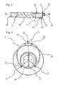
- Fig. 2 combined with Fig. 3 show that the clip means 2 is equipped with two projections 20, which are both arranged in a middle section 21 on one lateral side 22 thereof.
- Those projections 20 cooperate with one rim 13 of the spool element 1 and project the outer end face 15 in axial direction.
- the projections 20 have an abutment section 23 abutting against the radial end face 14 of the rim 13.
- the projections 20 each have furthermore a guide section 24, which radially projects the radial end face 14 towards the centre 17 of the spool element 1.
- the C-shaped clip means 2 is provided with a bore 25, from which two legs 26 of identical length and shape, project. Both legs 26 have a rectangular cross-sectional shape. A free end 27 is bent in a radial outward direction.
- the clip means 2 is centred with respect to a radial middle axis 28 of the spool element 1 by means of the projections 20 and the lateral outer sides 22 of the clip means 2 legs 26 interacting with the rims 13.
- the bore 25 is provided with a prolongation in form of a guiding tube 29 radially projecting a outer circumferential surface 30 of the clip means 2 which are both eccentric with respect to the radial middle axis 28 of the spool element 1.
- the bore 25 combined with the guiding tube 29 and the projections 20 are arranged in the middle section 21 on two different axial sides of a radially extending middle axis 28 of the spool element 1.
- the lateral outer side 22 of the clip means 2 opposed to that equipped with the projections 20 is provided with a convex projection 31 extending over the outer end face 15 of the spool element 1 in axial direction.
- the clip means 2 provides contact sections 32 cooperating with the circumferential surface 12 of the spool element 1. Those contact sections 32 adjacent to the free ends 27 of the legs 26, are contacting the circumferential surface 12 on one half of the spool element 1.
- the bore 25, i.e., the centre of the contact between the projections 20 and the rim 13 is arranged on the other half of the spool element 1.
- the angle between these three contact sections 21, 32 is indicated with a and is about 135°.
- the C-shaped clip means 2 mounted on the spool element 1 is held on the spool element 1 by the elastic force of the legs 26. Those legs 26 will be biased against the circumferential surface 12.
- the middle section 21 of the clip means 2 is provided with distance from the circumferential surface 12 of the spool element 1, there is provided a compartment 33 between the two elements 1, 2 for accommodating an optical fibre element. At the contact sections 32, such optical fibre element will be held between the free ends 27 of the legs 26 and the circumferential surface 12 and thus, a coil of optical fibre element being wound on the circumferential surface 12 is held in place on the spool element 1.
- the optical fibre element is introduced into the compartment 33 through the bore 25 and the guiding tube 29.
- the free end of an optical fibre element may be secured against the spool element 1, e.g., by introducing this free end through another bore provided in the spool element 1.
- the respective optical fibre element can be wound on the circumferential surface 12 by rotating the clip means 2 relative to the spool element 1.
- a connector plug for connecting the optical fibre to a mating optical fibre.
- Such plug element being made available at a predetermined position relative to the spool element 1.
- the clip means 2 Due to the radial tension provided at the contact sections 32, the clip means 2 will be held with sufficient friction forces against the spool element 1. Those friction forces may be adapted by altering the surfaces of the projections 20 and the radial end face 14 of the rim 13. This radial end face 14 can be rough to increase the friction forces and thereby improve the holding forces for keeping the clip means 2 in place relative to the spool element 1.
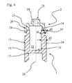
- Fig. 4 shows another embodiment of the current invention, which differs from the first embodiment in following described characteristics. Corresponding components to figures 1 to 3 are marked with same reference signs.
- Fig. 4 shows a cross-sectional view of the spool element 1 and the clip means 2.
- the spool element 1 differs to the spool element 1 of the first embodiment in that, the two rims 13 have a thick base section 34 and a thinned radial outer lip section 35, the inner surface of which extending in radial direction of the spool element 1 is in alignment with the respective inner surface of the base section 34, while the axial outer surface of the outer lip section 35 is provided inwardly with respect to the outer end face 15 of the spool element 1. While the base section 34 has a thickness d3, the thinned outer lip section 35 has a thickness d1.
- the clip means 2 is positioned in axial direction relative to the spool element 1.
- the guide section 24 has a thickness in axial direction of the spool identified as d2, such that the sum of both thicknesses d1 of the thinned outer lip section 35 and d2 of the guide section 24 is less than the thickness d3 of the base section 34 of the rim 13.
- the storing device may lie on an outer end face 15 of the spool element 1, while still allowing the clip means 2 to slide and rotate about the centre 17 of the spool element 1.
Landscapes
- Physics & Mathematics (AREA)
- General Physics & Mathematics (AREA)
- Optics & Photonics (AREA)
- Storage Of Web-Like Or Filamentary Materials (AREA)
- Light Guides In General And Applications Therefor (AREA)
Abstract
The present invention proposes a storing device for an optical fibre coil, which can be manufactured and handled easily and which comprises a spool element (1) having a circumferential surface (12) and a C-shaped clip means (2) adapted to elastically encompass said circumferential surface (12) and to slide on said circumferential surface (12).
Description
- The present invention relates to a device for storing length of optical fibre.
- In general, when connecting optical fibre to each other, a certain length of optical fibre needs to be available during the operation. However, after a respective connection has been achieved, the overlength needs to be stored. This is in particular advantageous in case of optical fibre distribution systems, in which a plurality of optical fibres are held in a common unit for connecting the optical fibres to connectors and/or storing excess optical fibres leading to the unit, which may be connected to an outgoing signal line, if required.
- Storage of optical fibres imposes specific requirements, which are brought about by the character of the optical fibres. In particular, optical fibres are likely to break in the event the fibres are bent. Thus, storing of excess optical fibre length requires careful handling of the optical fibre elements and working above a threshold bending radius. In the event the bending radius becomes too small, optical losses will be generated in the optical fibre element, which negatively effect the optical signal to be transmitted in the optical fibre element.
- Apart from that, any storing device for excess length of optical fibre cable should likewise protect the excess length, thus, stored from mechanical impact.
- In view of those requirements,
US 2007/0031101 proposes a storing device for two optical cables of a fibre optic set, which may be wound onto two separate spools for extension and retraction relative to a casing. The casing has two casing parts, which are connected to each other thereby including one of the spools having a cylindrical body. On the outer side of one of the casing parts and a cover for said casing parts, there is provided the second spool. Both of these spools are rotatable relative to the casing and the cover. After assembly work, the two spools are encapsulated within the casing and the cover. - While this storing device allows connection of the two optical fibres and storage of an overlength of optical fibre, after connecting the same with each other, this prior art storing device is complicated and thus, expensive to manufacture.
-
JP 7043537 A - An alternative proposal for a storing device is known from
US 2008/0152294 A1 . This known storing device comprises a container for an optical fibre coil including a first part for accommodating a coil having a functional fibre and a second part disposed on an outer periphery side of the first part and windingly accommodating a pigtail fibre that is optically connected to the functional optical fibre. The second part has a gap that extends over the entirety of the outer periphery and communicates with the exterior. The length of optical fibre, which can be stored in this known storing device, has to be manually fitted into the gap. This operation is troublesome and may lead to excessive bending of the fibre. Apart from that, the optical fibre can only be introduced into the container at predetermined positions on the outer circumference of the container. Thus, it is troublesome to exactly store the desired length of optical fibre within the container. Still further, the container is rather complex. - Despite the aforementioned examples of prior art storing devices, there is still need to improve the storing device. The present invention aims to provide a storing device, which is easy to manufacture and to operate when storing excess length of optical fibre cables and which can be manufactured at low costs.
- As a solution to the above object, the present invention provides a storing device as claimed in
claim 1. This storing device has a spool element having a circumferential surface, on which the optical fibre can be wound. The circumferential surface is usually projected in radial direction by ring-shaped radial rims continuously extending in the circumferential direction. Thus, there is provided a U-shaped compartment for accommodating the excess length of optical fibre cable. The storing device of the present invention furthermore comprises a C-shaped clip means, which is adapted to elastically encompass the circumferential surface. Further, the C-shaped clip means is adapted to slide on the circumferential surface of the spool. - The C-shaped clip is secured to the spool preferably by elastic forces of the C-shaped clip only. In other words, assembly of the storing device can be attained by sliding the C-shaped clip over the circumferential surface in radial direction of the spool. In view of this, any excess length can, e.g., be wound on the spool with the C-shaped clip removed from the spool. After winding of the excess length of optical fibre, the coil of optical fibre wound on the spool element can be secured in place by sliding the C-shaped clip over the circumferential surface. The C-shaped clip will press the optical fibre element against the circumferential surface in radial direction at least over certain areas in circumferential direction. Thus, the optical fibre element is held in place on the circumferential surface of the spool element. The C-shaped clip may already abut the circumferential surface adapted to receive optical fibre length in an unloaded state of the storing device, i.e. in absence of any optical fibre element. It can, however, be configured such, that it only encompasses, i.e. grips around the maximum diameter of the circumferential surface of the spool element without abutting against the same in a loaded state.
- The C-shaped clip means is preferably configured such, that free ends of two legs of the C-shaped clip means are provided distant from each other with the C-shaped clip means provided on the circumferential surface of the spool element and encompassing the same in circumferential direction. This distance of the free end of the legs provides an area, in which the optical fibre cable can be introduced into the storing device. However, the optical fibre cable does not necessarily be introduced into the storing device between the opposing ends of the two legs. The spool element can, for example, have a bore for introducing the optical fibre cable into the spool element. This bore can be provided on the side faces of the spool, i.e., in the rim or be provided projecting through the circumferential surface for winding the optical fibre element.
- As the C-shaped clip means is slidable on the circumferential surface of the spool element, winding or unwinding can be attained by rotating the clip means relative to the spool element. The legs may have any suitable configuration and cross-sectional shape in order to allow such rotational movement while providing sufficient elastic compression force, which compression force is suitable to hold the optical fibre element coiled on the spool element.
- In order to thoroughly secure the C-shaped clip means against the spool element, the distance of opposing ends of the C-shaped clip means in a non-tensioned condition, is smaller than the diameter of the spool element. This diameter is to be regarded as the diameter of the circumferential surface, on which the optical fibre element is coiled. The non-tensioned condition is the condition of the elastic C-shaped clip means prior to assembly on the spool element. With this preferred embodiment of the present invention, the opposing legs of the clip means are biased in radial outward direction when pushing the clip means over the spool element. After passing the maximum diameter of the circumferential surface of the spool element, the clip means are necessarily brought into a final position, in which the clip means encompasses the circumferential surface and is held on the spool by the elastic forces exerted by the legs of the clip means.
- According to a preferred embodiment of the present invention, the clip means abuts against the spool element at positions, which are spaced from one another by an angle α of between 100° and 160°, preferably by 120° and 140°. In this preferred embodiment, the clip means abuts against the spool element at three positions, one position thereof being arranged on one half of the spool element, while the two other positions are arranged on the other half of the spool element. Regularly, two of those contact positions provide contact between the C-shaped clip means and the circumferential surface of the spool element. The third position, which usually is provided in a middle section of the C-shaped clip means, may contact the circumferential surface of the spool element. However, in a preferred embodiment, this middle section is in contact with the rim of the spool element, which extends continuously in circumferential direction of the spool element.
- In a yet preferred embodiment of the present invention, the C-shaped clip means comprises a bore adapted to receive the optical fibre element. Preferably, this bore is radially extended by a guiding means, which projects the C-shaped clip means in radial outward direction. The axial end faces of the bore and the guide means are preferably rounded so as to prevent the optical fibre element guided through the bore and the guide means from excessive bending. The bore and the guide means have a diameter, which is larger than the outer diameter of the optical fibre element. Preferably, the ratio between the diameter of the bore and the diameter of the optical fibre element should not exceed three in order to prevent the optical fibre element stored on the circumferential surface of the spool element from unintentionally projecting through the bore in radial outward direction.
- In a preferred embodiment of the present invention, the bore is arranged between the two legs of the C-shaped clip means with the free ends being biased against the circumferential surface of the spool element at determined contact points provided on one half of the spool element with the bore being provided on the other half of the spool element.
- Further preferred embodiments of the present invention are set out in the dependent claims.
- Two embodiments of the present invention will now be more particularly described, by way of example, with reference to the accompanying drawings in which:
-
Fig. 1 is a perspective view of a first embodiment; -
Fig. 2 is a cross-sectional view along lines II-II inFig. 1 ; -
Fig. 3 is a cross-sectional view along lines III-III inFig. 2 , and -
Fig. 4 is a cross-sectional view of a second embodiment. -
Fig. 1 shows an embodiment of the inventive storing device comprising aspool element 1 and a clip means 2. - The
spool element 1 has aring core 11, which provides an outercircumferential surface 12 and which is projected radially by ring-shapedrims 13, which are continuously extending in circumferential direction and provide radial end faces 14 and outer end faces 15. On the inner side of the core 11, there are provided tworadius arms 16, which extend diametrically across acentre 17 in theinner ring core 11. -
Fig. 2 combined withFig. 3 show that the clip means 2 is equipped with twoprojections 20, which are both arranged in amiddle section 21 on onelateral side 22 thereof. Thoseprojections 20 cooperate with onerim 13 of thespool element 1 and project the outer end face 15 in axial direction. Specifically, theprojections 20 have anabutment section 23 abutting against the radial end face 14 of therim 13. Theprojections 20 each have furthermore aguide section 24, which radially projects the radial end face 14 towards thecentre 17 of thespool element 1. - The C-shaped clip means 2 is provided with a
bore 25, from which twolegs 26 of identical length and shape, project. Bothlegs 26 have a rectangular cross-sectional shape. A free end 27 is bent in a radial outward direction. The clip means 2 is centred with respect to a radialmiddle axis 28 of thespool element 1 by means of theprojections 20 and the lateralouter sides 22 of the clip means 2legs 26 interacting with therims 13. Thebore 25 is provided with a prolongation in form of a guidingtube 29 radially projecting a outercircumferential surface 30 of the clip means 2 which are both eccentric with respect to the radialmiddle axis 28 of thespool element 1. Thebore 25 combined with the guidingtube 29 and theprojections 20 are arranged in themiddle section 21 on two different axial sides of a radially extendingmiddle axis 28 of thespool element 1. The lateralouter side 22 of the clip means 2 opposed to that equipped with theprojections 20 is provided with aconvex projection 31 extending over the outer end face 15 of thespool element 1 in axial direction. - As evident from the drawing according to
Fig. 3 , the clip means 2 providescontact sections 32 cooperating with thecircumferential surface 12 of thespool element 1. Thosecontact sections 32 adjacent to the free ends 27 of thelegs 26, are contacting thecircumferential surface 12 on one half of thespool element 1. Thebore 25, i.e., the centre of the contact between theprojections 20 and therim 13 is arranged on the other half of thespool element 1. The angle between these threecontact sections - Due to this configuration, the C-shaped clip means 2 mounted on the
spool element 1 is held on thespool element 1 by the elastic force of thelegs 26. Thoselegs 26 will be biased against thecircumferential surface 12. As themiddle section 21 of the clip means 2 is provided with distance from thecircumferential surface 12 of thespool element 1, there is provided acompartment 33 between the twoelements contact sections 32, such optical fibre element will be held between the free ends 27 of thelegs 26 and thecircumferential surface 12 and thus, a coil of optical fibre element being wound on thecircumferential surface 12 is held in place on thespool element 1. - The optical fibre element is introduced into the
compartment 33 through thebore 25 and the guidingtube 29. The free end of an optical fibre element may be secured against thespool element 1, e.g., by introducing this free end through another bore provided in thespool element 1. With such a preparation, the respective optical fibre element can be wound on thecircumferential surface 12 by rotating the clip means 2 relative to thespool element 1. It may likewise be possible to provide the free end of the optical fibre cable with a connector plug for connecting the optical fibre to a mating optical fibre. Such plug element being made available at a predetermined position relative to thespool element 1. By rotating the clip means 2 around thespool element 1, the optical fibre element prepared in this way can be wound and, thus, stored on thecircumferential surface 12. - Due to the radial tension provided at the
contact sections 32, the clip means 2 will be held with sufficient friction forces against thespool element 1. Those friction forces may be adapted by altering the surfaces of theprojections 20 and the radial end face 14 of therim 13. This radial end face 14 can be rough to increase the friction forces and thereby improve the holding forces for keeping the clip means 2 in place relative to thespool element 1. -
Fig. 4 shows another embodiment of the current invention, which differs from the first embodiment in following described characteristics. Corresponding components tofigures 1 to 3 are marked with same reference signs.Fig. 4 shows a cross-sectional view of thespool element 1 and the clip means 2. Thespool element 1 differs to thespool element 1 of the first embodiment in that, the tworims 13 have athick base section 34 and a thinned radialouter lip section 35, the inner surface of which extending in radial direction of thespool element 1 is in alignment with the respective inner surface of thebase section 34, while the axial outer surface of theouter lip section 35 is provided inwardly with respect to the outer end face 15 of thespool element 1. While thebase section 34 has a thickness d3, the thinnedouter lip section 35 has a thickness d1. - As two of the
projections 20 are positioned opposite to each other with respect to the radialmiddle axis 28 of thespool element 1, with theguide sections 24 encompassing theouter lip sections 35 of opposingrims 13, the clip means 2 is positioned in axial direction relative to thespool element 1. Theguide section 24 has a thickness in axial direction of the spool identified as d2, such that the sum of both thicknesses d1 of the thinnedouter lip section 35 and d2 of theguide section 24 is less than the thickness d3 of thebase section 34 of therim 13. Thus, the storing device may lie on an outer end face 15 of thespool element 1, while still allowing the clip means 2 to slide and rotate about thecentre 17 of thespool element 1. - As evident from the drawing according to
Fig. 4 thebore 25 and the guidingtube 29 are both centred with respect to the radialmiddle axis 28 of thespool element 1. This embodiment does not provide theconvex projection 31 known from the first embodiment. -
- 1 - spool element
- 2 - clip means
- 11 - ring core
- 12 - circumferential surface
- 13 - rim
- 14 - radial end face
- 15 - outer end face
- 16 - radius arms
- 17 - centre
- 20 - projection
- 21 - middle section
- 22 - lateral side
- 23 - radial abutment section
- 24 - guide section
- 25 - bore
- 26 - legs
- 27 - free end
- 28 - radial middle axis
- 29 - guiding tube
- 30 -outer circumferential surface
- 31 - convex projection
- 32 - contact section
- 33 - compartment
- 34 - base section
- 35 - outer lip section
Claims (12)
- Storing device for an optical fibre coil comprising a spool element (1) having a circumferential surface (12) and a C-shaped clip means (2) adapted to elastically encompass said circumferential surface (12) and to slide on said circumferential surface (12).
- Storing device according to claim 1, characterized in that said spool element (1) has a diameter larger than the distance of opposing ends (27) of said C-shaped clip means (2) in a non-tensioned condition.
- Storing device according to claims 1 or 2, characterized in that said C-shaped clip means (2) abuts against said spool element (1) at positions (21, 32), which are spaced from one another by an angle (α) of between 100° and 160°, preferably by 120° and 140°.
- Storing device according to any of the preceding claims, characterized in that said C-shaped clip means (2) comprises a bore (25) adapted to receive said optical fibre element.
- Storing device according to claim 4, characterized in that said bore (25) is arranged between two legs (26) of said C-shaped clip means (2).
- Storing device according to claims 4 or 5, characterized in that said bore (25) is arranged eccentrically with respect to a radial middle axis (28) of the spool element (1).
- Storing device according to any of the preceding claims 4 to 6, characterized in that the free ends (27) of said C-shaped clip means (2) are biased against said circumferential surface (12) at a contact point (32) provided on one half of the spool element (1) with the bore (25) being provided on the other half of said spool element (1).
- Storing device according to any of the preceding claims, characterized in that said spool element (1) has rims (13) projecting said circumferential surface (12) and that said C-shaped clip means (2) is provided with projections (20) abutting against said rims (13).
- Storing device according to claim 8, characterized in that said projections (20) are arranged in the circumferential middle section (21) of the C-shaped clip means (2).
- Storing device according to claim 8 or 9, characterized in that said projections (20) are arranged on one lateral side (22) of the clip means (2).
- Storing device according to claim 10 or 11, characterized in that said projections (20) have a radial abutment section (23) cooperating with the radial end face (14) of said rim (13) and a guide section (24) radially projecting the radial end surface (14) towards a centre (17) of said spool element (1).
- Storing device according to claim 11, characterized in that said guide section (24) is provided on the outer side of said rim (13).
Priority Applications (1)
| Application Number | Priority Date | Filing Date | Title |
|---|---|---|---|
| EP10002635A EP2369386A1 (en) | 2010-03-12 | 2010-03-12 | Storing device for an optical fibre coil |
Applications Claiming Priority (1)
| Application Number | Priority Date | Filing Date | Title |
|---|---|---|---|
| EP10002635A EP2369386A1 (en) | 2010-03-12 | 2010-03-12 | Storing device for an optical fibre coil |
Publications (1)
| Publication Number | Publication Date |
|---|---|
| EP2369386A1 true EP2369386A1 (en) | 2011-09-28 |
Family
ID=42732101
Family Applications (1)
| Application Number | Title | Priority Date | Filing Date |
|---|---|---|---|
| EP10002635A Withdrawn EP2369386A1 (en) | 2010-03-12 | 2010-03-12 | Storing device for an optical fibre coil |
Country Status (1)
| Country | Link |
|---|---|
| EP (1) | EP2369386A1 (en) |
Citations (5)
| Publication number | Priority date | Publication date | Assignee | Title |
|---|---|---|---|---|
| JPH0743537A (en) | 1993-08-02 | 1995-02-14 | Furukawa Electric Co Ltd:The | Optical fiber connection module |
| US20060049294A1 (en) * | 2002-12-13 | 2006-03-09 | Fabrice Thebault | Packaging reel with optical cable winding device |
| US20070031101A1 (en) | 2005-08-08 | 2007-02-08 | Fiber Optic Protection Systems, Inc. | Fiber optic cable protective apparatus |
| US20080152294A1 (en) | 2006-10-26 | 2008-06-26 | Sumitomo Electric Industries, Ltd. | Container for accommodating optical fiber coil and optical fiber module having the container |
| DE202009009985U1 (en) * | 2009-07-21 | 2009-12-24 | Nokia Siemens Networks Gmbh & Co.Kg | Housing for fiber optic based fiber optic cables |
-
2010
- 2010-03-12 EP EP10002635A patent/EP2369386A1/en not_active Withdrawn
Patent Citations (5)
| Publication number | Priority date | Publication date | Assignee | Title |
|---|---|---|---|---|
| JPH0743537A (en) | 1993-08-02 | 1995-02-14 | Furukawa Electric Co Ltd:The | Optical fiber connection module |
| US20060049294A1 (en) * | 2002-12-13 | 2006-03-09 | Fabrice Thebault | Packaging reel with optical cable winding device |
| US20070031101A1 (en) | 2005-08-08 | 2007-02-08 | Fiber Optic Protection Systems, Inc. | Fiber optic cable protective apparatus |
| US20080152294A1 (en) | 2006-10-26 | 2008-06-26 | Sumitomo Electric Industries, Ltd. | Container for accommodating optical fiber coil and optical fiber module having the container |
| DE202009009985U1 (en) * | 2009-07-21 | 2009-12-24 | Nokia Siemens Networks Gmbh & Co.Kg | Housing for fiber optic based fiber optic cables |
Similar Documents
| Publication | Publication Date | Title |
|---|---|---|
| US8474742B2 (en) | Spool for telecommunications cable and method | |
| EP3193197B1 (en) | Optical connector | |
| CA2760117C (en) | Apparatus and method for storing and dispensing a pressure hose | |
| US7680386B2 (en) | Retractable module for patch cords | |
| US10228527B2 (en) | Gimbal transmission cable management | |
| US9126802B2 (en) | Payout spool with automatic cable disconnect/reconnect | |
| US9594217B2 (en) | Fiber optic splicing assembly | |
| US20070036506A1 (en) | Fiber Optic Rotary Coupling and Devices | |
| KR960013960B1 (en) | Transmission apparatus between rotary body and fixed body | |
| US20120205477A1 (en) | Spool for telecommunications cable and method | |
| US20130287359A1 (en) | Cable payout cassette with single layer cable storage area | |
| JP2013176836A5 (en) | ||
| JP2013176836A (en) | Line guide system for receiving and guiding supply line, and machine tool | |
| TW201723550A (en) | Plug with built-in connector | |
| EP3707091B1 (en) | Reel device | |
| US11029473B2 (en) | Fiber optic connector | |
| US9739954B1 (en) | Strain relief device for a fiber optic connector | |
| CA2838548C (en) | Device for unwinding and winding up one or more lines | |
| KR20230029998A (en) | swivel connector device | |
| US9049851B2 (en) | Line guide | |
| US10464778B2 (en) | Cord reel device and electronic device | |
| CN108152905B (en) | Modularized miniaturized tail fiber automatic telescopic storage device | |
| CN112103871A (en) | Pipe sleeve | |
| CN202512283U (en) | Device for containing optical fiber jumper | |
| CN110048363B (en) | Anti-kink device for cables |
Legal Events
| Date | Code | Title | Description |
|---|---|---|---|
| PUAI | Public reference made under article 153(3) epc to a published international application that has entered the european phase |
Free format text: ORIGINAL CODE: 0009012 |
|
| AK | Designated contracting states |
Kind code of ref document: A1 Designated state(s): AT BE BG CH CY CZ DE DK EE ES FI FR GB GR HR HU IE IS IT LI LT LU LV MC MK MT NL NO PL PT RO SE SI SK SM TR |
|
| AX | Request for extension of the european patent |
Extension state: AL BA ME RS |
|
| STAA | Information on the status of an ep patent application or granted ep patent |
Free format text: STATUS: THE APPLICATION IS DEEMED TO BE WITHDRAWN |
|
| 18D | Application deemed to be withdrawn |
Effective date: 20120329 |