EP2369282B1 - An apparatus and a method for a natural draft air cooled condenser cooling tower - Google Patents
An apparatus and a method for a natural draft air cooled condenser cooling tower Download PDFInfo
- Publication number
- EP2369282B1 EP2369282B1 EP11158989.1A EP11158989A EP2369282B1 EP 2369282 B1 EP2369282 B1 EP 2369282B1 EP 11158989 A EP11158989 A EP 11158989A EP 2369282 B1 EP2369282 B1 EP 2369282B1
- Authority
- EP
- European Patent Office
- Prior art keywords
- duct
- fluid
- manifold
- radial
- air
- Prior art date
- Legal status (The legal status is an assumption and is not a legal conclusion. Google has not performed a legal analysis and makes no representation as to the accuracy of the status listed.)
- Active
Links
Images








Classifications
-
- F—MECHANICAL ENGINEERING; LIGHTING; HEATING; WEAPONS; BLASTING
- F28—HEAT EXCHANGE IN GENERAL
- F28B—STEAM OR VAPOUR CONDENSERS
- F28B1/00—Condensers in which the steam or vapour is separate from the cooling medium by walls, e.g. surface condenser
- F28B1/06—Condensers in which the steam or vapour is separate from the cooling medium by walls, e.g. surface condenser using air or other gas as the cooling medium
-
- F—MECHANICAL ENGINEERING; LIGHTING; HEATING; WEAPONS; BLASTING
- F28—HEAT EXCHANGE IN GENERAL
- F28D—HEAT-EXCHANGE APPARATUS, NOT PROVIDED FOR IN ANOTHER SUBCLASS, IN WHICH THE HEAT-EXCHANGE MEDIA DO NOT COME INTO DIRECT CONTACT
- F28D1/00—Heat-exchange apparatus having stationary conduit assemblies for one heat-exchange medium only, the media being in contact with different sides of the conduit wall, in which the other heat-exchange medium is a large body of fluid, e.g. domestic or motor car radiators
- F28D1/02—Heat-exchange apparatus having stationary conduit assemblies for one heat-exchange medium only, the media being in contact with different sides of the conduit wall, in which the other heat-exchange medium is a large body of fluid, e.g. domestic or motor car radiators with heat-exchange conduits immersed in the body of fluid
- F28D1/04—Heat-exchange apparatus having stationary conduit assemblies for one heat-exchange medium only, the media being in contact with different sides of the conduit wall, in which the other heat-exchange medium is a large body of fluid, e.g. domestic or motor car radiators with heat-exchange conduits immersed in the body of fluid with tubular conduits
Definitions
- the present invention relates to a natural draft cooling tower that employs an air cooled condenser.
- the aforementioned cooling tower operates by natural draft and achieves the exchange of heat between two fluids such as atmospheric air, ordinarily, and another fluid which is usually steam.
- the aforementioned cooling tower operates by natural draft which utilizes buoyancy via a tall chimney. Warm, air naturally rises due to the density differential to the cooler outside ambient air. Warm air is indeed obviously less dense than colder ambient air at the same pressure.
- Cooling towers are heat exchangers of a type widely used to emanate low grade heat to the atmosphere and are typically utilized in electricity generation, air conditioning installations and the like.
- airflow is induced via hollow chimney-like tower by the density difference between cool air entering the bottom of the tower and warm air leaving the top. This difference is due to heat transfer from the fluid being cooled, which is passed through the interior of the tower.
- Cooling towers may be wet or dry.
- Dry cooling towers can be either "Direct Dry,” in which steam is directly condensed by air passing over a heat exchange medium containing the steam or an "Indirect Dry” type natural draft cooling towers, in which the steam first passes through a surface condenser cooled by a fluid and this warmed fluid is sent to a cooling tower heat exchanger where the fluid remains isolated from the air, similar to an automobile radiator. Dry cooling has the advantage of no evaporative water losses. Both types of dry cooling towers dissipate heat by conduction and convection and both types are presently in use. Wet cooling towers provide for direct air contact to a fluid being cooled. Wet cooling towers benefit from the latent heat of vaporization which provides for very efficient heat transfer but at the expense of evaporating a small percentage of the circulating fluid.
- cooling towers can be further classified as either cross-flow or counter-flow.
- cross-flow cooling tower the air moves horizontally through the fill or packing as the liquid to be cooled moves downward.
- counter-flow cooling tower air travels upward through the fill or packing, opposite to the downward motion of the liquid to be cooled.
- the condenser To accomplish the cooling required the condenser requires a large surface area to dissipate the thermal energy in the gas or steam and presents several problems to the design engineer. It is difficult to efficiently and effectively direct the steam to all the inner surface areas of the condenser because of nonuniformity in the delivery of the steam due to system ducting pressure losses and velocity distribution. Therefore, uniform steam distribution is desirable in air cooled condensers and is critical for optimum performance. Therefore it would be desirous to have a condenser with a strategic layout of ducting and condenser surfaces that would ensure an even distribution of steam throughout the condenser, while permitting a maximum of cooling airflow throughout and across the condenser surfaces.
- a typical type of expansion joint for pipe systems is a bellow which can be manufactured from metal (most commonly stainless steel).
- a bellow is made up of a series of one or more convolutions, with the shape of the convolution designed to withstand the internal pressures of the pipe, but flexible enough to accept the axial, lateral, and/or angular deflections.
- branching of the steam ducting is required to distribute the steam to the various coil sections of the condenser. The very nature of branching breaks the steam flow into different directions which necessarily introduces thermal expansion in different directions.
- These expansion accommodating devices are expensive. Therefore it would be additionally desirous to have a condenser arrangement in which the thermal expansion and contraction is simply and inexpensively managed.
- the natural draft cooling tower typically has a hollow, open-topped shell of reinforced concrete with an upright axis of symmetry and circular cross-section.
- the thin walled shell structure usually comprises a necked, hyperbolic shape when seen in meridian cross-section or the shell may have a cylindrical or conical shape. Openings at the base of the tower structure enable ingress of ambient air to facilitate heat exchange from the fluid to the air.
- Forced draft cooling towers are also known, in which the airflow is produced by fans. These devices usually do not incorporate a natural draft shell because the fans replace the chimney effect of the natural draft cooling towers . However, forced draft fans may be incorporated in a natural draft design to supplement airflow where the density difference described above is not sufficient to produce the desired airflow.
- cooling tower performance i.e. the ability to extract an increased quantity of waste heat in a given surface
- cost-effective methods of improvement are desired.
- the present invention addresses this desire. Equivalent considerations can apply in other industries where large natural draft cooling towers are used.
- large natural draft cooling towers are high-capital-cost, long-life fixed installations, and it is desirable that improvements be obtainable without major modifications, particularly to the main tower structure.
- the method and apparatus of the present invention are applicable to the improvement of existing natural draft cooling towers, as well as to new cooling towers.
- Airflow dampers are known to be used is series with heat exchangers. The dampers may be throttled to restrict the airflow. However, even in the wide open position a pressure loss through the damper occurs. This pressure loss reduces the total airflow and thus the cooling capacity of the tower.
- a natural draft cooling tower may extract too much heat energy out of the heated liquid or have the liquid to be cooled freeze up.
- a dry cooling tower may extract too much thermal energy away from the heated liquid condensate, which would require extra heating energy from a boiler or heat source to reheat the liquid back to its optimal temperature, thus lowering the system's efficiency.
- a wet tower on the other hand is susceptible to ice formation in cold weather. In particular ice may form and build up in the fill and cause structural damage to the fill and /or the supporting structure.
- DE 19 46 915 A1 discloses an air-cooled condenser for distillation wherein the overhead vapours from a distillation column pass through a riser pipe and tubes into outwardly-finned tubes assembled in vertical planes around a chamber above the column, the finned tubes being disposed symmetrically in respect of the vertical axis of the column and being surrounded by a sheathing which is closed at the top but open to the atmosphere at the base so that air is drawn in by a fan and flows between the finned tubes thereby causing condensation of the vapours therein.
- the condensate collects in chambers and a pipe from which some of the condensate is refluxed to the column and the remainder is withdrawn as product.
- EP 0 553 435 A2 discloses a natural draft cooling tower having a plurality of roof-shaped heat exchange elements for the condensation of the turbine steam of a power station.
- the heat exchange elements are supplied with the steam to be condensed via a common, centrally arranged steam feed line and distribution lines which branch off radially therefrom being connected in part in a condensing fashion and in part in a partially condensing fashion, wherein the heat exchange elements connected in a partially condensing fashion are arranged on the steam side downstream of the heat exchange elements connected in a condensing fashion.
- the heat exchange elements are distributed over a plurality of identical sectors which in each case have complete lines for steam distribution as well as drainage of inert gas and condensate. Further, the heat exchange elements connected in a condensing fashion are arranged with their longitudinal axis on a support structure in each case like a secant relative to the central steam feed line.
- DE 19 60 619 A1 discloses a natural draught cooling tower for vapours or liquids with circumferential bottom inlet and open top, wherein the liquid to be cooled passes through closed, smooth or ribbed tubes.
- the heat exchange elements or their constituents are arranged at a height increasing towards the tower centre, in general correspondence to the increase in upward air flow rate towards the centre. Specifically, the elements are arranged as a flat pyramid or cone frustrated pyramid or frustrated cone.
- Embodiments of the present invention advantageously provide for a natural draft cooling tower of claim 1 and a method for cooling an industrial fluid, usually steam, of claim 9. Preferred embodiments and method variants are disclosed in the respective dependent claims.
- FIG. 1 is a schematic diagram of the steam/water circuit 1 of a greatly-simplified electric power generating installation.
- a boiler 2 produces steam which travels via a duct 3 to a steam turbine 4 which drives a generator 5.
- the boiler 2 may fired with fossil fuel such as coal or natural gas to provide heat or the heat source may be a nuclear reactor (not shown).
- Wet steam exiting the steam turbine 4 is condensed in a heat exchanger 6 and exits as water, which is recirculated as feed water to the boiler 2 via a feed water pump 7.
- a separate cooling water supply is provided to heat exchanger 6 via a duct 8 and exits at an elevated temperature via a duct 9, being pumped by cooling water pumps 10.
- a large supply of water is available from a lake, river or artificial cooling pond for use as cooling water.
- cooling water may be directly recirculated as shown in FIG. 1 , passing through a cooling tower 11 to lower its temperature before returning to the heat exchanger 6 via duct 8. This arrangement avoids the need for a large natural supply of cooling water.
- circuit 1 is for illustrative purposes only. In a practical power generating facility, (not shown) there may be additional components, such as economisers, superheaters, and (usually) multiple boilers and turbines and ducting to accommodate them.
- Wet or evaporative cooling towers are heat exchangers of the type in which a liquid as shown in FIG. 1 is cooling water is passed into a space through which a gas atmospheric air is flowing and in that space is cooled by direct contact with the cooler air and by partial evaporation. To give sufficiently long liquid residence times and gas/liquid interface areas. The liquid is often sprayed into the space, falling downward or being splashed onto a large-surface-area fixed structure (known for example as "packing") at the base of the tower, finally collecting in a basin below the packing.
- packing large-surface-area fixed structure
- the flow of gas is normally produced by fans, typically integral with the cooling tower itself.
- natural draft is often relied on to provide the airflow.
- FIG. 2 illustrates a simple schematic of an embodiment of the present invention wherein output of a steam turbine is directly coupled to an air cooled condenser.
- the boiler 2 heats a fluid, for example water until it becomes a gas (steam).
- the steam leaves the boiler 2 via a steam duct 3 and enters the steam turbine 4, which is a mechanical device that extracts thermal energy from pressurized steam, and converts it into rotary motion.
- This rotary motion for example, may turn a generator 5 to produce electricity.
- the steam turbine is a condensing turbine.
- This type of steam turbine exhausts steam in a partially condensed state, typically of a quality near 90%, at a pressure well below atmospheric to an air cooled condenser tower 14 via duct 12.
- the air cooled condenser tower 14 further extracts thermal energy away from the steam producing a liquid with a temperature just below boiling which is collected and pumped back to the boiler 2 via pump 16 through water return duct 18.
- the steam may be generated in any of a numerous ways, for example, a coal fired boiler or a nuclear reactor.
- the waste steam egresses the turbine 32, it enters a first end of horizontal duct 34.
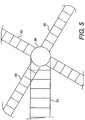
- the other end of the horizontal duct 34 is affixed to a central riser duct 36 which is located in the middle of the tower and terminates into a radial manifold 38.
- Four radial ducts 40 emanate from the radial manifold 38.
- Each radial duct is connected to a terminal duct as shown as a Y-duct 42 in FIG. 6A .
- the other sides of the Y-duct 42 are connected to the peripheral manifold 46, which is continuous about the perimeter of the tower.
- the peripheral manifold 46 is connected to the finned tube bundles 48 via a bundle duct 50.
- the system of bundles produces a circular pattern, producing the annular ring 52.
- the radial ducts can be any number. For example, there may be six or eight radial ducts emanating from the central riser duct 36 to the peripheral manifold in additional embodiments.
- FIG. 6B illustrates an alternative embodiment for connecting the radial duct 40 to the peripheral manifold 46 which employs an eased tee duct 43.
- FIG. 3 illustrates a series of columns 53 supporting shell 62.
- the ducting system hangs from the bottom of the shell and is not supported from underneath.
- FIG. 6A is a close in view of FIG. 3 .
- the radial arm ducts 40 are hanging from the bottom of tower shell 62.
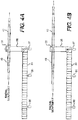
- FIGs. 4A and 4B they depict duct supports 35 to support the horizontal duct 34.
- the ducting is rigidly fixed to the support in the center of the tower and is designated 37.
- the coil tubes, ducting, and piping material are all carbon steel, thus providing an economic alternative to the more expensive material.
- An additional advantage of the above arrangement is that it allows an engineer to design an easy and inexpensive cleaning system that can be hung on a rail located on the perimeter of the cooling annular ring and above the bundles owing to the fact the tube bundles are arranged in a circumferentially oriented outward face as opposed to a pleated or zigzag arrangement.
- a cooling structure 56 comprises a base section 54 with its annular ring section 52, an angular roof section 60 and a chimney section 62.
- the base section's 54 annular ring section 52 is made up from a plurality of finned tube bundles 48 placed in a circular arrangement continuous about the perimeter as shown in FIG. 3 .
- the angular roof section 60 is essentially a warm air director between the finned tube bundles 48 and chimney section 62 and may be steel cladding or any other cooling structure building material.
- the bottom of the base stratum section 54 is at ground level and has air inlet with an airflow regulator installed.
- the airflow regulator is shown as louvers 55, which translate between an open and closed position to control airflow through the cooling structure 56.
- the louvers discussed throughout the present application can be replaced with any air flow regulation device.
- the louvers can be replaced with roll up doors, hinged doors, sliding doors or any variable structure to limit airflow through an opening.
- An optional access door 59 is also shown.
- the chimney section depicted is cylindrical; however, it can be any shape that allows for air efficient traversal through the chimney section.
- the chimney section can be in the shape of a hyperboloid, which is the shape most people associate with nuclear power generation stations.
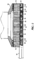
- FIG. 8 is an additional side view of the present invention which better illustrates the base stratum section 54 and the annular ring section 52.
- FIG. 9 is a side view of a slice of the finned tube bundles 48.
- the finned tube bundles 48 are attached to the peripheral manifold 46 via the bundle duct 50.
- a steam box 51 may be located on top of the finned tube bundle 48 to facilitate movement of the steam.
- a steam box in this particular embodiment may distribute the exhaust steam across the top of the set of finned tube bundles 48 to aid in the condensing of the steam.
- a measurement AA represents height of the finned tube bundle's 48 and is also illustrated on FIG 7 .
- FIG. 9 also depicts the radial and angular movement of the present system grossly exaggerated for illustrative clarity.
- FIG. 9 Also shown in FIG. 9 is a slice of the base stratum section 54 depicting where the louvers 55 could be positioned in one embodiment of the present invention.
- the louvers 55 are positioned below the finned tube bundles 48 to provide a second air path and enable air to by-pass the bundles in order to control the cooling capacity of the system.
- the louvers 55 are installed vertically and create "windows" in the vertical sealing cladding 57 located below the bundles. When the louvers are closed, the cooling capacity of the tower is maximized and all the cooling air is flowing through the bundles and the draft is at its maximum. When the louvers are in the open position, the capacity of the dry cooling tower is reduced due to two effects. The first effect is due to the reduction of cooling air flowing through the finned tube bundles.
- the second is due to the reduction of the total airflow related to the reduction of draft (chimney effect) in the tower section due to the lower temperature inside the tower created by the mixing of hot air generated by the heat of the air going through the bundles along with the cold air passing through the louvers. This is turn allows the user to control the rate and the capacity of the dry cooling tower, therefore the user can control the steam turbine back pressure.
- the louvers provide an inexpensive control system.
- the louvers are less costly than isolating valves which have to be installed on the steam ducting to neutralize the exchange surface by segments or partitions.
- the present invention needs a relatively low amount of louvers, approximately 50% of the face area of the bundles need to be covered with louvers to be effective.
- the actuators of the louvers are located on ground level enabling an easy maintenance.
- the air bypass could be located above the tube bundles and have similar air flow regulating characteristics.
- FIGs. 11A and 12A each illustrates louvers functionality in an alternative embodiment for a counter flow natural draft cooling tower.
- FIG. 11A illustrates an airflow inlet with a set of air bypass louvers 66a in a closed position and the airflow through the heat exchanger 76 is then maximized.
- the heat exchanger 76 is often made up of evaporative cooling fill in a wet tower configuration.
- the ambient air 70 enters at the base of the tower 65 through the airflow inlet with and all the of the ambient air 70 passes through the heat exchanger 76.
- the heat exchange 76 can be any type of heated fluid distribution system in which thermal energy is removed from the heated liquid.
- the heated air 72 rises due to convection. Convection above a hot surface occurs because hot air expands, becomes less dense, and rises as described in the Ideal Gas Law.
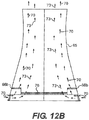
- the airflow inlet's set of air bypass louvers 66a ( FIG. 11A )can be replaced with an internal airflow bypass louvers 66b, which is located inside the tower 65.
- the first airflow inlet's bypass louvers 66a and the internal airflow bypass louvers 66b are generally louvers which translate between an open and closed position.
- the louvers for all embodiments can be mounted immediately inside the cooling tower support structure, flush to cooling tower heat exchanger or immediately outside the cooling tower heat exchanger.
- the louvers can be exchanged for door type inlet control.
- the airflow inlet's set of air bypass louvers 66a or 66b is open and air through the heat exchanger 76 is reduced.
- Ambient air 70 enters at the base of the tower 65 and the ambient air 70 is passed through the heat exchanger 76 and becomes heated air 73. Additionally, ambient air 70 enters the tower 65 above the heat exchanger 76 and mixes somewhat with the heated air 73 and exits out the top of the tower 65 and thus, the amount of air flowing through the tower is reduced.
- the first air bypass louvers 66a (or 66b) are open and air through the heat exchanger 76 is reduced.
- Ambient air 70 enters at the base of the tower 65 and the ambient air 70 is passed through the heat exchanger 76 and becomes heated air 73. Additionally, ambient air 70 enters the tower 65 above the heat exchanger 76 and mixes somewhat with the heated air 73 and exits out the top of the tower 65 and thus, the amount of airflowing through the tower is reduced.
- FIGs. 13 and 14 each illustrates louvers functionality in an alternative embodiment for a natural draft cooling tower, wherein heat exchanger 74, located outside of the tower, may be used.
- FIG. 13 illustrates the first air bypass louvers 78a is closed and air through the heat exchanger 74 is maximized.
- the ambient air 70 passes through the heat exchanger 74 into the tower.
- the heated air 72 rises and leaves out the top of the tower 65.
- the first air bypass louvers 78a can be replaced for a second air bypass louvers 78b, which is located between the tower 65 and the heat exchanger 74.
- the first air bypass 78a is open and air through the heat exchanger 74 is reduced.
- Ambient air 70 enters at the base of the tower 65 and the ambient air 70 is passed through the heat exchanger 74 and becomes heated air 72.
- the second air bypass louvers 78b ambient air 70 enters the tower 65 beyond the heat exchanger 74 and mixes with the heated air 72 and exits out the top of the tower 65 and thus the amount of air flowing through the tower is reduced.
- louvers as described in the aforementioned description and figures may be replaced by other means to regulate air flow such as but not limited to roll up doors, hinged doors, sliding doors, or butterfly valves.
Landscapes
- Engineering & Computer Science (AREA)
- Mechanical Engineering (AREA)
- General Engineering & Computer Science (AREA)
- Physics & Mathematics (AREA)
- Thermal Sciences (AREA)
- Heat-Exchange Devices With Radiators And Conduit Assemblies (AREA)
Description
- The present invention relates to a natural draft cooling tower that employs an air cooled condenser. The aforementioned cooling tower operates by natural draft and achieves the exchange of heat between two fluids such as atmospheric air, ordinarily, and another fluid which is usually steam. The aforementioned cooling tower operates by natural draft which utilizes buoyancy via a tall chimney. Warm, air naturally rises due to the density differential to the cooler outside ambient air. Warm air is indeed obviously less dense than colder ambient air at the same pressure.
- Cooling towers are heat exchangers of a type widely used to emanate low grade heat to the atmosphere and are typically utilized in electricity generation, air conditioning installations and the like. In a natural draft cooling tower for the aforementioned applications, airflow is induced via hollow chimney-like tower by the density difference between cool air entering the bottom of the tower and warm air leaving the top. This difference is due to heat transfer from the fluid being cooled, which is passed through the interior of the tower. Cooling towers may be wet or dry. Dry cooling towers can be either "Direct Dry," in which steam is directly condensed by air passing over a heat exchange medium containing the steam or an "Indirect Dry" type natural draft cooling towers, in which the steam first passes through a surface condenser cooled by a fluid and this warmed fluid is sent to a cooling tower heat exchanger where the fluid remains isolated from the air, similar to an automobile radiator. Dry cooling has the advantage of no evaporative water losses. Both types of dry cooling towers dissipate heat by conduction and convection and both types are presently in use. Wet cooling towers provide for direct air contact to a fluid being cooled. Wet cooling towers benefit from the latent heat of vaporization which provides for very efficient heat transfer but at the expense of evaporating a small percentage of the circulating fluid.
- In addition to types of cooling tower designs described above, cooling towers can be further classified as either cross-flow or counter-flow. Typically in a cross-flow cooling tower, the air moves horizontally through the fill or packing as the liquid to be cooled moves downward. Conversely, in a counter-flow cooling tower air travels upward through the fill or packing, opposite to the downward motion of the liquid to be cooled.
- In a direct dry cooling tower, the turbine steam exhaust is condensed directly in an air-cooled condenser. Approximately five to ten times the air required for mechanical draft evaporative towers is necessary for dry cooling towers. This type of cooling is usually used when little or no water supply is available. This type of system consumes very little water and emits no water vapor plume.
- To accomplish the cooling required the condenser requires a large surface area to dissipate the thermal energy in the gas or steam and presents several problems to the design engineer. It is difficult to efficiently and effectively direct the steam to all the inner surface areas of the condenser because of nonuniformity in the delivery of the steam due to system ducting pressure losses and velocity distribution. Therefore, uniform steam distribution is desirable in air cooled condensers and is critical for optimum performance. Therefore it would be desirous to have a condenser with a strategic layout of ducting and condenser surfaces that would ensure an even distribution of steam throughout the condenser, while permitting a maximum of cooling airflow throughout and across the condenser surfaces.
- Another problem with the current air cooled condensers is the expansion and contraction of the ducts and cooling surfaces caused by the temperature differentials. Pipe expansion joints may be employed at critical areas to compensate for the thermal movement. A typical type of expansion joint for pipe systems is a bellow which can be manufactured from metal (most commonly stainless steel). A bellow is made up of a series of one or more convolutions, with the shape of the convolution designed to withstand the internal pressures of the pipe, but flexible enough to accept the axial, lateral, and/or angular deflections. In all but the smallest of applications, branching of the steam ducting is required to distribute the steam to the various coil sections of the condenser. The very nature of branching breaks the steam flow into different directions which necessarily introduces thermal expansion in different directions. These expansion accommodating devices are expensive. Therefore it would be additionally desirous to have a condenser arrangement in which the thermal expansion and contraction is simply and inexpensively managed.
- The natural draft cooling tower typically has a hollow, open-topped shell of reinforced concrete with an upright axis of symmetry and circular cross-section. The thin walled shell structure usually comprises a necked, hyperbolic shape when seen in meridian cross-section or the shell may have a cylindrical or conical shape. Openings at the base of the tower structure enable ingress of ambient air to facilitate heat exchange from the fluid to the air. Forced draft cooling towers are also known, in which the airflow is produced by fans. These devices usually do not incorporate a natural draft shell because the fans replace the chimney effect of the natural draft cooling towers . However, forced draft fans may be incorporated in a natural draft design to supplement airflow where the density difference described above is not sufficient to produce the desired airflow.
- It is known that improving cooling tower performance (i.e. the ability to extract an increased quantity of waste heat in a given surface) can lead to improved overall efficiency of a steam plant's conversion of heat to electric power and/or to increases in power output in particular conditions. Cost-effective methods of improvement are desired. The present invention addresses this desire. Equivalent considerations can apply in other industries where large natural draft cooling towers are used.
- Additionally, large natural draft cooling towers are high-capital-cost, long-life fixed installations, and it is desirable that improvements be obtainable without major modifications, particularly to the main tower structure. The method and apparatus of the present invention are applicable to the improvement of existing natural draft cooling towers, as well as to new cooling towers.
- In cooler weather the return temperature of a fluid from the cooling tower and/or freezing a fluid in the heat exchanger is a major concern. When the airflow has the capacity to exchange more heat than desired the airflow must be reduced. Airflow dampers are known to be used is series with heat exchangers. The dampers may be throttled to restrict the airflow. However, even in the wide open position a pressure loss through the damper occurs. This pressure loss reduces the total airflow and thus the cooling capacity of the tower.
- Additionally, due to temperature and humidity extremes, a natural draft cooling tower may extract too much heat energy out of the heated liquid or have the liquid to be cooled freeze up. For example, a dry cooling tower may extract too much thermal energy away from the heated liquid condensate, which would require extra heating energy from a boiler or heat source to reheat the liquid back to its optimal temperature, thus lowering the system's efficiency. A wet tower on the other hand is susceptible to ice formation in cold weather. In particular ice may form and build up in the fill and cause structural damage to the fill and /or the supporting structure.
-
DE 19 46 915 A1 discloses an air-cooled condenser for distillation wherein the overhead vapours from a distillation column pass through a riser pipe and tubes into outwardly-finned tubes assembled in vertical planes around a chamber above the column, the finned tubes being disposed symmetrically in respect of the vertical axis of the column and being surrounded by a sheathing which is closed at the top but open to the atmosphere at the base so that air is drawn in by a fan and flows between the finned tubes thereby causing condensation of the vapours therein. The condensate collects in chambers and a pipe from which some of the condensate is refluxed to the column and the remainder is withdrawn as product. -
EP 0 553 435 A2 discloses a natural draft cooling tower having a plurality of roof-shaped heat exchange elements for the condensation of the turbine steam of a power station. The heat exchange elements are supplied with the steam to be condensed via a common, centrally arranged steam feed line and distribution lines which branch off radially therefrom being connected in part in a condensing fashion and in part in a partially condensing fashion, wherein the heat exchange elements connected in a partially condensing fashion are arranged on the steam side downstream of the heat exchange elements connected in a condensing fashion. The heat exchange elements are distributed over a plurality of identical sectors which in each case have complete lines for steam distribution as well as drainage of inert gas and condensate. Further, the heat exchange elements connected in a condensing fashion are arranged with their longitudinal axis on a support structure in each case like a secant relative to the central steam feed line. -
DE 19 60 619 A1 discloses a natural draught cooling tower for vapours or liquids with circumferential bottom inlet and open top, wherein the liquid to be cooled passes through closed, smooth or ribbed tubes. The heat exchange elements or their constituents are arranged at a height increasing towards the tower centre, in general correspondence to the increase in upward air flow rate towards the centre. Specifically, the elements are arranged as a flat pyramid or cone frustrated pyramid or frustrated cone. - Therefore it would be desirous to have an economical, efficient natural draft cooling tower in which the cooling airflow could also be controlled, while keeping the effects of thermal expansion and contraction of the condenser and ducting at a minimum, thus simplifying and reducing the cost maintenance.
- Embodiments of the present invention advantageously provide for a natural draft cooling tower of
claim 1 and a method for cooling an industrial fluid, usually steam, ofclaim 9. Preferred embodiments and method variants are disclosed in the respective dependent claims. - As such, those skilled in the art will appreciate that the conception upon which this disclosure is based may readily be utilized as a basis for the designing of other structures, methods and systems for carrying out the several purposes of the present invention. It is important, therefore, that the claims be regarded as including such equivalent constructions insofar as they do not depart from the scope of the present invention.
- The above-mentioned and other features and advantages of this disclosure, and the manner of attaining them, will become more apparent and the disclosure itself will be better understood by reference to the following description of various embodiments of the disclosure taken in conjunction with the accompanying figures.
-
FIG. 1 is a schematic steam/water circuit diagram of a simplified electric power generating installation in which an embodiment of the present invention that may be used. -
FIG. 2 illustrates a simple schematic illustration of an embodiment of the invention in which the output of a steam turbine is directly coupled to the condenser tower. -
FIG. 3 is a plan view of an embodiment the present invention illustrating a steam duct connecting radial ducting arms and bundles. -
FIGs. 4A and 4B are a side view of an embodiment illustrating the ducting orientation of an embodiment of the present invention and an exaggerated depiction of the radial movement of the present system. -
FIG. 5 illustrates the radial ducting arm manifold in accordance with an embodiment of the present invention. -
FIG. 6A illustrates the bifurcated ducting and a portion of the cooling annular ring section in accordance with an embodiment of the present invention and also illustrates the radial movement of the system. -
FIG. 6B illustrates an alternative arrangement for connecting the radial arm to the cooling annular ring section. -
FIG. 7 illustrates the cooling structure comprising a base stratum section, a cooling annular ring section, an angular roof section and a chimney section in accordance with an embodiment of the present invention. -
FIG. 8 is a side view orientation of the stratum section and the cooling annular ring of the present invention. -
FIG. 9 illustrates a single set of the finned tube bundles attachment to the peripheral manifold to a steam box located in accordance with an embodiment of the present invention and also illustrates the radial and angular movements of the system grossly exaggerated. -
FIG. 10 illustrates the lower section of the finned tube bundle and the collector in accordance with an embodiment of the present invention. -
FIG. 11A illustrates a cooling tower in which an air inlet bypass is closed and air through the heat exchanger is maximized in accordance with an embodiment of the present invention. -
FIG. 11B illustrates a cooling tower in which an air inlet bypass located inside a structure is closed and air through the heat exchanger is maximized in accordance with an embodiment of the present invention. -
FIG. 12A illustrates a cooling tower in which an air inlet is open and air through the heat exchanger is reduced in accordance with an embodiment of the present invention. -
FIG. 12B illustrates a cooling tower in which an air inlet bypass located inside a structure is open and air through the heat exchanger is reduced in accordance with an embodiment of the present invention. -
FIG. 13 illustrates a cooling tower in which the air bypass is closed and air through the heat exchanger is maximized, wherein the heat exchanger is located outside the tower shell structure, in accordance with an embodiment of the present invention. -
FIG. 14 illustrates a cooling tower in which the air bypass is open and air through the heat exchanger is reduced, wherein the heat exchanger is located outside the tower, in accordance with an embodiment of the present invention. - In the following detailed description, reference is made to the accompanying drawings, which form a part hereof and show by way of illustration specific embodiments in which the invention may be practiced. These embodiments are described in sufficient detail to enable those skilled in the art to practice them, and it is to be understood that other embodiments may be utilized, and that structural, logical, processing, and electrical changes may be made. It should be appreciated that any list of materials or arrangements of elements is for example purposes only and is by no means intended to be exhaustive. The progression of processing steps described is an example; however, the sequence of steps is not limited to that set forth herein and may be changed as is known in the art, with the exception of steps necessarily occurring in a certain order.
-
FIG. 1 is a schematic diagram of the steam/water circuit 1 of a greatly-simplified electric power generating installation. Aboiler 2 produces steam which travels via aduct 3 to asteam turbine 4 which drives agenerator 5. Theboiler 2 may fired with fossil fuel such as coal or natural gas to provide heat or the heat source may be a nuclear reactor (not shown). Wet steam exiting thesteam turbine 4 is condensed in aheat exchanger 6 and exits as water, which is recirculated as feed water to theboiler 2 via a feed water pump 7. - A separate cooling water supply is provided to
heat exchanger 6 via aduct 8 and exits at an elevated temperature via aduct 9, being pumped by cooling water pumps 10. In some installations, a large supply of water is available from a lake, river or artificial cooling pond for use as cooling water. However, in cases where supply is not available, cooling water may be directly recirculated as shown inFIG. 1 , passing through acooling tower 11 to lower its temperature before returning to theheat exchanger 6 viaduct 8. This arrangement avoids the need for a large natural supply of cooling water. It is to be understood thatcircuit 1 is for illustrative purposes only. In a practical power generating facility, (not shown) there may be additional components, such as economisers, superheaters, and (usually) multiple boilers and turbines and ducting to accommodate them. - Wet or evaporative cooling towers are heat exchangers of the type in which a liquid as shown in
FIG. 1 is cooling water is passed into a space through which a gas atmospheric air is flowing and in that space is cooled by direct contact with the cooler air and by partial evaporation. To give sufficiently long liquid residence times and gas/liquid interface areas. The liquid is often sprayed into the space, falling downward or being splashed onto a large-surface-area fixed structure (known for example as "packing") at the base of the tower, finally collecting in a basin below the packing. In small cooling towers of the sizes used in air conditioning and similar applications, the flow of gas is normally produced by fans, typically integral with the cooling tower itself. However, in the largest cooling towers, typical of electric power generation applications, natural draft is often relied on to provide the airflow. -
FIG. 2 illustrates a simple schematic of an embodiment of the present invention wherein output of a steam turbine is directly coupled to an air cooled condenser. Theboiler 2 heats a fluid, for example water until it becomes a gas (steam). The steam leaves theboiler 2 via asteam duct 3 and enters thesteam turbine 4, which is a mechanical device that extracts thermal energy from pressurized steam, and converts it into rotary motion. This rotary motion, for example, may turn agenerator 5 to produce electricity. In this example, the steam turbine is a condensing turbine. This type of steam turbine exhausts steam in a partially condensed state, typically of a quality near 90%, at a pressure well below atmospheric to an air cooledcondenser tower 14 viaduct 12. The air cooledcondenser tower 14 further extracts thermal energy away from the steam producing a liquid with a temperature just below boiling which is collected and pumped back to theboiler 2 viapump 16 throughwater return duct 18. - Now, with reference to
FIGs. 3-6 showing agenerator 30 is operated bysteam turbine 32. The steam may be generated in any of a numerous ways, for example, a coal fired boiler or a nuclear reactor. As the waste steam egresses theturbine 32, it enters a first end ofhorizontal duct 34. The other end of thehorizontal duct 34 is affixed to acentral riser duct 36 which is located in the middle of the tower and terminates into aradial manifold 38. Fourradial ducts 40 emanate from theradial manifold 38. Each radial duct is connected to a terminal duct as shown as a Y-duct 42 inFIG. 6A . The other sides of the Y-duct 42 are connected to theperipheral manifold 46, which is continuous about the perimeter of the tower. Theperipheral manifold 46 is connected to the finned tube bundles 48 via abundle duct 50. The system of bundles produces a circular pattern, producing theannular ring 52. It should be noted that depending on the performance needs and the size of the cooling system, the radial ducts can be any number. For example, there may be six or eight radial ducts emanating from thecentral riser duct 36 to the peripheral manifold in additional embodiments.FIG. 6B illustrates an alternative embodiment for connecting theradial duct 40 to theperipheral manifold 46 which employs an easedtee duct 43. -
FIG. 3 illustrates a series ofcolumns 53 supportingshell 62. In this embodiment, the ducting system hangs from the bottom of the shell and is not supported from underneath.FIG. 6A is a close in view ofFIG. 3 . Theradial arm ducts 40 are hanging from the bottom oftower shell 62. Turning toFIGs. 4A and 4B , they depict duct supports 35 to support thehorizontal duct 34. The ducting is rigidly fixed to the support in the center of the tower and is designated 37. These figures also depict any exaggerated radial movement of the present system. In a preferred embodiment, the coil tubes, ducting, and piping material are all carbon steel, thus providing an economic alternative to the more expensive material. - As with any physical body in which goes through temperature variations, it will expand or contract in accordance with its temperature. An advantage of using the peripheral manifold in a big loop with a fixed point center riser arrangement is that its thermal dilatation is purely radial and there is no need of bellows. Maximum radial expansion is approximately 1 inch. This movement is introduced at the top of the coil which is purposely not constrained at the top from radial movement as the top of the bundles are only connected to the steam box and the peripheral duct. Because the coils are so tall, the radial movement will induce only a slight inclination of the coils. Not only does this save cost in construction by not having to employ bellows, but the bellows will not become a point of failure for the system, nor will they need to be replaced at a regular maintenance interval. An additional advantage of the above arrangement is that it allows an engineer to design an easy and inexpensive cleaning system that can be hung on a rail located on the perimeter of the cooling annular ring and above the bundles owing to the fact the tube bundles are arranged in a circumferentially oriented outward face as opposed to a pleated or zigzag arrangement.
- Turning to
FIG. 7 , a coolingstructure 56 comprises abase section 54 with itsannular ring section 52, anangular roof section 60 and achimney section 62. The base section's 54annular ring section 52 is made up from a plurality of finned tube bundles 48 placed in a circular arrangement continuous about the perimeter as shown inFIG. 3 . Theangular roof section 60 is essentially a warm air director between the finned tube bundles 48 andchimney section 62 and may be steel cladding or any other cooling structure building material. - As can be seen, the bottom of the
base stratum section 54 is at ground level and has air inlet with an airflow regulator installed. In this example, the airflow regulator is shown aslouvers 55, which translate between an open and closed position to control airflow through the coolingstructure 56. The louvers discussed throughout the present application can be replaced with any air flow regulation device. For example, the louvers can be replaced with roll up doors, hinged doors, sliding doors or any variable structure to limit airflow through an opening. Anoptional access door 59 is also shown. The chimney section depicted is cylindrical; however, it can be any shape that allows for air efficient traversal through the chimney section. For example, the chimney section can be in the shape of a hyperboloid, which is the shape most people associate with nuclear power generation stations. -
FIG. 8 is an additional side view of the present invention which better illustrates thebase stratum section 54 and theannular ring section 52.FIG. 9 is a side view of a slice of the finned tube bundles 48. The finned tube bundles 48 are attached to theperipheral manifold 46 via thebundle duct 50. A steam box 51 may be located on top of thefinned tube bundle 48 to facilitate movement of the steam. A steam box in this particular embodiment, may distribute the exhaust steam across the top of the set of finned tube bundles 48 to aid in the condensing of the steam. To better appreciate the dimension of the present embodiment, a measurement AA, represents height of the finned tube bundle's 48 and is also illustrated onFIG 7 .FIG. 9 also depicts the radial and angular movement of the present system grossly exaggerated for illustrative clarity. - As the steam traverses through the finned tube bundles 48, it cools and reverts back into its liquid form. The liquid reaches the bottom of the
finned tube bundle 48 into to acollector 49 and the liquid leaves viawater return 64, as shown inFIG. 10 . Also shown inFIG. 9 is a slice of thebase stratum section 54 depicting where thelouvers 55 could be positioned in one embodiment of the present invention. - As illustrated in
FIG. 8 , thelouvers 55 are positioned below the finned tube bundles 48 to provide a second air path and enable air to by-pass the bundles in order to control the cooling capacity of the system. Thelouvers 55 are installed vertically and create "windows" in thevertical sealing cladding 57 located below the bundles. When the louvers are closed, the cooling capacity of the tower is maximized and all the cooling air is flowing through the bundles and the draft is at its maximum. When the louvers are in the open position, the capacity of the dry cooling tower is reduced due to two effects. The first effect is due to the reduction of cooling air flowing through the finned tube bundles. The second is due to the reduction of the total airflow related to the reduction of draft (chimney effect) in the tower section due to the lower temperature inside the tower created by the mixing of hot air generated by the heat of the air going through the bundles along with the cold air passing through the louvers. This is turn allows the user to control the rate and the capacity of the dry cooling tower, therefore the user can control the steam turbine back pressure. - The present embodiment has many advantages. For example, the louvers provide an inexpensive control system. The louvers are less costly than isolating valves which have to be installed on the steam ducting to neutralize the exchange surface by segments or partitions. The present invention needs a relatively low amount of louvers, approximately 50% of the face area of the bundles need to be covered with louvers to be effective. Additionally, the actuators of the louvers are located on ground level enabling an easy maintenance. However, the air bypass could be located above the tube bundles and have similar air flow regulating characteristics.
- Turning now to
FIGs. 11A and12A , each illustrates louvers functionality in an alternative embodiment for a counter flow natural draft cooling tower. For example,FIG. 11A illustrates an airflow inlet with a set ofair bypass louvers 66a in a closed position and the airflow through theheat exchanger 76 is then maximized. Theheat exchanger 76 is often made up of evaporative cooling fill in a wet tower configuration. Theambient air 70 enters at the base of thetower 65 through the airflow inlet with and all the of theambient air 70 passes through theheat exchanger 76. Theheat exchange 76 can be any type of heated fluid distribution system in which thermal energy is removed from the heated liquid. Theheated air 72 rises due to convection. Convection above a hot surface occurs because hot air expands, becomes less dense, and rises as described in the Ideal Gas Law. - Turning now to
FIGs. 11B and12B , in an alternative embodiment, the airflow inlet's set ofair bypass louvers 66a (FIG. 11A )can be replaced with an internalairflow bypass louvers 66b, which is located inside thetower 65. This design is less likely to be affected by adverse weather, for example, sleet or freezing rain. The first airflow inlet'sbypass louvers 66a and the internalairflow bypass louvers 66b are generally louvers which translate between an open and closed position. The louvers for all embodiments can be mounted immediately inside the cooling tower support structure, flush to cooling tower heat exchanger or immediately outside the cooling tower heat exchanger. In additional embodiments, the louvers can be exchanged for door type inlet control. - In
FIGs. 12A and12B , the airflow inlet's set ofair bypass louvers heat exchanger 76 is reduced.Ambient air 70 enters at the base of thetower 65 and theambient air 70 is passed through theheat exchanger 76 and becomesheated air 73. Additionally,ambient air 70 enters thetower 65 above theheat exchanger 76 and mixes somewhat with theheated air 73 and exits out the top of thetower 65 and thus, the amount of air flowing through the tower is reduced. - In
FIG. 12 , the firstair bypass louvers 66a (or 66b) are open and air through theheat exchanger 76 is reduced.Ambient air 70 enters at the base of thetower 65 and theambient air 70 is passed through theheat exchanger 76 and becomesheated air 73. Additionally,ambient air 70 enters thetower 65 above theheat exchanger 76 and mixes somewhat with theheated air 73 and exits out the top of thetower 65 and thus, the amount of airflowing through the tower is reduced. - Now turning now to
FIGs. 13 and14 , each illustrates louvers functionality in an alternative embodiment for a natural draft cooling tower, whereinheat exchanger 74, located outside of the tower, may be used. For example,FIG. 13 illustrates the first air bypass louvers 78a is closed and air through theheat exchanger 74 is maximized. Theambient air 70 passes through theheat exchanger 74 into the tower. Theheated air 72 rises and leaves out the top of thetower 65. In an alternative embodiment, the first air bypass louvers 78a can be replaced for a second air bypass louvers 78b, which is located between thetower 65 and theheat exchanger 74. - In
FIG. 14 , the first air bypass 78a is open and air through theheat exchanger 74 is reduced.Ambient air 70 enters at the base of thetower 65 and theambient air 70 is passed through theheat exchanger 74 and becomesheated air 72. Additionally, with the second air bypass louvers 78b,ambient air 70 enters thetower 65 beyond theheat exchanger 74 and mixes with theheated air 72 and exits out the top of thetower 65 and thus the amount of air flowing through the tower is reduced. - The louvers as described in the aforementioned description and figures may be replaced by other means to regulate air flow such as but not limited to roll up doors, hinged doors, sliding doors, or butterfly valves.
- The processes and devices in the above description and drawings illustrate examples of only some of the methods and devices that could be used and produced to achieve the objects, features, and advantages of embodiments described herein and embodiments of the present invention can be applied to indirect dry, direct dry and wet type heat exchangers.. Thus, they are not to be seen as limited by the foregoing description of the embodiments, but only limited by the appended claims, Any claim or feature may be combined with any other claim or feature within the scope of the invention.
- The many features and advantages of the invention are apparent from the detailed specification, and, thus, it is intended by the appended claims to cover all such features and advantages of the invention which fall within the scope of the invention. Further, since numerous modifications and variations will readily occur to those skilled in the art, it is not desired to limit the invention to the exact construction and operation illustrated and described, and, accordingly, all suitable modifications and equivalents may be resorted to that fall within the scope of the invention.
Claims (14)
- A natural draft cooling tower (11) that cools an industrial fluid that comprises an air cooled steam condenser (14), comprising:a shell (62) having a perimeter that extends vertically about a vertical axis, wherein the air cooled steam condensers (14) are disposed approximate to said shell (62);a horizontal duct (34) for receiving the industrial fluid to be cooled;a central riser duct (36) in fluid communication with said horizontal duct (34);a radial manifold (38) in fluid communication with the central riser duct (36);at least one radial duct (40) that extends radially from said radial manifold (38);a terminal duct (42) in fluid communication with said at least one radial duct (40);a peripheral manifold (46) in fluid communication with said terminal duct (42); andat least one finned tube bundle (48) in fluid communication with said peripheral manifold (46),characterized in that the peripheral manifold (46) encircles said central riser duct (36) and is continuous about the perimeter.
- The apparatus of claim 1, wherein the terminal duct (42) is a Y-duct.
- The apparatus of claim 1, wherein the terminal duct (42) is an eased tee duct.
- The apparatus of claim 1, wherein the central riser duct (36) is supported by a central fixed structure;
- The apparatus of claim 1, wherein a steam box is positioned between and in fluid communication with the peripheral manifold (46) and the at least one finned tube bundle (48).
- The apparatus of claim 1, wherein the ducting material is carbon steel.
- The apparatus of claim 1, wherein said cooling tower shell (62) has a cylindrical geometry.
- The apparatus of claim 1, wherein said radial manifold (38) is quartered into four radial ducts (40).
- A method for cooling an industrial fluid using a natural draft cooling tower (11), the method comprising:flowing the industrial fluid to be cooled through a horizontal duct (34);flowing the industrial fluid to be cooled through a central riser duct (36) supported by fixed point;flowing the industrial fluid to be cooled through a radial manifold (38);flowing the industrial fluid to be cooled through at least one radial duct (40) and a terminal duct (42) to a peripheral manifold (46);flowing the industrial fluid to be cooled through the peripheral manifold (46) to at least one finned tube bundle (48); andpassing an air flow over the finned tube bundles (48) and inducing heat exchange on the industrial fluid via said air flow,wherein the peripheral manifold (46) extends continuous about the perimeter of the tower (11).
- The method of claim 9, further comprising:flowing said fluid into an inlet of the radial manifold (38);flowing said fluid out of the radial manifold (38) into the at least one radial duct (40); andflowing said fluid into the terminal duct (42).
- The method of claim 9 further comprising flowing said fluid into the peripheral manifold (46) via the terminal duct (42).
- The method of claim 9 further comprising flowing said fluid into the peripheral manifold (46) to the at least one finned tube bundle (48) via a bundle duct.
- The method of claim 9, wherein a steam box is positioned between the peripheral manifold (46) and the at least one finned tube bundle (48).
- The method of claim 9, wherein the ducting material is carbon steel, and wherein the natural draft cooling tower (11) is in a cylindrical shape.
Applications Claiming Priority (1)
| Application Number | Priority Date | Filing Date | Title |
|---|---|---|---|
| US12/728,701 US8707699B2 (en) | 2010-03-22 | 2010-03-22 | Apparatus and method for a natural draft air cooled condenser cooling tower |
Publications (3)
| Publication Number | Publication Date |
|---|---|
| EP2369282A2 EP2369282A2 (en) | 2011-09-28 |
| EP2369282A3 EP2369282A3 (en) | 2015-07-22 |
| EP2369282B1 true EP2369282B1 (en) | 2018-03-21 |
Family
ID=44168562
Family Applications (1)
| Application Number | Title | Priority Date | Filing Date |
|---|---|---|---|
| EP11158989.1A Active EP2369282B1 (en) | 2010-03-22 | 2011-03-21 | An apparatus and a method for a natural draft air cooled condenser cooling tower |
Country Status (5)
| Country | Link |
|---|---|
| US (1) | US8707699B2 (en) |
| EP (1) | EP2369282B1 (en) |
| CN (1) | CN102200395B (en) |
| AU (1) | AU2011201298B2 (en) |
| ES (1) | ES2672897T3 (en) |
Families Citing this family (8)
| Publication number | Priority date | Publication date | Assignee | Title |
|---|---|---|---|---|
| US8876090B2 (en) * | 2010-03-22 | 2014-11-04 | Spx Cooling Technologies, Inc. | Apparatus and method for an air bypass system for a natural draft cooling tower |
| CN104567449B (en) * | 2014-12-19 | 2016-09-14 | 北京龙源冷却技术有限公司 | Tower body draft adjusting means and indirect air cooling system |
| CN104613704A (en) * | 2015-02-04 | 2015-05-13 | 中国电力工程顾问集团西北电力设计院有限公司 | Reversed return circulating water system and arrangement method thereof |
| CN105716441A (en) * | 2015-12-10 | 2016-06-29 | 中国电力工程顾问集团西北电力设计院有限公司 | Natural ventilation air-cooling tower with vertically-arranged radiator and adjustable effective draft force |
| CN106225502B (en) * | 2016-07-26 | 2017-05-31 | 南京航空航天大学 | A kind of hollow ribbing supplement heat rejecter efficiency cooling stack and method |
| KR20220146652A (en) * | 2020-03-06 | 2022-11-01 | 홀텍 인터내셔날 | Induction draft air cooled condenser system |
| US12041747B2 (en) * | 2020-10-16 | 2024-07-16 | Core Scientific, Inc. | Rack for cooling computing devices in a hyperboloid configuration |
| CN116294756A (en) * | 2023-03-14 | 2023-06-23 | 内蒙古和林发电有限责任公司 | An intercooling tower shutter, an intercooling tower system, and an intercooling tower antifreeze method |
Family Cites Families (14)
| Publication number | Priority date | Publication date | Assignee | Title |
|---|---|---|---|---|
| US3322409A (en) * | 1964-09-08 | 1967-05-30 | Marley Co | Water control apparatus for crossflow cooling tower |
| US3498590A (en) * | 1968-06-13 | 1970-03-03 | Fluor Prod Co Inc | Spiral draft water cooling tower |
| BE754270A (en) * | 1969-08-01 | 1970-12-31 | Balcke Maschbau Ag | PROCESS FOR PREVENTING THE FORMATION OF FOG ON REFRIGERATION TOWER AND REFRIGERATION TOWER FOR THE IMPLEMENTATION OF THIS PROCEDURE |
| DE1946915B2 (en) * | 1969-09-17 | 1977-09-08 | GEA-Luftkühlergesellschaft Happel GmbH & Co KG, 4630 Bochum | AIR-COOLED CONDENSER FOR THE HEAD PRODUCT OF A DISTILLATION OR RECTIFICATION COLUMN |
| DE1960619C3 (en) * | 1969-12-03 | 1980-03-20 | Gea Luftkuehlergesellschaft Happel Gmbh & Co Kg, 4630 Bochum | Cooling tower |
| DE2405999C3 (en) * | 1974-02-08 | 1981-06-04 | GEA Luftkühlergesellschaft Happel GmbH & Co KG, 4630 Bochum | Natural draft dry cooling tower |
| US4149588A (en) * | 1976-03-15 | 1979-04-17 | Mcdonnell Douglas Corporation | Dry cooling system |
| US5129456A (en) * | 1987-05-08 | 1992-07-14 | Energiagazdalkodasi Intezet | Dry-operated chimney cooling tower |
| DE4202069A1 (en) * | 1992-01-25 | 1993-07-29 | Balcke Duerr Ag | NATURAL TRAIN COOLING TOWER |
| JP3124828B2 (en) * | 1992-02-15 | 2001-01-15 | ヤマハ発動機株式会社 | Lubricating oil supply device for vehicle engine |
| US5590478A (en) * | 1996-02-20 | 1997-01-07 | Frederick D. Furness | Masonry heating system |
| US7108835B2 (en) * | 2003-10-08 | 2006-09-19 | Rentech, Inc. | Fischer-tropsch slurry reactor cooling tube arrangement |
| DE202005005302U1 (en) * | 2005-04-04 | 2005-06-02 | Spx-Cooling Technologies Gmbh | air condenser |
| CN201331274Y (en) * | 2008-12-22 | 2009-10-21 | 北京国电华北电力工程有限公司 | V-shaped column nonuniform arrangement structure of counter-flow hyperbolic-type natural draft smoke exhaust cooling tower |
-
2010
- 2010-03-22 US US12/728,701 patent/US8707699B2/en active Active
-
2011
- 2011-03-21 ES ES11158989.1T patent/ES2672897T3/en active Active
- 2011-03-21 EP EP11158989.1A patent/EP2369282B1/en active Active
- 2011-03-22 CN CN201110073237.9A patent/CN102200395B/en active Active
- 2011-03-22 AU AU2011201298A patent/AU2011201298B2/en not_active Ceased
Non-Patent Citations (1)
| Title |
|---|
| None * |
Also Published As
| Publication number | Publication date |
|---|---|
| ES2672897T3 (en) | 2018-06-18 |
| EP2369282A2 (en) | 2011-09-28 |
| US20110226450A1 (en) | 2011-09-22 |
| US8707699B2 (en) | 2014-04-29 |
| AU2011201298A1 (en) | 2011-10-06 |
| EP2369282A3 (en) | 2015-07-22 |
| CN102200395B (en) | 2015-04-29 |
| CN102200395A (en) | 2011-09-28 |
| AU2011201298B2 (en) | 2015-08-20 |
Similar Documents
| Publication | Publication Date | Title |
|---|---|---|
| US9383141B2 (en) | Apparatus and method for an air bypass system for a natural draft cooling tower | |
| US8707699B2 (en) | Apparatus and method for a natural draft air cooled condenser cooling tower | |
| RU2515324C2 (en) | Condenser of steam with air cooling and natural circulation, and also method | |
| US9708978B2 (en) | Heat engine | |
| US8622372B2 (en) | Fan cooling tower design and method | |
| CN101776401B (en) | Air-cooled steam condensing system with natural ventilation and direct water film evaporation | |
| US20060145367A1 (en) | Performance augmentation of natural draft cooling towers | |
| CN102052857A (en) | Natural ventilation air-cooling condenser | |
| US8833082B2 (en) | Natural draft condenser | |
| CN117906161B (en) | A boiler for flue gas waste heat recovery device with both forced and natural convection | |
| CN215061272U (en) | A high-efficiency LNG forced ventilation gasification system using solar heat pump | |
| CN202110831U (en) | Cooling system of nuclear power station | |
| RU2279616C1 (en) | Air cooling system for heat transfer agent | |
| CN206514704U (en) | A heat pipe bundle cooling device | |
| Robertson et al. | Heat pipe dry cooling for electrical generating stations | |
| BR102014028252A2 (en) | double-tube evaporative condenser and water spray system used for vapor condensation | |
| CN106766995A (en) | A heat pipe bundle cooling device | |
| CA3123206A1 (en) | Heat exchanger |
Legal Events
| Date | Code | Title | Description |
|---|---|---|---|
| PUAI | Public reference made under article 153(3) epc to a published international application that has entered the european phase |
Free format text: ORIGINAL CODE: 0009012 |
|
| AK | Designated contracting states |
Kind code of ref document: A2 Designated state(s): AL AT BE BG CH CY CZ DE DK EE ES FI FR GB GR HR HU IE IS IT LI LT LU LV MC MK MT NL NO PL PT RO RS SE SI SK SM TR |
|
| AX | Request for extension of the european patent |
Extension state: BA ME |
|
| PUAL | Search report despatched |
Free format text: ORIGINAL CODE: 0009013 |
|
| AK | Designated contracting states |
Kind code of ref document: A3 Designated state(s): AL AT BE BG CH CY CZ DE DK EE ES FI FR GB GR HR HU IE IS IT LI LT LU LV MC MK MT NL NO PL PT RO RS SE SI SK SM TR |
|
| AX | Request for extension of the european patent |
Extension state: BA ME |
|
| RIC1 | Information provided on ipc code assigned before grant |
Ipc: F28D 1/04 20060101ALI20150612BHEP Ipc: F28B 1/06 20060101AFI20150612BHEP Ipc: F28B 9/08 20060101ALI20150612BHEP Ipc: F25B 39/04 20060101ALI20150612BHEP |
|
| 17P | Request for examination filed |
Effective date: 20151223 |
|
| RBV | Designated contracting states (corrected) |
Designated state(s): AL AT BE BG CH CY CZ DE DK EE ES FI FR GB GR HR HU IE IS IT LI LT LU LV MC MK MT NL NO PL PT RO RS SE SI SK SM TR |
|
| RAP1 | Party data changed (applicant data changed or rights of an application transferred) |
Owner name: SPX DRY COOLING USA LLC |
|
| GRAP | Despatch of communication of intention to grant a patent |
Free format text: ORIGINAL CODE: EPIDOSNIGR1 |
|
| INTG | Intention to grant announced |
Effective date: 20170906 |
|
| GRAS | Grant fee paid |
Free format text: ORIGINAL CODE: EPIDOSNIGR3 |
|
| GRAJ | Information related to disapproval of communication of intention to grant by the applicant or resumption of examination proceedings by the epo deleted |
Free format text: ORIGINAL CODE: EPIDOSDIGR1 |
|
| GRAL | Information related to payment of fee for publishing/printing deleted |
Free format text: ORIGINAL CODE: EPIDOSDIGR3 |
|
| INTC | Intention to grant announced (deleted) | ||
| GRAR | Information related to intention to grant a patent recorded |
Free format text: ORIGINAL CODE: EPIDOSNIGR71 |
|
| GRAA | (expected) grant |
Free format text: ORIGINAL CODE: 0009210 |
|
| INTG | Intention to grant announced |
Effective date: 20180206 |
|
| AK | Designated contracting states |
Kind code of ref document: B1 Designated state(s): AL AT BE BG CH CY CZ DE DK EE ES FI FR GB GR HR HU IE IS IT LI LT LU LV MC MK MT NL NO PL PT RO RS SE SI SK SM TR |
|
| REG | Reference to a national code |
Ref country code: GB Ref legal event code: FG4D |
|
| REG | Reference to a national code |
Ref country code: CH Ref legal event code: EP |
|
| REG | Reference to a national code |
Ref country code: AT Ref legal event code: REF Ref document number: 981576 Country of ref document: AT Kind code of ref document: T Effective date: 20180415 |
|
| REG | Reference to a national code |
Ref country code: IE Ref legal event code: FG4D |
|
| REG | Reference to a national code |
Ref country code: DE Ref legal event code: R096 Ref document number: 602011046618 Country of ref document: DE |
|
| REG | Reference to a national code |
Ref country code: FR Ref legal event code: PLFP Year of fee payment: 8 |
|
| REG | Reference to a national code |
Ref country code: ES Ref legal event code: FG2A Ref document number: 2672897 Country of ref document: ES Kind code of ref document: T3 Effective date: 20180618 |
|
| REG | Reference to a national code |
Ref country code: NL Ref legal event code: MP Effective date: 20180321 |
|
| PG25 | Lapsed in a contracting state [announced via postgrant information from national office to epo] |
Ref country code: LT Free format text: LAPSE BECAUSE OF FAILURE TO SUBMIT A TRANSLATION OF THE DESCRIPTION OR TO PAY THE FEE WITHIN THE PRESCRIBED TIME-LIMIT Effective date: 20180321 Ref country code: CY Free format text: LAPSE BECAUSE OF FAILURE TO SUBMIT A TRANSLATION OF THE DESCRIPTION OR TO PAY THE FEE WITHIN THE PRESCRIBED TIME-LIMIT Effective date: 20180321 Ref country code: HR Free format text: LAPSE BECAUSE OF FAILURE TO SUBMIT A TRANSLATION OF THE DESCRIPTION OR TO PAY THE FEE WITHIN THE PRESCRIBED TIME-LIMIT Effective date: 20180321 Ref country code: NO Free format text: LAPSE BECAUSE OF FAILURE TO SUBMIT A TRANSLATION OF THE DESCRIPTION OR TO PAY THE FEE WITHIN THE PRESCRIBED TIME-LIMIT Effective date: 20180621 Ref country code: FI Free format text: LAPSE BECAUSE OF FAILURE TO SUBMIT A TRANSLATION OF THE DESCRIPTION OR TO PAY THE FEE WITHIN THE PRESCRIBED TIME-LIMIT Effective date: 20180321 |
|
| REG | Reference to a national code |
Ref country code: LT Ref legal event code: MG4D |
|
| REG | Reference to a national code |
Ref country code: AT Ref legal event code: MK05 Ref document number: 981576 Country of ref document: AT Kind code of ref document: T Effective date: 20180321 |
|
| PG25 | Lapsed in a contracting state [announced via postgrant information from national office to epo] |
Ref country code: RS Free format text: LAPSE BECAUSE OF FAILURE TO SUBMIT A TRANSLATION OF THE DESCRIPTION OR TO PAY THE FEE WITHIN THE PRESCRIBED TIME-LIMIT Effective date: 20180321 Ref country code: LV Free format text: LAPSE BECAUSE OF FAILURE TO SUBMIT A TRANSLATION OF THE DESCRIPTION OR TO PAY THE FEE WITHIN THE PRESCRIBED TIME-LIMIT Effective date: 20180321 Ref country code: SE Free format text: LAPSE BECAUSE OF FAILURE TO SUBMIT A TRANSLATION OF THE DESCRIPTION OR TO PAY THE FEE WITHIN THE PRESCRIBED TIME-LIMIT Effective date: 20180321 Ref country code: GR Free format text: LAPSE BECAUSE OF FAILURE TO SUBMIT A TRANSLATION OF THE DESCRIPTION OR TO PAY THE FEE WITHIN THE PRESCRIBED TIME-LIMIT Effective date: 20180622 Ref country code: BG Free format text: LAPSE BECAUSE OF FAILURE TO SUBMIT A TRANSLATION OF THE DESCRIPTION OR TO PAY THE FEE WITHIN THE PRESCRIBED TIME-LIMIT Effective date: 20180621 |
|
| PG25 | Lapsed in a contracting state [announced via postgrant information from national office to epo] |
Ref country code: AL Free format text: LAPSE BECAUSE OF FAILURE TO SUBMIT A TRANSLATION OF THE DESCRIPTION OR TO PAY THE FEE WITHIN THE PRESCRIBED TIME-LIMIT Effective date: 20180321 Ref country code: EE Free format text: LAPSE BECAUSE OF FAILURE TO SUBMIT A TRANSLATION OF THE DESCRIPTION OR TO PAY THE FEE WITHIN THE PRESCRIBED TIME-LIMIT Effective date: 20180321 Ref country code: PL Free format text: LAPSE BECAUSE OF FAILURE TO SUBMIT A TRANSLATION OF THE DESCRIPTION OR TO PAY THE FEE WITHIN THE PRESCRIBED TIME-LIMIT Effective date: 20180321 Ref country code: NL Free format text: LAPSE BECAUSE OF FAILURE TO SUBMIT A TRANSLATION OF THE DESCRIPTION OR TO PAY THE FEE WITHIN THE PRESCRIBED TIME-LIMIT Effective date: 20180321 Ref country code: RO Free format text: LAPSE BECAUSE OF FAILURE TO SUBMIT A TRANSLATION OF THE DESCRIPTION OR TO PAY THE FEE WITHIN THE PRESCRIBED TIME-LIMIT Effective date: 20180321 |
|
| REG | Reference to a national code |
Ref country code: CH Ref legal event code: PL |
|
| PG25 | Lapsed in a contracting state [announced via postgrant information from national office to epo] |
Ref country code: SK Free format text: LAPSE BECAUSE OF FAILURE TO SUBMIT A TRANSLATION OF THE DESCRIPTION OR TO PAY THE FEE WITHIN THE PRESCRIBED TIME-LIMIT Effective date: 20180321 Ref country code: SM Free format text: LAPSE BECAUSE OF FAILURE TO SUBMIT A TRANSLATION OF THE DESCRIPTION OR TO PAY THE FEE WITHIN THE PRESCRIBED TIME-LIMIT Effective date: 20180321 Ref country code: CZ Free format text: LAPSE BECAUSE OF FAILURE TO SUBMIT A TRANSLATION OF THE DESCRIPTION OR TO PAY THE FEE WITHIN THE PRESCRIBED TIME-LIMIT Effective date: 20180321 Ref country code: AT Free format text: LAPSE BECAUSE OF FAILURE TO SUBMIT A TRANSLATION OF THE DESCRIPTION OR TO PAY THE FEE WITHIN THE PRESCRIBED TIME-LIMIT Effective date: 20180321 |
|
| REG | Reference to a national code |
Ref country code: IE Ref legal event code: MM4A |
|
| PG25 | Lapsed in a contracting state [announced via postgrant information from national office to epo] |
Ref country code: LU Free format text: LAPSE BECAUSE OF NON-PAYMENT OF DUE FEES Effective date: 20180321 Ref country code: PT Free format text: LAPSE BECAUSE OF FAILURE TO SUBMIT A TRANSLATION OF THE DESCRIPTION OR TO PAY THE FEE WITHIN THE PRESCRIBED TIME-LIMIT Effective date: 20180723 |
|
| REG | Reference to a national code |
Ref country code: DE Ref legal event code: R097 Ref document number: 602011046618 Country of ref document: DE |
|
| PLBE | No opposition filed within time limit |
Free format text: ORIGINAL CODE: 0009261 |
|
| STAA | Information on the status of an ep patent application or granted ep patent |
Free format text: STATUS: NO OPPOSITION FILED WITHIN TIME LIMIT |
|
| PG25 | Lapsed in a contracting state [announced via postgrant information from national office to epo] |
Ref country code: IE Free format text: LAPSE BECAUSE OF NON-PAYMENT OF DUE FEES Effective date: 20180321 Ref country code: DK Free format text: LAPSE BECAUSE OF FAILURE TO SUBMIT A TRANSLATION OF THE DESCRIPTION OR TO PAY THE FEE WITHIN THE PRESCRIBED TIME-LIMIT Effective date: 20180321 Ref country code: MC Free format text: LAPSE BECAUSE OF FAILURE TO SUBMIT A TRANSLATION OF THE DESCRIPTION OR TO PAY THE FEE WITHIN THE PRESCRIBED TIME-LIMIT Effective date: 20180321 |
|
| 26N | No opposition filed |
Effective date: 20190102 |
|
| PG25 | Lapsed in a contracting state [announced via postgrant information from national office to epo] |
Ref country code: CH Free format text: LAPSE BECAUSE OF NON-PAYMENT OF DUE FEES Effective date: 20180331 Ref country code: LI Free format text: LAPSE BECAUSE OF NON-PAYMENT OF DUE FEES Effective date: 20180331 |
|
| PG25 | Lapsed in a contracting state [announced via postgrant information from national office to epo] |
Ref country code: SI Free format text: LAPSE BECAUSE OF FAILURE TO SUBMIT A TRANSLATION OF THE DESCRIPTION OR TO PAY THE FEE WITHIN THE PRESCRIBED TIME-LIMIT Effective date: 20180321 |
|
| REG | Reference to a national code |
Ref country code: DE Ref legal event code: R081 Ref document number: 602011046618 Country of ref document: DE Owner name: SPG DRY COOLING USA LLC, OVERLAND PARK, US Free format text: FORMER OWNER: SPX DRY COOLING USA LLC, OVERLAND PARK, KAN., US |
|
| REG | Reference to a national code |
Ref country code: ES Ref legal event code: PC2A Owner name: SPG DRY COOLING USA LLC Effective date: 20191113 |
|
| PG25 | Lapsed in a contracting state [announced via postgrant information from national office to epo] |
Ref country code: MT Free format text: LAPSE BECAUSE OF NON-PAYMENT OF DUE FEES Effective date: 20180321 |
|
| REG | Reference to a national code |
Ref country code: BE Ref legal event code: HC Owner name: SPG DRY COOLING USA LLC; US Free format text: DETAILS ASSIGNMENT: CHANGE OF OWNER(S), CHANGEMENT DE NOM DU PROPRIETAIRE; FORMER OWNER NAME: SPX DRY COOLING USA LLC Effective date: 20191220 |
|
| PG25 | Lapsed in a contracting state [announced via postgrant information from national office to epo] |
Ref country code: HU Free format text: LAPSE BECAUSE OF FAILURE TO SUBMIT A TRANSLATION OF THE DESCRIPTION OR TO PAY THE FEE WITHIN THE PRESCRIBED TIME-LIMIT; INVALID AB INITIO Effective date: 20110321 |
|
| PG25 | Lapsed in a contracting state [announced via postgrant information from national office to epo] |
Ref country code: MK Free format text: LAPSE BECAUSE OF NON-PAYMENT OF DUE FEES Effective date: 20180321 |
|
| PG25 | Lapsed in a contracting state [announced via postgrant information from national office to epo] |
Ref country code: IS Free format text: LAPSE BECAUSE OF FAILURE TO SUBMIT A TRANSLATION OF THE DESCRIPTION OR TO PAY THE FEE WITHIN THE PRESCRIBED TIME-LIMIT Effective date: 20180721 |
|
| P01 | Opt-out of the competence of the unified patent court (upc) registered |
Effective date: 20230530 |
|
| PGFP | Annual fee paid to national office [announced via postgrant information from national office to epo] |
Ref country code: ES Payment date: 20250425 Year of fee payment: 15 |
|
| PGFP | Annual fee paid to national office [announced via postgrant information from national office to epo] |
Ref country code: GB Payment date: 20260324 Year of fee payment: 16 |
|
| PGFP | Annual fee paid to national office [announced via postgrant information from national office to epo] |
Ref country code: DE Payment date: 20260319 Year of fee payment: 16 |
|
| PGFP | Annual fee paid to national office [announced via postgrant information from national office to epo] |
Ref country code: BE Payment date: 20260319 Year of fee payment: 16 Ref country code: IT Payment date: 20260324 Year of fee payment: 16 |
|
| PGFP | Annual fee paid to national office [announced via postgrant information from national office to epo] |
Ref country code: FR Payment date: 20260320 Year of fee payment: 16 |
|
| PGFP | Annual fee paid to national office [announced via postgrant information from national office to epo] |
Ref country code: TR Payment date: 20260317 Year of fee payment: 16 |