EP2369216A1 - Apparatus for attaching a device to a circular structure - Google Patents
Apparatus for attaching a device to a circular structure Download PDFInfo
- Publication number
- EP2369216A1 EP2369216A1 EP11159289A EP11159289A EP2369216A1 EP 2369216 A1 EP2369216 A1 EP 2369216A1 EP 11159289 A EP11159289 A EP 11159289A EP 11159289 A EP11159289 A EP 11159289A EP 2369216 A1 EP2369216 A1 EP 2369216A1
- Authority
- EP
- European Patent Office
- Prior art keywords
- clamp body
- pipe
- circular structure
- bolt
- probe
- Prior art date
- Legal status (The legal status is an assumption and is not a legal conclusion. Google has not performed a legal analysis and makes no representation as to the accuracy of the status listed.)
- Granted
Links
- 239000000523 sample Substances 0.000 claims description 73
- 238000009434 installation Methods 0.000 claims description 11
- 238000009659 non-destructive testing Methods 0.000 claims description 9
- 230000001351 cycling effect Effects 0.000 abstract description 7
- 230000008878 coupling Effects 0.000 description 28
- 238000010168 coupling process Methods 0.000 description 28
- 238000005859 coupling reaction Methods 0.000 description 28
- 239000002184 metal Substances 0.000 description 23
- 229910052751 metal Inorganic materials 0.000 description 23
- 230000007797 corrosion Effects 0.000 description 10
- 238000005260 corrosion Methods 0.000 description 10
- 230000006835 compression Effects 0.000 description 9
- 238000007906 compression Methods 0.000 description 9
- 230000003628 erosive effect Effects 0.000 description 9
- 238000012360 testing method Methods 0.000 description 6
- 230000003247 decreasing effect Effects 0.000 description 5
- 238000013461 design Methods 0.000 description 4
- 230000007423 decrease Effects 0.000 description 3
- 238000005259 measurement Methods 0.000 description 3
- 238000000034 method Methods 0.000 description 3
- 229910000975 Carbon steel Inorganic materials 0.000 description 2
- 239000010962 carbon steel Substances 0.000 description 2
- 230000008602 contraction Effects 0.000 description 2
- 238000002592 echocardiography Methods 0.000 description 2
- 230000000694 effects Effects 0.000 description 2
- 239000012530 fluid Substances 0.000 description 2
- 239000011888 foil Substances 0.000 description 2
- 239000007789 gas Substances 0.000 description 2
- 239000000463 material Substances 0.000 description 2
- 239000010935 stainless steel Substances 0.000 description 2
- 229910001220 stainless steel Inorganic materials 0.000 description 2
- 230000005540 biological transmission Effects 0.000 description 1
- 239000004020 conductor Substances 0.000 description 1
- PCHJSUWPFVWCPO-UHFFFAOYSA-N gold Chemical compound [Au] PCHJSUWPFVWCPO-UHFFFAOYSA-N 0.000 description 1
- 239000007788 liquid Substances 0.000 description 1
- 238000012423 maintenance Methods 0.000 description 1
- 238000012544 monitoring process Methods 0.000 description 1
- 238000010248 power generation Methods 0.000 description 1
- -1 refinery Substances 0.000 description 1
- 239000000126 substance Substances 0.000 description 1
Images


Classifications
-
- F—MECHANICAL ENGINEERING; LIGHTING; HEATING; WEAPONS; BLASTING
- F16—ENGINEERING ELEMENTS AND UNITS; GENERAL MEASURES FOR PRODUCING AND MAINTAINING EFFECTIVE FUNCTIONING OF MACHINES OR INSTALLATIONS; THERMAL INSULATION IN GENERAL
- F16L—PIPES; JOINTS OR FITTINGS FOR PIPES; SUPPORTS FOR PIPES, CABLES OR PROTECTIVE TUBING; MEANS FOR THERMAL INSULATION IN GENERAL
- F16L41/00—Branching pipes; Joining pipes to walls
- F16L41/008—Branching pipes; Joining pipes to walls for connecting a measuring instrument
-
- G—PHYSICS
- G01—MEASURING; TESTING
- G01N—INVESTIGATING OR ANALYSING MATERIALS BY DETERMINING THEIR CHEMICAL OR PHYSICAL PROPERTIES
- G01N29/00—Investigating or analysing materials by the use of ultrasonic, sonic or infrasonic waves; Visualisation of the interior of objects by transmitting ultrasonic or sonic waves through the object
- G01N29/22—Details, e.g. general constructional or apparatus details
- G01N29/223—Supports, positioning or alignment in fixed situation
-
- G—PHYSICS
- G01—MEASURING; TESTING
- G01N—INVESTIGATING OR ANALYSING MATERIALS BY DETERMINING THEIR CHEMICAL OR PHYSICAL PROPERTIES
- G01N2291/00—Indexing codes associated with group G01N29/00
- G01N2291/04—Wave modes and trajectories
- G01N2291/044—Internal reflections (echoes), e.g. on walls or defects
-
- G—PHYSICS
- G01—MEASURING; TESTING
- G01N—INVESTIGATING OR ANALYSING MATERIALS BY DETERMINING THEIR CHEMICAL OR PHYSICAL PROPERTIES
- G01N2291/00—Indexing codes associated with group G01N29/00
- G01N2291/26—Scanned objects
- G01N2291/263—Surfaces
- G01N2291/2634—Surfaces cylindrical from outside
Definitions
- the subject matter disclosed herein relates to an apparatus for attaching a device to the outer surface of a circular structure, and more particularly, to an apparatus for coupling a nondestructive testing device to the outer surface of a pipe.
- Nondestructive testing devices can be placed on the outer surface of these pipes to monitor corrosion/erosion of the pipes, including corrosion/erosion on the interior of pipe walls.
- the probe or other nondestructive testing device is permanently coupled to the outer surface of the pipe at a single location to continuously monitor corrosion/erosion at that location to determine pipe corrosion/erosion rates and to determine whether that pipe location is in need of preventative maintenance to prevent a pipe failure.
- One example of a nondestructive testing device used to monitor corrosion/erosion of a pipe is an ultrasonic testing device.
- an ultrasonic pulse is emitted from a probe coupled to the outer surface of the pipe and passed through the pipe wall.
- various pulse reflections called echoes are reflected back to the probe as the pulse interacts with the outer surface of the pipe, internal structures within the pipe wall, and with the back wall of the pipe wall.
- the echo signals can be displayed on a screen with echo amplitudes appearing as vertical traces and time of flight or distance as horizontal traces.
- various characteristics of the pipe can be determined, including pipe wall thickness. If the thickness of the pipe wall at the location of the ultrasonic testing device decreases over time (e.g., as would be shown be a reduction in the time of flight of the back wall echo), this can be an indication of corrosion/erosion.
- the probe becomes decoupled from the outer surface of the pipe or the coupling force between the probe and the outer surface of the pipe changes, this can result to inaccurate results based on the comparison of data from different coupling positions on the outer surface of the pipe or different coupling forces. For instance, if the probe was not properly coupled to the outer surface of the pipe, this could lead to inaccurate time of flight data that would fail to accurately indicate the amount of corrosion/erosion at a location of the pipe. In some cases, the decoupling could be so significant that it would prevent the ability of the probe to transmit the ultrasonic pulse through the pipe wall to conduct any testing.
- One existing solution for coupling a probe or other nondestructive testing device to the outer surface of a pipe is a metal clamp that includes a U-bolt fastened to a clamp body, wherein the bend of the U-bolt is fitted around one side (e.g., the bottom) of the outer surface of the pipe and the threaded ends of the U-bolt are fastened to the clamp body that extends from one threaded end of the U-bolt to the other across the opposite side (e.g., the top) of the outer surface of the pipe.
- conventional bolts can attach one clamp body on one side of the pipe to another clamp body on the opposite side of the pipe.
- clamp bodies, U-bolts, and/or bolts used in this existing metal clamp are sized based on the outer diameter of the outer surface of the pipe (e.g., in the range of 2" (50.8mm) to 40" (1,016mm)), a single metal clamp design can typically only be used for two or three different sized pipes (e.g., one metal clamp can only be used for 6" (152.4mm), 8" (203.2mm), and 10" (254mm) pipes).
- a single metal clamp design can typically only be used to accommodate one or two probes on the circumference of the outer surface of the pipe at a particular location (e.g., on the top and bottom of the pipe, but not on the sides, or on the left side and right side of the pipe, but not on the top and bottom).
- the portion of the clamp body contacting the outer surface of the pipe can include an opening into which the probe can be installed.
- a metal block is placed over the cavity after the probe is installed in the cavity.
- One or more bolts can then be tightened to apply force down onto the probe until the desired coupling force between the probe and the outer surface of the pipe is achieved. While this existing bolt or U-bolt metal clamp is capable in some cases of ensuring that the position and coupling of the probe in relation to the outer surface of the pipe remain fixed and unchanged over time, there can be circumstances where this is not the case.
- the use of multiple bolts on the clamp body to establish the desired coupling force introduces the possibility that, if one bolt is tightened more than another, certain parts of the probe may be coupled to the outer surface of the pipe at different coupling forces than other parts of the probe.
- Changes in temperature of the existing clamp and the pipe over time can also result in changes in the position and coupling of the probe in relation to the pipe by changing the shape of the metal clamp and the pipe.
- a high temperature e.g., greater than 350°C
- the pipe can be heated to this high temperature, resulting in thermal expansion of the pipe (i.e., increase in the outer diameter of the pipe), which may bend or otherwise deform the clamp body or U-bolts/bots of the existing metal clamp.
- the existing metal clamp which is in contact with the outer surface of the pipe, can also be heated to this high temperature, making the existing metal clamp more malleable and likely to bend or otherwise deform.
- the effect of the high temperature on the pipe and existing metal clamp may differ (e.g., different amounts and rates of thermal expansion and contraction). Even if the pipe and existing metal clamp are made of the same material, the effect of the high temperature on the pipe and existing metal clamp may differ based on the different ambient conditions of the pipe and the existing metal clamp.
- the continuous temperature cycling (e.g., thermal expansion and contraction) of the pipe and the existing metal clamp can result in changes in the position and coupling of the probe in relation to the pipe.
- the temperature cycling may be so significant over time that the probe becomes decoupled from the outer surface of the pipe, requiring that the existing metal clamp be removed and replaced in a laborious process.
- the size and thickness of the existing metal clamp can be significantly increased, which increases the difficulty of handling and installing the clamp and undesirably increases the weight of the clamp on the pipe.
- the apparatus includes a clamp body attached to the outer surface of the circular structure using a strap, which can be attached to the clamp body using a spring that maintains an attachment force to prevent movement of the clamp body over a wide range of temperatures and temperature cycling of the circular structure and the strap.
- the device can be installed in the clamp body and coupled to the outer surface of the circular structure using one or more spring washers that maintain an attachment force between the device and the outer surface of the circular structure to prevent detachment of the device from the outer surface of the circular structure over a wide range of temperatures and temperature cycling of the circular structure.
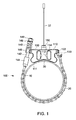
- FIG. 1 shows a clamp 100 for attaching (e.g., coupling) a probe 30 to the outer surface of a pipe 10 (e.g., having an outer diameter of 10" (254mm)) in an exemplary embodiment of the invention.
- a pipe 10 e.g., having an outer diameter of 10" (254mm)
- the exemplary embodiment of the clamp is shown coupling a probe 30 to the outer surface of a pipe 10
- the clamp 100 can be used to attach a variety of devices to a variety of circular structures besides probes 30 or other nondestructive testing devices, and besides pipes (e.g., other conduits, poles, etc.).
- the probe 30 and associated probe wire 32 can be installed within a clamp body 110, which can couple the probe 30 to the outer surface of the pipe 10.
- the clamp body 110 can include a clamp body opening 116 (e.g., a hole) to receive and hold the probe 30 against the outer surface of the pipe 10.
- the probe 30 can be coupled to the outer surface of the pipe 10 through an acoustically conductive foil (not shown) (e.g., a gold foil) or other conductive material.
- FIG. 2 shows a perspective view of the clamp body 110 shown in FIG. 1 in an exemplary embodiment of the invention.
- the clamp body 110 can be made of 303 stainless steel.
- the clamp body 110 can include transverse openings 114 to reduce the weight of the clamp body 110 and to make the clamp body 110 easier to handle during installation.
- the clamp body 100 can also include a clamp body opening 116 that includes clamp body opening longitudinal slots 118 into which the probe 30 can be installed.
- FIG. 3 shows the portion of the probe 30 installed in the clamp body 110 shown in FIG. 1 in an exemplary embodiment of the invention.
- the backside of the probe 30 can be held by a probe ring 34 with probe ring tabs 36 that slide into the clamp body opening 116 and clamp body opening longitudinal slots 118 when the probe 30 is inserted into the clamp body 110 shown in FIG. 2 .
- a certain coupling force e.g., 1,000 lbs
- a range of coupling forces is necessary to ensure a proper coupling between the probe 30 and the outer surface of the pipe 10.
- a pushing nut 150 through which the probe cable 32 can pass can be threaded into a threaded portion of the clamp body opening 116 to apply force down onto the probe 30 through the probe ring 34 until the desired coupling force between the probe 30 and the outer surface of the pipe 10 is achieved.
- the pushing nut 150 comprises a hexagonal nut on top of a cylindrical body, at least a portion of which is threaded.
- one or more spring washers 152 also referred to as cupped spring washers, Belleville washers, Belleville springs, or coned-disk springs
- cupped spring washers also referred to as cupped spring washers, Belleville washers, Belleville springs, or coned-disk springs
- each spring washer 152 is rated to provide 700 lbs. of force
- two spring washers 152 can be used.
- calibration and other testing can be performed to confirm that the actual coupling force between the probe 30 and the outer surface of the pipe 10 is within the acceptable range of coupling forces.
- the spring washers 152 can maintain the required coupling force between the probe 30 and the outer surface of the pipe 10 within an acceptable range even if the outer diameter of the pipe 10 changes based on changes in temperature or other factors. For example, without the spring washers 152, if the temperature of the pipe 10 decreased such that the outer diameter of the pipe 10 also decreased, the coupling force between the probe 30 and the outer surface of the pipe 10 would decrease as the outer surface of pipe 10 moved away from the probe 30. However, in the inventive clamp 100, the spring washers 152 can expand as the outer surface of pipe 10 moves away from the probe 30 to press down on the probe 10 to maintain the required coupling force between the probe 30 and the outer surface of the pipe 10 to prevent movement of the probe 30 away from the outer surface of the pipe 10.
- the clamp body 110 can include two clamp body wrench slots 112 to receive a wrench used to prevent the clamp body 110 from rotating with the pushing nut 150. These features can prevent the probe 30 from twisting against the outer surface of the pipe 10 during the threading of the pushing nut 150 down into the clamp body opening 116 and damaging the delay of the probe 30 or the foil that may be installed between the probe 30 and the outer surface of the pipe 10.
- the bottom surface 111 of the clamp body 110 is configured (e.g., curved) to rest on the outer surface of pipes 10 over a wide range of outer diameters.
- the radius of curvature of the clamp body bottom surface 111 can be designed to be substantially the same as the radius of curvature of the outer surface of the smallest diameter pipe 10 that the clamp body 110 may be used with.
- the radius of curvature of the clamp body bottom surface 111 can be designed so that the ends of the bottom surface 111 contact the outer surface of the largest diameter pipe 10 that the clamp body 110 may be used with while allowing the probe 30 to extend far enough below the clamp body bottom surface 111 to couple with the outer surface of the pipe 10 (as shown in FIG. 4 for the pipe having a larger outer diameter (e.g., 20" (508mm)).
- the clamp body 110 is attached to the outer surface of the pipe 10 using a strap 20 placed on the circumference of the outer surface of the pipe 10.
- the strap 20 used to attach a single clamp body 110 to the outer surface of the pipe 10 is a roller chain, similar to a chain used on a bicycle.
- the strap 20 can be made of carbon steel.
- Other straps 20 e.g., cables, ropes, other types of chains, etc.
- the strap 20 can be coated to prevent corrosion on the strap 20 and the outer surface of the pipe 10 contacted by the strap 20.
- the flexibility provided by the design of the clamp body 110 and the strap 20 allows a single clamp 100 to be used on pipes 10 over a wide range of outer diameters by adjusting the length of the strap 20.
- a plurality of straps 20 can be used to join the clamp bodies 110
- a hook 130 or other fastener can be attached for fastening the clamp body 110 to the strap 20.
- the strap 20 is a chain or other linked structure
- one of the links in the chain can be slid over the hook 130 or fixedly fastened to the hook 130.
- the hook 130 is pivotally attached to the clamp body 110 by a hook pivot 122 that can rotate to provide the appropriate angle of connection to the strap 20 determined by the outer diameter of the pipe 10.
- the angle of the hook 130 provided by the hook pivot 122 for the smaller pipe shown in FIG. 1 is smaller than the angle of the hook 130 provided by the hook pivot 122 for the larger pipe shown in FIG. 4 .
- the configuration of the hook 130 and hook pivot 122 can be varied to suit different applications, including the use of a bolt arm pivoting on the clamp body 110, a bolt extending through the bolt arm with a hook on the end of it to attach to the strap 20, and a nut at the opposite end of the hook.
- a bolt 142 can be attached for connecting the clamp body 110 to the strap 20.
- the bolt 142 extends through a bolt arm 146.
- One end of the bolt 142 can extend through and below the bolt arm 146 and can be threaded into, or otherwise attached, to a strap arm 144 that is fastened to the strap 20.
- the bolt arm 146 is pivotally attached to the clamp body 110 by a bolt arm pivot 120 that can rotate to provide the appropriate angle of connection to the strap 20 determined by the outer diameter of the pipe 10. For example, the angle of the strap arm 144 provided by the bolt arm pivot 120 for the smaller pipe shown in FIG.
- the angle of the strap arm 144 provided by the bolt arm pivot 120 for the larger pipe shown in FIG. 4 is smaller than the angle of the strap arm 144 provided by the bolt arm pivot 120 for the larger pipe shown in FIG. 4 .
- the strap 20 is a chain or other linked structure
- one of the links in the chain can be slid over the strap arm 144 or fixedly fastened to the strap arm 144.
- the other end of the bolt 142 can extend through and above the bolt arm 146 for a sufficient distance to allow for the installation of a compression coil spring 140 or other spring between the bolt arm 146 and a nut 148 on the end of the bolt 142.
- one or more washers 149 can be used to distribute the load between the nut 148 and the compression coil spring 140.
- the compression coil spring 140 can be a 2" (50.8mm) long spring that can be compressed a maximum of approximately 0.5" (12.7mm) under a load of 1,500 lbs.
- the compression coil spring 140 can be chosen to withstand a smaller load (e.g., 700 lbs).
- the nut 148 can be tightened down onto the bolt 142 by compressing the compression coil spring 140 to a point between its fully extended position (0.0" (0mm)) and its fully compressed position (0.5" (12.7mm)) (e.g., 0.25" (6.35mm)).
- the compression coil spring 140 As the compression coil spring 140 is compressed, it exerts an upward force on the nut 148 (or washers 149), which exerts an upward force on the bolt 142 and attached strap arm 144, increasing the tension on the strap 20 attached to the outer surface of the pipe 10, and thereby increasing the attachment force between the clamp body 110 and the outer surface of the pipe 10 provided by the strap 20.
- the compression coil spring 140 can maintain the attachment force between the clamp body 110 and the outer surface of the pipe 10 provided by the strap 20 within an acceptable range even if the outer diameter of the pipe 10 or the strap 20 changes based on changes in temperature or other factors, including circumstances where the outer diameter of the pipe 10 or the strap 20 change at different rates. For example, without the compression coil spring 140, if the temperature of the pipe 10 decreased such that the outer diameter of the pipe 10 also decreased at a different rate than the strap 20, the attachment force between the clamp body 110 and the outer surface of the pipe 10 provided by the strap 20 would decrease as there would be more slack in the strap 20. This may cause relative movement between the probe 30 and the outer surface of the pipe 10 that may result in decoupling of the probe 30 from the outer surface of the pipe 10.
- the compressed coil spring 140 can expand as the outer diameter of the pipe 10 thermally contracts, exerting an upward force on the nut 148 (or washers 149), which exerts an upward force on the bolt 142 and attached strap arm 144, maintaining sufficient attachment force between the clamp body 110 and the outer surface of the pipe 10 provided by the strap 20 to prevent movement of the clamp body 110 along the outer surface of the pipe 10.
- the compression coil spring 140 if the temperature of the pipe 10 increased such that the outer diameter of the pipe 10 also increased at a different rate than the strap 20, the attachment force between the clamp body 110 and the outer surface of the pipe 10 provided by the strap 20 might increase as there would be increased force on the strap 20. The increase in force could be significant enough to damage the strap 20 and the probe 30.
- the compressed coil spring 140 can contract as the outer diameter of the pipe 10 expends, allowing the bolt 142 and attached strap arm 144 to extend downward, decreasing the tension on the strap 20 attached to the outer surface of the pipe 10 to maintain sufficient attachment force between the clamp body 110 and the outer surface of the pipe 10 provided by the strap 20 to prevent movement of the clamp body 110 along the outer surface of the pipe 10.
- FIG. 4 shows a multi-probe clamp 200 for coupling a plurality of probes 30 to the outer surface of a pipe 10 having an outer diameter of 20" (508mm)) in an exemplary embodiment of the invention.
- existing bolt or U-bolt metal clamp designs can only accommodate one or two probes 30 on the circumference of the outer surface of a pipe 10 at a particular location (e.g., on the top and bottom of the pipe, but not on the sides, or on the left side and right side of the pipe, but not on the top and bottom)
- the inventive clamp 100 can accommodate at least four probes 30 joined together by a plurality of straps 20 placed on the circumference of the outer surface of a pipe 10.
- the ability to accommodate more probes 30 increases the reliability of corrosion/erosion monitoring as different areas of pipes 10 (i.e., top, bottom, left side, right side) experience different amounts of corrosion/erosion.
Landscapes
- Engineering & Computer Science (AREA)
- General Engineering & Computer Science (AREA)
- Mechanical Engineering (AREA)
- Physics & Mathematics (AREA)
- Health & Medical Sciences (AREA)
- Life Sciences & Earth Sciences (AREA)
- Chemical & Material Sciences (AREA)
- Analytical Chemistry (AREA)
- Biochemistry (AREA)
- General Health & Medical Sciences (AREA)
- General Physics & Mathematics (AREA)
- Immunology (AREA)
- Pathology (AREA)
- Clamps And Clips (AREA)
- Investigating Or Analyzing Materials By The Use Of Ultrasonic Waves (AREA)
Abstract
Description
- The subject matter disclosed herein relates to an apparatus for attaching a device to the outer surface of a circular structure, and more particularly, to an apparatus for coupling a nondestructive testing device to the outer surface of a pipe.
- Several industries (e.g., oil and gas, refinery, chemical, power generation) require the transport of fluid (e.g., liquids or gases) through pipes. Nondestructive testing devices can be placed on the outer surface of these pipes to monitor corrosion/erosion of the pipes, including corrosion/erosion on the interior of pipe walls. In many cases, the probe or other nondestructive testing device is permanently coupled to the outer surface of the pipe at a single location to continuously monitor corrosion/erosion at that location to determine pipe corrosion/erosion rates and to determine whether that pipe location is in need of preventative maintenance to prevent a pipe failure.
- One example of a nondestructive testing device used to monitor corrosion/erosion of a pipe is an ultrasonic testing device. When conducting ultrasonic testing of a pipe, an ultrasonic pulse is emitted from a probe coupled to the outer surface of the pipe and passed through the pipe wall. As the ultrasonic pulse passes into and through the pipe wall, various pulse reflections called echoes are reflected back to the probe as the pulse interacts with the outer surface of the pipe, internal structures within the pipe wall, and with the back wall of the pipe wall. The echo signals can be displayed on a screen with echo amplitudes appearing as vertical traces and time of flight or distance as horizontal traces. By tracking the time difference between the transmission of the ultrasonic pulse and the receipt of the echoes, various characteristics of the pipe can be determined, including pipe wall thickness. If the thickness of the pipe wall at the location of the ultrasonic testing device decreases over time (e.g., as would be shown be a reduction in the time of flight of the back wall echo), this can be an indication of corrosion/erosion.
- Since much of the analysis in ultrasonic testing, as well as other nondestructive testing techniques (e.g., electromagnetic, infrared/thermal, radiographic, etc.), is based on comparisons of current measurements to past measurements or to known measurements based on calibration or original dimensions, it is necessary to ensure that the position and coupling of the probe in relation to the outer surface of the pipe remain fixed and unchanged over time. For example, if the probe remains coupled to the outer surface of the pipe but moves along the outer surface of the pipe from one location to another, this can lead to inaccurate results based on the comparison of data from two different locations on the outer surface of the pipe. Similarly, if the probe becomes decoupled from the outer surface of the pipe or the coupling force between the probe and the outer surface of the pipe changes, this can result to inaccurate results based on the comparison of data from different coupling positions on the outer surface of the pipe or different coupling forces. For instance, if the probe was not properly coupled to the outer surface of the pipe, this could lead to inaccurate time of flight data that would fail to accurately indicate the amount of corrosion/erosion at a location of the pipe. In some cases, the decoupling could be so significant that it would prevent the ability of the probe to transmit the ultrasonic pulse through the pipe wall to conduct any testing.
- One existing solution for coupling a probe or other nondestructive testing device to the outer surface of a pipe is a metal clamp that includes a U-bolt fastened to a clamp body, wherein the bend of the U-bolt is fitted around one side (e.g., the bottom) of the outer surface of the pipe and the threaded ends of the U-bolt are fastened to the clamp body that extends from one threaded end of the U-bolt to the other across the opposite side (e.g., the top) of the outer surface of the pipe. In some installations where a probe is required on opposite sides of the pipe, rather than use a U-bolt, conventional bolts can attach one clamp body on one side of the pipe to another clamp body on the opposite side of the pipe. Since the clamp bodies, U-bolts, and/or bolts used in this existing metal clamp are sized based on the outer diameter of the outer surface of the pipe (e.g., in the range of 2" (50.8mm) to 40" (1,016mm)), a single metal clamp design can typically only be used for two or three different sized pipes (e.g., one metal clamp can only be used for 6" (152.4mm), 8" (203.2mm), and 10" (254mm) pipes). Also, given the configuration of the existing metal clamp, a single metal clamp design can typically only be used to accommodate one or two probes on the circumference of the outer surface of the pipe at a particular location (e.g., on the top and bottom of the pipe, but not on the sides, or on the left side and right side of the pipe, but not on the top and bottom).
- In the existing bolt or U-bolt metal clamp, the portion of the clamp body contacting the outer surface of the pipe can include an opening into which the probe can be installed. In some installations, a metal block is placed over the cavity after the probe is installed in the cavity. One or more bolts can then be tightened to apply force down onto the probe until the desired coupling force between the probe and the outer surface of the pipe is achieved. While this existing bolt or U-bolt metal clamp is capable in some cases of ensuring that the position and coupling of the probe in relation to the outer surface of the pipe remain fixed and unchanged over time, there can be circumstances where this is not the case. For example, the use of multiple bolts on the clamp body to establish the desired coupling force introduces the possibility that, if one bolt is tightened more than another, certain parts of the probe may be coupled to the outer surface of the pipe at different coupling forces than other parts of the probe.
- Changes in temperature of the existing clamp and the pipe over time can also result in changes in the position and coupling of the probe in relation to the pipe by changing the shape of the metal clamp and the pipe. For example, if the fluid being transported through the pipe is at a high temperature (e.g., greater than 350°C), the pipe can be heated to this high temperature, resulting in thermal expansion of the pipe (i.e., increase in the outer diameter of the pipe), which may bend or otherwise deform the clamp body or U-bolts/bots of the existing metal clamp. In addition, if the pipe is heated to this high temperature, the existing metal clamp, which is in contact with the outer surface of the pipe, can also be heated to this high temperature, making the existing metal clamp more malleable and likely to bend or otherwise deform. To the extent that the pipe and existing metal clamp are made of different materials (e.g., stainless steel, carbon steel), the effect of the high temperature on the pipe and existing metal clamp may differ (e.g., different amounts and rates of thermal expansion and contraction). Even if the pipe and existing metal clamp are made of the same material, the effect of the high temperature on the pipe and existing metal clamp may differ based on the different ambient conditions of the pipe and the existing metal clamp. The continuous temperature cycling (e.g., thermal expansion and contraction) of the pipe and the existing metal clamp can result in changes in the position and coupling of the probe in relation to the pipe. In some cases, the temperature cycling may be so significant over time that the probe becomes decoupled from the outer surface of the pipe, requiring that the existing metal clamp be removed and replaced in a laborious process. In order to minimize temperature cycling, the size and thickness of the existing metal clamp can be significantly increased, which increases the difficulty of handling and installing the clamp and undesirably increases the weight of the clamp on the pipe.
- It would be advantageous to provide an apparatus for attaching a device to the outer surface of a pipe that does not have the disadvantages associated with the existing metal clamp.
- An apparatus for attaching a device to a circular structure is disclosed. In one embodiment, the apparatus includes a clamp body attached to the outer surface of the circular structure using a strap, which can be attached to the clamp body using a spring that maintains an attachment force to prevent movement of the clamp body over a wide range of temperatures and temperature cycling of the circular structure and the strap. In one embodiment, the device can be installed in the clamp body and coupled to the outer surface of the circular structure using one or more spring washers that maintain an attachment force between the device and the outer surface of the circular structure to prevent detachment of the device from the outer surface of the circular structure over a wide range of temperatures and temperature cycling of the circular structure.
- So that the manner in which the features of the invention can be understood, a detailed description of the invention may be had by reference to certain embodiments, some of which are illustrated in the accompanying drawings. It is to be noted, however, that the drawings illustrate only certain embodiments of this invention and are therefore not to be considered limiting of its scope, for the scope of the invention encompasses other equally effective embodiments. The drawings are not necessarily to scale, emphasis generally being placed upon illustrating the features of certain embodiments of invention. Thus, for further understanding of the invention, reference can be made to the following detailed description, read in connection with the drawings in which:
-
FIG. 1 shows a clamp for coupling a probe to the outer surface of a pipe in an exemplary embodiment of the invention. -
FIG. 2 shows a perspective view of the clamp body shown inFIG. 1 in an exemplary embodiment of the invention. -
FIG. 3 shows the portion of the probe installed in the clamp body shown inFIG. 1 in an exemplary embodiment of the invention. -
FIG. 4 shows a multi-probe clamp for coupling a plurality of probes to the outer surface of a pipe in an exemplary embodiment of the invention. -
FIG. 1 shows aclamp 100 for attaching (e.g., coupling) aprobe 30 to the outer surface of a pipe 10 (e.g., having an outer diameter of 10" (254mm)) in an exemplary embodiment of the invention. Although the exemplary embodiment of the clamp is shown coupling aprobe 30 to the outer surface of apipe 10, theclamp 100 can be used to attach a variety of devices to a variety of circular structures besidesprobes 30 or other nondestructive testing devices, and besides pipes (e.g., other conduits, poles, etc.). As shown inFIG. 1 , theprobe 30 and associatedprobe wire 32 can be installed within aclamp body 110, which can couple theprobe 30 to the outer surface of thepipe 10. In one embodiment, theclamp body 110 can include a clamp body opening 116 (e.g., a hole) to receive and hold theprobe 30 against the outer surface of thepipe 10. Theprobe 30 can be coupled to the outer surface of thepipe 10 through an acoustically conductive foil (not shown) (e.g., a gold foil) or other conductive material. -
FIG. 2 shows a perspective view of theclamp body 110 shown inFIG. 1 in an exemplary embodiment of the invention. In one embodiment, theclamp body 110 can be made of 303 stainless steel. Theclamp body 110 can includetransverse openings 114 to reduce the weight of theclamp body 110 and to make theclamp body 110 easier to handle during installation. Theclamp body 100 can also include a clamp body opening 116 that includes clamp body openinglongitudinal slots 118 into which theprobe 30 can be installed. -
FIG. 3 shows the portion of theprobe 30 installed in theclamp body 110 shown inFIG. 1 in an exemplary embodiment of the invention. The backside of theprobe 30 can be held by aprobe ring 34 withprobe ring tabs 36 that slide into the clamp body opening 116 and clamp body openinglongitudinal slots 118 when theprobe 30 is inserted into theclamp body 110 shown inFIG. 2 . In many installations, a certain coupling force (e.g., 1,000 lbs) or a range of coupling forces is necessary to ensure a proper coupling between theprobe 30 and the outer surface of thepipe 10. A pushingnut 150 through which theprobe cable 32 can pass can be threaded into a threaded portion of the clamp body opening 116 to apply force down onto theprobe 30 through theprobe ring 34 until the desired coupling force between theprobe 30 and the outer surface of thepipe 10 is achieved. In one embodiment shown inFIG. 3 , the pushingnut 150 comprises a hexagonal nut on top of a cylindrical body, at least a portion of which is threaded. As shown inFIG. 3 , one or more spring washers 152 (also referred to as cupped spring washers, Belleville washers, Belleville springs, or coned-disk springs) can be installed between the pushingnut 150 and theprobe ring 34 in the clamp body opening 116 to apply the desired coupling force to theprobe 30. For example, if a coupling force of 1,000 lbs. is required and eachspring washer 152 is rated to provide 700 lbs. of force, twospring washers 152 can be used. During installation, calibration and other testing can be performed to confirm that the actual coupling force between theprobe 30 and the outer surface of thepipe 10 is within the acceptable range of coupling forces. - After installation, the
spring washers 152 can maintain the required coupling force between theprobe 30 and the outer surface of thepipe 10 within an acceptable range even if the outer diameter of thepipe 10 changes based on changes in temperature or other factors. For example, without thespring washers 152, if the temperature of thepipe 10 decreased such that the outer diameter of thepipe 10 also decreased, the coupling force between theprobe 30 and the outer surface of thepipe 10 would decrease as the outer surface ofpipe 10 moved away from theprobe 30. However, in theinventive clamp 100, thespring washers 152 can expand as the outer surface ofpipe 10 moves away from theprobe 30 to press down on theprobe 10 to maintain the required coupling force between theprobe 30 and the outer surface of thepipe 10 to prevent movement of theprobe 30 away from the outer surface of thepipe 10. - As the pushing
nut 150 is threaded down onto theprobe ring 34 and theprobe 30, theprobe ring tabs 36 received by the clamp body openinglongitudinal slots 118 prevent theprobe 30 from rotating with the pushingnut 150. As shown inFIG. 2 , theclamp body 110 can include two clampbody wrench slots 112 to receive a wrench used to prevent theclamp body 110 from rotating with the pushingnut 150. These features can prevent theprobe 30 from twisting against the outer surface of thepipe 10 during the threading of the pushingnut 150 down into theclamp body opening 116 and damaging the delay of theprobe 30 or the foil that may be installed between theprobe 30 and the outer surface of thepipe 10. - The
bottom surface 111 of theclamp body 110 is configured (e.g., curved) to rest on the outer surface ofpipes 10 over a wide range of outer diameters. For example, the radius of curvature of the clampbody bottom surface 111 can be designed to be substantially the same as the radius of curvature of the outer surface of thesmallest diameter pipe 10 that theclamp body 110 may be used with. Similarly, the radius of curvature of the clampbody bottom surface 111 can be designed so that the ends of thebottom surface 111 contact the outer surface of thelargest diameter pipe 10 that theclamp body 110 may be used with while allowing theprobe 30 to extend far enough below the clampbody bottom surface 111 to couple with the outer surface of the pipe 10 (as shown inFIG. 4 for the pipe having a larger outer diameter (e.g., 20" (508mm)). - Returning to
FIG. 1 , theclamp body 110 is attached to the outer surface of thepipe 10 using astrap 20 placed on the circumference of the outer surface of thepipe 10. In the exemplary embodiment shown inFIG. 1 , thestrap 20 used to attach asingle clamp body 110 to the outer surface of thepipe 10 is a roller chain, similar to a chain used on a bicycle. In one embodiment, thestrap 20 can be made of carbon steel. Other straps 20 (e.g., cables, ropes, other types of chains, etc.) can be also be used. In one embodiment, thestrap 20 can be coated to prevent corrosion on thestrap 20 and the outer surface of thepipe 10 contacted by thestrap 20. The flexibility provided by the design of theclamp body 110 and thestrap 20 allows asingle clamp 100 to be used onpipes 10 over a wide range of outer diameters by adjusting the length of thestrap 20. In an embodiment including a plurality of clamp bodies 110 (seeFIG. 4 ), a plurality ofstraps 20 can be used to join theclamp bodies 110 - In one embodiment, on one end of the
clamp body 110, ahook 130 or other fastener can be attached for fastening theclamp body 110 to thestrap 20. In the case where thestrap 20 is a chain or other linked structure, one of the links in the chain can be slid over thehook 130 or fixedly fastened to thehook 130. In the exemplary embodiment shown inFIG. 1 , thehook 130 is pivotally attached to theclamp body 110 by ahook pivot 122 that can rotate to provide the appropriate angle of connection to thestrap 20 determined by the outer diameter of thepipe 10. For example, the angle of thehook 130 provided by thehook pivot 122 for the smaller pipe shown inFIG. 1 is smaller than the angle of thehook 130 provided by thehook pivot 122 for the larger pipe shown inFIG. 4 . The configuration of thehook 130 andhook pivot 122 can be varied to suit different applications, including the use of a bolt arm pivoting on theclamp body 110, a bolt extending through the bolt arm with a hook on the end of it to attach to thestrap 20, and a nut at the opposite end of the hook. - In one embodiment, on the other end of the
clamp body 110, abolt 142 can be attached for connecting theclamp body 110 to thestrap 20. In the exemplary embodiment shown inFIG. 1 , thebolt 142 extends through abolt arm 146. One end of thebolt 142 can extend through and below thebolt arm 146 and can be threaded into, or otherwise attached, to astrap arm 144 that is fastened to thestrap 20. Thebolt arm 146 is pivotally attached to theclamp body 110 by abolt arm pivot 120 that can rotate to provide the appropriate angle of connection to thestrap 20 determined by the outer diameter of thepipe 10. For example, the angle of thestrap arm 144 provided by thebolt arm pivot 120 for the smaller pipe shown inFIG. 1 is smaller than the angle of thestrap arm 144 provided by thebolt arm pivot 120 for the larger pipe shown inFIG. 4 . In the case where thestrap 20 is a chain or other linked structure, one of the links in the chain can be slid over thestrap arm 144 or fixedly fastened to thestrap arm 144. The other end of thebolt 142 can extend through and above thebolt arm 146 for a sufficient distance to allow for the installation of acompression coil spring 140 or other spring between thebolt arm 146 and anut 148 on the end of thebolt 142. In one embodiment, one ormore washers 149 can be used to distribute the load between thenut 148 and thecompression coil spring 140. In one embodiment used for a range of larger diameter pipes, thecompression coil spring 140 can be a 2" (50.8mm) long spring that can be compressed a maximum of approximately 0.5" (12.7mm) under a load of 1,500 lbs. For smaller diameter pipes, thecompression coil spring 140 can be chosen to withstand a smaller load (e.g., 700 lbs). - During installation of the
clamp body 110 onto the outer surface of thepipe 10, after the appropriate lengths ofstraps 20 have been attached to theclamp body 110, thenut 148 can be tightened down onto thebolt 142 by compressing thecompression coil spring 140 to a point between its fully extended position (0.0" (0mm)) and its fully compressed position (0.5" (12.7mm)) (e.g., 0.25" (6.35mm)). As thecompression coil spring 140 is compressed, it exerts an upward force on the nut 148 (or washers 149), which exerts an upward force on thebolt 142 and attachedstrap arm 144, increasing the tension on thestrap 20 attached to the outer surface of thepipe 10, and thereby increasing the attachment force between theclamp body 110 and the outer surface of thepipe 10 provided by thestrap 20. - After installation, the
compression coil spring 140 can maintain the attachment force between theclamp body 110 and the outer surface of thepipe 10 provided by thestrap 20 within an acceptable range even if the outer diameter of thepipe 10 or thestrap 20 changes based on changes in temperature or other factors, including circumstances where the outer diameter of thepipe 10 or thestrap 20 change at different rates. For example, without thecompression coil spring 140, if the temperature of thepipe 10 decreased such that the outer diameter of thepipe 10 also decreased at a different rate than thestrap 20, the attachment force between theclamp body 110 and the outer surface of thepipe 10 provided by thestrap 20 would decrease as there would be more slack in thestrap 20. This may cause relative movement between theprobe 30 and the outer surface of thepipe 10 that may result in decoupling of theprobe 30 from the outer surface of thepipe 10. However, in theinventive clamp 100, thecompressed coil spring 140 can expand as the outer diameter of thepipe 10 thermally contracts, exerting an upward force on the nut 148 (or washers 149), which exerts an upward force on thebolt 142 and attachedstrap arm 144, maintaining sufficient attachment force between theclamp body 110 and the outer surface of thepipe 10 provided by thestrap 20 to prevent movement of theclamp body 110 along the outer surface of thepipe 10. Similarly, without thecompression coil spring 140, if the temperature of thepipe 10 increased such that the outer diameter of thepipe 10 also increased at a different rate than thestrap 20, the attachment force between theclamp body 110 and the outer surface of thepipe 10 provided by thestrap 20 might increase as there would be increased force on thestrap 20. The increase in force could be significant enough to damage thestrap 20 and theprobe 30. However, in theinventive clamp 100, thecompressed coil spring 140 can contract as the outer diameter of thepipe 10 expends, allowing thebolt 142 and attachedstrap arm 144 to extend downward, decreasing the tension on thestrap 20 attached to the outer surface of thepipe 10 to maintain sufficient attachment force between theclamp body 110 and the outer surface of thepipe 10 provided by thestrap 20 to prevent movement of theclamp body 110 along the outer surface of thepipe 10. -
FIG. 4 shows amulti-probe clamp 200 for coupling a plurality ofprobes 30 to the outer surface of apipe 10 having an outer diameter of 20" (508mm)) in an exemplary embodiment of the invention. While existing bolt or U-bolt metal clamp designs can only accommodate one or twoprobes 30 on the circumference of the outer surface of apipe 10 at a particular location (e.g., on the top and bottom of the pipe, but not on the sides, or on the left side and right side of the pipe, but not on the top and bottom), theinventive clamp 100 can accommodate at least fourprobes 30 joined together by a plurality ofstraps 20 placed on the circumference of the outer surface of apipe 10. The ability to accommodatemore probes 30 increases the reliability of corrosion/erosion monitoring as different areas of pipes 10 (i.e., top, bottom, left side, right side) experience different amounts of corrosion/erosion. - This written description uses examples to disclose the invention, including the best mode, and also to enable any person skilled in the art to practice the invention, including making and using any devices or systems and performing any incorporated methods. The patentable scope of the invention is defined by the claims, and may include other examples that occur to those skilled in the art. Such other examples are intended to be within the scope of the claims if they have structural elements that do not differ from the literal language of the claims, or if they include equivalent structural elements with insubstantial differences from the literal language of the claims.
- For completeness, various aspects of the invention are now set out in the following numbered clauses:
- 1. An apparatus for attaching a device to a circular structure, wherein the apparatus comprises:
- a clamp body comprising a first opening configured to receive the device, wherein the bottom surface of the clamp body is configured to rest on the outer surface of the circular structure;
- one or more straps configured to be placed on the circumference of the outer surface of the circular structure, wherein a first end of the one or more straps is fastened to a first fastener attached to a first end of the clamp body and a second end of the one or more straps is fastened to a second fastener;
- a bolt extending through a bolt arm attached to a second end of the clamp body, wherein the first end of the bolt below the bolt arm is attached to the second fastener and the second end of the bolt above the bolt arm is attached to a nut;
- a spring compressed between the nut and the bolt arm, wherein the spring maintains an attachment force between the clamp body and the outer surface of the circular structure provided by the one or more straps to prevent movement of the clamp body along the outer surface of the circular structure;
- a pushing nut in the first opening for applying force on the device until the device is attached to the outer surface of the circular structure; and
- a spring washer in the first opening between the pushing nut and the device, wherein the spring washer maintains an attachment force between the device and the outer surface of the circular structure provided by the pushing nut to prevent detachment of the device from the outer surface of the circular structure.
- 2. The apparatus of clause 1, wherein the clamp body further comprises a plurality of wrench slots to receive a wrench to prevent the clamp body from rotating with the pushing nut.
- 3. The apparatus of clause 1, wherein the clamp body further comprises a second opening to reduce the weight of the clamp body and to make the clamp body easier to handle during installation.
- 4. The apparatus of clause 1, further comprising a ring between the device and the spring washer for holding the backside of the device.
- 5. The apparatus of clause 4, wherein the ring further comprises a tab and wherein the first opening further comprises a longitudinal slot for receiving the tab of the ring to prevent the device from rotating with the pushing nut.
- 6. The apparatus of clause 1, wherein the one or more straps are chains.
- 7. The apparatus of clause 1, wherein the first fastener is a hook pivotally attached to the first end of the clamp body.
- 8. The apparatus of clause 1, wherein the bolt arm is pivotally attached to the second end of the clamp body.
- 9. The apparatus of clause 1, wherein the pushing nut comprises a hexagonal nut on top of a cylindrical body.
- 10. The apparatus of clause 1, wherein the circular structure is a pipe.
- 11. The apparatus of clause 1, wherein the device is a nondestructive testing probe.
- 12. An apparatus for attaching a device to a circular structure, wherein the apparatus comprises:
- a clamp body comprising a first opening configured to receive the device, wherein the bottom surface of the clamp body is configured to rest on the outer surface of the circular structure;
- one or more straps configured to be placed on the circumference of the outer surface of the circular structure, wherein a first end of the one or more straps is fastened to a first fastener attached to a first end of the clamp body and a second end of the one or more straps is fastened to a second fastener;
- a bolt extending through a bolt arm attached to a second end of the clamp body, wherein the first end of the bolt below the bolt arm is attached to the second fastener and the second end of the bolt above the bolt arm is attached to a nut; and
- a spring compressed between the nut and the bolt arm, wherein the spring maintains an attachment force between the clamp body and the outer surface of the circular structure provided by the one or more straps to prevent movement of the clamp body along the outer surface of the circular structure.
- 13. The apparatus of clause 12, further comprising:
- a pushing nut in the first opening for applying force on the device until the device is attached to the outer surface of the circular structure; and
- a spring washer in the first opening between the pushing nut and the device, wherein the spring washer maintains an attachment force between the device and the outer surface of the circular structure provided by the pushing nut to prevent detachment of the device from the outer surface of the circular structure.
- 14. The apparatus of clause 13, further comprising a ring between the device and the spring washer for holding the backside of the device.
- 15. The apparatus of clause 14, wherein the ring further comprises a tab and wherein the first opening further comprises a longitudinal slot for receiving the tab of the ring to prevent the device from rotating with the pushing nut.
- 16. An apparatus for attaching a device to a circular structure, wherein the apparatus comprises:
- a clamp body comprising a first opening configured to receive the device, wherein the bottom surface of the clamp body is configured to rest on the outer surface of the circular structure;
- one or more straps configured to be placed on the circumference of the outer surface of the circular structure, wherein a first end of the one or more straps is fastened to a first fastener attached to a first end of the clamp body and a second end of the one or
- more straps is fastened to a second fastener attached to a second end of the clamp body;
- a pushing nut in the first opening for applying force on the device until the device is attached to the outer surface of the circular structure; and
- a spring washer in the first opening between the pushing nut and the device, wherein the spring washer maintains an attachment force between the device and the outer surface of the circular structure provided by the pushing nut to prevent detachment of the device from the outer surface of the circular structure.
- 17. The apparatus of clause 16, further comprising a ring between the device and the spring washer for holding the backside of the device.
- 18. The apparatus of clause 17, wherein the ring further comprises a tab and wherein the first opening further comprises a longitudinal slot for receiving the tab of the ring to prevent the device from rotating with the pushing nut.
Claims (11)
- An apparatus (100) for attaching a device (30) to a circular structure (10), wherein the apparatus (100) comprises:a clamp body (110) comprising a first opening (116) configured to receive the device (30), wherein the bottom surface (111) of the clamp body (110) is configured to rest on the outer surface of the circular structure (10);one or more straps (20) configured to be placed on the circumference of the outer surface of the circular structure (10), wherein a first end of the one or more straps (20) is fastened to a first fastener (130) attached to a first end of the clamp body (110) and a second end of the one or more straps (20) is fastened to a second fastener (144);a bolt (142) extending through a bolt arm (146) attached to a second end of the clamp body (110), wherein the first end of the bolt (142) below the bolt arm (146) is attached to the second fastener (144) and the second end of the bolt (142) above the bolt arm (146) is attached to a nut (148);a spring (140) compressed between the nut (148) and the bolt arm (146), wherein the spring (140) maintains an attachment force between the clamp body (110) and the outer surface of the circular structure (10) provided by the one or more straps (20) to prevent movement of the clamp body (110) along the outer surface of the circular structure (10);a pushing nut (150) in the first opening (116) for applying force on the device (30) until the device (30) is attached to the outer surface of the circular structure (10); anda spring washer (152) in the first opening (116) between the pushing nut (150) and the device (30), wherein the spring washer (152) maintains an attachment force between the device (30) and the outer surface of the circular structure (10) provided by the pushing nut (150) to prevent detachment of the device (30) from the outer surface of the circular structure (10).
- The apparatus (100) of claim 1, wherein the clamp body (110) further comprises a plurality of wrench slots (118) (112) to receive a wrench to prevent the clamp body (110) from rotating with the pushing nut (150).
- The apparatus (100) of claim 1 or 2, wherein the clamp body (110) further comprises a second opening (114) to reduce the weight of the clamp body (110) and to make the clamp body (110) easier to handle during installation.
- The apparatus (100) of any of the preceding claims, further comprising a ring (34) between the device (30) and the spring washer (152) for holding the backside of the device (30).
- The apparatus (100) of claim 4, wherein the ring (34) further comprises a tab (36) and wherein the first opening (116) further comprises a longitudinal slot (118) for receiving the tab (36) of the ring (34) to prevent the device (30) from rotating with the pushing nut (150).
- The apparatus (100) of any of the preceding claims, wherein the one or more straps (20) are chains.
- The apparatus (100) of any of the preceding claims, wherein the first fastener (130) is a hook pivotally attached to the first end of the clamp body (110).
- The apparatus (100) of any of the preceding claims, wherein the bolt arm (146) is pivotally attached to the second end of the clamp body (110).
- The apparatus (100) of any of the preceding claims, wherein the pushing nut (150) comprises a hexagonal nut on top of a cylindrical body.
- The apparatus (100) of any of the preceding claims, wherein the circular structure (10) is a pipe.
- The apparatus (100) of any of the preceding claims, wherein the device (30) is a nondestructive testing probe.
Applications Claiming Priority (1)
| Application Number | Priority Date | Filing Date | Title |
|---|---|---|---|
| US12/731,309 US8186643B2 (en) | 2010-03-25 | 2010-03-25 | Apparatus for attaching a device to a circular structure |
Publications (2)
| Publication Number | Publication Date |
|---|---|
| EP2369216A1 true EP2369216A1 (en) | 2011-09-28 |
| EP2369216B1 EP2369216B1 (en) | 2014-01-15 |
Family
ID=44210311
Family Applications (1)
| Application Number | Title | Priority Date | Filing Date |
|---|---|---|---|
| EP11159289.5A Not-in-force EP2369216B1 (en) | 2010-03-25 | 2011-03-22 | Apparatus for attaching a device to a circular structure |
Country Status (3)
| Country | Link |
|---|---|
| US (1) | US8186643B2 (en) |
| EP (1) | EP2369216B1 (en) |
| CA (1) | CA2733745A1 (en) |
Cited By (1)
| Publication number | Priority date | Publication date | Assignee | Title |
|---|---|---|---|---|
| ES2948721A1 (en) * | 2023-07-28 | 2023-09-18 | Grupo Mikalor Sl | METAL CLAMP WITH SUPPORT FOR EXTERNAL FIXING OF MEASUREMENT PROBES IN PIPES (Machine-translation by Google Translate, not legally binding) |
Families Citing this family (19)
| Publication number | Priority date | Publication date | Assignee | Title |
|---|---|---|---|---|
| US20120088587A1 (en) * | 2010-10-12 | 2012-04-12 | Zaccari Richard D | Security device and security system |
| DE102011010655B3 (en) * | 2011-02-09 | 2012-07-26 | Norma Germany Gmbh | clamp |
| US20150217154A1 (en) * | 2014-02-06 | 2015-08-06 | Performance Advantage Company, Inc. | Universal nozzle connector with an adjustable mount |
| US10773416B1 (en) * | 2016-04-26 | 2020-09-15 | Richard Lee | Split wood retention device |
| US10556301B2 (en) * | 2017-08-17 | 2020-02-11 | Steven Christopher Baker | Tube clamp assembly |
| FR3090762B1 (en) * | 2018-12-21 | 2021-03-05 | Financiere De Beaumont Fdb | Device for securing an element on a duct, securing system, installation and implementation method |
| GB2582562B (en) * | 2019-03-22 | 2021-07-21 | Novosound Ltd | Ultrasonic device |
| WO2020243055A2 (en) * | 2019-05-26 | 2020-12-03 | Oceaneering International, Inc. | System for detecting flooding in flexible tubular pipes under high pressure conditions |
| CN110469780B (en) * | 2019-07-26 | 2024-07-26 | 中国石油天然气集团公司管材研究所 | Variable diameter sensor mounting and protecting unit and device for monitoring multi-specification pipelines |
| US11592424B2 (en) * | 2019-08-28 | 2023-02-28 | Oceaneering International, Inc. | System for detecting flooding in flexible tubular pipes under high pressure conditions |
| EP3816621A1 (en) * | 2019-10-30 | 2021-05-05 | Georg Fischer Rohrleitungssysteme AG | Test of sleeve welding |
| GB202209760D0 (en) * | 2020-02-18 | 2022-08-17 | Wireman Pty Ltd | A welding jig |
| FR3127033B1 (en) * | 2021-09-10 | 2023-08-18 | Sagemcom Broadband Sas | Clamping by constrained strap |
| US20230250895A1 (en) * | 2021-12-31 | 2023-08-10 | Earl McDonald | Devices and methods to facilitate the handling of pipe sections |
| USD995339S1 (en) | 2022-07-28 | 2023-08-15 | Norgas Metering Technologies, Inc. | Clamp on ultrasonic flow meter |
| US12565904B2 (en) * | 2022-10-21 | 2026-03-03 | Rosemount Inc. | Field device mount |
| US12399054B1 (en) | 2022-11-14 | 2025-08-26 | Sunsonic, LLC | Clamp on ultrasonic flow meter |
| DE102022130628A1 (en) * | 2022-11-18 | 2024-05-23 | Endress+Hauser Flowtec Ag | Fixing device and ultrasonic measuring device |
| GB2640678A (en) * | 2024-04-30 | 2025-11-05 | Nicoustic As | Apparatus and methods for mounting sensors on a structure |
Citations (6)
| Publication number | Priority date | Publication date | Assignee | Title |
|---|---|---|---|---|
| US812625A (en) * | 1904-04-20 | 1906-02-13 | Leroy Augustus Weston | Hose and hydrant connection. |
| FR2404202A1 (en) * | 1977-09-27 | 1979-04-20 | Endress Hauser Gmbh Co | DEVICE FOR SUBJECTING A SOUND OR ULTRA-SOUND TRANSDUCER TO A CONTAINER |
| GB2021677A (en) * | 1978-05-24 | 1979-12-05 | Neiman Sa | Anti-theft devices for automobile vehicles |
| US4569497A (en) * | 1983-07-27 | 1986-02-11 | Scott Equipment Company | Meter leveling saddle |
| US5329673A (en) * | 1993-08-16 | 1994-07-19 | R. G. Ray Corporation | Self tightening hose clamp with centered spring |
| DE102004052489A1 (en) * | 2004-10-28 | 2006-05-18 | Endress + Hauser Flowtec Ag | Measuring sensor attaching device, has support housing aligned on sensor, chain laid radially about pipeline and connected to clamp of support housing and screwing unit via which adjustable force is exerted on housing |
Family Cites Families (27)
| Publication number | Priority date | Publication date | Assignee | Title |
|---|---|---|---|---|
| US1848527A (en) * | 1932-03-08 | Pipe clamp | ||
| US2379014A (en) * | 1942-12-31 | 1945-06-26 | Mueller Co | Chain lock or fastener |
| US2524436A (en) * | 1945-01-27 | 1950-10-03 | Texas Co | Clamping device |
| US2968978A (en) * | 1959-03-02 | 1961-01-24 | Charles J Wheeler | Vise |
| US3480270A (en) * | 1965-11-19 | 1969-11-25 | John B Gill | Apparatus for gripping a pipe |
| US3525158A (en) * | 1967-07-31 | 1970-08-25 | United States Steel Corp | Apparatus for aligning shafts and the like |
| US3593402A (en) * | 1968-08-19 | 1971-07-20 | Masunori Mori | Apparatus for aligning the ends of cylindrical sections to be joined |
| US3664029A (en) * | 1970-02-02 | 1972-05-23 | Harold Glucoft | Dial indicator holder |
| US3704503A (en) * | 1971-01-27 | 1972-12-05 | Jesse B Haywood | Pipe aligning clamping device |
| US4016637A (en) * | 1976-03-29 | 1977-04-12 | Swensen Donald E | Apparatus for aligning pipes |
| US4094612A (en) * | 1976-07-29 | 1978-06-13 | Widder Corporation | Tool mounting apparatus |
| US4244111A (en) * | 1979-04-24 | 1981-01-13 | Heard Sr James E | Dial indicator holders |
| US4348000A (en) * | 1979-12-11 | 1982-09-07 | Hanner Paul J | Dial indicator holder |
| US4309263A (en) * | 1980-04-03 | 1982-01-05 | Boyd Danny R | Cathodic clamp apparatus |
| US4423556A (en) * | 1981-06-11 | 1984-01-03 | Divelez Gilbert J | Alignment device |
| US4595487A (en) * | 1985-03-18 | 1986-06-17 | Kennecott Corporation | Sensing probe holder system |
| US4726575A (en) * | 1986-10-03 | 1988-02-23 | Dearman Timothy Charles | Apparatus for aligning pipes |
| US4844396A (en) * | 1987-02-20 | 1989-07-04 | Badger Meter, Inc. | Strap on pipe mounting |
| US5135208A (en) * | 1990-10-09 | 1992-08-04 | Coors Brewing Company | Chain guide apparatus for a pipe vise |
| JP3224515B2 (en) | 1997-04-22 | 2001-10-29 | 株式会社山武 | Corrosion sensor |
| US5782561A (en) * | 1997-04-30 | 1998-07-21 | Pai; Yun-Shen | Detachable pacifier with electronic thermometer |
| US6264406B1 (en) * | 1999-09-28 | 2001-07-24 | Emerson Electric Co. | Support for mounting a tool on a pipe |
| WO2002086641A1 (en) * | 2001-04-17 | 2002-10-31 | Sanyo Electric Co., Ltd. | Temperature monitoring device |
| US6641124B2 (en) * | 2002-01-23 | 2003-11-04 | Jerry Melanson | Pipe aligning device |
| US20060170215A1 (en) * | 2002-11-29 | 2006-08-03 | Martin Cousineau | Hose clamp |
| US7290805B2 (en) * | 2005-12-19 | 2007-11-06 | Highlight Tech. Corp. | Pipe clip |
| US7552643B2 (en) * | 2006-12-08 | 2009-06-30 | Centre For Nuclear Energy Research (CNER) | Device and system for corrosion detection |
-
2010
- 2010-03-25 US US12/731,309 patent/US8186643B2/en active Active
-
2011
- 2011-03-10 CA CA2733745A patent/CA2733745A1/en not_active Abandoned
- 2011-03-22 EP EP11159289.5A patent/EP2369216B1/en not_active Not-in-force
Patent Citations (6)
| Publication number | Priority date | Publication date | Assignee | Title |
|---|---|---|---|---|
| US812625A (en) * | 1904-04-20 | 1906-02-13 | Leroy Augustus Weston | Hose and hydrant connection. |
| FR2404202A1 (en) * | 1977-09-27 | 1979-04-20 | Endress Hauser Gmbh Co | DEVICE FOR SUBJECTING A SOUND OR ULTRA-SOUND TRANSDUCER TO A CONTAINER |
| GB2021677A (en) * | 1978-05-24 | 1979-12-05 | Neiman Sa | Anti-theft devices for automobile vehicles |
| US4569497A (en) * | 1983-07-27 | 1986-02-11 | Scott Equipment Company | Meter leveling saddle |
| US5329673A (en) * | 1993-08-16 | 1994-07-19 | R. G. Ray Corporation | Self tightening hose clamp with centered spring |
| DE102004052489A1 (en) * | 2004-10-28 | 2006-05-18 | Endress + Hauser Flowtec Ag | Measuring sensor attaching device, has support housing aligned on sensor, chain laid radially about pipeline and connected to clamp of support housing and screwing unit via which adjustable force is exerted on housing |
Cited By (1)
| Publication number | Priority date | Publication date | Assignee | Title |
|---|---|---|---|---|
| ES2948721A1 (en) * | 2023-07-28 | 2023-09-18 | Grupo Mikalor Sl | METAL CLAMP WITH SUPPORT FOR EXTERNAL FIXING OF MEASUREMENT PROBES IN PIPES (Machine-translation by Google Translate, not legally binding) |
Also Published As
| Publication number | Publication date |
|---|---|
| CA2733745A1 (en) | 2011-09-25 |
| EP2369216B1 (en) | 2014-01-15 |
| US8186643B2 (en) | 2012-05-29 |
| US20110233377A1 (en) | 2011-09-29 |
Similar Documents
| Publication | Publication Date | Title |
|---|---|---|
| US8186643B2 (en) | Apparatus for attaching a device to a circular structure | |
| US9581477B2 (en) | Measuring head clamp-on device for ultrasonic flow-measuring heads | |
| EP3844464B1 (en) | Temperature sensor system | |
| US11009416B2 (en) | Device for the non-intrusive measurement of the pressure of a fluid inside a cylindrical casing using chain links | |
| TR201808530T4 (en) | Pipe element with monitoring system. | |
| CN204829027U (en) | A bridgeware that is used for connector of connecting tube tip and is used for connector | |
| KR20140036430A (en) | Pipeline inspection apparatus and pipeline inspection system | |
| EP2416149B1 (en) | Method for evaluating connection state of pipe thread coupling, method for pipe thread coupling connection, and device for evaluating connection state of pipe thread coupling | |
| RU2012103911A (en) | PIPELINE CONNECTOR AND RELATED CONNECTION METHOD | |
| US11566956B2 (en) | Pressure sensor for a pipe | |
| CN205703835U (en) | A kind of pipeline jig device in ultrasonic thickness measurement system | |
| CN105021709B (en) | A kind of Pipes Using Ultrasonic Longitudinal Guided-Wave flexible array detection probe device | |
| US20140061397A1 (en) | Piggyback holdback clamp | |
| CN111198046B (en) | Elastic mounting bracket based on bimetallic strip and thermocouple using the bracket | |
| CN209439694U (en) | A kind of pipe draws centering auxiliary welding equipment over to one's side | |
| KR20150078502A (en) | Apparatus for monitoring the wall thinning of real time high temperature pipe using waveguide of sh-wave | |
| EP2574917B1 (en) | Apparatus and method for inspection of tubes in a boiler | |
| CN204925045U (en) | Flexible array detection probe unit of vertical guided wave of pipeline supersound | |
| JP2023545048A (en) | Leak detection system and its method of production and use | |
| CN118970767A (en) | A kind of anti-corrosion power protection pipeline support structure | |
| JP2025535907A (en) | Field device mounting body | |
| CN119374043A (en) | A comprehensive monitoring device for pipeline leakage suitable for different pipe diameters | |
| CN209398934U (en) | A kind of thin novel Duct fixing clamp of diameter appendix of LNG carrier | |
| CN216386030U (en) | Adherence mounting bracket and thermocouple using the same | |
| CN211146829U (en) | Temperature sensing package fixing device and air conditioner |
Legal Events
| Date | Code | Title | Description |
|---|---|---|---|
| PUAI | Public reference made under article 153(3) epc to a published international application that has entered the european phase |
Free format text: ORIGINAL CODE: 0009012 |
|
| AK | Designated contracting states |
Kind code of ref document: A1 Designated state(s): AL AT BE BG CH CY CZ DE DK EE ES FI FR GB GR HR HU IE IS IT LI LT LU LV MC MK MT NL NO PL PT RO RS SE SI SK SM TR |
|
| AX | Request for extension of the european patent |
Extension state: BA ME |
|
| 17P | Request for examination filed |
Effective date: 20120328 |
|
| GRAP | Despatch of communication of intention to grant a patent |
Free format text: ORIGINAL CODE: EPIDOSNIGR1 |
|
| INTG | Intention to grant announced |
Effective date: 20130808 |
|
| GRAS | Grant fee paid |
Free format text: ORIGINAL CODE: EPIDOSNIGR3 |
|
| GRAA | (expected) grant |
Free format text: ORIGINAL CODE: 0009210 |
|
| AK | Designated contracting states |
Kind code of ref document: B1 Designated state(s): AL AT BE BG CH CY CZ DE DK EE ES FI FR GB GR HR HU IE IS IT LI LT LU LV MC MK MT NL NO PL PT RO RS SE SI SK SM TR |
|
| REG | Reference to a national code |
Ref country code: GB Ref legal event code: FG4D Ref country code: CH Ref legal event code: EP |
|
| REG | Reference to a national code |
Ref country code: AT Ref legal event code: REF Ref document number: 650002 Country of ref document: AT Kind code of ref document: T Effective date: 20140215 |
|
| REG | Reference to a national code |
Ref country code: IE Ref legal event code: FG4D |
|
| REG | Reference to a national code |
Ref country code: DE Ref legal event code: R096 Ref document number: 602011004660 Country of ref document: DE Effective date: 20140227 |
|
| REG | Reference to a national code |
Ref country code: NO Ref legal event code: T2 Effective date: 20140115 |
|
| REG | Reference to a national code |
Ref country code: NL Ref legal event code: VDEP Effective date: 20140115 |
|
| REG | Reference to a national code |
Ref country code: AT Ref legal event code: MK05 Ref document number: 650002 Country of ref document: AT Kind code of ref document: T Effective date: 20140115 |
|
| REG | Reference to a national code |
Ref country code: LT Ref legal event code: MG4D |
|
| PG25 | Lapsed in a contracting state [announced via postgrant information from national office to epo] |
Ref country code: IS Free format text: LAPSE BECAUSE OF FAILURE TO SUBMIT A TRANSLATION OF THE DESCRIPTION OR TO PAY THE FEE WITHIN THE PRESCRIBED TIME-LIMIT Effective date: 20140515 Ref country code: LT Free format text: LAPSE BECAUSE OF FAILURE TO SUBMIT A TRANSLATION OF THE DESCRIPTION OR TO PAY THE FEE WITHIN THE PRESCRIBED TIME-LIMIT Effective date: 20140115 |
|
| PG25 | Lapsed in a contracting state [announced via postgrant information from national office to epo] |
Ref country code: FI Free format text: LAPSE BECAUSE OF FAILURE TO SUBMIT A TRANSLATION OF THE DESCRIPTION OR TO PAY THE FEE WITHIN THE PRESCRIBED TIME-LIMIT Effective date: 20140115 Ref country code: AT Free format text: LAPSE BECAUSE OF FAILURE TO SUBMIT A TRANSLATION OF THE DESCRIPTION OR TO PAY THE FEE WITHIN THE PRESCRIBED TIME-LIMIT Effective date: 20140115 Ref country code: NL Free format text: LAPSE BECAUSE OF FAILURE TO SUBMIT A TRANSLATION OF THE DESCRIPTION OR TO PAY THE FEE WITHIN THE PRESCRIBED TIME-LIMIT Effective date: 20140115 Ref country code: PT Free format text: LAPSE BECAUSE OF FAILURE TO SUBMIT A TRANSLATION OF THE DESCRIPTION OR TO PAY THE FEE WITHIN THE PRESCRIBED TIME-LIMIT Effective date: 20140515 Ref country code: CY Free format text: LAPSE BECAUSE OF FAILURE TO SUBMIT A TRANSLATION OF THE DESCRIPTION OR TO PAY THE FEE WITHIN THE PRESCRIBED TIME-LIMIT Effective date: 20140115 Ref country code: ES Free format text: LAPSE BECAUSE OF FAILURE TO SUBMIT A TRANSLATION OF THE DESCRIPTION OR TO PAY THE FEE WITHIN THE PRESCRIBED TIME-LIMIT Effective date: 20140115 Ref country code: SE Free format text: LAPSE BECAUSE OF FAILURE TO SUBMIT A TRANSLATION OF THE DESCRIPTION OR TO PAY THE FEE WITHIN THE PRESCRIBED TIME-LIMIT Effective date: 20140115 |
|
| PG25 | Lapsed in a contracting state [announced via postgrant information from national office to epo] |
Ref country code: RS Free format text: LAPSE BECAUSE OF FAILURE TO SUBMIT A TRANSLATION OF THE DESCRIPTION OR TO PAY THE FEE WITHIN THE PRESCRIBED TIME-LIMIT Effective date: 20140115 Ref country code: HR Free format text: LAPSE BECAUSE OF FAILURE TO SUBMIT A TRANSLATION OF THE DESCRIPTION OR TO PAY THE FEE WITHIN THE PRESCRIBED TIME-LIMIT Effective date: 20140115 Ref country code: LV Free format text: LAPSE BECAUSE OF FAILURE TO SUBMIT A TRANSLATION OF THE DESCRIPTION OR TO PAY THE FEE WITHIN THE PRESCRIBED TIME-LIMIT Effective date: 20140115 Ref country code: BE Free format text: LAPSE BECAUSE OF FAILURE TO SUBMIT A TRANSLATION OF THE DESCRIPTION OR TO PAY THE FEE WITHIN THE PRESCRIBED TIME-LIMIT Effective date: 20140115 |
|
| REG | Reference to a national code |
Ref country code: DE Ref legal event code: R097 Ref document number: 602011004660 Country of ref document: DE |
|
| PG25 | Lapsed in a contracting state [announced via postgrant information from national office to epo] |
Ref country code: DK Free format text: LAPSE BECAUSE OF FAILURE TO SUBMIT A TRANSLATION OF THE DESCRIPTION OR TO PAY THE FEE WITHIN THE PRESCRIBED TIME-LIMIT Effective date: 20140115 Ref country code: LU Free format text: LAPSE BECAUSE OF FAILURE TO SUBMIT A TRANSLATION OF THE DESCRIPTION OR TO PAY THE FEE WITHIN THE PRESCRIBED TIME-LIMIT Effective date: 20140322 Ref country code: RO Free format text: LAPSE BECAUSE OF FAILURE TO SUBMIT A TRANSLATION OF THE DESCRIPTION OR TO PAY THE FEE WITHIN THE PRESCRIBED TIME-LIMIT Effective date: 20140115 Ref country code: CZ Free format text: LAPSE BECAUSE OF FAILURE TO SUBMIT A TRANSLATION OF THE DESCRIPTION OR TO PAY THE FEE WITHIN THE PRESCRIBED TIME-LIMIT Effective date: 20140115 Ref country code: EE Free format text: LAPSE BECAUSE OF FAILURE TO SUBMIT A TRANSLATION OF THE DESCRIPTION OR TO PAY THE FEE WITHIN THE PRESCRIBED TIME-LIMIT Effective date: 20140115 |
|
| REG | Reference to a national code |
Ref country code: CH Ref legal event code: PL |
|
| PLBE | No opposition filed within time limit |
Free format text: ORIGINAL CODE: 0009261 |
|
| STAA | Information on the status of an ep patent application or granted ep patent |
Free format text: STATUS: NO OPPOSITION FILED WITHIN TIME LIMIT |
|
| PG25 | Lapsed in a contracting state [announced via postgrant information from national office to epo] |
Ref country code: SK Free format text: LAPSE BECAUSE OF FAILURE TO SUBMIT A TRANSLATION OF THE DESCRIPTION OR TO PAY THE FEE WITHIN THE PRESCRIBED TIME-LIMIT Effective date: 20140115 Ref country code: PL Free format text: LAPSE BECAUSE OF FAILURE TO SUBMIT A TRANSLATION OF THE DESCRIPTION OR TO PAY THE FEE WITHIN THE PRESCRIBED TIME-LIMIT Effective date: 20140115 |
|
| 26N | No opposition filed |
Effective date: 20141016 |
|
| REG | Reference to a national code |
Ref country code: FR Ref legal event code: ST Effective date: 20141128 |
|
| REG | Reference to a national code |
Ref country code: IE Ref legal event code: MM4A |
|
| PG25 | Lapsed in a contracting state [announced via postgrant information from national office to epo] |
Ref country code: FR Free format text: LAPSE BECAUSE OF NON-PAYMENT OF DUE FEES Effective date: 20140331 Ref country code: CH Free format text: LAPSE BECAUSE OF NON-PAYMENT OF DUE FEES Effective date: 20140331 Ref country code: LI Free format text: LAPSE BECAUSE OF NON-PAYMENT OF DUE FEES Effective date: 20140331 Ref country code: IE Free format text: LAPSE BECAUSE OF NON-PAYMENT OF DUE FEES Effective date: 20140322 |
|
| REG | Reference to a national code |
Ref country code: DE Ref legal event code: R097 Ref document number: 602011004660 Country of ref document: DE Effective date: 20141016 |
|
| PG25 | Lapsed in a contracting state [announced via postgrant information from national office to epo] |
Ref country code: SI Free format text: LAPSE BECAUSE OF FAILURE TO SUBMIT A TRANSLATION OF THE DESCRIPTION OR TO PAY THE FEE WITHIN THE PRESCRIBED TIME-LIMIT Effective date: 20140115 |
|
| PG25 | Lapsed in a contracting state [announced via postgrant information from national office to epo] |
Ref country code: MT Free format text: LAPSE BECAUSE OF FAILURE TO SUBMIT A TRANSLATION OF THE DESCRIPTION OR TO PAY THE FEE WITHIN THE PRESCRIBED TIME-LIMIT Effective date: 20140115 |
|
| PG25 | Lapsed in a contracting state [announced via postgrant information from national office to epo] |
Ref country code: SM Free format text: LAPSE BECAUSE OF FAILURE TO SUBMIT A TRANSLATION OF THE DESCRIPTION OR TO PAY THE FEE WITHIN THE PRESCRIBED TIME-LIMIT Effective date: 20140115 |
|
| PG25 | Lapsed in a contracting state [announced via postgrant information from national office to epo] |
Ref country code: MC Free format text: LAPSE BECAUSE OF FAILURE TO SUBMIT A TRANSLATION OF THE DESCRIPTION OR TO PAY THE FEE WITHIN THE PRESCRIBED TIME-LIMIT Effective date: 20140115 |
|
| PG25 | Lapsed in a contracting state [announced via postgrant information from national office to epo] |
Ref country code: BG Free format text: LAPSE BECAUSE OF FAILURE TO SUBMIT A TRANSLATION OF THE DESCRIPTION OR TO PAY THE FEE WITHIN THE PRESCRIBED TIME-LIMIT Effective date: 20140115 Ref country code: IT Free format text: LAPSE BECAUSE OF FAILURE TO SUBMIT A TRANSLATION OF THE DESCRIPTION OR TO PAY THE FEE WITHIN THE PRESCRIBED TIME-LIMIT Effective date: 20140115 Ref country code: GR Free format text: LAPSE BECAUSE OF FAILURE TO SUBMIT A TRANSLATION OF THE DESCRIPTION OR TO PAY THE FEE WITHIN THE PRESCRIBED TIME-LIMIT Effective date: 20140416 |
|
| PG25 | Lapsed in a contracting state [announced via postgrant information from national office to epo] |
Ref country code: TR Free format text: LAPSE BECAUSE OF FAILURE TO SUBMIT A TRANSLATION OF THE DESCRIPTION OR TO PAY THE FEE WITHIN THE PRESCRIBED TIME-LIMIT Effective date: 20140115 Ref country code: HU Free format text: LAPSE BECAUSE OF FAILURE TO SUBMIT A TRANSLATION OF THE DESCRIPTION OR TO PAY THE FEE WITHIN THE PRESCRIBED TIME-LIMIT; INVALID AB INITIO Effective date: 20110322 |
|
| PG25 | Lapsed in a contracting state [announced via postgrant information from national office to epo] |
Ref country code: MK Free format text: LAPSE BECAUSE OF FAILURE TO SUBMIT A TRANSLATION OF THE DESCRIPTION OR TO PAY THE FEE WITHIN THE PRESCRIBED TIME-LIMIT Effective date: 20140115 |
|
| PG25 | Lapsed in a contracting state [announced via postgrant information from national office to epo] |
Ref country code: AL Free format text: LAPSE BECAUSE OF FAILURE TO SUBMIT A TRANSLATION OF THE DESCRIPTION OR TO PAY THE FEE WITHIN THE PRESCRIBED TIME-LIMIT Effective date: 20140115 |
|
| PGFP | Annual fee paid to national office [announced via postgrant information from national office to epo] |
Ref country code: NO Payment date: 20230223 Year of fee payment: 13 |
|
| PGFP | Annual fee paid to national office [announced via postgrant information from national office to epo] |
Ref country code: GB Payment date: 20230222 Year of fee payment: 13 Ref country code: DE Payment date: 20230221 Year of fee payment: 13 |
|
| REG | Reference to a national code |
Ref country code: DE Ref legal event code: R119 Ref document number: 602011004660 Country of ref document: DE |
|
| GBPC | Gb: european patent ceased through non-payment of renewal fee |
Effective date: 20240322 |
|
| PG25 | Lapsed in a contracting state [announced via postgrant information from national office to epo] |
Ref country code: DE Free format text: LAPSE BECAUSE OF NON-PAYMENT OF DUE FEES Effective date: 20241001 |
|
| PG25 | Lapsed in a contracting state [announced via postgrant information from national office to epo] |
Ref country code: NO Free format text: LAPSE BECAUSE OF NON-PAYMENT OF DUE FEES Effective date: 20240331 |
|
| PG25 | Lapsed in a contracting state [announced via postgrant information from national office to epo] |
Ref country code: GB Free format text: LAPSE BECAUSE OF NON-PAYMENT OF DUE FEES Effective date: 20240322 |
|
| PG25 | Lapsed in a contracting state [announced via postgrant information from national office to epo] |
Ref country code: NO Free format text: LAPSE BECAUSE OF NON-PAYMENT OF DUE FEES Effective date: 20240331 Ref country code: GB Free format text: LAPSE BECAUSE OF NON-PAYMENT OF DUE FEES Effective date: 20240322 Ref country code: DE Free format text: LAPSE BECAUSE OF NON-PAYMENT OF DUE FEES Effective date: 20241001 |