EP2369157A1 - An adjustment and blocking system of an accelerator cable - Google Patents
An adjustment and blocking system of an accelerator cable Download PDFInfo
- Publication number
- EP2369157A1 EP2369157A1 EP11151563A EP11151563A EP2369157A1 EP 2369157 A1 EP2369157 A1 EP 2369157A1 EP 11151563 A EP11151563 A EP 11151563A EP 11151563 A EP11151563 A EP 11151563A EP 2369157 A1 EP2369157 A1 EP 2369157A1
- Authority
- EP
- European Patent Office
- Prior art keywords
- engine
- sheath
- organ
- commanded
- cable
- Prior art date
- Legal status (The legal status is an assumption and is not a legal conclusion. Google has not performed a legal analysis and makes no representation as to the accuracy of the status listed.)
- Granted
Links
Images


Classifications
-
- F—MECHANICAL ENGINEERING; LIGHTING; HEATING; WEAPONS; BLASTING
- F02—COMBUSTION ENGINES; HOT-GAS OR COMBUSTION-PRODUCT ENGINE PLANTS
- F02D—CONTROLLING COMBUSTION ENGINES
- F02D11/00—Arrangements for, or adaptations to, non-automatic engine control initiation means, e.g. operator initiated
- F02D11/02—Arrangements for, or adaptations to, non-automatic engine control initiation means, e.g. operator initiated characterised by hand, foot, or like operator controlled initiation means
-
- F—MECHANICAL ENGINEERING; LIGHTING; HEATING; WEAPONS; BLASTING
- F02—COMBUSTION ENGINES; HOT-GAS OR COMBUSTION-PRODUCT ENGINE PLANTS
- F02B—INTERNAL-COMBUSTION PISTON ENGINES; COMBUSTION ENGINES IN GENERAL
- F02B63/00—Adaptations of engines for driving pumps, hand-held tools or electric generators; Portable combinations of engines with engine-driven devices
- F02B63/02—Adaptations of engines for driving pumps, hand-held tools or electric generators; Portable combinations of engines with engine-driven devices for hand-held tools
-
- F—MECHANICAL ENGINEERING; LIGHTING; HEATING; WEAPONS; BLASTING
- F16—ENGINEERING ELEMENTS AND UNITS; GENERAL MEASURES FOR PRODUCING AND MAINTAINING EFFECTIVE FUNCTIONING OF MACHINES OR INSTALLATIONS; THERMAL INSULATION IN GENERAL
- F16C—SHAFTS; FLEXIBLE SHAFTS; ELEMENTS OR CRANKSHAFT MECHANISMS; ROTARY BODIES OTHER THAN GEARING ELEMENTS; BEARINGS
- F16C1/00—Flexible shafts; Mechanical means for transmitting movement in a flexible sheathing
- F16C1/10—Means for transmitting linear movement in a flexible sheathing, e.g. "Bowden-mechanisms"
- F16C1/22—Adjusting; Compensating length
-
- F—MECHANICAL ENGINEERING; LIGHTING; HEATING; WEAPONS; BLASTING
- F02—COMBUSTION ENGINES; HOT-GAS OR COMBUSTION-PRODUCT ENGINE PLANTS
- F02B—INTERNAL-COMBUSTION PISTON ENGINES; COMBUSTION ENGINES IN GENERAL
- F02B75/00—Other engines
- F02B75/02—Engines characterised by their cycles, e.g. six-stroke
- F02B2075/022—Engines characterised by their cycles, e.g. six-stroke having less than six strokes per cycle
- F02B2075/025—Engines characterised by their cycles, e.g. six-stroke having less than six strokes per cycle two
-
- F—MECHANICAL ENGINEERING; LIGHTING; HEATING; WEAPONS; BLASTING
- F02—COMBUSTION ENGINES; HOT-GAS OR COMBUSTION-PRODUCT ENGINE PLANTS
- F02D—CONTROLLING COMBUSTION ENGINES
- F02D9/00—Controlling engines by throttling air or fuel-and-air induction conduits or exhaust conduits
- F02D9/02—Controlling engines by throttling air or fuel-and-air induction conduits or exhaust conduits concerning induction conduits
- F02D2009/0201—Arrangements; Control features; Details thereof
- F02D2009/0255—Arrangements; Control features; Details thereof with means for correcting throttle position, e.g. throttle cable of variable length
Definitions
- the present invention relates to small work machines comprising an internal combustion engine, generally a small-cylinder two-stroke engine which activates a tool, such as for example a hedge trimmer, in which some commands comprise a lever located within the reach of the operator and at a distance from the organ which is to be commanded.
- a tool such as for example a hedge trimmer
- connection between the lever and the organ is achieved by a Bowden-type sheathed cable.
- a typical organ commanded in this way is the carburettor butterfly valve, which is activated remotely by the operator via a sheathed cable which commands the movements of the butterfly valve.
- the correct blocking of the ends of the sheath, or at least the end closer to the commanded organ, is essential for the precision of the transmitted command.
- sheath can be fixedly blocked at one of the ends thereof, generally the end closer to the command lever, and the registration of the sheath end can advantageously be performed only at the end closer to the commanded organ.
- the aim of the present invention is to make available a blocking and adjusting system of the command cable of an organ of a small internal combustion engine in which the command is remotely activated.
- the sheath of the cable of the accelerator is blocked in proximity of the commanded organ, by realising a vice between two bodies, and the position of the end of the sheath of the command cable in the vice is priorly adjusted by means of a knurled adjusting roller located in contact with the sheath and having an axis which is perpendicular to the axis of the sheath.
- One of the two bodies is in a single piece with the engine casing, or with the engine containment casing, while the other body is separate from the casing and locked by means of screws.
- the figures show that the engine 1 contained in the casing 2, in which the carburettor butterfly valve (not illustrated) is activated by the sheathed cable 3 comprising the command cable 31 contained in and slidable in the sheath 32.
- the cable 3 is brought up to the command lever, not illustrated, internally of a corrugated protection tube 4 in which the small cables 41 destined to earth the ignition for stopping the engine also run ( figure 4 ).
- the end of the sheath 32 and the tube 4 are fixed to the engine casing between a first portion 5 integrated into the casing 2 and a second portion 6 fixed to the portion 5 by means of three screws 61, 62 and 63.
- the two portions 5, 6 join on a diameter plane of the corrugated tube 4.
- Each of the portions 5 and 6 comprises, at an end thereof, a semi-cylindrical cavity 50, 60 located between the screws 61 and 62.
- the two semi-cylindrical cavities form a cylindrical cavity in which the end of the tube 4 is blocked by tightening the screws 61 and 62.
- the cable 3 extends beyond the end of the tube 4 ( figure 4 ) up to reaching in proximity of the commanded organ (not illustrated), to which the wire 31 is tensioned and fixed, by known means which are not illustrated.
- the sheath 32 of the wire 31 is maintained in position resting on a shelf 52 fashioned on the portion 5, and between two shelves 53 and 54, also fashioned on the portion 5.
- the sheath 32 passes between the shelf 52 and the shelves 53, 54 tangentially of a roller 55 which is knurled on a surface thereof and which frictionally engages the sheath 32.
- the roller 55 is supported and guided into a hole in the portion 6, and projects externally thereof with a head provided with torsional engaging means, which means can be engaged by a screw-driver.
- the portion 6 also comprises a shelf 64 which projects towards the portion 5 in order to come into contact with the sheath 32 such as to lock it in position (see figure 5 ).
- the lock is effected by tightening the screw 63 and is made possible by the fact that at the position of the screw 63 the portion 6 is distanced from the portion 5 by a quantity which is such as to make it possible to lock the sheath 32 (see figure 6 ).
- the shelf 64 rests against the sheath 32, and a degree of play 100 is left between the two portions in proximity of the screws 61 and 62 which is less than a degree of play 200 left in proximity of the screw 63 (see figure 6 ).
- the invention functions as follows.
- the operator places the corrugated tube 4 in the semi-cylindrical cavity 50 and arranges the sheath 32 which projects from the tube onto the shelf 52 and between the shelves 53 and 54, such that the sheath is maintained in contact with the knurled roller 55.
- the operator proceeds to tighten the screw 63, blocking the sheath in position between the portion 5 and the shelf 64 of the portion 6.
Landscapes
- Engineering & Computer Science (AREA)
- General Engineering & Computer Science (AREA)
- Mechanical Engineering (AREA)
- Chemical & Material Sciences (AREA)
- Combustion & Propulsion (AREA)
- Health & Medical Sciences (AREA)
- Oral & Maxillofacial Surgery (AREA)
- Control Of Throttle Valves Provided In The Intake System Or In The Exhaust System (AREA)
- Flexible Shafts (AREA)
- Auxiliary Drives, Propulsion Controls, And Safety Devices (AREA)
Abstract
Description
- The present invention relates to small work machines comprising an internal combustion engine, generally a small-cylinder two-stroke engine which activates a tool, such as for example a hedge trimmer, in which some commands comprise a lever located within the reach of the operator and at a distance from the organ which is to be commanded.
- The connection between the lever and the organ is achieved by a Bowden-type sheathed cable.
- A typical organ commanded in this way is the carburettor butterfly valve, which is activated remotely by the operator via a sheathed cable which commands the movements of the butterfly valve.
- One of the more frequent drawbacks of this type of command derives from the fact that the ends of the sheath containing the cable have to be solidly blocked,
both in proximity of the command lever and in proximity of the commanded organ. - The correct blocking of the ends of the sheath, or at least the end closer to the commanded organ, is essential for the precision of the transmitted command.
- This is because it guarantees that the displacement of the commanded organ is exclusively due to the translations of the cable in the sheath, without there being any undesired displacements of the sheath.
- If the command is transmitted imprecisely, for example due to the fact that the command lever draws the sheath with it over a certain tract, the regular functioning of the commanded organ is compromised, and thus so is the functioning of the engine.
- Obviously the sheath can be fixedly blocked at one of the ends thereof, generally the end closer to the command lever, and the registration of the sheath end can advantageously be performed only at the end closer to the commanded organ.
- The aim of the present invention is to make available a blocking and adjusting system of the command cable of an organ of a small internal combustion engine in which the command is remotely activated.
- The objective is attained by the system having the characteristics recited in the independent claim.
- The dependent claims recite further characteristics of the invention destined to improve the efficiency thereof.
- In the invention the sheath of the cable of the accelerator is blocked in proximity of the commanded organ, by realising a vice between two bodies, and the position of the end of the sheath of the command cable in the vice is priorly adjusted by means of a knurled adjusting roller located in contact with the sheath and having an axis which is perpendicular to the axis of the sheath.
- One of the two bodies is in a single piece with the engine casing, or with the engine containment casing, while the other body is separate from the casing and locked by means of screws.
- The functional and constructional advantages and characteristics of the invention will better emerge from the detailed description that follows, with the help of the accompanying tables of the drawings, which illustrate a preferred embodiment thereof given by way of non-limiting example.
-
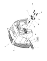
Figure 1 is a perspective view of an engine with the invention applied thereto. -
Figure 2 is a portion of the same view, from the front. -
Figure 3 is the same view in an exploded view. -
Figure 4 is a section of the main part of the invention, taken along the axis of the command cable. -
Figure 5 is section V-V offigure 2 . -
Figure 6 is section VI-VI offigure 2 . - The figures show that the
engine 1 contained in thecasing 2, in which the carburettor butterfly valve (not illustrated) is activated by thesheathed cable 3 comprising thecommand cable 31 contained in and slidable in thesheath 32. - The
cable 3 is brought up to the command lever, not illustrated, internally of acorrugated protection tube 4 in which thesmall cables 41 destined to earth the ignition for stopping the engine also run (figure 4 ). - The end of the
sheath 32 and thetube 4 are fixed to the engine casing between afirst portion 5 integrated into thecasing 2 and asecond portion 6 fixed to theportion 5 by means of threescrews - The two
portions corrugated tube 4. - Each of the
portions semi-cylindrical cavity screws tube 4 is blocked by tightening thescrews - The
cable 3 extends beyond the end of the tube 4 (figure 4 ) up to reaching in proximity of the commanded organ (not illustrated), to which thewire 31 is tensioned and fixed, by known means which are not illustrated. - The
sheath 32 of thewire 31 is maintained in position resting on ashelf 52 fashioned on theportion 5, and between twoshelves portion 5. - The
sheath 32 passes between theshelf 52 and theshelves roller 55 which is knurled on a surface thereof and which frictionally engages thesheath 32. - The
roller 55 is supported and guided into a hole in theportion 6, and projects externally thereof with a head provided with torsional engaging means, which means can be engaged by a screw-driver. - The
portion 6 also comprises ashelf 64 which projects towards theportion 5 in order to come into contact with thesheath 32 such as to lock it in position (seefigure 5 ). - The lock is effected by tightening the
screw 63 and is made possible by the fact that at the position of thescrew 63 theportion 6 is distanced from theportion 5 by a quantity which is such as to make it possible to lock the sheath 32 (seefigure 6 ). - When the
portion 6 is positioned against theportion 5, before tightening thescrews shelf 64 rests against thesheath 32, and a degree ofplay 100 is left between the two portions in proximity of thescrews play 200 left in proximity of the screw 63 (seefigure 6 ). - The invention functions as follows.
- The operator places the
corrugated tube 4 in thesemi-cylindrical cavity 50 and arranges thesheath 32 which projects from the tube onto theshelf 52 and between theshelves knurled roller 55. - At this point the operator places the
portion 6 in contact with theportion 5, with theshelf 64 in non-tightened contact with thesheath 32, a small play around thescrews screw 63. - The operator then proceeds to tighten the
screws corrugated tube 4 in position. - The operator then proceeds to activate the
roller 55, tensioning thesheath 32. - Once the
sheath 32 has been placed under tension, the operator proceeds to tighten thescrew 63, blocking the sheath in position between theportion 5 and theshelf 64 of theportion 6. - The invention is not limited to the above-described example, and any variants and improvements thereto can be made without its forsaking the ambit of the following claims.
Claims (5)
- An adjustment and blocking system of an accelerator cable of an internal combustion engine of a portable work machine comprising the engine, a tubular frame joining the engine with the tool, and a handle located in proximity of the engine and gripped by an operator, the handle comprising a command lever of a commanded organ of the engine, the lever being connected to the commanded organ via a sheathed cable, near to the commanded organ the sheath of the sheathed cable being connected to the engine casing, and the cable being connected to the commanded organ, characterised in that the casing of the engine comprises connecting means for blocking the end of the sheath of the cable to the engine casing while adjusting its position with respect to the engine casing.
- The system of claim 1, characterised in that the connecting means comprise a first portion in form of a support shelf in a single piece with the engine casing and a second portion separate from the casing in form of a support shelf joined to the first portion the sheathed cable being comprised between the first and the second portion passes, the second portion being fixed to the first portion by means of one or more screws, of which at least a screw is located near the sheath on a side thereof distal of the commanded organ, and at least a screw located near the sheath on a side thereof proximal of the commanded organ.
- The system of claim 2, characterised in that the connecting means comprise a knurled roller, supported by the second portion with an end that is accessible from outside, which knurled roller is pressed against a terminal portion of the sheath in a tract thereof located between the first and the second portion.
- The system of claim 2, characterised in that a play is afforded between the second and the first portion before tightening the screws and in proximity of one or more screws located at sides of the sheath, which play is less than a play left in proximity of the other screw.
- The system of claim 2, characterised in that the first portion and the second portion comprise two semi-cylindrical seatings facing one another which seatings are located between the two screws at the sides of the sheath, and between which two semi-cylindrical seatings an end of a corrugated tube is blocked; the two semi-cylindrical seatings also being able to receive other electrical command wires.
Applications Claiming Priority (1)
| Application Number | Priority Date | Filing Date | Title |
|---|---|---|---|
| ITRE2010A000028A IT1399097B1 (en) | 2010-03-26 | 2010-03-26 | ACCELERATOR CABLE REGISTER DEVICE. |
Publications (2)
| Publication Number | Publication Date |
|---|---|
| EP2369157A1 true EP2369157A1 (en) | 2011-09-28 |
| EP2369157B1 EP2369157B1 (en) | 2012-12-12 |
Family
ID=43086050
Family Applications (1)
| Application Number | Title | Priority Date | Filing Date |
|---|---|---|---|
| EP20110151563 Active EP2369157B1 (en) | 2010-03-26 | 2011-01-20 | An adjustment and blocking system of an accelerator cable |
Country Status (2)
| Country | Link |
|---|---|
| EP (1) | EP2369157B1 (en) |
| IT (1) | IT1399097B1 (en) |
Citations (4)
| Publication number | Priority date | Publication date | Assignee | Title |
|---|---|---|---|---|
| US4294133A (en) * | 1979-09-24 | 1981-10-13 | Ford Motor Company | Bowden cable retainer and adjuster |
| US4898039A (en) * | 1986-11-14 | 1990-02-06 | Kioritz Corporation | Throttle lever holding device |
| US6552891B1 (en) * | 1999-08-23 | 2003-04-22 | Andreas Stilhl Ag & Co. | Portable handheld work apparatus |
| US20040040539A1 (en) * | 2000-11-15 | 2004-03-04 | Wolfgang Luithardt | Adjusting device for a throttle pull of an internal combustion engine |
-
2010
- 2010-03-26 IT ITRE2010A000028A patent/IT1399097B1/en active
-
2011
- 2011-01-20 EP EP20110151563 patent/EP2369157B1/en active Active
Patent Citations (4)
| Publication number | Priority date | Publication date | Assignee | Title |
|---|---|---|---|---|
| US4294133A (en) * | 1979-09-24 | 1981-10-13 | Ford Motor Company | Bowden cable retainer and adjuster |
| US4898039A (en) * | 1986-11-14 | 1990-02-06 | Kioritz Corporation | Throttle lever holding device |
| US6552891B1 (en) * | 1999-08-23 | 2003-04-22 | Andreas Stilhl Ag & Co. | Portable handheld work apparatus |
| US20040040539A1 (en) * | 2000-11-15 | 2004-03-04 | Wolfgang Luithardt | Adjusting device for a throttle pull of an internal combustion engine |
Also Published As
| Publication number | Publication date |
|---|---|
| IT1399097B1 (en) | 2013-04-05 |
| EP2369157B1 (en) | 2012-12-12 |
| ITRE20100028A1 (en) | 2011-09-27 |
Similar Documents
| Publication | Publication Date | Title |
|---|---|---|
| US12233525B2 (en) | Working apparatus having a tubular part and a cable arrangement, and assembly method | |
| CN101301749B (en) | Manually Controlled Work Implements | |
| US20170218631A1 (en) | Rebar tying tool | |
| US6997633B2 (en) | Coupling for split-boom power tool | |
| US20100071925A1 (en) | Hand-Held Power Tool | |
| US6769669B2 (en) | Pulling apparatus | |
| US7617809B2 (en) | Starting brake for a hedge clipper | |
| JP5358709B2 (en) | Hand-operated work machine | |
| US6938587B2 (en) | Hand held power tool | |
| US20150025319A1 (en) | Bending angle adjustment mechanism for endoscope and endoscope having the bending angle adjustment mechanism | |
| JPH09500786A (en) | Vibration Isolator for Portable Power Machine | |
| US8756754B2 (en) | Anti-vibration cantilevered handle for a blowing apparatus | |
| WO2020050385A1 (en) | Binding machine | |
| EP2369157B1 (en) | An adjustment and blocking system of an accelerator cable | |
| US10390493B2 (en) | Pole saw conversion device to extend an operable reach of a chain saw | |
| KR20160051768A (en) | Holding device for fastening a fuel distributor to a combustion engine | |
| KR100836364B1 (en) | Transmission cable assembly device of manual transmission | |
| KR20180105541A (en) | Clip device fixing wire for vehicle | |
| CN114714903B (en) | Vehicle pedal assembly structure | |
| KR20120002457U (en) | Injector Removing Device | |
| JP3069766B2 (en) | Endoscope hand operation structure | |
| KR100783431B1 (en) | Transmission cable adjust mechanism | |
| KR20180078771A (en) | Band cable cutting device | |
| GB2287007A (en) | Electric cable control arm for mower | |
| JP4745162B2 (en) | Optical termination box for branching |
Legal Events
| Date | Code | Title | Description |
|---|---|---|---|
| PUAI | Public reference made under article 153(3) epc to a published international application that has entered the european phase |
Free format text: ORIGINAL CODE: 0009012 |
|
| AK | Designated contracting states |
Kind code of ref document: A1 Designated state(s): AL AT BE BG CH CY CZ DE DK EE ES FI FR GB GR HR HU IE IS IT LI LT LU LV MC MK MT NL NO PL PT RO RS SE SI SK SM TR |
|
| AX | Request for extension of the european patent |
Extension state: BA ME |
|
| 17P | Request for examination filed |
Effective date: 20120221 |
|
| 17Q | First examination report despatched |
Effective date: 20120412 |
|
| GRAP | Despatch of communication of intention to grant a patent |
Free format text: ORIGINAL CODE: EPIDOSNIGR1 |
|
| GRAS | Grant fee paid |
Free format text: ORIGINAL CODE: EPIDOSNIGR3 |
|
| GRAA | (expected) grant |
Free format text: ORIGINAL CODE: 0009210 |
|
| AK | Designated contracting states |
Kind code of ref document: B1 Designated state(s): AL AT BE BG CH CY CZ DE DK EE ES FI FR GB GR HR HU IE IS IT LI LT LU LV MC MK MT NL NO PL PT RO RS SE SI SK SM TR |
|
| REG | Reference to a national code |
Ref country code: GB Ref legal event code: FG4D |
|
| REG | Reference to a national code |
Ref country code: CH Ref legal event code: EP |
|
| REG | Reference to a national code |
Ref country code: AT Ref legal event code: REF Ref document number: 588441 Country of ref document: AT Kind code of ref document: T Effective date: 20121215 |
|
| REG | Reference to a national code |
Ref country code: IE Ref legal event code: FG4D |
|
| REG | Reference to a national code |
Ref country code: DE Ref legal event code: R096 Ref document number: 602011000558 Country of ref document: DE Effective date: 20130207 |
|
| PG25 | Lapsed in a contracting state [announced via postgrant information from national office to epo] |
Ref country code: FI Free format text: LAPSE BECAUSE OF FAILURE TO SUBMIT A TRANSLATION OF THE DESCRIPTION OR TO PAY THE FEE WITHIN THE PRESCRIBED TIME-LIMIT Effective date: 20121212 Ref country code: SE Free format text: LAPSE BECAUSE OF FAILURE TO SUBMIT A TRANSLATION OF THE DESCRIPTION OR TO PAY THE FEE WITHIN THE PRESCRIBED TIME-LIMIT Effective date: 20121212 Ref country code: LT Free format text: LAPSE BECAUSE OF FAILURE TO SUBMIT A TRANSLATION OF THE DESCRIPTION OR TO PAY THE FEE WITHIN THE PRESCRIBED TIME-LIMIT Effective date: 20121212 Ref country code: ES Free format text: LAPSE BECAUSE OF FAILURE TO SUBMIT A TRANSLATION OF THE DESCRIPTION OR TO PAY THE FEE WITHIN THE PRESCRIBED TIME-LIMIT Effective date: 20130323 Ref country code: NO Free format text: LAPSE BECAUSE OF FAILURE TO SUBMIT A TRANSLATION OF THE DESCRIPTION OR TO PAY THE FEE WITHIN THE PRESCRIBED TIME-LIMIT Effective date: 20130312 |
|
| REG | Reference to a national code |
Ref country code: NL Ref legal event code: VDEP Effective date: 20121212 |
|
| REG | Reference to a national code |
Ref country code: AT Ref legal event code: MK05 Ref document number: 588441 Country of ref document: AT Kind code of ref document: T Effective date: 20121212 |
|
| REG | Reference to a national code |
Ref country code: LT Ref legal event code: MG4D |
|
| PG25 | Lapsed in a contracting state [announced via postgrant information from national office to epo] |
Ref country code: SI Free format text: LAPSE BECAUSE OF FAILURE TO SUBMIT A TRANSLATION OF THE DESCRIPTION OR TO PAY THE FEE WITHIN THE PRESCRIBED TIME-LIMIT Effective date: 20121212 Ref country code: GR Free format text: LAPSE BECAUSE OF FAILURE TO SUBMIT A TRANSLATION OF THE DESCRIPTION OR TO PAY THE FEE WITHIN THE PRESCRIBED TIME-LIMIT Effective date: 20130313 Ref country code: LV Free format text: LAPSE BECAUSE OF FAILURE TO SUBMIT A TRANSLATION OF THE DESCRIPTION OR TO PAY THE FEE WITHIN THE PRESCRIBED TIME-LIMIT Effective date: 20121212 |
|
| PG25 | Lapsed in a contracting state [announced via postgrant information from national office to epo] |
Ref country code: BG Free format text: LAPSE BECAUSE OF FAILURE TO SUBMIT A TRANSLATION OF THE DESCRIPTION OR TO PAY THE FEE WITHIN THE PRESCRIBED TIME-LIMIT Effective date: 20130312 Ref country code: SK Free format text: LAPSE BECAUSE OF FAILURE TO SUBMIT A TRANSLATION OF THE DESCRIPTION OR TO PAY THE FEE WITHIN THE PRESCRIBED TIME-LIMIT Effective date: 20121212 Ref country code: EE Free format text: LAPSE BECAUSE OF FAILURE TO SUBMIT A TRANSLATION OF THE DESCRIPTION OR TO PAY THE FEE WITHIN THE PRESCRIBED TIME-LIMIT Effective date: 20121212 Ref country code: BE Free format text: LAPSE BECAUSE OF FAILURE TO SUBMIT A TRANSLATION OF THE DESCRIPTION OR TO PAY THE FEE WITHIN THE PRESCRIBED TIME-LIMIT Effective date: 20121212 Ref country code: IS Free format text: LAPSE BECAUSE OF FAILURE TO SUBMIT A TRANSLATION OF THE DESCRIPTION OR TO PAY THE FEE WITHIN THE PRESCRIBED TIME-LIMIT Effective date: 20130412 Ref country code: RS Free format text: LAPSE BECAUSE OF FAILURE TO SUBMIT A TRANSLATION OF THE DESCRIPTION OR TO PAY THE FEE WITHIN THE PRESCRIBED TIME-LIMIT Effective date: 20121212 Ref country code: CZ Free format text: LAPSE BECAUSE OF FAILURE TO SUBMIT A TRANSLATION OF THE DESCRIPTION OR TO PAY THE FEE WITHIN THE PRESCRIBED TIME-LIMIT Effective date: 20121212 Ref country code: AT Free format text: LAPSE BECAUSE OF FAILURE TO SUBMIT A TRANSLATION OF THE DESCRIPTION OR TO PAY THE FEE WITHIN THE PRESCRIBED TIME-LIMIT Effective date: 20121212 |
|
| PG25 | Lapsed in a contracting state [announced via postgrant information from national office to epo] |
Ref country code: PT Free format text: LAPSE BECAUSE OF FAILURE TO SUBMIT A TRANSLATION OF THE DESCRIPTION OR TO PAY THE FEE WITHIN THE PRESCRIBED TIME-LIMIT Effective date: 20130412 Ref country code: NL Free format text: LAPSE BECAUSE OF FAILURE TO SUBMIT A TRANSLATION OF THE DESCRIPTION OR TO PAY THE FEE WITHIN THE PRESCRIBED TIME-LIMIT Effective date: 20121212 Ref country code: MC Free format text: LAPSE BECAUSE OF NON-PAYMENT OF DUE FEES Effective date: 20130131 Ref country code: RO Free format text: LAPSE BECAUSE OF FAILURE TO SUBMIT A TRANSLATION OF THE DESCRIPTION OR TO PAY THE FEE WITHIN THE PRESCRIBED TIME-LIMIT Effective date: 20121212 Ref country code: PL Free format text: LAPSE BECAUSE OF FAILURE TO SUBMIT A TRANSLATION OF THE DESCRIPTION OR TO PAY THE FEE WITHIN THE PRESCRIBED TIME-LIMIT Effective date: 20121212 |
|
| PLBE | No opposition filed within time limit |
Free format text: ORIGINAL CODE: 0009261 |
|
| STAA | Information on the status of an ep patent application or granted ep patent |
Free format text: STATUS: NO OPPOSITION FILED WITHIN TIME LIMIT |
|
| REG | Reference to a national code |
Ref country code: IE Ref legal event code: MM4A |
|
| PG25 | Lapsed in a contracting state [announced via postgrant information from national office to epo] |
Ref country code: DK Free format text: LAPSE BECAUSE OF FAILURE TO SUBMIT A TRANSLATION OF THE DESCRIPTION OR TO PAY THE FEE WITHIN THE PRESCRIBED TIME-LIMIT Effective date: 20121212 |
|
| 26N | No opposition filed |
Effective date: 20130913 |
|
| PG25 | Lapsed in a contracting state [announced via postgrant information from national office to epo] |
Ref country code: CY Free format text: LAPSE BECAUSE OF FAILURE TO SUBMIT A TRANSLATION OF THE DESCRIPTION OR TO PAY THE FEE WITHIN THE PRESCRIBED TIME-LIMIT Effective date: 20121212 Ref country code: HR Free format text: LAPSE BECAUSE OF FAILURE TO SUBMIT A TRANSLATION OF THE DESCRIPTION OR TO PAY THE FEE WITHIN THE PRESCRIBED TIME-LIMIT Effective date: 20121212 |
|
| REG | Reference to a national code |
Ref country code: DE Ref legal event code: R097 Ref document number: 602011000558 Country of ref document: DE Effective date: 20130913 |
|
| PG25 | Lapsed in a contracting state [announced via postgrant information from national office to epo] |
Ref country code: IE Free format text: LAPSE BECAUSE OF NON-PAYMENT OF DUE FEES Effective date: 20130120 Ref country code: AL Free format text: LAPSE BECAUSE OF FAILURE TO SUBMIT A TRANSLATION OF THE DESCRIPTION OR TO PAY THE FEE WITHIN THE PRESCRIBED TIME-LIMIT Effective date: 20121212 |
|
| PG25 | Lapsed in a contracting state [announced via postgrant information from national office to epo] |
Ref country code: MT Free format text: LAPSE BECAUSE OF FAILURE TO SUBMIT A TRANSLATION OF THE DESCRIPTION OR TO PAY THE FEE WITHIN THE PRESCRIBED TIME-LIMIT Effective date: 20121212 |
|
| REG | Reference to a national code |
Ref country code: CH Ref legal event code: PL |
|
| PG25 | Lapsed in a contracting state [announced via postgrant information from national office to epo] |
Ref country code: LI Free format text: LAPSE BECAUSE OF NON-PAYMENT OF DUE FEES Effective date: 20140131 Ref country code: CH Free format text: LAPSE BECAUSE OF NON-PAYMENT OF DUE FEES Effective date: 20140131 |
|
| PG25 | Lapsed in a contracting state [announced via postgrant information from national office to epo] |
Ref country code: SM Free format text: LAPSE BECAUSE OF FAILURE TO SUBMIT A TRANSLATION OF THE DESCRIPTION OR TO PAY THE FEE WITHIN THE PRESCRIBED TIME-LIMIT Effective date: 20121212 |
|
| PG25 | Lapsed in a contracting state [announced via postgrant information from national office to epo] |
Ref country code: TR Free format text: LAPSE BECAUSE OF FAILURE TO SUBMIT A TRANSLATION OF THE DESCRIPTION OR TO PAY THE FEE WITHIN THE PRESCRIBED TIME-LIMIT Effective date: 20121212 |
|
| PG25 | Lapsed in a contracting state [announced via postgrant information from national office to epo] |
Ref country code: HU Free format text: LAPSE BECAUSE OF FAILURE TO SUBMIT A TRANSLATION OF THE DESCRIPTION OR TO PAY THE FEE WITHIN THE PRESCRIBED TIME-LIMIT; INVALID AB INITIO Effective date: 20110120 Ref country code: LU Free format text: LAPSE BECAUSE OF NON-PAYMENT OF DUE FEES Effective date: 20130120 Ref country code: MK Free format text: LAPSE BECAUSE OF FAILURE TO SUBMIT A TRANSLATION OF THE DESCRIPTION OR TO PAY THE FEE WITHIN THE PRESCRIBED TIME-LIMIT Effective date: 20121212 |
|
| GBPC | Gb: european patent ceased through non-payment of renewal fee |
Effective date: 20150120 |
|
| PG25 | Lapsed in a contracting state [announced via postgrant information from national office to epo] |
Ref country code: GB Free format text: LAPSE BECAUSE OF NON-PAYMENT OF DUE FEES Effective date: 20150120 |
|
| REG | Reference to a national code |
Ref country code: FR Ref legal event code: PLFP Year of fee payment: 6 |
|
| REG | Reference to a national code |
Ref country code: FR Ref legal event code: PLFP Year of fee payment: 7 |
|
| REG | Reference to a national code |
Ref country code: FR Ref legal event code: PLFP Year of fee payment: 8 |
|
| P01 | Opt-out of the competence of the unified patent court (upc) registered |
Effective date: 20230605 |
|
| PGFP | Annual fee paid to national office [announced via postgrant information from national office to epo] |
Ref country code: DE Payment date: 20260128 Year of fee payment: 16 |
|
| PGFP | Annual fee paid to national office [announced via postgrant information from national office to epo] |
Ref country code: IT Payment date: 20251128 Year of fee payment: 16 |
|
| PGFP | Annual fee paid to national office [announced via postgrant information from national office to epo] |
Ref country code: FR Payment date: 20260126 Year of fee payment: 16 |