EP2369156A2 - System and method for cooling gas turbine components - Google Patents
System and method for cooling gas turbine components Download PDFInfo
- Publication number
- EP2369156A2 EP2369156A2 EP11159016A EP11159016A EP2369156A2 EP 2369156 A2 EP2369156 A2 EP 2369156A2 EP 11159016 A EP11159016 A EP 11159016A EP 11159016 A EP11159016 A EP 11159016A EP 2369156 A2 EP2369156 A2 EP 2369156A2
- Authority
- EP
- European Patent Office
- Prior art keywords
- turbine
- carbon dioxide
- gas
- dioxide gas
- cooling
- Prior art date
- Legal status (The legal status is an assumption and is not a legal conclusion. Google has not performed a legal analysis and makes no representation as to the accuracy of the status listed.)
- Withdrawn
Links
- 238000000034 method Methods 0.000 title claims description 47
- 239000000112 cooling gas Substances 0.000 title 1
- CURLTUGMZLYLDI-UHFFFAOYSA-N Carbon dioxide Chemical compound O=C=O CURLTUGMZLYLDI-UHFFFAOYSA-N 0.000 claims abstract description 210
- 229910002092 carbon dioxide Inorganic materials 0.000 claims abstract description 139
- 239000001569 carbon dioxide Substances 0.000 claims abstract description 139
- 238000001816 cooling Methods 0.000 claims abstract description 63
- 239000012530 fluid Substances 0.000 claims abstract description 35
- 230000015572 biosynthetic process Effects 0.000 claims abstract description 31
- 238000003786 synthesis reaction Methods 0.000 claims abstract description 31
- 238000004891 communication Methods 0.000 claims abstract description 27
- 238000002309 gasification Methods 0.000 claims abstract description 27
- 239000000446 fuel Substances 0.000 claims abstract description 26
- 239000007789 gas Substances 0.000 claims description 186
- 239000002253 acid Substances 0.000 claims description 34
- 239000002904 solvent Substances 0.000 claims description 27
- 238000010248 power generation Methods 0.000 claims description 18
- 238000003860 storage Methods 0.000 claims description 18
- 230000008569 process Effects 0.000 claims description 10
- 239000003085 diluting agent Substances 0.000 claims description 9
- 238000012546 transfer Methods 0.000 claims description 4
- 239000004215 Carbon black (E152) Substances 0.000 abstract description 3
- 229930195733 hydrocarbon Natural products 0.000 abstract description 3
- 150000002430 hydrocarbons Chemical class 0.000 abstract description 3
- 230000006835 compression Effects 0.000 description 10
- 238000007906 compression Methods 0.000 description 10
- RWSOTUBLDIXVET-UHFFFAOYSA-N Dihydrogen sulfide Chemical compound S RWSOTUBLDIXVET-UHFFFAOYSA-N 0.000 description 8
- 238000002485 combustion reaction Methods 0.000 description 8
- IJGRMHOSHXDMSA-UHFFFAOYSA-N Atomic nitrogen Chemical compound N#N IJGRMHOSHXDMSA-UHFFFAOYSA-N 0.000 description 6
- UGFAIRIUMAVXCW-UHFFFAOYSA-N Carbon monoxide Chemical compound [O+]#[C-] UGFAIRIUMAVXCW-UHFFFAOYSA-N 0.000 description 5
- 230000007246 mechanism Effects 0.000 description 5
- 230000009919 sequestration Effects 0.000 description 5
- 229910002091 carbon monoxide Inorganic materials 0.000 description 4
- 238000004140 cleaning Methods 0.000 description 4
- 239000000203 mixture Substances 0.000 description 4
- 238000011084 recovery Methods 0.000 description 4
- 238000006722 reduction reaction Methods 0.000 description 4
- 230000001172 regenerating effect Effects 0.000 description 4
- XLYOFNOQVPJJNP-UHFFFAOYSA-N water Chemical compound O XLYOFNOQVPJJNP-UHFFFAOYSA-N 0.000 description 4
- 238000010586 diagram Methods 0.000 description 3
- 229910052757 nitrogen Inorganic materials 0.000 description 3
- 230000009467 reduction Effects 0.000 description 3
- 239000002028 Biomass Substances 0.000 description 2
- NINIDFKCEFEMDL-UHFFFAOYSA-N Sulfur Chemical compound [S] NINIDFKCEFEMDL-UHFFFAOYSA-N 0.000 description 2
- 239000005864 Sulphur Substances 0.000 description 2
- QVGXLLKOCUKJST-UHFFFAOYSA-N atomic oxygen Chemical compound [O] QVGXLLKOCUKJST-UHFFFAOYSA-N 0.000 description 2
- 229940105305 carbon monoxide Drugs 0.000 description 2
- 239000003245 coal Substances 0.000 description 2
- 239000002826 coolant Substances 0.000 description 2
- 230000000694 effects Effects 0.000 description 2
- 239000007788 liquid Substances 0.000 description 2
- 239000001301 oxygen Substances 0.000 description 2
- 229910052760 oxygen Inorganic materials 0.000 description 2
- 239000003208 petroleum Substances 0.000 description 2
- 238000005201 scrubbing Methods 0.000 description 2
- OKTJSMMVPCPJKN-UHFFFAOYSA-N Carbon Chemical compound [C] OKTJSMMVPCPJKN-UHFFFAOYSA-N 0.000 description 1
- MYMOFIZGZYHOMD-UHFFFAOYSA-N Dioxygen Chemical compound O=O MYMOFIZGZYHOMD-UHFFFAOYSA-N 0.000 description 1
- 239000006096 absorbing agent Substances 0.000 description 1
- 230000004075 alteration Effects 0.000 description 1
- 238000004458 analytical method Methods 0.000 description 1
- 230000005540 biological transmission Effects 0.000 description 1
- 239000006227 byproduct Substances 0.000 description 1
- 229910052799 carbon Inorganic materials 0.000 description 1
- 239000000567 combustion gas Substances 0.000 description 1
- 239000000356 contaminant Substances 0.000 description 1
- 238000007796 conventional method Methods 0.000 description 1
- 238000007865 diluting Methods 0.000 description 1
- 238000010790 dilution Methods 0.000 description 1
- 239000012895 dilution Substances 0.000 description 1
- 230000005611 electricity Effects 0.000 description 1
- 238000005516 engineering process Methods 0.000 description 1
- 238000000605 extraction Methods 0.000 description 1
- 238000010304 firing Methods 0.000 description 1
- 239000003546 flue gas Substances 0.000 description 1
- 238000010438 heat treatment Methods 0.000 description 1
- 239000001257 hydrogen Substances 0.000 description 1
- 229910052739 hydrogen Inorganic materials 0.000 description 1
- 125000004435 hydrogen atom Chemical class [H]* 0.000 description 1
- 238000004519 manufacturing process Methods 0.000 description 1
- 239000012528 membrane Substances 0.000 description 1
- 238000002156 mixing Methods 0.000 description 1
- 238000012545 processing Methods 0.000 description 1
- 238000004064 recycling Methods 0.000 description 1
- 238000000926 separation method Methods 0.000 description 1
- 238000006467 substitution reaction Methods 0.000 description 1
- 238000011144 upstream manufacturing Methods 0.000 description 1
Images


Classifications
-
- F—MECHANICAL ENGINEERING; LIGHTING; HEATING; WEAPONS; BLASTING
- F02—COMBUSTION ENGINES; HOT-GAS OR COMBUSTION-PRODUCT ENGINE PLANTS
- F02C—GAS-TURBINE PLANTS; AIR INTAKES FOR JET-PROPULSION PLANTS; CONTROLLING FUEL SUPPLY IN AIR-BREATHING JET-PROPULSION PLANTS
- F02C7/00—Features, components parts, details or accessories, not provided for in, or of interest apart form groups F02C1/00 - F02C6/00; Air intakes for jet-propulsion plants
- F02C7/12—Cooling of plants
- F02C7/16—Cooling of plants characterised by cooling medium
- F02C7/18—Cooling of plants characterised by cooling medium the medium being gaseous, e.g. air
-
- Y—GENERAL TAGGING OF NEW TECHNOLOGICAL DEVELOPMENTS; GENERAL TAGGING OF CROSS-SECTIONAL TECHNOLOGIES SPANNING OVER SEVERAL SECTIONS OF THE IPC; TECHNICAL SUBJECTS COVERED BY FORMER USPC CROSS-REFERENCE ART COLLECTIONS [XRACs] AND DIGESTS
- Y02—TECHNOLOGIES OR APPLICATIONS FOR MITIGATION OR ADAPTATION AGAINST CLIMATE CHANGE
- Y02E—REDUCTION OF GREENHOUSE GAS [GHG] EMISSIONS, RELATED TO ENERGY GENERATION, TRANSMISSION OR DISTRIBUTION
- Y02E20/00—Combustion technologies with mitigation potential
- Y02E20/16—Combined cycle power plant [CCPP], or combined cycle gas turbine [CCGT]
- Y02E20/18—Integrated gasification combined cycle [IGCC], e.g. combined with carbon capture and storage [CCS]
Definitions
- the subject matter disclosed herein relates to gas turbines and, more particularly, to cooling mechanisms in gas turbines.
- IGCC Integrated Gasification Combined Cycle
- IGCC uses a gasification process to produce synthesis gas (syngas) from fuel sources such as coal, heavy petroleum residues, biomass and others.
- the syngas is used as a fuel in gas turbines for producing electricity.
- IGCC systems can be advantageous in reducing carbon dioxide (CO 2 ) emissions through mechanisms such as pre-combustion carbon capture.
- IGCC power plants adopt pre-combustion systems for CO 2 capture.
- the capture of CO 2 from IGCC plants penalizes the performance of such plants, particularly in production output and efficiency.
- cooling of the stationary and rotating components of a gas turbines by the conventional method of extracting air from the turbine's compressor reduces turbine efficiency by, for example, reducing the Brayton cycle efficiency.
- This loss of efficiency is manifested due to factors such as reduction in firing temperatures due to non-chargeable flow diluting the combustor exit temperature, reduction in work on account of bypassing compressed air at upstream stages of the turbine, and reduction in work potential on account of dilution effects of the coolant stream mixing in the main gas path and the associated loss of aerodynamic efficiency.
- a system for cooling components of a turbine includes: at least one input in fluid communication with a source of carbon dioxide gas, the carbon dioxide gas removed from synthesis gas produced by a gasification unit from hydrocarbon fuel; and at least one first conduit in fluid communication with the at least one input and configured to divert a portion of the carbon dioxide gas from the source of carbon dioxide gas to at least one component of the turbine, the turbine configured to combust the synthesis gas.
- a system for power generation includes: a gasification unit configured to produce raw synthesis gas from an input fuel; an acid gas removal plant in fluid communication with the gasification unit, the acid gas removal plant configured to remove acid gas from the raw synthesis gas and produce clean synthesis gas, the acid gas including carbon dioxide gas; a gas turbine configured to combust the clean sythensis gas; and a cooling unit in fluid communication with the acid gas removal plant and configured to divert at least a portion of the carbon dioxide gas to at least one component of a gas turbine.
- a method of cooling components of a turbine includes: extracting carbon dioxide gas from a synthesis gas produced by a gasification process; advancing the carbon dioxide gas to a storage system; and diverting a portion of the carbon dioxide gas to the turbine to cool at least one component of the turbine.
- An exemplary turbine systems include integrated gasification combined cycle (IGCC) power generation systems.
- the systems and method are utilized in conjunction with IGCC or other turbine systems that incorporate pre-combustion systems for carbon dioxide (CO 2 ) capture.
- IGCC integrated gasification combined cycle
- Exemplary systems and methods include cooling turbines using CO 2 captured by a power generation and/or CO 2 removal system.
- Exemplary systems and methods utilize captured CO 2 as cooling media for cooling of stationary and/or rotating components of turbines, such as gas turbines, in a closed loop cooling scheme.
- the systems and method include utilizing a synthesis gas cleaning solvent or other fluid that is available in sythesis gas cleaning systems, CO 2 removal systems and/or power plants such as IGCC plants.
- the solvents are enabled to capture CO 2 from turbine fuel produced by gasification, which are utilized by the systems and methods described herein for turbine cooling.
- a gas turbine assembly constructed in accordance with an exemplary embodiment of the invention is indicated generally at 10.
- the assembly 10 includes a rotor 12 attached to a compressor 14 and a power turbine 16.
- a combustion chamber 18 is in fluid communication with both the compressor 14 and the power turbine 16, and acts to ignite a fuel and air mixture to cause rotation of the power turbine 16 and the rotor 12.
- Rotation of the rotor 12 in turn powers, for example, a generator 20.
- Exhaust gas 22 is exhausted from the power turbine 16.
- at least a portion of the exhaust gas 22 is guided to a heat recovery steam generator (HRSG) that recovers heat from the hot exhaust gas 22 and produces steam that is usable in, for example, a steam turbine in an electrical generation system.
- HRSG heat recovery steam generator
- the turbine includes various internal components that are exposed to elevated temperatures during operation of the turbine assembly 10.
- Such components include a rotor shaft and rotor disks that rotate about a central axis.
- Exemplary components also include rotating components 24 such as blades or buckets, which can be removably attached to an outer periphery of each rotor disk.
- Other components include stationary components 26 such as stator vanes or nozzles.
- an IGCC power generation plant 30 is shown.
- One or more fuels such as coal or other hydrocarbon fuels, petroleum residues and biomass are fed into a gasification and scrubbing unit 32 in which the fuel undergoes a reduction reaction and synthesis gas (“syngas”), a mixture of primarily carbon monoxide (CO) and hydrogen, is produced.
- the raw syngas may be cooled via, for example, a radiant syngas cooler and/or a low temperature gas cooling (LTGC) system 36.
- LTGC low temperature gas cooling
- the combustion chamber 18, or other suitable equipment is utilized in an oxyfuel cycle.
- Oxyfuel cycles generally include the combustion of fuel with pure oxygen, in place of air.
- oxyfuel includes an oxygen enriched gas mixture diluted with combustion gas such as gas turbine exhaust (i.e., flue gas consisting mostly of CO 2 and H 2 O).
- the gases are advanced into a two stage shift reactor 34 in which water vapor is used to convert the CO into carbon dioxide (CO 2 ).
- the syngas is only a raw syngas that includes acid gases, which include various contaminants such as CO 2 and hydrogen sulphide (H 2 S).
- acid gases which include various contaminants such as CO 2 and hydrogen sulphide (H 2 S).
- H 2 S hydrogen sulphide
- Various other gases are also produced in the gasification process, and present in the syngas, such as nitrogen, carbon mon-oxide, and others.
- An acid gas removal (AGR) plant 42 then receives the raw syngas.
- the AGR plant 42 processes the raw syngas to remove H 2 S, which can be sent to a tail gas treatment unit (TGTU) 40, and CO 2 from the raw syngas.
- the AGR plant 42 includes, for example, an absorber in which a solvent absorbs H 2 S and CO 2 from the raw syngas to produce a "sweetened" or clean syngas.
- An example of a suitable solvent is Selexol TM (Union Carbide Corporation), although any solvent capable of removing acid gases from a gas mixture may be used.
- the AGR plant 42 may use any suitable process for sweetening the syngas. Examples of such sweetening processes include selective gas removal processes such as the utilization of CO 2 and H 2 S selective membranes, warm sulphur removal technologies and others.
- the solvent includes concentrations of H 2 S and CO 2 and may be refered to as a "rich" solvent.
- the rich solvent is fed into one or more regenerators (including, for example, a stripper and boiler) in which the H 2 S and CO2 are stripped from the solvent, resulting in a "lean” solvent.
- the lean solvent can be recycled for use in subsequent acid gas removal operations.
- the removed CO 2 is advanced through, for example, an Integrated CO2 Enrichment system 44, and sent to a compression and/or storage unit 46 for CO2 capture and/or enhanced oil recovery.
- a portion of the CO 2 in one embodiment, is diverted via a recycling/compression system 38 and directed back into the gasification unit 32.
- the TGTU 40 may be used to remove sulphur from the raw syngas.
- the clean syngas is then advanced through various saturation and heating systems 48 and fed into a combined cycle power block 50 for power generation.
- the power block 50 includes a gas turbine such as the gas turbine assembly 10 and may also include a steam turbine for producing energy from the gas turbine exhaust gases.
- the IGCC plant 30 includes an air separation unit (ASU) 52.
- Air can be diverted from the gas turbine compressor and fed into the ASU 52.
- the ASU 52 separates oxygen from the air that can be fed into the gasification unit 32, and also produces nitrogen, which can be diverted back to the turbine for cooling.
- a portion of the CO 2 at a suitable pressure is extracted from the CO 2 removal system and diverted to the power block 50 to cool the gas turbine stationary or rotating components in a closed loop system wherein the heat picked up by CO 2 is recovered.
- the CO 2 is diverted to the gas turbine via any suitable cooling system 54.
- the cooling system 54, the combined cycle power block 50 and/or the IGCC power plant 30 includes one ore more heat exchangers to regenerate thermal energy from the CO2 that has been heated as a result of applying the CO 2 to the gas turbine.
- the heat exchanges are configured to heat components such as the fuel and/or diluent stream entering the gas turbine, the steam turbine, as well as any other desired fluids such as boiler fluids.
- the CO 2 After the CO 2 is applied to the gas turbine and/or the steam turbine, and any additional components, it may be subsequently sent to the compression and/or storage system 46, where the CO 2 is compressed to a selected pressure, such as 2000psig ( ⁇ 140 bars), a typical pressure to supply liquid CO 2 for Enhanced Oil Recovery (EOR) applications.
- a selected pressure such as 2000psig ( ⁇ 140 bars), a typical pressure to supply liquid CO 2 for Enhanced Oil Recovery (EOR) applications.
- a cooling system 60 is incorporated into a gas turbine system that utilizes CO 2 removal and/or capture.
- the cooling system 60 includes one or more conduits 62 or other mechanisms for applying CO 2 to various components of a gas turbine 64.
- the cooling system 60 also includes, in one embodiment, a gas turbine cooling CO 2 controller 66 that includes processors, memory, transmission devices and/or displays suitable for controlling the operation of the cooling system 60 as well as receiving, processing, displaying and/or transmitting information regarding the cooling system 60.
- the cooling system 60 is in operable communication with the gas turbine 64 and a portion of the AGR plant 42.
- the AGR plant 42 includes one or more flash tanks 68 that separate CO 2 from a rich solvent.
- Gas conduits 69 are configured to route the separated CO 2 from the flash tanks 68 to desired locations, such as the compression and/or storage unit 46.
- CO 2 fluid from a H 2 S reabsorber 67 is routed to the gas turbine cooling CO 2 controller 66.
- the cooling system conduits 62 are in fluid communication with respective gas conduits 69 to divert a portion of the separated CO 2 into the cooling system 60.
- the flow of CO 2 into the cooling system can be controlled by the controller 66.
- the cooling system 60 include valves 70 for controlling the flow of CO 2 from the gas conduits 69, through the cooling system 60 and into the gas turbine 64.
- the valves 70 may be selectively operated via, for example, the controller 66.
- the cooling system 60 in one embodiment, is a closed loop system.
- CO 2 gas is flowed from the cooling system 60 into selected turbine stages, such as a power turbine stage 72, and is directed to selected moving and/or stationary components.
- the CO 2 absorbs heat from the components, and the heated CO 2 may be fed through a fuel line heat exchanger 74 and a diluent line heat exchanger 76 to heat fuel and diluent being fed into the turbine's combustion chamber 78.
- the CO 2 continues on to at least one additional heat exchanger 80 to heat exhaust gases used in steam generation and trim cooling, before it is returned to one or more of the gas conduits 68 and/or a CO 2 storage system.
- the cooling system 60 in this embodiment is configured to communicate with an indirect cooling unit (ICU).
- ICU indirect cooling unit
- the ICU defines the closed loop cooling of turbine components.
- CO 2 fluid from the ICU is routed to heat exchangers (e.g, air-fluid heat exchanger, fluid-fuel heat exchanger, heat sinks, regenerative heat exchanger) and it is returned to the CO 2 compression and sequestration unit 90.
- heat exchangers e.g, air-fluid heat exchanger, fluid-fuel heat exchanger, heat sinks, regenerative heat exchanger
- CO 2 fluid from the ICU is fed to heat exchangers 82 that are configured to transfer heat from the bleed CO 2 to fluids such as the fuel, diluent, compressor discharge air and/or boiler feed water (BFW). Further heat is transferred back to the CO 2 which is entering ICU through a regenerative heat exchanger system 84.
- CO 2 fluid can also be cooled through optional low temperature heat exchange systems 94 (e.g., trim coolers, other areas of steam heat exchangers and others) that further cool the CO 2 to facilitate compression, liquefication and/or sequestration.
- optional low temperature heat exchange systems 94 e.g., trim coolers, other areas of steam heat exchangers and others
- the cooling system 60 is in fluid communication with a CO 2 capture, recovery and sequestration system 86.
- the CO 2 capture unit includes a number of capture modules 88. Exemplary capture modules include flash tanks 68 which through which rich solvent is passed.
- the capture modules 88 can include high pressure (HP), medium pressure (MP) and/or low pressure (LP) modules 88 in fluid communication with a CO 2 compression and sequestration unit 90.
- a portion of the CO 2 from capture modules 88 may be diverted through an optional gas compression system 92 through regenerative heat exchangers 84 to selected ICU of turbine components.
- FIG. 5 illustrates a method 100 of cooling components of a turbine.
- the method 100 includes one or more stages 101-104. Although the method 100 is described in conjunction with the IGCC power plant 30 and the cooling system 60, the method 100 may be used with any system capable of cooling a turbine assembly as described herein. In one embodiment, the method 100 includes the execution of all of stages 101-104 in the order described. However, certain stages may be omitted, stages may be added, or the order of the stages changed.
- fuel is flowed into a gasification system such as the gasification and scrubbing unit 32 and raw syngas is produced.
- the raw syngas is cleaned or sweetened by a suitable cleaning system such as the AGR plant 42 to remove acid gases from the raw syngas.
- CO 2 gas is extracted from the raw syngas and/or from byproducts of cleaning the raw syngas.
- CO 2 gas is removed from a solvent used to clean the raw syngas by the flash tanks 68 or other CO 2 extraction mechanisms.
- the CO 2 gas is advanced to a CO 2 capture and/or storage system, such as the compression and/or storage unit 46.
- a portion of the CO 2 gas is diverted to a cooling system such as the cooling system 60 that applies the CO 2 gas portion to selected components of a turbine such as a gas turbine.
- exemplary components include rotating blades or buckets and stationary components such as stator vanes.
- the CO 2 gas portion which has been heated by the turbine components, is recovered in thermal energy / regenerated and then returned to the CO 2 capture and/or storage system.
- the heated CO 2 gas portion is cooled and thermal energy is transferred to fuel, diluents and/or other components of a power generation system prior to returning the CO 2 gas portion to the CO 2 capture and/or storage system.
- the CO 2 gas portion is cooled by transferring thermal energy from the CO 2 gas portion to an indirect cooling unit by a suitable heat exchange mechanism such as the regenerative heat exchanger 84.
- any other suitable type of turbine may be used.
- the systems and methods described herein may be used with a steam turbine or turbine including both gas and steam generation.
- the systems and methods described herein may be utilized in conjunction with any of various turbine power generation systems, and are not limited to the specific power generation systems described herein.
- the systems and methods described herein may be utilized in place of or in addition to various other cooling systems.
- Examples of such cooling systems include closed loop systems using cooling media for hot gas path components such as steam, nitrogen and liquid (e.g., water) coolants.
- the devices, systems and methods described herein provide numerous advantages over prior art systems.
- the devices, systems and methods provide the technical effect of increasing efficiency and performance of the turbine.
- based on analyses of exemplary systems, systems and methods such as those described herein can improve output and efficiency, for example by improving net output by 14.5% and efficiency by 0.52 points over the baseline scenario that is practiced in the prior art.
Landscapes
- Engineering & Computer Science (AREA)
- Chemical & Material Sciences (AREA)
- Combustion & Propulsion (AREA)
- Mechanical Engineering (AREA)
- General Engineering & Computer Science (AREA)
- Engine Equipment That Uses Special Cycles (AREA)
- Industrial Gases (AREA)
Abstract
A system for cooling components of a turbine (16, 64) includes: at least one input in fluid communication with a source of carbon dioxide gas, the carbon dioxide gas removed from synthesis gas produced by a gasification unit (32) from hydrocarbon fuel; and at least one first conduit (62, 69) in fluid communication with the at least one input and configured to divert a portion of the carbon dioxide gas from the source of carbon dioxide gas to at least one component of the turbine (16), the turbine (16) configured to combust the synthesis gas.
Description
- The subject matter disclosed herein relates to gas turbines and, more particularly, to cooling mechanisms in gas turbines.
- Integrated Gasification Combined Cycle (IGCC) systems are increasingly being utilized for power generation. IGCC uses a gasification process to produce synthesis gas (syngas) from fuel sources such as coal, heavy petroleum residues, biomass and others. The syngas is used as a fuel in gas turbines for producing electricity. IGCC systems can be advantageous in reducing carbon dioxide (CO2) emissions through mechanisms such as pre-combustion carbon capture.
- IGCC power plants adopt pre-combustion systems for CO2 capture. Currently, the capture of CO2 from IGCC plants penalizes the performance of such plants, particularly in production output and efficiency. In addition, cooling of the stationary and rotating components of a gas turbines by the conventional method of extracting air from the turbine's compressor reduces turbine efficiency by, for example, reducing the Brayton cycle efficiency. This loss of efficiency is manifested due to factors such as reduction in firing temperatures due to non-chargeable flow diluting the combustor exit temperature, reduction in work on account of bypassing compressed air at upstream stages of the turbine, and reduction in work potential on account of dilution effects of the coolant stream mixing in the main gas path and the associated loss of aerodynamic efficiency.
- According to one aspect of the invention, a system for cooling components of a turbine includes: at least one input in fluid communication with a source of carbon dioxide gas, the carbon dioxide gas removed from synthesis gas produced by a gasification unit from hydrocarbon fuel; and at least one first conduit in fluid communication with the at least one input and configured to divert a portion of the carbon dioxide gas from the source of carbon dioxide gas to at least one component of the turbine, the turbine configured to combust the synthesis gas.
- According to another aspect of the invention, a system for power generation includes: a gasification unit configured to produce raw synthesis gas from an input fuel; an acid gas removal plant in fluid communication with the gasification unit, the acid gas removal plant configured to remove acid gas from the raw synthesis gas and produce clean synthesis gas, the acid gas including carbon dioxide gas; a gas turbine configured to combust the clean sythensis gas; and a cooling unit in fluid communication with the acid gas removal plant and configured to divert at least a portion of the carbon dioxide gas to at least one component of a gas turbine.
- According to yet another aspect of the invention, a method of cooling components of a turbine includes: extracting carbon dioxide gas from a synthesis gas produced by a gasification process; advancing the carbon dioxide gas to a storage system; and diverting a portion of the carbon dioxide gas to the turbine to cool at least one component of the turbine.
- These and other advantages and features will become more apparent from the following description taken in conjunction with the drawings.
- The subject matter, which is regarded as the invention, is particularly pointed out and distinctly claimed in the claims at the conclusion of the specification. The foregoing and other features, and advantages of the invention are apparent from the following detailed description taken in conjunction with the accompanying drawings in which:
-
FIG. 1 is a cross-sectional view of an exemplary gas turbine; -
FIG 2 is a block diagram of an exemplary Integrated Gasification Combined Cycle (IGCC) power plant with CO2 capture; -
FIG. 3 is a diagram of an exemplary gas turbine cooling system for use in the IGCC power plant ofFIG. 2 ; -
FIG. 4 is a diagram of an exemplary gas turbine cooling system for use in the IGCC power plant ofFIG. 2 ; and -
FIG. 5 is an exemplary method of cooling a gas turbine. - The detailed description explains embodiments of the invention, together with advantages and features, by way of example with reference to the drawings.
- There is provided a system and method for improving the output and efficiency of turbine systems that utilize gasification to supply turbine combustion fuel. An exemplary turbine systems include integrated gasification combined cycle (IGCC) power generation systems. In one embodiment, the systems and method are utilized in conjunction with IGCC or other turbine systems that incorporate pre-combustion systems for carbon dioxide (CO2) capture. Exemplary systems and methods include cooling turbines using CO2 captured by a power generation and/or CO2 removal system. Exemplary systems and methods utilize captured CO2 as cooling media for cooling of stationary and/or rotating components of turbines, such as gas turbines, in a closed loop cooling scheme.
- In one embodiment, the systems and method include utilizing a synthesis gas cleaning solvent or other fluid that is available in sythesis gas cleaning systems, CO2 removal systems and/or power plants such as IGCC plants. The solvents are enabled to capture CO2 from turbine fuel produced by gasification, which are utilized by the systems and methods described herein for turbine cooling.
- With reference to
FIG. 1 , a gas turbine assembly constructed in accordance with an exemplary embodiment of the invention is indicated generally at 10. Theassembly 10 includes arotor 12 attached to acompressor 14 and apower turbine 16. Acombustion chamber 18 is in fluid communication with both thecompressor 14 and thepower turbine 16, and acts to ignite a fuel and air mixture to cause rotation of thepower turbine 16 and therotor 12. Rotation of therotor 12 in turn powers, for example, agenerator 20.Exhaust gas 22 is exhausted from thepower turbine 16. In one embodiment, at least a portion of theexhaust gas 22 is guided to a heat recovery steam generator (HRSG) that recovers heat from thehot exhaust gas 22 and produces steam that is usable in, for example, a steam turbine in an electrical generation system. - The turbine includes various internal components that are exposed to elevated temperatures during operation of the
turbine assembly 10. Such components include a rotor shaft and rotor disks that rotate about a central axis. Exemplary components also includerotating components 24 such as blades or buckets, which can be removably attached to an outer periphery of each rotor disk. Other components includestationary components 26 such as stator vanes or nozzles. - In one embodiment, referring to
FIG. 2 , an IGCCpower generation plant 30 is shown. One or more fuels such as coal or other hydrocarbon fuels, petroleum residues and biomass are fed into a gasification andscrubbing unit 32 in which the fuel undergoes a reduction reaction and synthesis gas ("syngas"), a mixture of primarily carbon monoxide (CO) and hydrogen, is produced. The raw syngas may be cooled via, for example, a radiant syngas cooler and/or a low temperature gas cooling (LTGC)system 36. - In one embodiment, the
combustion chamber 18, or other suitable equipment, is utilized in an oxyfuel cycle. Oxyfuel cycles generally include the combustion of fuel with pure oxygen, in place of air. In one embodiment, oxyfuel includes an oxygen enriched gas mixture diluted with combustion gas such as gas turbine exhaust (i.e., flue gas consisting mostly of CO2 and H2O). - The gases, in one embodiment, are advanced into a two
stage shift reactor 34 in which water vapor is used to convert the CO into carbon dioxide (CO2). At this stage, the syngas is only a raw syngas that includes acid gases, which include various contaminants such as CO2 and hydrogen sulphide (H2S). Various other gases are also produced in the gasification process, and present in the syngas, such as nitrogen, carbon mon-oxide, and others. - An acid gas removal (AGR)
plant 42 then receives the raw syngas. TheAGR plant 42 processes the raw syngas to remove H2S, which can be sent to a tail gas treatment unit (TGTU) 40, and CO2 from the raw syngas. TheAGR plant 42 includes, for example, an absorber in which a solvent absorbs H2S and CO2 from the raw syngas to produce a "sweetened" or clean syngas. An example of a suitable solvent is Selexol™ (Union Carbide Corporation), although any solvent capable of removing acid gases from a gas mixture may be used. In addition to solvent-based processes, the AGRplant 42 may use any suitable process for sweetening the syngas. Examples of such sweetening processes include selective gas removal processes such as the utilization of CO2 and H2S selective membranes, warm sulphur removal technologies and others. - In one embodiment, after the syngas is cleaned, the solvent includes concentrations of H2S and CO2 and may be refered to as a "rich" solvent. The rich solvent is fed into one or more regenerators (including, for example, a stripper and boiler) in which the H2S and CO2 are stripped from the solvent, resulting in a "lean" solvent. The lean solvent can be recycled for use in subsequent acid gas removal operations.
- In one embodiment, the removed CO2 is advanced through, for example, an Integrated
CO2 Enrichment system 44, and sent to a compression and/orstorage unit 46 for CO2 capture and/or enhanced oil recovery. A portion of the CO2, in one embodiment, is diverted via a recycling/compression system 38 and directed back into thegasification unit 32. In addition, the TGTU 40 may be used to remove sulphur from the raw syngas. - The clean syngas is then advanced through various saturation and
heating systems 48 and fed into a combined cycle power block 50 for power generation. The power block 50 includes a gas turbine such as thegas turbine assembly 10 and may also include a steam turbine for producing energy from the gas turbine exhaust gases. - In one embodiment, the
IGCC plant 30 includes an air separation unit (ASU) 52. Air can be diverted from the gas turbine compressor and fed into theASU 52. TheASU 52 separates oxygen from the air that can be fed into thegasification unit 32, and also produces nitrogen, which can be diverted back to the turbine for cooling. - In one embodiment, a portion of the CO2 at a suitable pressure is extracted from the CO2 removal system and diverted to the power block 50 to cool the gas turbine stationary or rotating components in a closed loop system wherein the heat picked up by CO2 is recovered. The CO2 is diverted to the gas turbine via any
suitable cooling system 54. In one embodiment, thecooling system 54, the combined cycle power block 50 and/or theIGCC power plant 30 includes one ore more heat exchangers to regenerate thermal energy from the CO2 that has been heated as a result of applying the CO2 to the gas turbine. The heat exchanges are configured to heat components such as the fuel and/or diluent stream entering the gas turbine, the steam turbine, as well as any other desired fluids such as boiler fluids. After the CO2 is applied to the gas turbine and/or the steam turbine, and any additional components, it may be subsequently sent to the compression and/orstorage system 46, where the CO2 is compressed to a selected pressure, such as 2000psig (~140 bars), a typical pressure to supply liquid CO2 for Enhanced Oil Recovery (EOR) applications. - Referring to
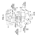
FIG. 3 , one embodiment of acooling system 60 is incorporated into a gas turbine system that utilizes CO2 removal and/or capture. Thecooling system 60 includes one ormore conduits 62 or other mechanisms for applying CO2 to various components of agas turbine 64. Thecooling system 60 also includes, in one embodiment, a gas turbine cooling CO2 controller 66 that includes processors, memory, transmission devices and/or displays suitable for controlling the operation of thecooling system 60 as well as receiving, processing, displaying and/or transmitting information regarding thecooling system 60. - In one embodiment, the
cooling system 60 is in operable communication with thegas turbine 64 and a portion of theAGR plant 42. TheAGR plant 42 includes one ormore flash tanks 68 that separate CO2 from a rich solvent.Gas conduits 69 are configured to route the separated CO2 from theflash tanks 68 to desired locations, such as the compression and/orstorage unit 46. In one embodiment, CO2 fluid from a H2S reabsorber 67 is routed to the gas turbine cooling CO2 controller 66. Thecooling system conduits 62 are in fluid communication withrespective gas conduits 69 to divert a portion of the separated CO2 into thecooling system 60. The flow of CO2 into the cooling system can be controlled by thecontroller 66. In one embodiment, thecooling system 60 includevalves 70 for controlling the flow of CO2 from thegas conduits 69, through thecooling system 60 and into thegas turbine 64. Thevalves 70 may be selectively operated via, for example, thecontroller 66. - The
cooling system 60, in one embodiment, is a closed loop system. For example, as shown inFIG. 3 , CO2 gas is flowed from thecooling system 60 into selected turbine stages, such as apower turbine stage 72, and is directed to selected moving and/or stationary components. The CO2 absorbs heat from the components, and the heated CO2 may be fed through a fuelline heat exchanger 74 and a diluentline heat exchanger 76 to heat fuel and diluent being fed into the turbine's combustion chamber 78. The CO2 continues on to at least oneadditional heat exchanger 80 to heat exhaust gases used in steam generation and trim cooling, before it is returned to one or more of thegas conduits 68 and/or a CO2 storage system. - Another embodiment of the
cooling system 60 is shown in reference toFIG. 4 . Thecooling system 60 in this embodiment is configured to communicate with an indirect cooling unit (ICU). The ICU defines the closed loop cooling of turbine components. CO2 fluid from the ICU is routed to heat exchangers (e.g, air-fluid heat exchanger, fluid-fuel heat exchanger, heat sinks, regenerative heat exchanger) and it is returned to the CO2 compression andsequestration unit 90. - In this embodiment, CO2 fluid from the ICU is fed to
heat exchangers 82 that are configured to transfer heat from the bleed CO2 to fluids such as the fuel, diluent, compressor discharge air and/or boiler feed water (BFW). Further heat is transferred back to the CO2 which is entering ICU through a regenerativeheat exchanger system 84. CO2 fluid can also be cooled through optional low temperature heat exchange systems 94 (e.g., trim coolers, other areas of steam heat exchangers and others) that further cool the CO2 to facilitate compression, liquefication and/or sequestration. Lastly, the cooled CO2 is diverted to the compression andsequestration unit 90. - In one embodiment, the
cooling system 60 is in fluid communication with a CO2 capture, recovery andsequestration system 86. The CO2 capture unit includes a number ofcapture modules 88. Exemplary capture modules includeflash tanks 68 which through which rich solvent is passed. Thecapture modules 88 can include high pressure (HP), medium pressure (MP) and/or low pressure (LP)modules 88 in fluid communication with a CO2 compression andsequestration unit 90. - In use, a portion of the CO2 from
capture modules 88 may be diverted through an optionalgas compression system 92 throughregenerative heat exchangers 84 to selected ICU of turbine components. -
FIG. 5 illustrates amethod 100 of cooling components of a turbine. Themethod 100 includes one or more stages 101-104. Although themethod 100 is described in conjunction with theIGCC power plant 30 and thecooling system 60, themethod 100 may be used with any system capable of cooling a turbine assembly as described herein. In one embodiment, themethod 100 includes the execution of all of stages 101-104 in the order described. However, certain stages may be omitted, stages may be added, or the order of the stages changed. - In the
first stage 101, fuel is flowed into a gasification system such as the gasification and scrubbingunit 32 and raw syngas is produced. The raw syngas is cleaned or sweetened by a suitable cleaning system such as theAGR plant 42 to remove acid gases from the raw syngas. - In the
second stage 102, CO2 gas is extracted from the raw syngas and/or from byproducts of cleaning the raw syngas. For example, CO2 gas is removed from a solvent used to clean the raw syngas by theflash tanks 68 or other CO2 extraction mechanisms. The CO2 gas is advanced to a CO2 capture and/or storage system, such as the compression and/orstorage unit 46. - In the
third stage 103, a portion of the CO2 gas is diverted to a cooling system such as thecooling system 60 that applies the CO2 gas portion to selected components of a turbine such as a gas turbine. Exemplary components include rotating blades or buckets and stationary components such as stator vanes. - In the
fourth stage 104, the CO2 gas portion, which has been heated by the turbine components, is recovered in thermal energy / regenerated and then returned to the CO2 capture and/or storage system. In one embodiment, the heated CO2 gas portion is cooled and thermal energy is transferred to fuel, diluents and/or other components of a power generation system prior to returning the CO2 gas portion to the CO2 capture and/or storage system. - In one embodiment, the CO2 gas portion is cooled by transferring thermal energy from the CO2 gas portion to an indirect cooling unit by a suitable heat exchange mechanism such as the
regenerative heat exchanger 84. - Although the systems and methods described herein are provided in conjunction with gas turbines, any other suitable type of turbine may be used. For example, the systems and methods described herein may be used with a steam turbine or turbine including both gas and steam generation.
- The systems and methods described herein may be utilized in conjunction with any of various turbine power generation systems, and are not limited to the specific power generation systems described herein. In addition, the systems and methods described herein may be utilized in place of or in addition to various other cooling systems. Examples of such cooling systems include closed loop systems using cooling media for hot gas path components such as steam, nitrogen and liquid (e.g., water) coolants.
- The devices, systems and methods described herein provide numerous advantages over prior art systems. The devices, systems and methods provide the technical effect of increasing efficiency and performance of the turbine. For example, based on analyses of exemplary systems, systems and methods such as those described herein can improve output and efficiency, for example by improving net output by 14.5% and efficiency by 0.52 points over the baseline scenario that is practiced in the prior art.
- While the invention has been described in detail in connection with only a limited number of embodiments, it should be readily understood that the invention is not limited to such disclosed embodiments. Rather, the invention can be modified to incorporate any number of variations, alterations, substitutions or equivalent arrangements not heretofore described, but which are commensurate with the spirit and scope of the invention. Additionally, while various embodiments of the invention have been described, it is to be understood that aspects of the invention may include only some of the described embodiments. Accordingly, the invention is not to be seen as limited by the foregoing description, but is only limited by the scope of the appended claims.
- For completeness, various aspects of the invention are now set out in the following numbered clauses:
- 1. A system for cooling components of a turbine, comprising:
- at least one input in fluid communication with a source of carbon dioxide gas, the carbon dioxide gas removed from synthesis gas produced by a gasification unit from a fuel; and
- at least one first conduit in fluid communication with the at least one input and configured to divert a portion of the carbon dioxide gas from the source of carbon dioxide gas to at least one component of the turbine, the turbine configured to combust the synthesis gas.
- 2. The system of clause 1, wherein the source of carbon dioxide gas is from an acid gas removal plant in fluid communication with the gasification unit, the acid gas removal plant configured to remove acid gases from the synthesis gas, the acid gases including carbon dioxide gas.
- 3. The system of
clause 2, wherein the acid gas removal plant is configured to apply a solvent to the synthesis gas, the solvent configured to extract the acid gases from the synthesis gas and retain the acid gases therein. - 4. The system of clause 3, wherein the source of carbon dioxide gas includes at least one of: a gasification unit, an oxyfuel cycle and a flash tank configured to remove the carbon dioxide gas from the solvent.
- 5. The system of clause 1, further comprising a second conduit configured to receive the portion of the carbon dioxide gas after the portion has been diverted to the at least one component, the second conduit in fluid communication with at least one carbon dioxide storage unit.
- 6. The system of clause 5, further comprising at least one heat exchanger in fluid communication with the second conduit and configured to transfer thermal energy from the portion of the carbon dioxide gas to at least one component of a power generation system including the turbine.
- 7. The system of clause 6, wherein the at least one component of the power generation system includes at least one of an indirect turbine cooling unit, a closed loop, a turbine fuel, a turbine diluent and a steam turbine.
- 8. A system for power generation, comprising:
- a gasification unit configured to produce raw synthesis gas from an input fuel;
- an acid gas removal plant in fluid communication with the gasification unit, the acid gas removal plant configured to remove acid gas from the raw synthesis gas and
- produce clean synthesis gas, the acid gas including carbon dioxide gas;
- a gas turbine configured to combust the clean synthesis gas; and
- a cooling unit in fluid communication with the acid gas removal plant and configured to divert at least a portion of the carbon dioxide gas to at least one component of a gas turbine.
- 9. The system of clause 8, further comprising a carbon dioxide storage unit in fluid communication with the acid gas removal plant.
- 10. The system of clause 9, further comprising a conduit in fluid communication with the at least one component and the storage unit, the conduit configured to advance the portion of the carbon dioxide gas to the storage unit after the portion has been diverted to the at least one component.
- 11. The system of
clause 10, further comprising at least one heat exchanger in fluid communication with the conduit and configured to transfer thermal energy from the portion of the carbon dioxide gas to at least one component of the system. - 12. The system of claim 8, further comprising an indirect cooling unit configured to cool the gas turbine, the indirect cooling unit in fluid communication with the portion of the carbon dioxide gas and configured to cool the portion of the carbon dioxide gas after the portion has been diverted to the at least one component.
- 13. A method of cooling components of a turbine, comprising:
- extracting carbon dioxide gas from a synthesis gas produced by a gasification process;
- advancing the carbon dioxide gas to a storage system; and
- diverting a portion of the carbon dioxide gas to the turbine to cool at least one component of the turbine.
- 14. The method of clause 13, wherein extracting the carbon dioxide gas includes applying a solvent to the synthesis gas, the solvent configured to extract acid gases from the synthesis gas and retain the acid gases therein.
- 15. The method of
clause 14, wherein extracting the carbon dioxide gas includes removing the carbon dioxide gas from the solvent. - 16. The method of clause 13, further comprising advancing the portion of the carbon dioxide gas from the turbine to the storage system after the portion has been diverted to the gas turbine.
- 17. The method of
clause 16, wherein advancing the portion of the carbon dioxide gas includes cooling the portion of the carbon dioxide. - 18. The method of clause 17, wherein cooling the portion of the carbon dioxide includes transferring thermal energy from the portion of the carbon dioxide gas to at least one component of a power generation system.
- 19. The method of
clause 18, wherein the at least one component of the power generation system at least one of an indirect turbine cooling unit, a closed loop, a turbine fuel, a turbine diluent and a steam turbine. - 20. The method of clause 13, wherein the turbine is a gas turbine.
Claims (15)
- A system for cooling components of a turbine (16, 64), comprising:at least one input in fluid communication with a source of carbon dioxide gas, the carbon dioxide gas removed from synthesis gas produced by a gasification unit (32) from a fuel; andat least one first conduit (62, 69) in fluid communication with the at least one input and configured to divert a portion of the carbon dioxide gas from the source of carbon dioxide gas to at least one component of the turbine (16), the turbine configured to combust the synthesis gas.
- The system of claim 1, wherein the source of carbon dioxide gas is from an acid gas removal (42) plant in fluid communication with the gasification unit (32), the acid gas removal (42) plant configured to remove acid gases from the synthesis gas, the acid gases including carbon dioxide gas.
- The system of claim 2, wherein the acid gas removal plant (42) is configured to apply a solvent to the synthesis gas, the solvent configured to extract the acid gases from the synthesis gas and retain the acid gases therein.
- The system of claim 3, wherein the source of carbon dioxide gas includes at least one of: a gasification unit (32), an oxyfuel cycle and a flash tank (68) configured to remove the carbon dioxide gas from the solvent.
- The system of any of the preceding claims, further comprising a second conduit (62, 69) configured to receive the portion of the carbon dioxide gas after the portion has been diverted to the at least one component, the second conduit (62, 69) in fluid communication with at least one carbon dioxide storage unit.
- The system of claim 5, further comprising at least one heat exchanger (74, 76) in fluid communication with the second conduit (62, 69) and configured to transfer thermal energy from the portion of the carbon dioxide gas to at least one component of a power generation system (30) including the turbine (16, 64).
- The system of claim 6, wherein the at least one component of the power generation system (30) includes at least one of an indirect turbine cooling unit, a closed loop, a turbine fuel, a turbine diluent and a steam turbine.
- A method of cooling components of a turbine, comprising:extracting carbon dioxide gas from a synthesis gas produced by a gasification process;advancing the carbon dioxide gas to a storage system; anddiverting a portion of the carbon dioxide gas to the turbine to cool at least one component of the turbine.
- The method of claim 8, wherein extracting the carbon dioxide gas includes applying a solvent to the synthesis gas, the solvent configured to extract acid gases from the synthesis gas and retain the acid gases therein.
- The method of claim 9, wherein extracting the carbon dioxide gas includes removing the carbon dioxide gas from the solvent.
- The method of claim 8, further comprising advancing the portion of the carbon dioxide gas from the turbine to the storage system after the portion has been diverted to the gas turbine.
- The method of claim 11, wherein advancing the portion of the carbon dioxide gas includes cooling the portion of the carbon dioxide.
- The method of claim 12, wherein cooling the portion of the carbon dioxide includes transferring thermal energy from the portion of the carbon dioxide gas to at least one component of a power generation system.
- The method of claim 13, wherein the at least one component of the power generation system at least one of an indirect turbine cooling unit, a closed loop, a turbine fuel, a turbine diluent and a steam turbine.
- The method of claim 8, wherein the turbine is a gas turbine.
Applications Claiming Priority (1)
| Application Number | Priority Date | Filing Date | Title |
|---|---|---|---|
| US12/729,745 US20110232298A1 (en) | 2010-03-23 | 2010-03-23 | System and method for cooling gas turbine components |
Publications (1)
| Publication Number | Publication Date |
|---|---|
| EP2369156A2 true EP2369156A2 (en) | 2011-09-28 |
Family
ID=43827868
Family Applications (1)
| Application Number | Title | Priority Date | Filing Date |
|---|---|---|---|
| EP11159016A Withdrawn EP2369156A2 (en) | 2010-03-23 | 2011-03-21 | System and method for cooling gas turbine components |
Country Status (4)
| Country | Link |
|---|---|
| US (1) | US20110232298A1 (en) |
| EP (1) | EP2369156A2 (en) |
| JP (1) | JP2011196378A (en) |
| CN (1) | CN102200057A (en) |
Families Citing this family (10)
| Publication number | Priority date | Publication date | Assignee | Title |
|---|---|---|---|---|
| CN102449124A (en) * | 2009-05-26 | 2012-05-09 | 巴斯夫欧洲公司 | Process for recovering carbon dioxide from a fluid stream, especially from synthesis gas |
| US8171718B2 (en) * | 2009-10-05 | 2012-05-08 | General Electric Company | Methods and systems involving carbon sequestration and engines |
| US9279340B2 (en) * | 2010-03-23 | 2016-03-08 | General Electric Company | System and method for cooling gas turbine components |
| CN103096999A (en) * | 2010-07-28 | 2013-05-08 | 萨加斯公司 | Jet engine with carbon capture |
| JP6278645B2 (en) * | 2012-09-24 | 2018-02-14 | キヤノン株式会社 | Photocurable composition and method for producing film using the same |
| US9611756B2 (en) | 2012-11-02 | 2017-04-04 | General Electric Company | System and method for protecting components in a gas turbine engine with exhaust gas recirculation |
| US9581081B2 (en) * | 2013-01-13 | 2017-02-28 | General Electric Company | System and method for protecting components in a gas turbine engine with exhaust gas recirculation |
| US10344673B2 (en) * | 2016-06-27 | 2019-07-09 | General Electric Company | System and method of cooling a turbine engine |
| CN111422872B (en) | 2019-01-10 | 2022-01-25 | 国家能源投资集团有限责任公司 | System and method for capturing carbon dioxide from a carbon dioxide generating asset group |
| CN113074025B (en) * | 2021-04-30 | 2025-05-16 | 中国科学院工程热物理研究所 | Supercritical CO2 turbine inter-shaft cooling test system |
Family Cites Families (40)
| Publication number | Priority date | Publication date | Assignee | Title |
|---|---|---|---|---|
| US3164955A (en) * | 1958-10-20 | 1965-01-12 | George H Garraway | Turbo compressor drive for jet power plant |
| US4190398A (en) * | 1977-06-03 | 1980-02-26 | General Electric Company | Gas turbine engine and means for cooling same |
| DE3261410D1 (en) * | 1981-04-03 | 1985-01-17 | Bbc Brown Boveri & Cie | Combined steam and gas turbine power plant |
| US5095693A (en) * | 1989-08-04 | 1992-03-17 | United Technologies Corporation | High-efficiency gas turbine engine |
| USRE36497E (en) * | 1993-11-04 | 2000-01-18 | General Electric Co. | Combined cycle with steam cooled gas turbine |
| US5577377A (en) * | 1993-11-04 | 1996-11-26 | General Electric Co. | Combined cycle with steam cooled gas turbine |
| US5428950A (en) * | 1993-11-04 | 1995-07-04 | General Electric Co. | Steam cycle for combined cycle with steam cooled gas turbine |
| DE4409567A1 (en) * | 1994-03-21 | 1995-09-28 | Abb Management Ag | Process for cooling thermally loaded components of a gas turbine group |
| KR100389990B1 (en) * | 1995-04-06 | 2003-11-17 | 가부시끼가이샤 히다치 세이사꾸쇼 | Gas turbine |
| US5742022A (en) * | 1995-04-19 | 1998-04-21 | Dct Avanced Engineering, Inc. | Industrial workcell system and method |
| US5724805A (en) * | 1995-08-21 | 1998-03-10 | University Of Massachusetts-Lowell | Power plant with carbon dioxide capture and zero pollutant emissions |
| US5611197A (en) * | 1995-10-23 | 1997-03-18 | General Electric Company | Closed-circuit air cooled turbine |
| US5865598C1 (en) * | 1997-07-02 | 2001-01-02 | Siemens Westinghouse Power | Hot spot detection system for vanes or blades of a combustion turbine |
| JPH1193694A (en) * | 1997-09-18 | 1999-04-06 | Toshiba Corp | Gas turbine plant |
| US6065282A (en) * | 1997-10-29 | 2000-05-23 | Mitsubishi Heavy Industries, Ltd. | System for cooling blades in a gas turbine |
| US5960249A (en) * | 1998-03-06 | 1999-09-28 | General Electric Company | Method of forming high-temperature components and components formed thereby |
| US6197424B1 (en) * | 1998-03-27 | 2001-03-06 | Siemens Westinghouse Power Corporation | Use of high temperature insulation for ceramic matrix composites in gas turbines |
| JPH11311103A (en) * | 1998-04-27 | 1999-11-09 | Toshiba Corp | High-temperature components, high-temperature components for gas turbines, and methods for producing them |
| JP3800384B2 (en) * | 1998-11-20 | 2006-07-26 | 株式会社日立製作所 | Combined power generation equipment |
| JP3422731B2 (en) * | 1999-07-23 | 2003-06-30 | 理化学研究所 | ELID centerless grinding machine |
| US6295803B1 (en) * | 1999-10-28 | 2001-10-02 | Siemens Westinghouse Power Corporation | Gas turbine cooling system |
| US6506013B1 (en) * | 2000-04-28 | 2003-01-14 | General Electric Company | Film cooling for a closed loop cooled airfoil |
| US6487863B1 (en) * | 2001-03-30 | 2002-12-03 | Siemens Westinghouse Power Corporation | Method and apparatus for cooling high temperature components in a gas turbine |
| US6684653B2 (en) * | 2001-11-21 | 2004-02-03 | Nicholas H. Des Champs | Air-conditioner and air-to-air heat exchange for closed loop cooling |
| US6672075B1 (en) * | 2002-07-18 | 2004-01-06 | University Of Maryland | Liquid cooling system for gas turbines |
| GB2401403B (en) * | 2003-05-08 | 2006-05-31 | Rolls Royce Plc | Carbon dioxide recirculation |
| US6938439B2 (en) * | 2003-05-22 | 2005-09-06 | Cool Clean Technologies, Inc. | System for use of land fills and recyclable materials |
| US7231769B2 (en) * | 2004-01-29 | 2007-06-19 | United Technologies Corporation | Gas turbine cooling system |
| US7178339B2 (en) * | 2004-04-07 | 2007-02-20 | Lockheed Martin Corporation | Closed-loop cooling system for a hydrogen/oxygen based combustor |
| US6988367B2 (en) * | 2004-04-20 | 2006-01-24 | Williams International Co. L.L.C. | Gas turbine engine cooling system and method |
| US7637109B2 (en) * | 2004-08-02 | 2009-12-29 | American Air Liquide, Inc. | Power generation system including a gas generator combined with a liquified natural gas supply |
| US7581401B2 (en) * | 2005-09-15 | 2009-09-01 | General Electric Company | Methods and apparatus for cooling gas turbine engine components |
| US7359198B2 (en) * | 2005-09-29 | 2008-04-15 | Avago Technologies General Ip (Singapore) Pte. Ltd. | System and method for inducing turbulence in fluid for dissipating thermal energy of electronic circuitry |
| US7726114B2 (en) * | 2005-12-07 | 2010-06-01 | General Electric Company | Integrated combustor-heat exchanger and systems for power generation using the same |
| GB2433581B (en) * | 2005-12-22 | 2008-02-27 | Siemens Magnet Technology Ltd | Closed-loop precooling of cryogenically cooled equipment |
| US7892324B2 (en) * | 2007-10-10 | 2011-02-22 | General Electric Company | Systems and methods for carbon dioxide capture |
| US20090149930A1 (en) * | 2007-12-07 | 2009-06-11 | Thermage, Inc. | Apparatus and methods for cooling a treatment apparatus configured to non-invasively deliver electromagnetic energy to a patient's tissue |
| US8438874B2 (en) * | 2008-01-23 | 2013-05-14 | Hitachi, Ltd. | Natural gas liquefaction plant and motive power supply equipment for same |
| US20100018216A1 (en) * | 2008-03-17 | 2010-01-28 | Fassbender Alexander G | Carbon capture compliant polygeneration |
| US8171718B2 (en) * | 2009-10-05 | 2012-05-08 | General Electric Company | Methods and systems involving carbon sequestration and engines |
-
2010
- 2010-03-23 US US12/729,745 patent/US20110232298A1/en not_active Abandoned
-
2011
- 2011-03-21 EP EP11159016A patent/EP2369156A2/en not_active Withdrawn
- 2011-03-22 JP JP2011062478A patent/JP2011196378A/en not_active Withdrawn
- 2011-03-23 CN CN201110080230XA patent/CN102200057A/en active Pending
Non-Patent Citations (1)
| Title |
|---|
| None |
Also Published As
| Publication number | Publication date |
|---|---|
| JP2011196378A (en) | 2011-10-06 |
| US20110232298A1 (en) | 2011-09-29 |
| CN102200057A (en) | 2011-09-28 |
Similar Documents
| Publication | Publication Date | Title |
|---|---|---|
| EP2369156A2 (en) | System and method for cooling gas turbine components | |
| EP2689109B1 (en) | Systems and methods for carbon dioxide capture in low emission combined turbine systems | |
| US9027321B2 (en) | Low emission power generation and hydrocarbon recovery systems and methods | |
| TWI564475B (en) | Low emission triple-cycle power generation systems and methods | |
| JP5868113B2 (en) | Combined cycle power plant with carbon dioxide collection system | |
| US20140007590A1 (en) | Systems and Methods For Carbon Dioxide Capture In Low Emission Turbine Systems | |
| BR112013008661B1 (en) | energy production system and method | |
| EP2588732A1 (en) | Low emission triple-cycle power generation systems and methods | |
| CN102084105A (en) | Thermal power generation equipment with CO2 storage capacity | |
| EP1102926B1 (en) | Fuel gas turbo-expander for oxygen blown gasifiers and related method | |
| US9279340B2 (en) | System and method for cooling gas turbine components | |
| RU2837807C2 (en) | Electric power generation system, which includes gas turbine with heat recovery steam generator and carbon dioxide trapping, and method | |
| KR20250141143A (en) | Combustion system with fuel cell and carbon capture system | |
| KR20250137586A (en) | Combustion system with fuel cell and carbon capture system | |
| TW201303142A (en) | Systems and methods for carbon dioxide capture in low emission turbine systems |
Legal Events
| Date | Code | Title | Description |
|---|---|---|---|
| PUAI | Public reference made under article 153(3) epc to a published international application that has entered the european phase |
Free format text: ORIGINAL CODE: 0009012 |
|
| AK | Designated contracting states |
Kind code of ref document: A2 Designated state(s): AL AT BE BG CH CY CZ DE DK EE ES FI FR GB GR HR HU IE IS IT LI LT LU LV MC MK MT NL NO PL PT RO RS SE SI SK SM TR |
|
| AX | Request for extension of the european patent |
Extension state: BA ME |
|
| STAA | Information on the status of an ep patent application or granted ep patent |
Free format text: STATUS: THE APPLICATION IS DEEMED TO BE WITHDRAWN |
|
| 18D | Application deemed to be withdrawn |
Effective date: 20151001 |